Abstract
This work evaluates the experimental test results regarding the operational performance of a free-float capable tension leg platform with a 10 MW wind turbine. It covers the platform dynamics in the selected installation area: Ribadeo, Spain. The model and the facility are initially presented, along with the experimental setup and the load cases. The testing campaign includes a software-in-the-loop method to emulate the rotor thrust and the aerodynamic and gyroscopic moments in pitch and yaw. The result sets are structured to start from basic information from system identification cases and continue with responses against regular and irregular waves accompanied by steady and stochastic wind scenarios. The performance in operational and extreme conditions is assessed as well as fault scenarios. The experiments demonstrate auspicious motion dynamics and mooring line behavior when examined against class society rules.
1. Introduction
Environmental and political status expand the shift to renewable resources as energy dependence is ever-increasing [1]. Among renewable resources, wind energy is one of the fastest-growing sectors and covers 35% of renewables [2]. While the total wind capacity is increasing [3], offshore wind has some advantages over onshore wind. The high offshore wind potential and the long distance from the coast allow higher energy extraction with a reduced impact on residential areas [4]. Thus, offshore wind is advantageous with the possibility of implementing larger turbines [5].
In this regard, the move offshore has been conspicuous, even more so in deeper water and floating turbines [6]. Several projects evaluated alternative platforms to support multi-megawatt wind turbines [7,8,9,10]. ARCWIND (Adaptation and Implementation of Floating Wind Energy Conversion Technology for the Atlantic Region) is one project seeking to develop capable 10 MW floating wind turbines (FWTs). In ARCWIND, the wind energy potential in the Atlantic area is assessed [11,12,13], the best locations for wind farms are chosen [14], the feasibility of different FWT technologies is studied [15,16,17], and the logistics and economics of deploying these concepts in a full-scale farm environment are considered [18]. Within the project, Three FWT models are designed: a spar [19], a barge semisubmersible [20], and a tension leg platform (TLP) [21].
Regarding performance, TLPs have a minimal dynamic response in the restricted modes (i.e., heave, roll, pitch). Their stability relies on taut mooring lines, and the platform responds in a way similar to a rigid structure in terms of motion amplitudes and resonance frequencies. The minimal pitching response is an advantage for power production as it affects the aerodynamic performance of wind turbines [22,23,24]. Thus, compared to other floaters, the TLP’s generated power is less affected by motion amplitudes, for instance, larger pithing angles that can change the turbine aerodynamics.
Over the years, alternative TLP designs with various hull geometries, such as one-column [25,26,27] and four-column [28,29] designs, have been considered as possible hull forms. The single-column hull form originates from the SeaStar platform [26,30]. It was suggested as a means of reducing the hull weight compared to the conventional four-column form, which ConocoPhillips first installed in the 1980s. However, a smaller waterplane area signifies that, without ballasting, the hull form is limited in providing stability during installation cases and will likely require specialized vessels, such as installation barges, to transport the system to the installation site [31]. Since installation in larger numbers (i.e., wind farms) becomes economically unfavorable, this hull form has not been used even in demo projects to date. Hence, developing alternatives to keep the advantages of the TLP dynamics while addressing the disadvantages becomes necessary. The CENTEC-TLP was developed with these constraints in mind.
Unlike SeaStar-type TLP designs [27,32], the CENTEC-TLP has sufficient stability in free-floating conditions, as it follows the principles of a barge for transportation purposes. It makes use of a large waterplane area, thus benefitting from a low transport draft, making it accessible to low-depth ports and shipyards. The platform’s design development followed a series of stages as described by renewable industries in terms of Technology Readiness Levels (TRLs) [33,34]. The proof of concept (i.e., TRLs 1–3) involved the design procedure explained in [21,35,36], development of the hull form [15] and evaluation of the numerical performance [37,38,39]. The validation stage (i.e., TRLs 4–6) included testing a scaled model [40], as experimental testing allows the investigation of the system dynamics in a realistic environment [41]. This phase aimed to confirm the system dynamics, verify the mooring system, and collect sufficient data for future optimization of the numerical model if needed.
In this scope, the CENTEC-TLP was tested at the Universidad Politécnica de Madrid (UPM) towing tank. Initial results regarding the transportation dynamics and wave resistance are published in [42]. The results show a maximum heeling of 2 degrees in 3 m significant wave height. Given that a significant wave height above 1.5 meters is not usually considered favorable for installation, it can be stated that the design shows favorable motion dynamics for transport. The studies continued with the evaluation of the system dynamics and the mooring lines in operational, extreme, and fault conditions. The tests were conducted with the same prototype used in the transportation tests. They included adding a software-in-the-loop (SiL) system for wind load generation [43]. The aerodynamic system improvement comprises the emulation of the rotor thrust and the aerodynamic and gyroscopic pitch and yaw moments explained in [44], unlike the initial systems representing the thrust only [45]. The inclusion of the SiL avoids the Froude–Reynolds scaling conflict [46] and allows the testing of wind turbine pitch control strategies [47].
This work expands the initial set of data published in the experimental results from the CENTEC-TLP testing campaign [40]. It focuses on the installed platform and evaluates the operational performance. The paper starts by describing the design, the prototype, and the towing tank. Identification cases of free decays are then presented. They are followed by the response amplitude operators (RAOs) in regular waves and steady wind. Then, irregular waves and turbulent wind cases are evaluated, representing operational, extreme, and faulty conditions. The mooring line breaking and slacking are examined according to class society rules. All results are presented at full scale.
2. Model and Prototype Description
2.1. The Design
2.1.1. The Wind Turbine and Tower
The CENTEC-TLP (Figure 1—left) was designed for the DTU 10 MW turbine and tower [48]. The turbine is upscaled from the 5 MW NREL reference turbine [49], with a shorter tower and larger hub diameter compared to direct upscaling. Its specifications and mass properties are listed in Table 1. In addition, a clearance (i.e., the height of the platform-to-tower connection) of 10 m is set to prevent the waves from affecting the blades and the tower. This value matches the DeepCwind design [50] at 10 m above the mean sea level (MSL), regardless of the environmental conditions.
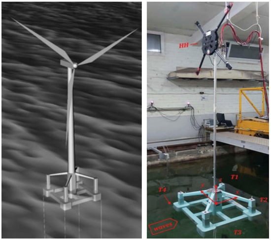
Figure 1.
The CENTEC-TLP design (left) and prototype (right).

Table 1.
Specifications of the DTU 10MW WT.
The tower’s mass and inertial data are in Table 2, and those for the nacelle and the rotor are in Table 3. The tower and the rotor nacelle assembly (RNA) combination details are provided in Table 4. Note that the 10-m base height locates the structure’s centre of gravity (CoG) at 95.9 m above MSL. The eccentricity in the longitudinal direction results from the offset of the centre of mass of the turbine.

Table 2.
Mass details of the tower model and the moments of inertia about its center of gravity.

Table 3.
Mass details of the nacelle and rotor assembly.

Table 4.
Mass details of the tower, rotor, and the nacelle combination.
2.1.2. The CENTEC-TLP Platform
The CENTEC-TLP (Figure 1) is designed in the ARCWIND project to support the DTU 10 MW wind turbine. The physical properties and the numerical performance can be found in [15,21,37,51]. It is symmetrically designed with a square-shaped ring pontoon and four rectangular stability columns. A central column supports the tower at the centre of a cross-shaped inner pontoon. The design involves four diagonal support braces for better structural integrity. The sides length is 49 m and the draft is 20 m. The primary material is steel with no ballasting, which keeps the mass low as possible (i.e., 2200 tons) while adding the free-float capabilities. The system floats on the pontoons during the transportation phase as a barge. Compared to cylindrical designs, rectangular pontoons are easier and cheaper to fabricate [52]. They also maintain the waterplane area when the platform heaves, preserving its stability.
2.2. The Prototype
2.2.1. Towing Tank and Data Acquisition
The CEHINAV research group carried out the experimental tests. They manage the Universidad Politécnica de Madrid (UPM) towing tank, whose length and breadth are 100 m and 3.8 m, respectively. The facility is equipped with a single paddle wave generator capable of generating up to 0.3 m waves. It also includes a passive wave absorption area. During the tests, the depth was set to 127.2 m (2.12 m model scale). This value was set to avoid exceeding the wave generator limits. The CENTEC-TLP design is adapted to the Ribadeo (Spain) site, where the water depth is 132 m [53,54].
The data acquisition is made with a sampling frequency of 100 Hz. This value is sufficient since the typical frequencies of the investigated phenomena are in the order of 1.2 Hz. The collected data include the mooring line tensions, the wave elevation, and the recorded motions. An optical tracking system is used for recording the six DOF motions. The system consists of four infrared cameras fixed on the tank’s walls, tracking the displacements and rotations for at least five markers. The in-house system “HarbourDuino Mini” manages the storage of the tracked motions and the synchronization with other measurements.
2.2.2. Prototype Properties
The experiment involves a 1:60 Froude-scaled prototype. The scaling factor targets the installation depth and fulfils the 20% Chakrabarti’s limit [55] of the tank width for model testing. In addition, the scale satisfies the ITTC recommendations [56,57] to fit the prototype in the basin dimensions, avoid interactions with the reflected waves from the side walls, uphold the wave maker capacity, and correctly scale the mooring lines. A silicone woven fibreglass and epoxy resin composite material are used to build the prototype. The material selection considers the geometrical complexity of the hull to guarantee a low mass, leaving a proper margin for calibrations. Table 5 summarizes the design and prototype properties.

Table 5.
Design and prototype properties (full scale).
For a TLP, setting the mooring line pretensions correctly is a priority to replicate its dynamics. In this regard, the buoyancy excess plays a major role. Accordingly, the mass and the displaced volume are set as the main targets for the scaling. The total mass (including the tower and RNA) scaling presents a minimal deviation of 0.24%. The draft, and therefore the displaced volume, matches the design value. Regarding the inertia, the lower columns were reinforced for better structural integrity, as shown in Figure 2. The reinforcements lead to a higher mass in these zones. The current calibration is the chosen compromise to match the roll, pitch, and yaw inertias.
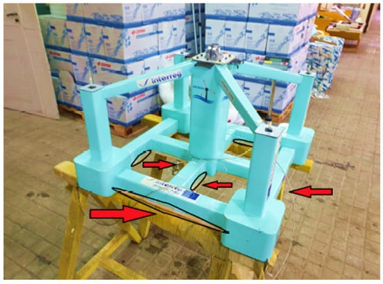
Figure 2.
Lower columns’ reinforcements.
2.2.3. Modeling of the Mooring Lines
In the design case, the CENTEC-TLP is moored with 12 tendons of 14 cm diameter. The 6-strand wire rope material is used with three lines attached to each corner. In the experiments, four tendons were used to represent three designed mooring lines each. Accordingly, the mooring stiffness and pretensions were conserved on each corner. This truncation is set according to the ITTC recommendations [58], where the total mass, the total stiffness, and restoring moments of the floating structure are conserved. Each mooring line is modelled with a spring connected to the platform via a stainless-steel wire and a screw (Figure 3). The mooring properties on each side are presented in Table 6 and Table 7. The slight difference in the mooring pretensions results from the inclusion of the lines’ weight. The load cell hanging in the lines is heavier than their actual mass scale and causes a difference in the pretensions. The tension adjustment is made through the connecting bolts while maintaining the 20 m draft. In the nomenclature, the lines T3 and T4 are located upwind, while T1 and T2 are downwind (Figure 1—right).

Figure 3.
The mooring line used in the experiment.

Table 6.
Design and prototype mooring pretensions.

Table 7.
Design and prototype mooring stiffness.
2.2.4. Emulation of Aerodynamic Loads
Froude-scaled rotors under an air flow produce out-of-scale aerodynamic loads due to a lower Reynolds number compared to the full-scale rotor. In the experiments, an actuator emulates the aerodynamic loads from the wind turbine at the hub height. The technique is referred to as the software-in-the-loop method (SiL), where the aerodynamic loads are Froude-scaled and included via actuators. SiL is a hybrid approach that combines physical testing and numerical simulation [59,60]. The communication between the actuators and the simulation is done in real time through a set of sensors and a motion-tracking system [46,47]. ITTC categorizes this technique as a functional practice to investigate the dynamic response of FWTs in operational and extreme conditions [33].
The National Renewable Energy Center (CENER) provided the SiL application in the experiment. Unlike initial SiL systems limited to the thrust force [45], an improved version of SiL is adopted, emulating, in addition to the rotor thrust, the aerodynamic and gyroscopic yaw and pitch moments. The emulator is composed of four drone propellers equally distributed around a drone chassis located at the hub height, as shown in Figure 1 (right). The calibration and the performance of the SiL system on the CENTEC-TLP are detailed in [43]. This configuration produces an approximate force range of 0-24N.
A schematic of the system is illustrated in Figure 4. Each propeller is powered by a brushless motor and fed with an AC/DC power supply. The thrust forces are controlled by the motor rotational speed set by the electronic speed controller (ESC), which is regulated by a pulse width modulation (PWM) signal generated by the LabVIEW control software, using servo libraries for Arduino. FAST [61] is used to simulate the turbine aerodynamics in real-time taking into account the measured motions. FAST’s output contains all loads from the rotor, including the applied aerodynamic, gravitational, and inertial loads. The loads are fed to the propellers via a calibration curve relating the requested force to the required PWM signal.
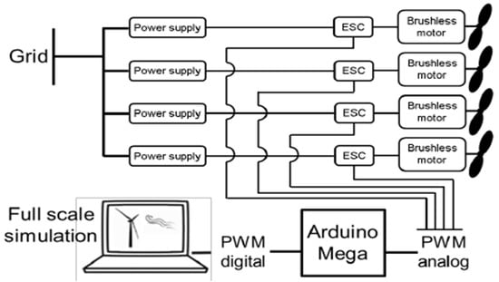
Figure 4.
Schematic of the software in the loop technique.
Concerning the tower, the first bending mode is set as a goal for the scaling. The first set of tests is conducted when the tower is cantilevered on a stable base (Figure 5), with the mass on its top representing the RNA. Bending tests are conducted, and the fore-aft and side-side periods are 4.25 s, roughly equal to the actual design period of 4 s. Tower identification test when fixed on the platform, is presented in Section 4.1.
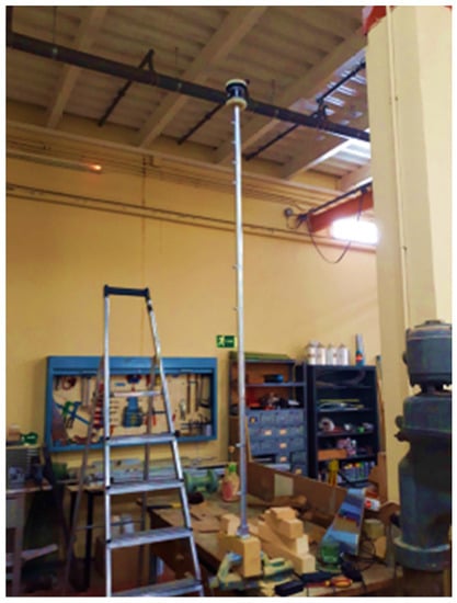
Figure 5.
Tower bending test.
3. Operational Criteria and Experimental Matrix
3.1. Criteria
The experimental campaign focuses on operational, extreme, and fault conditions. The wind and wave conditions represent the installation environment in Ribadeo, Spain, selected within the ARCWIND project [11,62]. The results are examined and compared to the criteria discussed by DNV [63,64,65] and API [66,67] and summarized in Table 8.

Table 8.
Operational and design criteria for the CENTEC-TLP.
Ideally, tension leg platforms should limit the surge motion to stay below a five-degree mooring angle limit at the anchors [68]. This condition is given for steel tethers with limited flexibility. However, CENTEC-TLP utilizes flexible wire rope lines. Still, this recommendation was considered in the design process. Hence, the 5-degree anchor angle safety limit is equivalent to a 9 m surge displacement.
On the other hand, breaking the mooring lines is an ultimate limit state for the TLP. Hence, this value needs to be observed in all conditions. The line-breaking tension (Fbreak) is 12,000 kN for each of the 12 tendons [15]. The experimental prototype has four lines, each mimicking the behavior of three tendons, as described in Section 2.2.3. Thus, the breaking tension in this assessment is set to 36,000 kN.
Finally, the line tension should stay above 20% of the pretension (i.e., 2182 kN) to avoid a case considered slack [64]. Once the mooring line tensions drop below a certain value, they enforce high dynamic loads when they come back into tension, causing a series of failures.
3.2. Experimental Matrix
Several tests were conducted at UPM to evaluate the operational and survivability criteria. The experimental test matrix is summarized in Table 9. The evaluated cases are classified into two categories, including controlled and stochastic environments. Controlled scenarios involve identification cases of free decays, regular waves, and steady wind conditions. The stochastic conditions serve to evaluate the operational performance in irregular waves and turbulent wind environments, in addition to the survivability in extreme and fault scenarios. The system is designed for Ribadeo, in the north of Spain, with the scatter diagram shown in Table 10. Accordingly, the tested conditions are selected from the scatter diagram using the waves with the highest probability in the installation site.

Table 9.
Experimental test matrix.

Table 10.
Scatter diagram of Ribadeo showing the probabilities of wave height and period combinations [12,62].
3.2.1. Decay Tests
Identification tests as free decays are made to evaluate the system’s natural periods. This testing is conducted by displacing the model from its static equilibrium position in a particular DoF, and then releasing it to oscillate in free motion. The system is observed to swing around the equilibrium position with a smaller amplitude after every oscillation because the damping forces remove mechanical energy from the system, whereas there is no excitation force. Theoretically, the angular frequency of this oscillatory motion may differ from the natural frequency; however, the values will be close to identical when damping forces are relatively weak. Accordingly, the natural period is obtained by averaging the results of the Fourier analysis applied to the motion signals from different runs. Another set of surge and pitch decays, including steady wind loads, is made to assess the aerodynamic damping effects on the system. The wind scenarios represent the below-rated (8.65 m/s), rated (11.4 m/s), and the above-rated (20.17 m/s) wind speeds.
3.2.2. Steady Wind and Regular Waves
The second set of tests includes steady wind conditions are summarized in Table 11. The steady wind loads were emulated via CENER’s SiL system. The offsets in the motions and mooring line tensions are assessed according to operational criteria (Table 8), highlighting the contribution of wind loads to the system dynamics.

Table 11.
Steady wind conditions.
In the third set of tests, the system was subjected to only regular head waves and regular head waves combined with steady wind loads. The regular waves combined with steady wind conditions are summarized in Table 12. The first wave was selected to identify the problems that may occur close to the resonance conditions. The limit and forced-limit tests represent the operational scenario bounds in the installation site, and the 50-years test refers to the extreme sea state. The analysis was then carried out according to the ITTC recommendations [69]: the response amplitude operators (RAOs) are estimated using the Fourier analysis of the motions, mooring tensions, and wave signals. Only the steady part of the signal, excluding the time when the refracted waves reach the model, was analysed, and a minimum of 10–20 cycles were taken to obtain the RAOs. The example in Figure 6 shows the TLP unique behavior in heave when excited by regular waves. Due to the taut tendons, both positive and negative surge induce a downward heave motion (i.e., a set down). That is, the heave motion has spikes at twice the surge motion frequency. In this case, only the spikes occurring at the wave frequency are considered for the RAOs.

Table 12.
Regular wave and steady wind conditions.
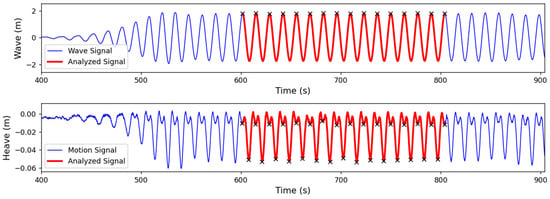
Figure 6.
Example of heave and wave signals in regular wave conditions.
3.2.3. Stochastic Environments
The operational performance in stochastic wind and wave environments and the survivability in extreme conditions are also evaluated. Wind speed scenarios covering all the turbine states were selected for this analysis (Table 13). The wind and waves are aligned and have a 180-degree heading (i.e., head waves). The JONSWAP spectrum with a peak parameter of 1 is used for the irregular waves in operational conditions and 1.45 in extreme scenarios. Statistical analysis of the motions and mooring lines was made to assess the system dynamics and examine them against class society rules.

Table 13.
Stochastic and extreme wind and wave conditions.
The last test sets assess the dynamics in fault conditions. DNV recommends testing emergency shutdown scenarios since mooring slack does not necessarily occur in extreme events but may occur in emergency stop cases [64]. In addition, controller error (i.e., one blade pitch angle set incorrectly) may cause platform yawing in operational conditions [70]. Accordingly, emergency shutdown tests in four conditions (Table 14) in the rated and above-rated steady wind conditions (i.e., 11.4 and 20.17 m/s) are examined.

Table 14.
Wind and wave conditions for emergency shutdown tests.
4. Results in Controlled Environment Settings
4.1. Decay Tests
The system’s natural periods are identified with decay tests. The measured values are recapped in Table 15. The surge and sway periods are within the design target surpassing 25 s (Table 8) and read 27.4 s and 27.8 s, respectively. The roll and pitch also respect the design criteria and reside below the 5 s limit. The deviations compared to the design are less than 5% for most measured periods.

Table 15.
Natural Period of the system.
Due to the high stiffness of the mooring lines, heave decay tests were difficult to carry out. Displacing the model in heave resulted in tendon tension loss or rapid decays with limited oscillations. In both cases, the signal has noise due to the mooring responses. While the white noise wave spectrum test can provide an estimate of the heave period, the physical limitation of the wave maker did not allow for testing waves below a 5 s period. In this case, the analysis from the white noise test did not provide a clean signal to identify the heave natural period. Since the mass and the line stiffness were correctly scaled and other modes, such as surge, had deviations under 5 percent, it was considered close to the design value (i.e., approximately 2 s). Compared to pitching and rolling periods, this value is farther away from the first-order wave period. Hence, heave is unlikely to be excited without the second-order loads.
Table 16 shows the results of the surge and pitch decays in steady wind. The aerodynamic damping effect is seen by the slight change in the periods. The SiL system used for the wind load generation is connected to the wind turbine simulator “FAST”. All phenomena captured by FAST are reproduced by the SiL actuators, including the aerodynamic damping.

Table 16.
Natural periods of the system with steady wind loads.
Regarding the tower, the first-mode period was measured with bending tests. The period in the cantilevered configuration (i.e., 4.25 s in Section 2.1) increased to 4.7 s when the tower was clamped to the floater. This variation is also seen in other testing campaigns [10,71,72]. The increase in the tower’s first-mode periods is related to the floater flexibility and the rigidity of the clamping between the tower and the floater. The value of 4.7 s is accepted as it lays outside the first-order wave excitation range of 5 to 25 s [65].
4.2. Steady Wind Responses
Steady wind tests (Table 11) are made to check the system response against the wind in operational and extreme conditions. The primary influence of wind is on surge and pitch since only 180-heading wind is used. Table 17 and Table 18 show the mean offsets of motions and line tensions, respectively. The results fulfil the operational and survivability criteria (Table 8) and leave a sufficient margin for wave loads. The maximum surge noted at the rated wind scenario is 3.65 m; the value is below the maximum allowed surge displacement (9 m). The rotational motions are also negligible, as expected from a TLP. The tendon tensions are situated in the allowed range (i.e., above 2182 kN and below 36,000 kN) and avoid the breaking and slacking phenomenon.

Table 17.
Motions in steady wind conditions.

Table 18.
Line tensions in steady wind conditions.
4.3. Regular Wave and Steady Wind Responses
The tested steady wind and regular waves are summarized in Table 12. The turbine is parked when only subjected to waves. It operates when the wind is introduced. Figure 7 and Figure 8 illustrate the motions and the line tensions RAOs, respectively. As a TLP, the system responds minimally to waves in most degrees of freedom. The amplitudes stay below 0.02 deg/m in roll, under 0.045 deg/m for pitch, and less than 0.05 deg/m in yaw. In surge, a longer wave period induces a higher response. While heaving is small in term of motion dynamics, it mainly affects the mooring response of the TLP.
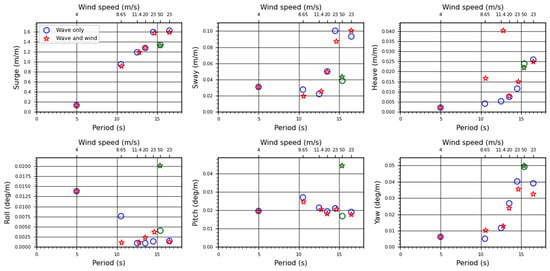
Figure 7.
Response amplitude operators of the motions in regular wave conditions. The green markers (at T = 15.38 s) represent the 50-year extreme condition.
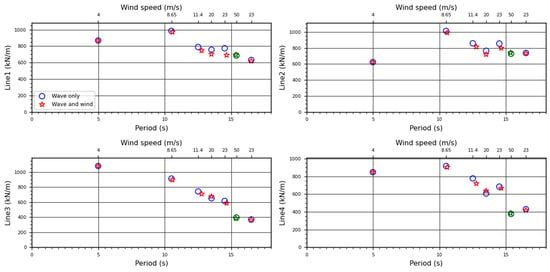
Figure 8.
Response amplitude operators of the moorings in regular wave conditions. The green markers (at T = 15.38 s) represent the 50-year extreme condition.
As for the moorings, the tendons T3 and T4 are attached to the upwind columns, while T1 and T2 are the downwind ones. T3 and T4 behave identically in most of the tested waves. The case is the same for T1 and T2. However, the resonance test case (i.e., 5 s wave period) shows different behaviour. T1 and T3 have a higher response compared to T2 and T4. The roll motion seen in Figure 7 (i.e., 0.014 deg/m) may be causing this difference. In addition, the mooring RAOs are roughly identical in both regular waves and the combined regular waves and steady wind conditions. While the heave RAOs show some discrepancy due to wind (i.e., at 8.65 and 11.4 m/s), the discrepancy almost vanishes in the mooring response.
The 50-year extreme condition result is highlighted in green (i.e., at 15.38 s). The response is nearly linear with respect to the operational conditions. The system responds minimally to waves and wind, as reflected in the mooring lines. In this case, the rotational motions are more affected, recording the highest peaks. The tests with wave and wind are roughly identical to those with waves only in most scenarios. These results show that the RAOs depend mainly on the wave frequency and direction.
5. Results in Stochastic Environment
5.1. Stochastic and Extreme Wind and Wave Conditions
The operational and extreme conditions are recapped in Table 13. In all scenarios, the wind and waves are unidirectional. The JONSWAP spectrum was used for the waves. The peak parameter is 1 and 1.45 for the operational and 50-years cases, respectively. The wind loads are emulated using CENER’s SiL system. The match between the wave height and the wind speed is done using the scatter diagram of the Ribadeo installation area.
Figure 9 and Figure 10 show the maximum, minimum, and standard deviation of the motions and mooring line tensions. The maximum surge motion is 6.3 m, occurring in the above-rated condition. The maxima are close for the rated, above-rated, and limit conditions. They are lower than 9 m, keeping the anchor angle below the 5-degree safety limit. Compared to the above-rated wind case, the rated wind case introduces a higher turbine trust. At the same time, wave forces increase, given the wind speed and wave height correlation. These results show that the change in wind and wave forces are similar.
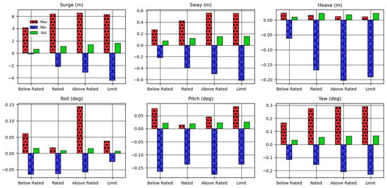
Figure 9.
Maximum, minimum, and standard deviation of the motions in operational conditions.
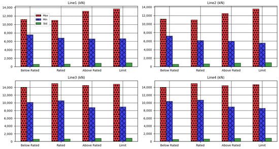
Figure 10.
Maximum, minimum, and standard deviation of the mooring tensions in operational conditions.
The maxima for heave and sway motions may be considered small. However, the minimum for heave can reach 20 centimeters. While the absolute values may look negligible, they are not direct indicators of the TLP’s performance. They will reflect as changes in mooring line tensions. This relation is further discussed when presenting the mooring line tensions.
The rolling and pitching motions stay below approximately 0.05 and 0.16 degrees, respectively. The existence of rolling motion signifies that the model is not entirely symmetrical regarding its setup, which can be confirmed by checking the initial mooring line tensions. In all cases, the motions are limited, as expected from a tension leg platform.
The primary advantage of these smaller motions is that the reflection on the aerodynamics is limited as the platform never pitches to a point where it can alter the aerodynamic response of the blades. Higher platform pitch eventually affects the blade geometry that encounters the wind. A study by Tran & Kim [22] shows that platform pitching significantly affects power generation. Also, Li et al. [24] showed that any increase in the platform pitching increases the fluctuations in the generated power and main shaft bearing forces. At the given angles, these cases are not factors that should be considered for a TLP.
Despite their low absolute values, it is understood from Figure 10 that motions still reflect in the mooring line performance. While the TLP provides a behaviour close to a fixed platform, it requires matching two criteria to ensure structural integrity: no loss of mooring line tension and no mooring line breaking should occur. The mooring line-breaking tension is 36,000 kN, while slack tension is 2182 kN.
In Figure 10, the maximum line tension (15,000 kN) reaches below half of the breaking limit. The minimum line tension is 5800 kN, proving that no slacking has occurred. Thus, the line tensions stay within the criteria range and respect the DNV and API rules [63,66] for mooring line safety. The behavior of individual lines clarifies that tension relies on the mooring line location. The turbine thrust causes the tensions in lines T3 and T4 to be higher than lines T1 and T2. The difference between the values is approximately 2000 kN, showing that this margin cannot be overlooked.
As for the 50-year scenario, the motions and mooring tensions statistics are summarized in Table 19 and Table 20. In 3 h of testing, 98% of the surge displacement belongs to the safety margin of 9 m (Figure 11). While the surge safety limit is surpassed, the maximum value (i.e., 11.45 m) is still acceptable since wire rope has higher flexibility compared to steel tendons, for which the 5-degree recommendation was given.

Table 19.
Maximum, minimum, and standard deviation of the motions in 50-year conditions.

Table 20.
Maximum, minimum, and standard deviation of the line tensions in 50-year conditions.
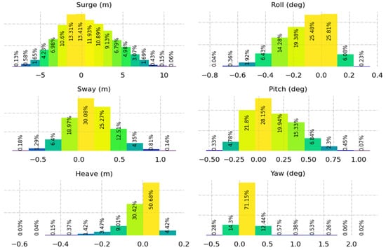
Figure 11.
Histogram of the motions in the 50-year condition.
As for yawing, 98% remains below a half degree, and the maximum is 2.3 degrees. Pitch reaches a maximum of 1.1 degrees while 97% stays lower than 0.5 degrees. The platform heaves mostly between −30 and 20 cm and attains 63 cm at some point. While heaving directly influences the moorings, no slacking or breaking occurs. The peak in the heave (i.e., −63 cm) effect is seen in the mooring line tensions with a minimum of 2544 kN in line T4. The lines T3 and T4, respectively T1 and T2, present roughly identical behavior. The slight discrepancy in their behavior can be related to sway and roll, attaining a maximum of 1.2 m and 0.8 degrees, respectively. Mooring statistics (Figure 12) show that the tensions remain in the acceptable range, and the maximums (i.e., 23,000 kN) are rarely attained.
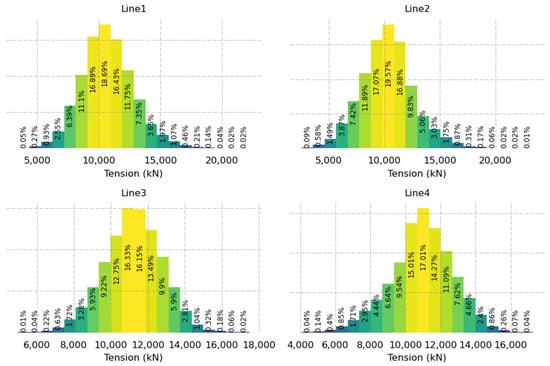
Figure 12.
Histogram of the mooring tensions in the 50-year condition.
5.2. Emergency Shutdown
The shutdown scenarios involve both regular and irregular waves with steady and turbulent wind, respectively. The tests comprise rated and above-rated wind speeds detailed in Table 14. The motion data at the shutdown, including the line tensions, are summarized in Table 21 and Table 22, respectively. The results show that the surge remains below 9 m, so the anchor angle is below 5 degrees. The heave and rotational motions are also restricted to a few centimeters and 0.15 degrees. Regarding the mooring lines, no slacking nor breaking occur. The minimum tension is 6460 kN far enough from the tension limit of a slack line (i.e., 2182 kN). The maximum tension seen in tendon T4 (i.e., 14,670 kN) has a sufficient margin (22,000 kN) till the breaking limit

Table 21.
Motion statistics in emergency shutdown scenario.

Table 22.
Line tension statistics in emergency shutdown scenario.
The emergency shutdown causes a maximum surge of 5 m (Figure 13) which leaves the anchor angle below 5 degrees. While the fault controller may result in high yawing for semis [70], the yaw for the CENTEC-TLP remains limited to 0.2 degrees with the defective controller. In addition, the line tensions (Figure 14) remain in the margin where no slacking nor breaking occur.
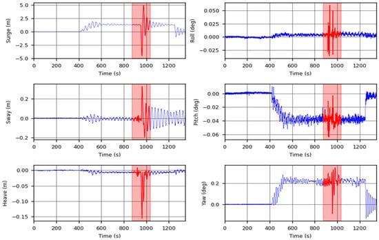
Figure 13.
Motion signals in emergency shutdown case.
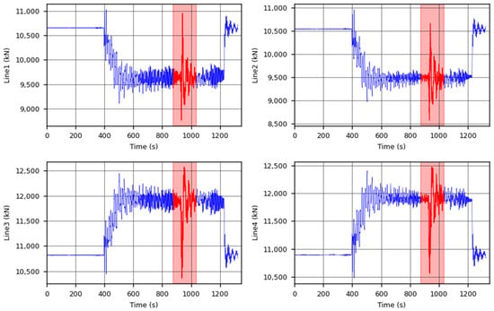
Figure 14.
Mooring tensions signals in the emergency shutdown case.
6. Conclusions
This work presents the hydrodynamic performance of the CENTEC-TLP in operational, extreme, and fault conditions. The objective is achieved by experimental testing of a scaled prototype. The natural frequency of the system validates that the system is replicated with high accuracy. Response amplitude operators obtained from regular wave tests present a minimal system response when subjected to waves. The surging due to steady wind loads remains within acceptable limits.
Stochastic wind and wave tests in operational conditions prove the model’s robustness in these scenarios. The minimal response in pitching emphasizes the advantages of the TLP in capturing the aerodynamic power. In addition, the motions remain restricted in the 50-year extreme condition when examined against the survivability criteria.
The mooring lines’ tensions are also verified as part of the operational and survivability criteria. The tensions remain within the acceptable range, leaving sufficient margins to slack mooring and breaking limits. The same conclusion applies to the emergency shutdown and controller error cases where the motions remain restrained, and the moorings tensions stay within limits.
Author Contributions
Conceptualization, M.H., E.U., A.S.-I. and C.G.S.; methodology, M.H., E.U., A.M.-M., J.M.-S. and A.S.-I.; software, M.H., E.U., F.V., O.P. and J.A.; validation, M.H., A.M.-M., F.V., O.P. and J.A.; formal analysis, M.H. and A.M.-M.; investigation, M.H. and A.M.-M.; resources, A.S.-I. and C.G.S.; data curation, M.H. and A.M.-M.; writing—original draft preparation, M.H.; writing—review and editing, M.H., E.U., A.M.-M., J.A. and C.G.S.; visualization, M.H. and E.U.; supervision, E.U., A.S.-I. and C.G.S.; project administration, C.G.S.; funding acquisition, C.G.S. All authors have read and agreed to the published version of the manuscript.
Funding
This work has been funded by the project ARCWIND—Adaptation and Implementation of Floating Wind Energy Conversion Technology for the Atlantic Region, which is co-financed by the European Regional Development Fund through the Interreg Atlantic Area Programme under contract EAPA 344/2016. The first author has been funded by the project Variable geometry Wave Energy Conversion system for floating platforms (WEC4MUP), which is funded by the Portuguese Foundation for Science and Technology (Fundação para a Ciência e a Tecnologia—FCT) under contract (WEC4MUP_PTDC/EME-REN/0242/2020). The research was also supported by the Spanish Ministry for Science, Innovation and Universities (MCIU) under grant RTI2018-096791-B-C21 ‘‘Hidrodinámica de elementos de amortiguamiento del movimiento de aerogeneradores flotantes’’. This work contributes to the Strategic Research Plan of the Centre for Marine Technology and Ocean Engineering (CENTEC), which is financed by the Portuguese Foundation for Science and Technology (Fundação para a Ciência e Tecnologia—FCT) under contract UIDB/UIDP/00134/2020.
Institutional Review Board Statement
Not applicable.
Informed Consent Statement
Not applicable.
Data Availability Statement
Not applicable.
Conflicts of Interest
The authors declare no conflict of interest.
References
- Díaz, H.; Guedes Soares, C. Review of the Current Status, Technology and Future Trends of Offshore Wind Farms. Ocean Eng. 2020, 209, 107381. [Google Scholar] [CrossRef]
- Energy Data-2020 Edition; Statistical books; Publications Office: Luxembourg, 2020; ISBN 978-92-76-20629-3.
- WindEurope. Wind Energy in Europe-Statistics and the Outlook for 2021–2025; WindEurope: Brussels, Belgium, 2021; p. 36. [Google Scholar]
- Díaz, H.; Serna, J.; Nieto, J.; Guedes Soares, C. Market Needs, Opportunities and Barriers for the Floating Wind Industry. JMSE 2022, 10, 934. [Google Scholar] [CrossRef]
- Bagbanci, H.; Karmakar, D.; Guedes Soares, C. Review of Offshore Floating Wind Turbines Concepts. In Maritime Engineering and Technology; Guedes Soares, C., Garbatov, Y., Sutulo, S., Santos, T.A., Eds.; Taylor & Francis Group: London, UK, 2012; pp. 553–562. [Google Scholar] [CrossRef]
- Uzunoglu, E.; Karmakar, D.; Guedes Soares, C. Floating Offshore Wind Platforms. In Floating Offshore Wind Farms; Castro-Santos, L., Diaz-Casas, V., Eds.; Green Energy and Technology; Springer International Publishing: Cham, Germany, 2016; pp. 53–76. [Google Scholar] [CrossRef]
- Pegalajar-Jurado, A.; Bredmose, H.; Borg, M.; Straume, J.G.; Landbø, T.; Andersen, H.S.; Yu, W.; Müller, K.; Lemmer, F. State-of-the-Art Model for the LIFES50+ OO-Star Wind Floater Semi 10MW Floating Wind Turbine. J. Phys. Conf. Ser. 2018, 1104, 012024. [Google Scholar] [CrossRef]
- Galván, J.; Sánchez-Lara, M.J.; Mendikoa, I.; Pérez-Morán, G.; Nava, V.; Rodríguez-Arias, R. NAUTILUS-DTU10 MW Floating Offshore Wind Turbine at Gulf of Maine: Public Numerical Models of an Actively Ballasted Semisubmersible. J. Phys. Conf. Ser. 2018, 1102, 012015. [Google Scholar] [CrossRef]
- Leroy, V.; Delacroix, S.; Merrien, A.; Bachynski-Polić, E.E.; Gilloteaux, J.-C. Experimental Investigation of the Hydro-Elastic Response of a Spar-Type Floating Offshore Wind Turbine. Ocean Eng. 2022, 255, 111430. [Google Scholar] [CrossRef]
- Robertson, A.N.; Jonkman, J.M.; Goupee, A.J.; Coulling, A.J.; Prowell, I.; Browning, J.; Masciola, M.D.; Molta, P. Summary of Conclusions and Recommendations Drawn From the DeepCwind Scaled Floating Offshore Wind System Test Campaign. In International Conference on Offshore Mechanics and Arctic Engineering; American Society of Mechanical Engineers: New York, NY, USA, 2013. [Google Scholar]
- Salvação, N.; Guedes Soares, C. Wind Resource Assessment Offshore the Atlantic Iberian Coast with the WRF Model. Energy 2018, 145, 276–287. [Google Scholar] [CrossRef]
- Silva, D.; Martinho, P.; Guedes Soares, C. Wave Energy Distribution along the Portuguese Continental Coast Based on a Thirty Three Years Hindcast. Renew. Energy 2018, 127, 1064–1075. [Google Scholar] [CrossRef]
- Salvação, N.; Bentamy, A.; Guedes Soares, C. Developing a New Wind Dataset by Blending Satellite Data and WRF Model Wind Predictions. Renew. Energy 2022, 198, 283–295. [Google Scholar] [CrossRef]
- Díaz, H.; Guedes Soares, C. A Novel Multi-Criteria Decision-Making Model to Evaluate Floating Wind Farm Locations. Renew. Energy 2022, 185, 431–454. [Google Scholar] [CrossRef]
- Uzunoglu, E.; Guedes Soares, C. Hydrodynamic Design of a Free-Float Capable Tension Leg Platform for a 10 MW Wind Turbine. Ocean Eng. 2020, 197, 106888. [Google Scholar] [CrossRef]
- Yang, Y.; Bashir, M.; Wang, J.; Michailides, C.; Loughney, S.; Armin, M.; Hernández, S.; Urbano, J.; Li, C. Wind-Wave Coupling Effects on the Fatigue Damage of Tendons for a 10 MW Multi-Body Floating Wind Turbine. Ocean Eng. 2020, 217, 107909. [Google Scholar] [CrossRef]
- Baita-Saavedra, E.; Cordal-Iglesias, D.; Filgueira-Vizoso, A.; Morató, À.; Lamas-Galdo, I.; Álvarez-Feal, C.; Carral, L.; Castro-Santos, L. An Economic Analysis of An Innovative Floating Offshore Wind Platform Built with Concrete: The SATH® Platform. Appl. Sci. 2020, 10, 3678. [Google Scholar] [CrossRef]
- Filgueira-Vizoso, A.; Castro-Santos, L.; Iglesias, D.C.; Puime-Guillén, F.; Lamas-Galdo, I.; García-Diez, A.I.; Uzunoglu, E.; Díaz, H.; Guedes Soares, C. The Technical and Economic Feasibility of the CENTEC Floating Offshore Wind Platform. J. Mar. Sci. Eng. 2022, 10, 1344. [Google Scholar] [CrossRef]
- Yang, Y.; Bashir, M.; Michailides, C.; Mei, X.; Wang, J.; Li, C. Coupled Analysis of a 10 MW Multi-Body Floating Offshore Wind Turbine Subjected to Tendon Failures. Renew. Energy 2021, 176, 89–105. [Google Scholar] [CrossRef]
- Vittori, F.; Azcona, J.; Eguinoa, I.; Pires, O.; Rodríguez, A.; Morató, Á.; Garrido, C.; Desmond, C. Model Tests of a 10 MW Semi-Submersible Floating Wind Turbine under Waves and Wind Using Hybrid Method to Integrate the Rotor Thrust and Moments. Wind Energy Sci. 2022, 7, 2149–2161. [Google Scholar] [CrossRef]
- Uzunoglu, E.; Guedes Soares, C. A System for the Hydrodynamic Design of Tension Leg Platforms of Floating Wind Turbines. Ocean Eng. 2019, 171, 78–92. [Google Scholar] [CrossRef]
- Tran, T.-T.; Kim, D.-H. The Platform Pitching Motion of Floating Offshore Wind Turbine: A Preliminary Unsteady Aerodynamic Analysis. J. Wind Eng. Ind. Aerodyn. 2015, 142, 65–81. [Google Scholar] [CrossRef]
- Jeon, M.; Lee, S.; Lee, S. Unsteady Aerodynamics of Offshore Floating Wind Turbines in Platform Pitching Motion Using Vortex Lattice Method. Renew. Energy 2014, 65, 207–212. [Google Scholar] [CrossRef]
- Li, Z.; Wen, B.; Dong, X.; Long, X.; Peng, Z. Effect of Blade Pitch Control on Dynamic Characteristics of a Floating Offshore Wind Turbine under Platform Pitching Motion. Ocean Eng. 2021, 232, 109109. [Google Scholar] [CrossRef]
- Tracy, C.H. Parametric Design of Floating Wind Turbines. Ph.D.Thesis, Massachusetts Institute of Technology, Cambridge, MA, USA, 2007. [Google Scholar]
- Kibbee, S.E.; Chianis, J.; Davies, K.B.; Sarwono, B.A. The Seastar Tension-Leg Platform. In Proceedings of the All Days, OTC, Houston, TX, USA, 2 May 1994; p. OTC-7535-MS. [Google Scholar]
- Bachynski, E.E. Design and Dynamic Analysis of Tension Leg Platform Wind Turbines; Norges Teknisk-Naturvitenskapelige Universitet, Fakultet for Ingeniørvitenskap og Teknologi, Institutt for Marin Teknikk: Trondheim, Norway, 2014; ISBN 978-82-326-0097-7. [Google Scholar]
- Han, Y.; Le, C.; Ding, H.; Cheng, Z.; Zhang, P. Stability and Dynamic Response Analysis of a Submerged Tension Leg Platform for Offshore Wind Turbines. Ocean Eng. 2017, 129, 68–82. [Google Scholar] [CrossRef]
- Adam, F.; Myland, T.; Dahlhaus, F.; Großmann, J. GICON®-TLP for Wind Turbines–the Path of Development. In Renewable Energies Offshore; Guedes Soares, C., Ed.; CRC Press: London, UK, 2015; pp. 651–656. [Google Scholar]
- Kibbee, S.; Chianis, J.; Davies, K.; Sarwono, B. A Mini-Platform for Deepwater-the SeaStar TLP; The Society of Naval Architects and Marine Engineers: Houston, TX, USA, 1995. [Google Scholar]
- Oguz, E.; Clelland, D.; Day, A.H.; Incecik, A.; López, J.A.; Sánchez, G.; Almeria, G.G. Experimental and Numerical Analysis of a TLP Floating Offshore Wind Turbine. Ocean Eng. 2018, 147, 591–605. [Google Scholar] [CrossRef]
- Matha, D. Model Development and Loads Analysis of an Offshore Wind Turbine on a Tension Leg Platform with a Comparison to Other Floating Turbine Concepts: April 2009; National Renewable Energy Laboratory (NREL): Golden, CO, USA, 2010; p. 793961, NREL/SR-500-45891. [Google Scholar] [CrossRef]
- ITTC. Recommended Procedures and Guidelines: Model Tests for Offshore Wind Turbines. Recommended Procedures and Guidelines 7.5-02-07-03.8. In Proceedings of the International Towing Tank Conference, Zürich, Switzerland, 13–18 June 2021; p. 19. [Google Scholar]
- Sanchez, R. Technology Readiness Assessment Guide; United States Department of Energy: Washington, DC, USA, 2011; p. 73. [Google Scholar]
- Uzunoglu, E.; Guedes Soares, C. Supervisory System for the Automation of Model Building and Simulations with the Wind Turbine Code FAST. In Progress in Renewable Energies Offshore; Guedes Soares, C., Ed.; Taylor & Francis Group: London, UK, 2016; pp. 627–636. ISBN 978-1-138-62627-0. [Google Scholar]
- Uzunoglu, E.; Guedes Soares, C. Parametric Modelling of Marine Structures for Hydrodynamic Calculations. Ocean Eng. 2018, 160, 181–196. [Google Scholar] [CrossRef]
- Uzunoglu, E.; Guedes Soares, C. Response Dynamics of a Free-Float Capable Tension Leg Platform for a 10 MW Wind Turbine at the Northern Iberian Peninsula. In Developments in Renewable Energies Offshore; Guedes Soares, C., Ed.; Taylor & Francis Group: London, UK, 2020; pp. 408–416. [Google Scholar] [CrossRef]
- Zavvar, E.; Chen, B.Q.; Uzunoglu, E.; Guedes Soares, C. Stress Distribution on the CENTEC-TLP in Still Water and Rated Wind Speed. In Trends in Maritime Technology and Engineering Volume 2; Guedes Soares, C., Santos, T.A., Eds.; Taylor & Francis Group: London, UK, 2022; pp. 519–526. [Google Scholar] [CrossRef]
- Zavvar, E.; Abdelwahab, H.S.; Uzunoglu, E.; Chen, B.Q.; Guedes Soares, C. Numerical Study of the Wave Induced Motions and Loads on the CENTEC-TLP Floating Wind Turbine. In Trends in Renewable Energies Offshore; Guedes Soares, C., Ed.; Taylor & Francis Group: London, UK, 2022; pp. 567–573. [Google Scholar] [CrossRef]
- Hmedi, M.; Uzunoglu, E.; Guedes Soares, C.; Medina-Manuel, A.; Mas-Soler, J.; Abad-Gibert, V.; Souto-Iglesias, A.; Vittori, F.; Pires, O.; Azcona, J. Experimental Analysis of a Free-Float Capable Tension Leg Platform with a 10 MW Turbine. In Trends in Renewable Energies Offshore; Guedes Soares, C., Ed.; Taylor & Francis Group: London, UK, 2022; pp. 549–557. [Google Scholar] [CrossRef]
- Faltinsen, O.M. Sea Loads on Ships and Offshore Structures, Cambridge ocean technology series; 1. paperback ed.; repr.transferred to digital printing; Cambridge University Press: Cambridge, UK, 1999; ISBN 978-0-521-45870-2. [Google Scholar]
- Mas-Soler, J.; Uzunoglu, E.; Bulian, G.; Guedes Soares, C.; Souto-Iglesias, A. An Experimental Study on Transporting a Free-Float Capable Tension Leg Platform for a 10 MW Wind Turbine in Waves. Renew. Energy 2021, 179, 2158–2173. [Google Scholar] [CrossRef]
- Vittori, F.; Pires, O.; Azcona, J.; Uzunoglu, E.; Guedes Soares, C.; Zamora Rodríguez, R.; Souto-Iglesias, A. Hybrid Scaled Testing of a 10MW TLP Floating Wind Turbine Using the SiL Method to Integrate the Rotor Thrust and Moments. In Developments in Renewable Energies Offshore; Guedes Soares, C., Ed.; Taylor & Francis Group: London, UK, 2020; pp. 417–423. [Google Scholar] [CrossRef]
- Pires, O.; Azcona, J.; Vittori, F.; Bayati, I.; Gueydon, S.; Fontanella, A.; Liu, Y.; de Ridder, E.J.; Belloli, M.; van Wingerden, J.W. Inclusion of Rotor Moments in Scaled Wave Tank Test of a Floating Wind Turbine Using SiL Hybrid Method. J. Phys. Conf. Ser. 2020, 1618, 032048. [Google Scholar] [CrossRef]
- Azcona, J.; Bouchotrouch, F.; González, M.; Garciandía, J.; Munduate, X.; Kelberlau, F.; Nygaard, T.A. Aerodynamic Thrust Modelling in Wave Tank Tests of Offshore Floating Wind Turbines Using a Ducted Fan. J. Phys. Conf. Ser. 2014, 524, 012089. [Google Scholar] [CrossRef]
- Hmedi, M.; Uzunoglu, E.; Guedes Soares, C. Review of Hybrid Model Testing Approaches for Floating Wind Turbines. In Trends in Maritime Technology and Engineering Volume 2; Guedes Soares, C., Santos, T.A., Eds.; Taylor & Francis Group: London, UK, 2022; pp. 421–428. [Google Scholar] [CrossRef]
- Otter, A.; Murphy, J.; Pakrashi, V.; Robertson, A.; Desmond, C. A Review of Modelling Techniques for Floating Offshore Wind Turbines. Wind Energy 2021, 25, 831–857. [Google Scholar] [CrossRef]
- Bak, C.; Zahle, F.; Bitsche, R.; Kim, T.; Yde, A.; Henriksen, L.C.; Hansen, M.H.; Blasques., J.P.A.A.; Gaunaa, M.; Natarajan, A. The DTU 10-MW Reference Wind Turbine. In Danish Wind Power Research 2013; 2013; Available online: https://backend.orbit.dtu.dk/ws/portalfiles/portal/55645274/The_DTU_10MW_Reference_Turbine_Christian_Bak.pdf (accessed on 30 October 2022).
- Jonkman, J.; Butterfield, S.; Musial, W.; Scott, G. Definition of a 5-MW Reference Wind Turbine for Offshore System Development; National Renewable Energy Laboratory (NREL): Golden, CO, USA, 2009; p. 75, NREL/TP-500-38060. [Google Scholar]
- Robertson, A.; Jonkman, J.; Masciola, M.; Song, H.; Goupee, A.; Coulling, A.; Luan, C. Definition of the Semisubmersible Floating System for Phase II of OC4; National Renewable Energy Laboratory (NREL): Golden, CO, USA, 2014; p. 1155123, NREL/TP-5000-60601. [Google Scholar]
- Uzunoglu, E.; Guedes Soares, C. An Integrated Design Approach for a Self-Float Capable Tension Leg Platform for Wind Energy. In Developments in Maritime Technology and Engineering; Guedes Soares, C., Santos, T.A., Eds.; Taylor & Francis Group: London, UK, 2021; pp. 673–681. [Google Scholar] [CrossRef]
- Hmedi, M.; Uzunoglu, E.; Guedes Soares, C. Influence of Platform Configuration on the Hydrodynamic Performance of Semi-Submersibles for Offshore Wind Energy. In Trends in Maritime Technology and Engineering Volume 2; Guedes Soares, C., Santos, T.A., Eds.; Taylor & Francis Group: London, UK, 2022; pp. 411–420. [Google Scholar] [CrossRef]
- Silva, D.; Gonçalves, M.; Bentamy, A.; Guedes Soares, C. Assessment of the Use of Scatterometer Wind Data to Force Wave Models in the North Atlantic Ocean. Ocean Eng. 2022, 266, 112803. [Google Scholar] [CrossRef]
- Hmedi, M.; Uzunoglu, E.; Guedes Soares, C. Effect of Geometry Modifications on the Dynamics of a Free-Float Capable Tension Leg Platform. In Trends in Renewable Energies Offshore; Guedes Soares, C., Ed.; Taylor & Francis Group: London, UK, 2022; pp. 575–584. [Google Scholar] [CrossRef]
- Chakrabarti, S.K. Physical Modelling of Offshore Structures. In Handbook of Offshore Engineering; Elsevier: Amsterdam, The Netherlands, 2005; pp. 1001–1054. ISBN 978-0-08-044381-2. [Google Scholar]
- ITTC. Recommended Procedures and Guidelines: Floating Offshore Platform Experiments. Recommended Procedures and Guidelines 7.5-02-07-03.1. In Proceedings of the International Towing Tank Conference, Zürich, Switzerland, 13–18 June 2021; p. 12. [Google Scholar]
- ITTC. Recommended Procedures and Guidelines: Seakeeping Experiments. Recommended Procedures and Guidelines 7.5-02-07-02.1. In Proceedings of the International Towing Tank Conference, Zürich, Switzerland, 13–18 June 2021; p. 33. [Google Scholar]
- ITTC. Recommended Procedures and Guidelines: Passive Hybrid Model Tests of Floating Offshore Structures with Mooring Lines. Recommended Procedures and Guidelines 7.5-02-07-03.5. In Proceedings of the International Towing Tank Conference, Zürich, Switzerland, 13–18 June 2021; p. 8. [Google Scholar]
- Sauder, T.; Chabaud, V.; Thys, M.; Bachynski, E.E.; Sæther, L.O. Real-Time Hybrid Model Testing of a Braceless Semisubmersible Wind Turbine: Part I—The Hybrid Approach. In Proceedings of the Volume 6: Ocean Space Utilization; Ocean Renewable Energy; American Society of Mechanical Engineers: Busan, Republic of Korea, 2016; p. V006T09A039. [Google Scholar]
- Chabaud, V.; Steen, S.; Skjetne, R. Real-Time Hybrid Testing for Marine Structures: Challenges and Strategies. In Proceedings of the Volume 5: Ocean Engineering; American Society of Mechanical Engineers: Nantes, France, 2013. [Google Scholar] [CrossRef]
- Jonkman, J. The New Modularization Framework for the FAST Wind Turbine CAE Tool. In Proceedings of the 51st AIAA Aerospace Sciences Meeting including the New Horizons Forum and Aerospace Exposition, Grapevine, TX, USA, 7–11 January 2013; American Institute of Aeronautics and Astronautics: Grapevine, TX, USA, 2013. [Google Scholar]
- Silva, D.; Bento, A.R.; Martinho, P.; Guedes Soares, C. High Resolution Local Wave Energy Modelling in the Iberian Peninsula. Energy 2015, 91, 1099–1112. [Google Scholar] [CrossRef]
- DNV. Marine Operations and Marine Warranty; DNVGL-STN-001; DNV: Berum, Norway, 2018; p. 676. [Google Scholar]
- DNV. Floating Wind Turbine Structures; DNVGL-ST-F205; DNV: Berum, Norway, 2018; p. 162. [Google Scholar]
- DNV. Global Performance Analysis of Deepwater Floating Structures; DNVGL-RP-F205; DNV: Berum, Norway, 2019. [Google Scholar]
- PI Recommended Practice for Planning, Designing, and Constructing Fixed Offshore Platforms. [American Petroleum In-stitute]. RECOMMENDED PRACTICE 2A-WSD (RP 2A-WSD) TWENTY-FIRST EDITION, DECEMBER. 2000.
- API RP 2T: Planning, Designing, and Constructing Tension Leg Platforms. 2010.
- Chakrabarti, S.K. Handbook of Offshore Engineering; Elsevier: Amsterdam, The Netherlands, 2005; ISBN 978-0-08-044381-2. [Google Scholar]
- ITTC. Recommended Procedures and Guidelines: Analysis Procedure for Model Tests in Regular Waves. Recommended Procedures and Guidelines 7.5-02-07-03.2. In Proceedings of the International Towing Tank Conference, Zürich, Switzerland, 13–18 June 2021; p. 5. [Google Scholar]
- Uzunoglu, E.; Guedes Soares, C. Yaw Motion of Floating Wind Turbine Platforms Induced by Pitch Actuator Fault in Storm Conditions. Renew. Energy 2019, 134, 1056–1070. [Google Scholar] [CrossRef]
- Arnal, V.; Bonnefoy, F.; Gilloteaux, J.-C.; Aubrun, S. Hybrid Model Testing of Floating Wind Turbines: Test Bench for System Identification and Performance Assessment. In Proceedings of the Volume 10: Ocean Renewable Energy, Glasgow, UK, 9–14 June 2019; American Society of Mechanical Engineers: Glasgow, UK, 2019. [Google Scholar] [CrossRef]
- Roddier, D.; Cermelli, C.; Aubault, A.; Weinstein, A. WindFloat: A Floating Foundation for Offshore Wind Turbines. J. Renew. Sustain. Energy 2010, 2, 033104. [Google Scholar] [CrossRef]
Publisher’s Note: MDPI stays neutral with regard to jurisdictional claims in published maps and institutional affiliations. |
© 2022 by the authors. Licensee MDPI, Basel, Switzerland. This article is an open access article distributed under the terms and conditions of the Creative Commons Attribution (CC BY) license (https://creativecommons.org/licenses/by/4.0/).