Article

An Underwater Inductive Power Transfer System with a Compact Receiver and Reduced Eddy Current Loss

1
School of Electrical Engineering, Xi’an Jiaotong University, Xi’an 710049, China
2
Power Department, Xi’an ACTIONPOWER Electric Co., Ltd., Xi’an 710119, China
3
School of Marine Science and Technology, Northwestern Polytechnical University, Xi’an 710072, China
*
Author to whom correspondence should be addressed.
J. Mar. Sci. Eng. 2022, 10(12), 1900; https://doi.org/10.3390/jmse10121900
Submission received: 14 November 2022 / Revised: 25 November 2022 / Accepted: 28 November 2022 / Published: 5 December 2022
(This article belongs to the Topic Sustainable Energy Technology)

Abstract

:
Inductive power transfer (IPT) technology is widely used in autonomous underwater vehicles (AUVs) to achieve safety and flexibility. However, the eddy current loss (ECL) will be generated in the seawater due to the high-frequency alternating current in the transmitter and receiver. An underwater IPT system with a series-none (SN) compensation topology is proposed in this paper to achieve a compact receiver for AUVs and reduce the ECL. The analytical model of the IPT system is built to analyze its transfer performance. The phase difference between the transmitter and receiver current of the SN compensation topology is larger than 90° compared to that of the conventional series-series (SS) topology, which can significantly decrease the magnitude of the electric field caused by coil currents; thus, the eddy current loss is reduced. Moreover, the optimal load resistance of the seawater IPT system is lower than that in the air, and the SN compensation topology has a more compact receiver with no compensation capacitor in the receiving side, which can save the internal space in the AUVs. An experimental prototype based on the SN topology is built, and the experimental results have verified the analysis.

1. Introduction

Inductive power transfer (IPT) has gained popularity nowadays for its nonphysical contact between the power side and load side [1,2]; it is used in different scenarios, such as electric vehicles [3,4,5] and autonomous underwater vehicles (AUVs) [6,7,8,9]. The AUV can be charged wirelessly without direct contact compared to the conventional charging method with watertight connecters, which can effectively improve the navigation distance and operation range of the AUV. In the seawater IPT system, high-frequency coil currents will result in large eddy current loss (ECL) in the seawater, which will decrease the system efficiency [10,11,12]. The ECL, semiconductor loss, winding loss, and ferrite loss are analyzed via the finite element analysis (FEA) method; moreover, the transmission performance is investigated both in air and seawater [13]. A theoretical model is proposed to calculate the ECL, and the resonant frequency is optimized on the basis of this model. However, the ferrite is assumed to be infinite in the calculation process, and thus the compensation correction method is necessary [14]. Then, an eddy current loss calculation model based on a coreless magnetic coupler is proposed, and the switching frequency and resonant frequency are optimized, indicating that the resonant frequency should be lower than the switching frequency in the seawater to maximize the system efficiency [15]. To decrease the ECL in the seawater, a three-coil structure is proposed with one receiver and two transmitters. The ECL generated by the primary coil current can be half reduced [16]. Another method to restrain the ECL is to adopt shielding coils, which can suppress the electromagnetic field emission and improve the system efficiency compared to that without the shielding coils [17].
However, the compact receiver should be considered simultaneously when the eddy current loss is restrained for the receiver size and the weight is restricted on the AUV. To facilitate the integration of the receiver onto the AUV, a compact receiver is required, which means the passive component of the receiver side should be as less as possible. To make the system compact, the resonant frequency should be relatively high. However, high-frequency coil currents will result in large ECL in the seawater, as aforementioned. To achieve the target of compact size without increasing the frequency, the compensation topology is investigated. The series-series (SS) and double-sided inductor–capacitor–capacitor (LCC-LCC) compensation topologies have been widely used for their constant output current characteristic [18,19]. The LCC-LCC topology can achieve the transmitter side protection when the receiver side moves away compared to the SS topology, while the multiple passive electronic components are adopted in the receiver side, which is unfriendly to the compact requirement. The SS topology only has one compensated capacitor in the receiver side, which presents a relatively compact receiver, and the eddy current loss of the IPT system based the SS topology is analyzed [15]. To make the receiver side more compact, the series-none (SN) compensation topology is proposed to work under the strong coupled condition, the receiver of which has no passive components [20]. However, the SN compensation topology has not been used on the seawater IPT system, and the eddy current loss of the system has not been studied yet.
In this paper, an underwater IPT system based on the SN compensation topology is proposed to achieve a compact receiver and reduce the ECL. The analytical model of the IPT system is built to analyze the transfer performance. Moreover, the IPT systems based on the SN and SS compensation topologies are compared under different power level. An experimental prototype with the SN and SS compensation topologies is built to verify the analysis.

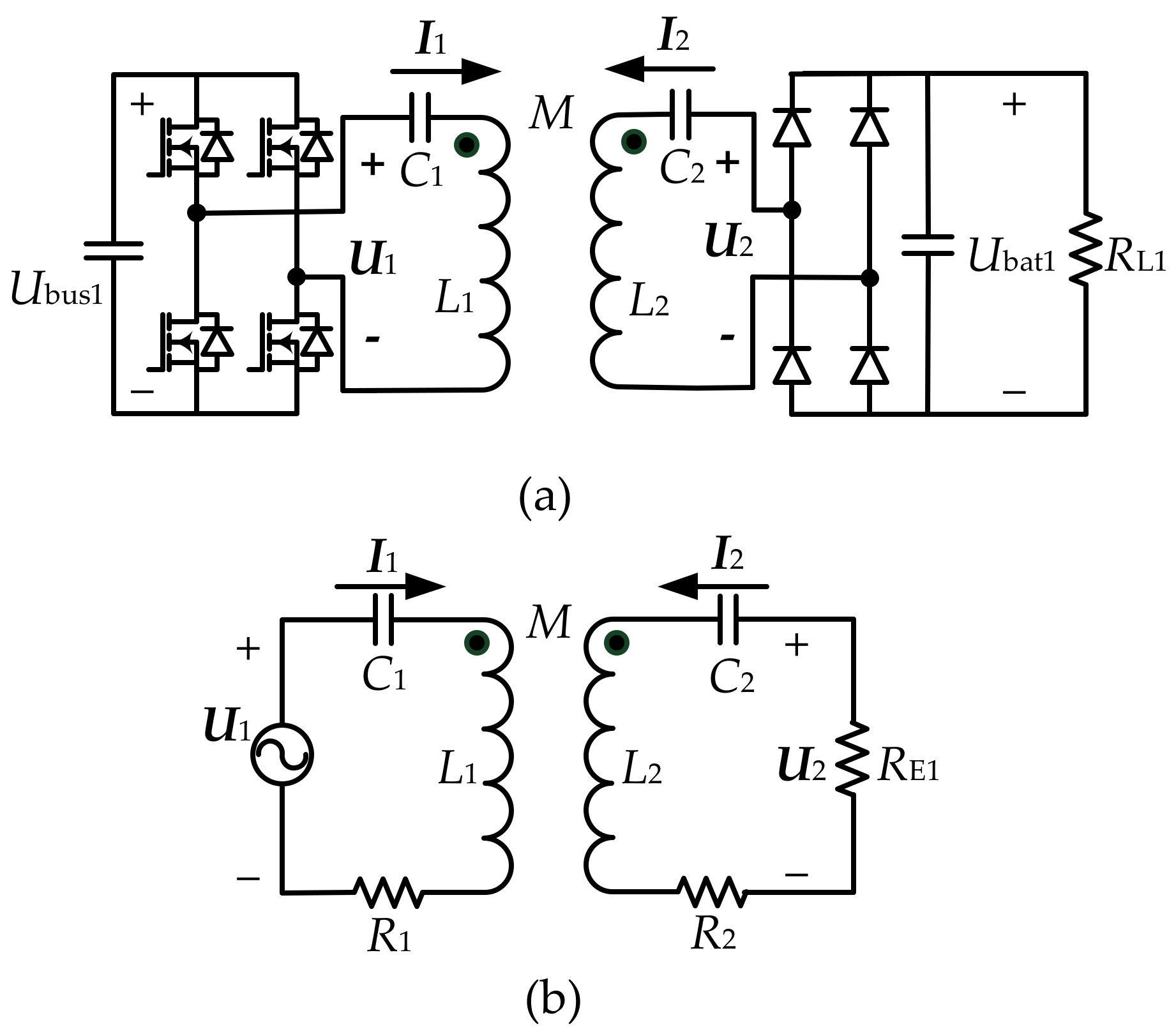
2. Topology and Modeling

The compensation network is introduced to the IPT system to compensate the reactive power and increase the power and efficiency. The SS compensation topology is widely used for its load-independent characteristic [21,22]. To achieve a more compact receiver, the compensation capacitor in the receiver side can be removed, which forms SN compensation topology. In the underwater applications, the gap between the primary and secondary side is in the millimeter range, which means the coupling is strong. Then, the SN topology can be adopted to reduce the size and weight.

2.1. SS Topology

Figure 1 shows the SS-compensated IPT system. Ubus1 and Ubat1 are the input and output dc voltages, U1 and U2 are the input and output ac voltages, I1 and I2 are the transmitter and receiver currents, C1 and C2 are the compensation capacitors, L1 and L2 are the self-inductances, M is the mutual inductance, R1 and R2 are the equivalent resistances of the transmitter side and the receiver side, RL1 is the load resistance, and RE1 = 8 RL12 denotes the equivalent resistance seen before the rectifier. The values in bold font represent their phasor expression.
The circuit is resonant under the following relationship:
ω 0 = 1 L 1 C 1 = 1 L 2 C 2
where ω0 is the resonant angular frequency. Under the resonant condition and according to the Kirchhoff’s law, the following equation can be obtained:
U 1 = R 1 + j ω 0 L 1 + 1 j ω 0 C 1 I 1 + j ω 0 M I 2 U 2 = R 2 + j ω 0 L 2 + 1 j ω 0 C 1 I 2 + j ω 0 M I 1
Substituting (1) into (2) and ignoring the equivalent resistances, we can obtain:
U 1 = j ω 0 M I 2 U 2 = j ω 0 M I 1

2.2. SN Topology

Figure 2 shows the SN-compensated IPT system. Ubus2 and Ubat2 are the input and output dc voltages, U3 and U4 are the input and output ac voltages, I3 and I4 are the transmitter and receiver currents, C1 denotes the compensation capacitor, RL2 is the load resistance, and RE2 = 8 RL22 is the equivalent resistance before the rectifier. The values in bold font represent their phasor expression. In the two topologies, the same magnetic coupler is used to validate the transfer performance. Therefore, the self-inductances, equivalent resistances, and mutual inductance are identical in the two topologies to be expressed with the same variables.
In the SN-compensated IPT system, the compensation capacitor in the transmitter side should be resonant with the leakage inductance of the system, and U3 and U4 are in phase under the resonant state [20]. The resonant frequency can be expressed as:
ω 0 = 1 L r C 3
where Lr denotes the leakage inductance, which is calculated as
L r = 1 k 2 L 1
where k is the coupling coefficient of the IPT system, which is expressed as
k = M L 1 L 2
Under the resonant condition and according to the Kirchhoff’s law, the following equation can be obtained:
U 3 = R 1 + j ω 0 L 1 + 1 j ω 0 C 1 I 3 + j ω 0 M I 4 U 4 = R 2 + j ω 0 L 2 I 4 + j ω 0 M I 3
Ignoring the equivalent resistances, we can obtain:
U 3 = j ω 0 X I 3 + j ω 0 M I 4 U 4 = j ω 0 L 2 I 4 + j ω 0 M I 3
where X represents the transmitter reactance, which is
X = ω 0 L 1 1 ω 0 C 3
Based on (3) and (8), the phasor diagram of the currents and voltages of the SS and SN topologies are depicted in Figure 3.
Figure 3a shows that the phase difference between I1 and I2 is 90°, and U1 and I1 are in phase at the resonant state in the SS compensation topology. Meanwhile, in Figure 3b of the SN compensation topology, U3 leads I3, which is beneficial to realize the zero-voltage switching.
Based on the red triangle in Figure 3b, the following equation can be obtained:
ω 0 M I 3 2 = U 4 2 + ω 0 L 2 I 4 2
Then, the ratio of I3 and I4 can be calculated as:
I 1 I 2 = R E 2 2 ω 0 2 M 2 + L 2 2 M 2
The output power is:
P out = I 4 2 R E 2
Based on (11) and (12), the transfer efficiency can be obtained as:
η = I 4 2 R E 2 I 4 2 R E 2 + I 3 2 R 1 + I 4 2 R 2 = 1 1 + R 1 ω 0 M 2 R E 2 + R 2 + R 1 L 2 2 M 2 1 R E 2
Through the derivation of (13), the transfer efficiency can be maximized when:
R E 2 = ω 0 L 2 2 + ω 0 M 2 R 2 R 1
Then, the maximum efficiency is:
η max = k 2 Q 1 Q 2 k 2 Q 1 Q 2 + 2 k 2 Q 1 Q 2 + Q 2 2
where Q1 and Q2 denote the transmitter and receiver quality factor, which can be expressed as
Q 1 = ω 0 L 1 R 1 , Q 2 = ω 0 L 2 R 2

3. Coil Design

The magnetic coupler of the IPT system for the SS and SN compensation topology is shown in Figure 4, and the corresponding finite element analysis (FEA) model is established. The transmitter and the receiver are designed to be identical. The coil length and width are both 200 mm, and the ferrite length and width are both 220 mm.
Figure 5 shows the coupling coefficient varying with the coil width, which indicates that the coupling coefficient increases with the increasing coil width and then tends to be stable when the coil width is 50 mm. Therefore, the coil width is set to 50 mm. Moreover, the litz wire with 4 mm diameter is adopted in the system, so the turn numbers of the transmitter and receiver are set to 12. The simulated self-inductance and mutual inductance are 58.86 μH and 41.53 μH, respectively.

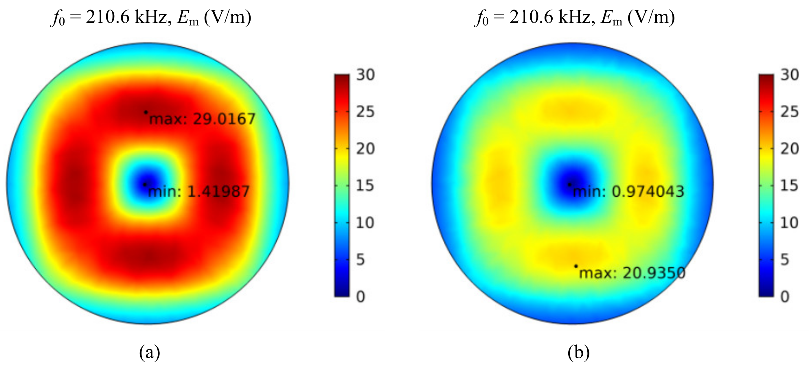
4. Eddy Current Loss in Seawater

The seawater is conductive with a conductivity of 4.5 S/m. High-frequency coil currents will result in large ECL in the seawater, which can be expressed as:
P eddy = V σ E 2 2 d V  
where σ is the conductivity of the seawater, Peddy is the ECL, V denotes the study domain, and E2 is the electric field intensity generated by the primary and secondary coil currents, which should be vector sum of the electric field intensity caused by the primary and secondary coil, respectively. Then, the ECL can be expressed as:
P eddy = V σ E 2 t + E 2 r 2 d V
where E2t and E2r are the electric field intensity caused by primary and secondary coil, respectively. The phase difference of E2t and E2r is nearly equal to that of the transmitter and receiver current. Therefore, if the phase difference is larger than 90°, the vector sum magnitude of E2t and E2r will be decreased, which will eventually decrease the ECL in the seawater. It can be seen in Figure 3b that the phase difference between I3 and I4 is larger than 90°; thus, the ECL will be decreased.
Figure 6 shows the electric field intensity magnitude of the IPT system with SS and SN compensation topology on the intermediate plane between the transmitter and receiver. The output power is 1000 W. It can be seen that the electric field intensity magnitude of the SN topology is smaller than that of the SS topology, which means the eddy current loss will be restrained by the SN topology under the same output power condition. Moreover, Figure 7 shows the eddy current loss density on the intermediate plane between the transmitter and receiver, which indicates that the eddy current loss density of the SN topology is much lower than that of the SS topology. This is because the eddy current loss is square of the electric field intensity magnitude, as can be seen in (17).
If the phase difference between the coil currents is relatively close to 90°, the eddy current loss in (18) can be divided into two parts, which are generated by the primary and secondary current individually:
P eddy = P eddy 1 + P eddy 2 = V σ E 2 t 2 d V   + V σ E 2 r 2 d V
The equivalent resistance of the ECL caused by the primary and secondary current can be expressed as:
R eddy 1 = P eddy 1 I 1 2 R eddy 2 = P eddy 2 I 2 2
Then, the equivalent resistance in the primary and secondary side will become larger, which can be expressed as:
R 1 _ sea = R 1 + R eddy 1 R 2 _ sea = R 2 + R eddy 2
Based on (14) in Section 2.2, the optimal load resistance will shift when the equivalent resistance of the ECL is involved in the seawater IPT system.

5. Experimental Validation

An underwater experimental prototype is established, which is shown in Figure 8. The seawater is placed in the container between the primary side and secondary side. The transmitter and receiver coils are wound by AWG 38 litz wires with 800 strands. The planar coils are used with same dimensions as the transmitter and receiver. The electronic load is used at the voltage mode to emulate the battery. The parameters of the system are listed in Table 1.

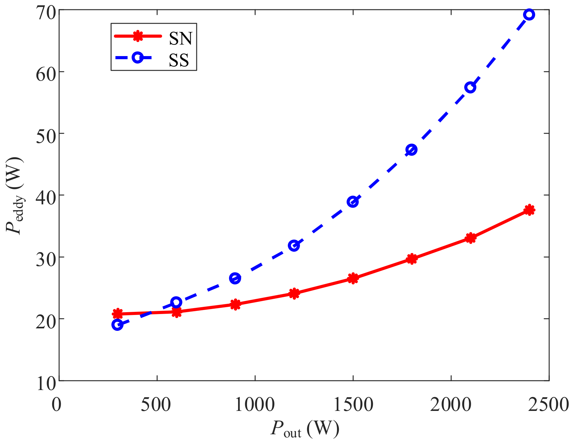
5.1. Comparison of Eddy Current Losses of SN and SS Topology

The experiments are conducted under identical conditions in the seawater and air. Therefore, the other losses of the total losses except the ECL can remain the same during experiments in the air and seawater for the same topology. Then, the ECL in seawater should be the difference between the losses of the IPT system in the two media. Figure 9 shows the relationship of the output power and the ECL, in which SN and SS compensation topologies are compared. It can be seen that the ECL of the SN compensation has a slower rise when the output power increases, which is due to the decrease in the magnitude of the synthesized electric field intensity. However, the ECL of SS compensation increases rapidly for the large synthesized electric field intensity. The experimental result is consistent with the theoretical analysis in Section 4.

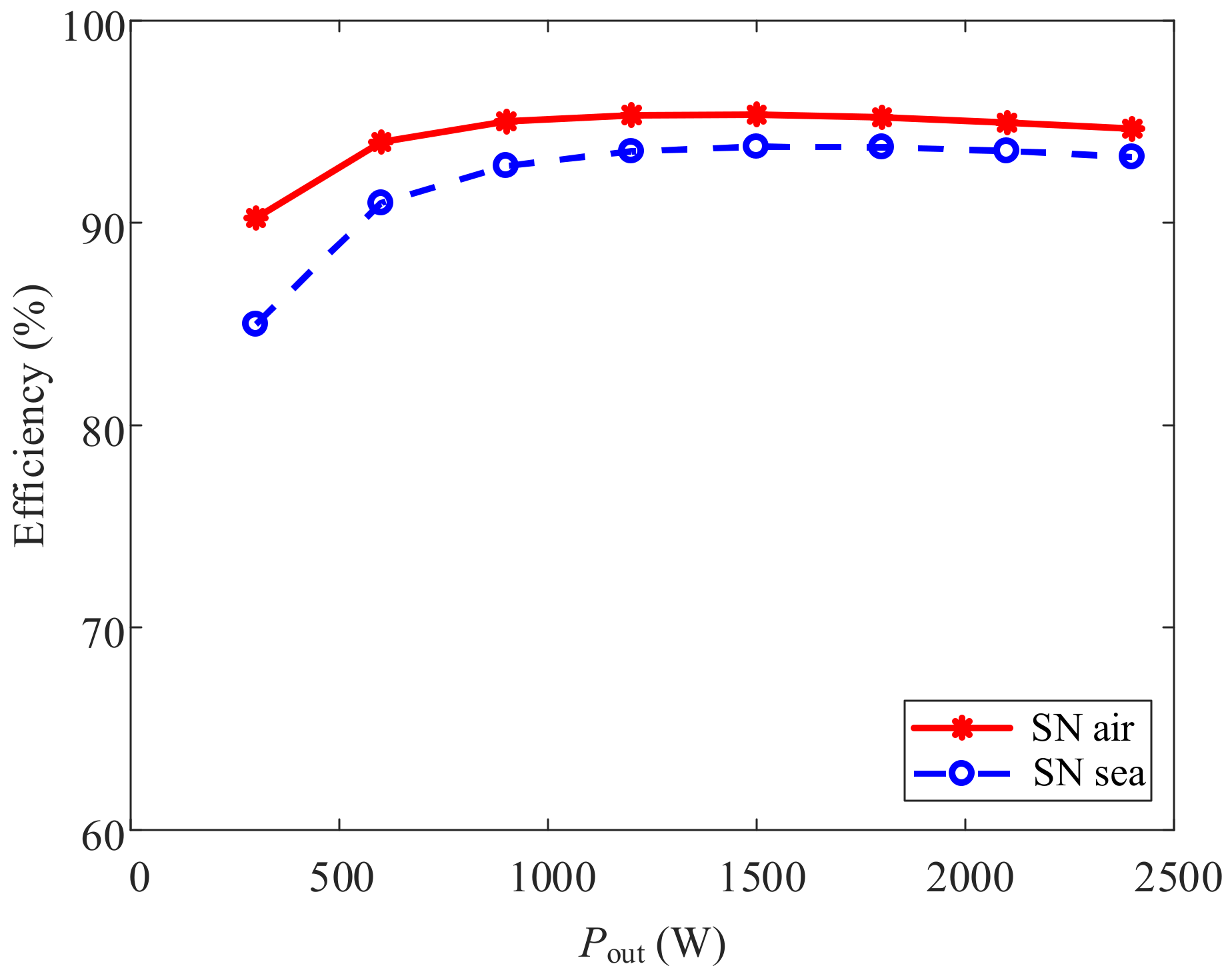
5.2. Transfer Performance of SN Topology

Figure 10 shows the current and voltage waveforms of the SN-compensated IPT system when the input and output dc voltages are 180 V and 280 V, which indicates that the input voltage is in phase with the output voltage. Moreover, the input voltage leads the input current, which means that the zero-voltage switching is realized. The result is consistent with the theoretical analysis in Section 2.2.
Figure 11 shows the system efficiency varying with the output power of the SN-compensated IPT system. The output dc voltage is set to 300 V, and the input voltage is adjusted to regulate the output power from 300 W to 2400 W. It can be seen that dc-dc efficiency increases to a stable value with the increasing output power, and the efficiency in the sea is lower than that in the air because of the ECL in the seawater.
Figure 12 shows the system efficiency varying with the load resistance of the SN compensated IPT system in air and seawater. In this case, the output power is set to 1000 W. It can be seen that both of the dc-dc efficiencies in the air and seawater increase to a maximum value and then decrease with the increasing load resistance. Moreover, the optimal load resistance in the seawater IPT system is smaller than that in the air. For this system, the transmitter current is larger than the receiver current, and the equivalent resistance of the ECL in the primary side is larger than that in the secondary side, which will give rise to the increase in the equivalent resistance ratio of the primary and secondary side. Therefore, based on the theoretical analysis in Section 4, the optimal load resistance will shift to a smaller value.

6. Conclusions

An underwater SN-compensated IPT system is proposed in this paper with a compact receiver and reduced eddy current loss. The phase difference between the transmitter and receiver current of the SN compensation topology is larger than 90° compared to that of the conventional SS topology, which can significantly decrease the vector sum magnitude of the electric field caused by coil currents. Thus, the eddy current loss is reduced to achieve higher efficiency. Moreover, the optimal load resistance of the SN-compensated IPT system in the seawater is lower than that in the air. An underwater SN-compensated IPT prototype has been set up, and the experimental results have verified the theoretical analysis.

Author Contributions

Conceptualization, Z.Y. and C.Z.; methodology, Z.Y. and C.Z.; software, M.W. and Q.H.; validation, Z.Y., C.Z., M.W. and L.Q.; formal analysis, Z.Y. and Q.H.; investigation, Z.Y.; resources, Z.Y.; data curation, Z.Y.; writing—original draft preparation, Z.Y.; writing—review and editing, K.Z. and Y.H.; visualization, Z.Y.; supervision, Z.Y., K.Z. and Y.H.; project administration, Z.Y.; funding acquisition, Z.Y. All authors have read and agreed to the published version of the manuscript.

Funding

This research was funded by the National Natural Science Foundation of China, grant number 52201405 and 52171338, the China Postdoctoral Science Foundation, grant numbers 2020TQ0237 and 2021M702555, and the Power Electronics Science and Education Development Program of Delta Group, grant number DREG2021004.

Institutional Review Board Statement

Not applicable.

Informed Consent Statement

Not applicable.

Data Availability Statement

Not applicable.

Conflicts of Interest

The authors declare no conflict of interest.

References

  1. Mohsan, S.A.H.; Khan, M.A.; Mazinani, A.; Alsharif, M.H.; Cho, H. Enabling Underwater Wireless Power Transfer towards Sixth Generation (6G) Wireless Networks: Opportunities, Recent Advances, and Technical Challenges. J. Mar. Sci. Eng. 2022, 10, 1282. [Google Scholar] [CrossRef]
  2. Deng, J.; Mao, Q.; Wang, W.; Li, L.; Wang, Z.; Wang, S.; Guidi, G. Frequency and Parameter Combined Tuning Method of LCC-LCC Compensated Resonant Converter With Wide Coupling Variation for EV Wireless Charger. IEEE J. Emerg. Sel. Top. Power Electron. 2022, 10, 956–968. [Google Scholar] [CrossRef]
  3. Li, S.; Lu, S.; Mi, C.C. Revolution of Electric Vehicle Charging Technologies Accelerated by Wide Bandgap Devices. Proc. IEEE 2021, 109, 985–1003. [Google Scholar] [CrossRef]
  4. Zhang, Y.; Wu, Y.; Shen, Z.; Pan, W.; Wang, H.; Dong, J.; Mao, X.; Liu, X. Integration of Onboard Charger and Wireless Charging System for Electric Vehicles with Shared Coupler, Compensation, and Rectifier. IEEE Trans. Ind. Electron. 2022, 69, 1–4. [Google Scholar] [CrossRef]
  5. Jiang, Y.; Wang, L.; Wang, Y.; Liu, J.; Li, X.; Ning, G. Analysis, Design, and Implementation of Accurate ZVS Angle Control for EV’s Battery Charging in Wireless High-Power Transfer. IEEE Trans. Ind. Electron. 2019, 66, 4075–4085. [Google Scholar] [CrossRef]
  6. Lin, M.; Li, D.; Yang, C. Design of an ICPT system for battery charging applied to underwater docking systems. Ocean Eng. 2017, 145, 373–381. [Google Scholar] [CrossRef]
  7. Yan, Z.; Zhang, K.; Qiao, L.; Hu, Y.; Song, B. A Multiload Wireless Power Transfer System With Concentrated Magnetic Field for AUV Cluster System. IEEE Trans. Ind. Appl. 2022, 58, 1307–1314. [Google Scholar] [CrossRef]
  8. Sun, P.; Wu, X.; Cai, J.; Wang, X.; Zhang, X.; Liang, Y.; Xiong, Q.; Rong, E. Eddy current loss analysis and frequency optimization design of double-sided LCC-IPT system in seawater environment. Sci. China Technol. Sci. 2022, 65, 407–418. [Google Scholar] [CrossRef]
  9. Yang, L.; Huang, J.; Feng, B.; Zhang, F.; Zhang, Y.; Li, X.; Jian, J.; Wang, Z.; Tong, X. Undersea Wireless Power and Data Transfer System With Shared Channel Powered by Marine Renewable Energy System. IEEE J. Emerg. Sel. Top. Circuits Syst. 2022, 12, 242–250. [Google Scholar] [CrossRef]
  10. Zeng, Y.; Rong, C.; Lu, C.; Tao, X.; Liu, X.; Liu, R.; Liu, M. Misalignment Insensitive Wireless Power Transfer System Using a Hybrid Transmitter for Autonomous Underwater Vehicles. IEEE Trans. Ind. Appl. 2022, 58, 1298–1306. [Google Scholar] [CrossRef]
  11. Zhou, J.; Yao, P.; Chen, Y.; Guo, K.; Hu, S.; Sun, H. Design Considerations for a Self-Latching Coupling Structure of Inductive Power Transfer for Autonomous Underwater Vehicle. IEEE Trans. Ind. Appl. 2021, 57, 580–587. [Google Scholar] [CrossRef]
  12. Liu, P.; Gao, T.; Zhao, R.; Mao, Z. A Novel Conformal Coil Structure Design of Wireless Power Transfer System for Autonomous Underwater Vehicles. J. Mar. Sci. Eng. 2022, 10, 875. [Google Scholar] [CrossRef]
  13. Shi, J.; Li, D.; Yang, C. Design and analysis of an underwater inductive coupling power transfer system for autonomous underwater vehicle docking applications. J. Zhejiang Univ. Sci. C 2014, 15, 51–62. [Google Scholar] [CrossRef]
  14. Zhou, J.; Li, D.; Chen, Y. Frequency selection of an inductive contactless power transmission system for ocean observing. Ocean Eng. 2013, 60, 175–185. [Google Scholar] [CrossRef]
  15. Yan, Z.; Zhang, Y.; Kan, T.; Lu, F.; Zhang, K.; Song, B.; Mi, C.C. Frequency Optimization of a Loosely Coupled Underwater Wireless Power Transfer System Considering Eddy Current Loss. IEEE Trans. Ind. Electron. 2019, 66, 3468–3476. [Google Scholar] [CrossRef]
  16. Zhang, K.; Zhang, X.; Zhu, Z.; Yan, Z.; Song, B.; Mi, C.C. A New Coil Structure to Reduce Eddy Current Loss of WPT Systems for Underwater Vehicles. IEEE Trans. Veh. Technol. 2019, 68, 245–253. [Google Scholar] [CrossRef]
  17. Wang, Y.; Song, B.; Mao, Z. Application of Shielding Coils in Underwater Wireless Power Transfer Systems. J. Mar. Sci. Eng. 2019, 7, 267. [Google Scholar] [CrossRef] [Green Version]
  18. Song, K.; Li, Z.; Jiang, J.; Zhu, C. Constant Current/Voltage Charging Operation for Series-Series and Series-Parallel Compensated Wireless Power Transfer Systems Employing Primary-Side Controller. IEEE Trans. Power Electron. 2018, 33, 8065–8080. [Google Scholar] [CrossRef]
  19. Li, W.; Zhao, H.; Kan, T.; Mi, C. Inter-operability considerations of the double-sided LCC compensated wireless charger for electric vehicle and plug-in hybrid electric vehicle applications. In Proceedings of the 2015 IEEE PELS Workshop on Emerging Technologies: Wireless Power (2015 WoW), Daejeon, Republic of Korea, 5–6 June 2015; pp. 1–6. [Google Scholar]
  20. Zhang, Y.; Kan, T.; Yan, Z.; Mao, Y.; Wu, Z.; Mi, C.C. Modeling and Analysis of Series-None Compensation for Wireless Power Transfer Systems with a Strong Coupling. IEEE Trans. Power Electron. 2019, 34, 1209–1215. [Google Scholar] [CrossRef]
  21. Aditya, K.; Williamson, S.S. Design Guidelines to Avoid Bifurcation in a Series–Series Compensated Inductive Power Transfer System. IEEE Trans. Ind. Electron. 2019, 66, 3973–3982. [Google Scholar] [CrossRef]
  22. Chen, Y.; He, S.; Yang, B.; Chen, S.; He, Z.; Mai, R. Reconfigurable Rectifier-Based Detuned Series-Series Compensated IPT System for Anti-Misalignment and Efficiency Improvement. IEEE Trans. Power Electron. 2022, 38, 2720–2729. [Google Scholar] [CrossRef]
Figure 1. The SS-compensated IPT system. (a) The circuit topology; (b) the equivalent circuit.
Jmse 10 01900 g001
Figure 2. The SN-compensated IPT system. (a) The circuit topology; (b) the equivalent circuit.
Jmse 10 01900 g002
Figure 3. The phasor diagram of the currents and voltages. (a) SS topology; (b) SN topology.
Jmse 10 01900 g003
Figure 4. The magnetic coupler of the IPT system.
Jmse 10 01900 g004
Figure 5. The coupling coefficient varying with the coil width.
Jmse 10 01900 g005
Figure 6. The electric field intensity magnitude of the IPT system. (a) SS topology; (b) SN topology.
Jmse 10 01900 g006
Figure 7. The loss density distribution of the IPT system. (a) SS topology; (b) SN topology.
Jmse 10 01900 g007
Figure 8. Experimental prototype.
Jmse 10 01900 g008
Figure 9. The ECL varying with the output power.
Jmse 10 01900 g009
Figure 10. The voltage and current waveforms of the system.
Jmse 10 01900 g010
Figure 11. System efficiency varying with Pout.
Jmse 10 01900 g011
Figure 12. System efficiency varying with the load resistance.
Jmse 10 01900 g012
Table 1. System parameters.
ParametersDefinitionsValue
L1Transmitter self-inductance58.61 μH
L2Receiver self-inductance57.03 μH
MMutual inductance between the transmitter and receiver40.88 μH
N1Transmitter turn number12
N2Receiver turn number12
kCoupling coefficient0.707
f0Resonant frequency210.6 kHz
LrLeakage inductance29.31 μH
C1Transmitter compensation capacitor of SS topology9.8 nF
C2Receiver compensation capacitor of SS topology10.0 nF
C3Transmitter compensation capacitor of SN topology19.5 nF
Coil dimension200 mm × 200 mm
Publisher’s Note: MDPI stays neutral with regard to jurisdictional claims in published maps and institutional affiliations.

