Article

Mathematical Model of an Offshore Friction Pile in Multilayered Saturated Soils

College of Transportation, Shandong University of Science and Technology, Qingdao 266000, China
*
Author to whom correspondence should be addressed.
J. Mar. Sci. Eng. 2022, 10(12), 1886; https://doi.org/10.3390/jmse10121886
Submission received: 2 November 2022 / Revised: 22 November 2022 / Accepted: 24 November 2022 / Published: 4 December 2022
(This article belongs to the Special Issue Design and Analysis of Offshore Structures)

Abstract

:
In this paper, an analytical methodology is proposed to study the vibration of an offshore friction pile embedded in multilayered saturated viscoelastic soils by combining Biot’s saturated wave propagation theory, Novak’s plane-strain model, and the fictitious saturated soil pile model. The corresponding semi-analytical solution for the dynamic response of the pile is developed considering the heterogeneity, porosity, and limited thickness of the soils. The approach and relevant solution presented are validated by comparisons with existing solutions. Furthermore, numerical instances are used to investigate the influences of the porosity and heterogeneity of the saturated soils around and beneath the pile on the vibration of the pile. The findings from this paper provide a theoretical reference for a comprehensive understanding of the wave propagation characteristics of a friction pile embedded in heterogeneous saturated soil with limited thickness.

1. Introduction

In recent decades, pile foundations have been extensively used to support various offshore super-structures, such as offshore platforms and wind turbines, due to their large capacity. These structures are commonly subjected to vertical dynamic loading. Therefore, research on the vibration of the pile–soil system has attracted wide attention [1,2,3,4,5,6]. It is important to carefully choose one of the various computational models of soils around and beneath a pile when examining the vibration of the pile–soil system. For soil around the pile, the simplified discrete spring–dashpot model, named the Winkler model, has been extensively adopted due to its understandability and convenience [7,8,9]. Nevertheless, this discrete model ignores the wave propagation effect in soil [10,11,12]. On this basis, Novak [13] presented a vertical thin layer method to introduce the wave propagation effect in the soil around a pile. Then, Nogami et al. [14] further considered the vertical and radial wave propagation effect of vertical displacement that occurs in soil and proposed a three-dimensional continuum (3D-C) model. Subsequently, Wu et al. [15] developed a true 3D-C model by taking the vertical and radial displacements of soil into account.
As for the soil beneath a pile, the commonly used models consist of the fixed-support model [16] and the Kelvin–Voigt model [17]. When the boundary conditions beneath the pile can be regarded as end-bearing, the fixed-support model can feasibly address the vibration problems of a pile. Conversely, the Kelvin–Voigt model is mainly applied to study the vibration of friction piles [18,19]. However, this model ignores the influence of the wave propagation effect in soil beneath piles on the vibration of friction piles, which cannot be roughly disregarded [20]. Therefore, Muki et al. [21] developed an elastic half-space model to consider the specific effect of soil beneath piles. Although it is considered a potent approach, the major deficiency of the half-space model is that it cannot take the influences of the thickness and inhomogeneity of the soil beneath the pile into account. In this regard, Wu et al. [22] regarded the pile end soil as a one-dimensional rod, named the fictitious soil pile (FSP) [23], and introduced the perfect coupling conditions for the pile and the soils around and beneath the pile to solve this problem. On this basis, Wang et al. [24] and Lü et al. [25] applied this FSP model to discuss the effect of the thickness of pile end soil on the vibration of friction piles.
In the aforementioned analytical models, the porosity of the soil is roughly ignored. However, as a typical multi-phase media, the porous fluid within the soil significantly affects the vertical vibration of the saturated soil–pile system [26,27]. Concerning this problem, the classical wave propagation theory for saturated soil proposed by Biot has been introduced to study the pile and saturated soil vibration problem [28]. Senjuntichai [29] and Hasheminejad [30] were the pioneers in this field and analytically solved the vibration problems posed by holes in saturated soils by applying the potential function method. Subsequently, Li et al. [31], Liu [32], and Zheng [33] employed a similar method to solve the vibration equations of saturated soils and then derived the corresponding analytical solutions by considering the coupling conditions of the soil and pile, where the soil beneath pile was simplified by using the Kelvin–Voigt model. Furthermore, to consider the porosity of soil beneath piles, Zeng et al. [34] and Militano et al. [35] developed a saturated half-space model by combining Muki’s model and Biot’s theory.
From the literature review, it can be found that the effect of heterogeneity on the vibration of friction piles in saturated soils has not been considered. Based on the advantages of the FSP model, this paper extends the single-phase FSP model to two-phase soils (saturated soils), where the limited thickness and heterogeneity of saturated soils are both considered. Compared with existing methods, the proposed methodology can account for the vertical heterogeneity, porosity, and wave propagation effect in soils around and beneath piles. The rationality of the developed method and corresponding solutions are verified by comparing them with those acquired from previous theoretical methods. Subsequently, numerical instances are conducted to study the effects of the porosity and heterogeneity of soils on the vibration of the friction pile.

2. Methodology

2.1. The Simplified Mechanical Model

The mathematical model adopted in this paper is shown in Figure 1. The vibration characteristics of the pile and fictitious saturated soil pile (FSSP) are represented by the Euler–Bernoulli theory. The m layers of piles and soils are numbered 1,…, j,…, n, n + 1,…, k, …, m from bottom to top. The depths and thicknesses of the j-th and k-th soil layers are l j and h j , and l k and h k , respectively. The length of the FSSP and solid pile are H FSSP and H P , respectively. The thickness of soils above the rigid base is H. The radius of the k-th pile is r k . P ˜ e i ω t is the force at the pile head. P ˜ and ω are the amplitude and circular frequency of the excitation, respectively. P ˜ is a real number. i = 1 denotes the imaginary unit. The friction between the j-th FSSP segment and soil layer beneath the pile is τ ˜ j e i ω t . Similarly, the friction between the k-th pile segment and soil layer around the pile is τ ˜ k e i ω t . τ ˜ j and τ ˜ k are the amplitudes of the corresponding friction.
The assumptions adopted in this simplified mathematical model are shown as follows:
(1)
The soil consists of a series of thin layers of independent saturated media. Specifically, the permeability of soil beneath pile is low.
(2)
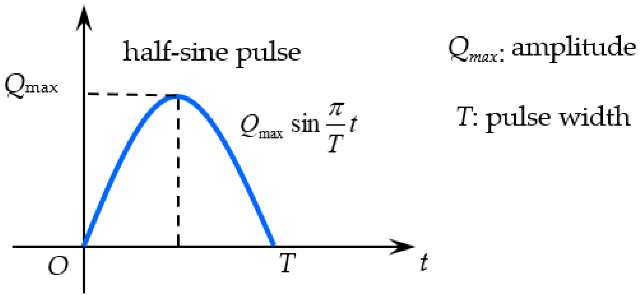
As shown in Figure 2 [8], the excitation at the solid pile head is in the form of harmonic pressure ( P ˜ e i ω t = Q max sin π T t ), which is the most commonly used excitation type in pile integrity tests. The toe of the FSSP is simplified as a fixed boundary.
(3)
The boundary of the solid pile and the FSSP is fully bonded.
(4)
The vibrations of the pile and soils are small. The sliding at the interface of pile and soil is ignored.
The mathematical model is proposed for the investigation of vertical wave propagation in an offshore friction pile in multilayered saturated soils, which is the theoretical basis for pile integrity testing in practice. The most commonly used excitation for pile integrity testing is the half-sine pulse. Therefore, the half-sine pulse equation is used in this manuscript.

2.2. Definite Problems

According to Biot’s theory and Novak’s model, the j-th and the k-th soil layer are controlled by:
G j ( 2 r 2 + 1 r r ) u j = ρ j 2 u j t 2 + ρ j f 2 w j t 2
ρ j f 2 u j t 2 + ρ j f N j 2 w j t 2 + b j w j t = 0
G k ( 2 r 2 + 1 r r ) u k = ρ k 2 u k t 2 + ρ k f 2 w k t 2
ρ k f 2 u k t 2 + ρ k f N k 2 w k t 2 + b k w k t = 0
where u j and u k are the vertical displacements of the soil skeletons. w j and w k are the vertical displacements of the fluid relative to the soil skeleton of the j-th and k-th soil layers, respectively. G j , ρ j , ρ j f , N j , b j , G k , ρ k , ρ k f , N k , and b k are the physical parameters of the j-th and k-th soil layers, the definitions of which can be found in the work of Zheng et al. [33].
The relationships between the physical parameters of Equations (1) and (2) as well as Equations (3) and (4) are given as follows:
ρ j = 1 N j ρ j S + N j ρ j f ρ k = 1 N k ρ k S + N k ρ k f b j = η j / k j b k = η k / k k k j = η j k j D / ρ j f g k k = η k k k D / ρ k f g G j = G j ( 1 + 2 ξ j i ) G k = G k ( 1 + 2 ξ k i )
where ρ j S , η j , k j , k j D , G j and ξ j are the density of the soil grains, viscosity coefficient, hydraulic conductivity, permeability, shear modulus, and damping ratio, respectively, of the j-th soil layer. ρ k S , η k , k k , k k D , G k and ξ k are the relevant parameters of the k-th soil layer.
The j-th FSSP segment [36] is controlled by:
( λ j + 2 G j + α j 2 M j ) 2 u j FSSP z 2 = ρ j 2 u j FSSP t 2
where u j FSSP is the displacement of the j-th FSSP. λ j = 2 ν j G j / ( 1 2 ν j ) , ν j is the Poisson’s ratio. α j = 1 K j b / K j S . M j = ( K j S ) 2 / K j d K j b . K j S , K j f and K j b denote the bulk moduli of the soil grains, fluid, and soil skeleton, respectively.
On this basis, by further introducing the resistance of the soil beneath the pile at the interface of the soil and FSSP, Equation (6) can be rewritten as:
E j FSSP 2 u j FSSP z 2 ρ j 2 u j FSSP t 2 + 2 π r j A j FSSP τ ˜ j e i ω t = 0
where E j FSSP = λ j + 2 G j + α j 2 M j , r j is the radius of the j-th FSSP segment, and A j FSSP = π r j 2 .
The k-th solid pile segment is controlled by:
E k P 2 u k P z 2 ρ k P 2 u k P t 2 + 2 π r k A k P τ ˜ k e i ω t = 0
where u k P is the vertical displacement of the k-th pile. E k P , ρ k P and A k P denote the elastic modulus, density, and cross-sectional area, respectively. A k P = π r k 2 .
When the excitation is harmonic, the displacements of the pile and soil satisfy the following equations:
u j r , t = u ˜ j r e i ω t w j r , t = w ˜ j r e i ω t
u k r , t = u ˜ k r e i ω t w k r , t = w ˜ k r e i ω t
u j FSSP ( z , t ) = u ˜ j FSSP ( z ) e i ω t
u k P ( z , t ) = u ˜ k P ( z ) e i ω t
where u ˜ j r , w ˜ j r , u ˜ k r and w ˜ k r are the amplitudes of the corresponding displacement for saturated soils. u ˜ j FSSP and u ˜ k P ( z ) are the amplitudes of the corresponding displacement for the FSSP and solid pile, respectively.
According to Equations (9) and (10), Equations (1)–(4) can be rewritten as:
G j ( 2 r 2 + 1 r r ) u ˜ j + ρ j ω 2 u ˜ j + ρ j f ω 2 w ˜ j = 0
ρ j f ω 2 u ˜ j ρ j f N j ω 2 w ˜ j + b j i ω w ˜ j = 0
G k ( 2 r 2 + 1 r r ) u ˜ k + ρ k ω 2 u ˜ k + ρ k f ω 2 w ˜ k = 0
ρ k f ω 2 u ˜ k ρ k f N k ω 2 w ˜ k + b k i ω w ˜ k = 0
The substitution for Equations (11) and (12) into Equations (7) and (8), respectively, yields:
E j FSSP 2 u ˜ j FSSP z 2 + ρ j ω 2 u ˜ j FSSP + 2 π r j A j FSSP τ ˜ j = 0
E k P 2 u ˜ k P z 2 + ρ k P ω 2 u ˜ k P + 2 π r k A k P τ ˜ k = 0

2.3. Boundary Conditions

The boundary conditions of this vibration problem can be listed as:
The soil displacements diminish at infinity, namely:
lim r u ˜ j = 0
lim r u ˜ k = 0
The boundary conditions of the pile head and FSSP toe are given as:
u ˜ m P z z = 0 = P ˜ E m P A m P
u ˜ 1 FSSP z = H = 0
The conditions of the j-th and j + 1-th FSSP as well as the k-th and k + 1-th pile are given as:
u ˜ j FSSP z = h j = u ˜ j + 1 FSSP z = h j
E j FSSP u ˜ j FSSP z = E j + 1 FSSP u ˜ j + 1 FSSP z z = h j
u ˜ k P z = h k = u ˜ k + 1 P z = h k
E k P A k P u ˜ k P z = E k + 1 P A k + 1 P u ˜ k + 1 P z z = h k
The conditions of the FSSP and pile are given as:
u ˜ n FSSP z = H P = u ˜ n + 1 P z = H P
E n FSSP A n FSSP u ˜ n FSSP z = E n + 1 P A n + 1 P u ˜ n + 1 P z z = H P
The coupling conditions of the saturated soil layers and pile segments are:
u ˜ j = u ˜ j FSSP r = r j
u ˜ k = u ˜ k P r = r k

3. Solutions for the Definite Problems

3.1. Soils Solutions

Substituting Equations (14) and (16) into Equations (13) and (15) gives:
( 2 r 2 + 1 r r ) u ˜ j q j 2 u ˜ j = 0
( 2 r 2 + 1 r r ) u ˜ k q k 2 u ˜ k = 0
where q j 2 = ρ j ω 2 G j N j ( ρ j f ) 2 ω 4 G j ( ρ j f ω 2 + i N j b j ω ) , q k 2 = ρ k ω 2 G k N k ( ρ k f ) 2 ω 4 G k ( ρ k f ω 2 + i N k b k ω ) .
The general solutions of Equations (31) and (32) can be easily given as:
u ˜ j = A j K 0 ( q j r ) + B j I 0 ( q j r )
u ˜ k = A k K 0 ( q k r ) + B k I 0 ( q k r )
where I 0 ( ) (1-kind, 0-order) and K 0 ( ) (2-kind, 0-order) are Bessel functions [32]; A j , B j , A k and B k are undetermined coefficients.
By substituting Equations (33) and (34) into the boundary condition Equations (19) and (20), respectively, we can get B j = B k = 0 . Then, Equations (33) and (34) can be rewritten as:
u ˜ j = A j K 0 ( q j r )
u ˜ k = A k K 0 ( q k r )

3.2. Solutions for the FSSP

The substitution of Equation (35) into Equation (29) gives:
A j = u ˜ j FSSP K 0 ( q j r j )
Therefore, the shear stress of the j-th soil is given as:
τ ˜ j = G j u ˜ j r r = r j = G j q j K 1 ( q j r j ) u ˜ j FSSP K 0 ( q j r j )
Furthermore, substituting Equation (38) into Equation (17) yields:
2 u ˜ j FSSP z 2 β j 2 u ˜ j FSSP = 0
where β j 2 = ρ j ω 2 E j FSSP + G j 2 π r j q j K 1 ( q j r j ) E j FSSP A j FSSP K 0 ( q j r j ) .
The solution of Equation (39) is given as:
u ˜ j FSSP = C j e β j z + D j e β j z
where C j and D j are undetermined coefficients.
When j = 1, substituting Equation (40) into Equation (22) gives:
C 1 / D 1 = γ 1 = e β 1 H / e β 1 H
Thus, the vertical displacement impedance function (VDIF) of the first FSSP segment head can be given as:
Z 1 FSSP = E 1 FSSP A 1 FSSP u ˜ 1 FSSP / z z = h 1 u ˜ 1 FSSP z = h 1 = E 1 FSSP A 1 FSSP γ 1 β 1 e β 1 h 1 β 1 e β 1 h 1 γ 1 e β 1 h 1 + e β 1 h 1
By introducing the relations shown in Equations (23) and (24), the VDIF of the j-th and j + 1-th FSSP segments can be expressed as:
Z j + 1 FSSP = E j + 1 FSSP A j + 1 FSSP γ j + 1 β j + 1 e β j + 1 h j + 1 β j + 1 e β j + 1 h j + 1 γ j + 1 e β j + 1 h j + 1 + e β j + 1 h j + 1
where γ j + 1 = β j + 1 e β j + 1 h j Z j FSSP e β j + 1 h j / E j + 1 FSSP A j + 1 FSSP β j + 1 e β j + 1 h j + Z j FSSP e β j + 1 h j / E j + 1 FSSP A j + 1 FSSP .
By performing the transfer function recursion method, the VDIF at the FSSP head can be expressed as:
Z n FSSP = E n FSSP A n FSSP u ˜ n FSSP / z z = H P u ˜ n FSSP z = H P = E n FSSP A n FSSP γ n β n e β n h n β n e β n h n γ n e β n h n + e β n h n
where γ n = β n e β n h n 1 Z n 1 FSSP e β n h n 1 / E n FSSP A n FSSP β n e β n h n 1 + Z n 1 FSSP e β n h n 1 / E n FSSP A n FSSP .

3.3. Solutions for Solid Pile

By substituting Equation (36) into Equation (30), we can obtain:
A k = u ˜ k P K 0 ( q k r k )
Hence, the shear stress of the k-th soil can be obtained as:
τ ˜ k = G k u ˜ k r r = r k = G k q k K 1 ( q k r k ) u ˜ k P K 0 ( q k r k )
Furthermore, substituting Equation (46) into Equation (18) gives:
2 u ˜ k P z 2 β k 2 u ˜ k P = 0
where β k 2 = ρ k P ω 2 E k P + G k 2 π r k q k K 1 ( q k r k ) E k P A k P K 0 ( q k r k ) .
The solution of Equation (47) is achieved as:
u ˜ k P = C k e β k z + D k e β k z
where C k and D k are undetermined coefficients.
When j = n and k = n + 1, substituting Equations (40) and (48) into Equations (27) and (28) gives:
E n FSSP A n FSSP u ˜ n FSSP / z z = H P u ˜ n FSSP z = H P = E n + 1 P A n + 1 P u ˜ n + 1 P / z z = H P u ˜ n + 1 P z = H P = C n + 1 D n + 1 β n + 1 e β n + 1 H P + β n + 1 e β n + 1 H P C n + 1 D n + 1 e β n + 1 H P + e β n + 1 H P
Then, by substituting Equation (44) into Equation (49), it yields:
γ n + 1 = C n + 1 D n + 1 = β n + 1 e β n + 1 H P Z n FSSP e β n + 1 H P / E n + 1 P A n + 1 P β n + 1 e β n + 1 H P + Z n FSSP e β n + 1 H P / E n + 1 P A n + 1 P
Thus, the VDIF of the n + 1-th pile head is given as:
Z n + 1 P = E n + 1 P A n + 1 P γ n + 1 β n + 1 e β n + 1 h n + 1 β n + 1 e β n + 1 h n + 1 γ n + 1 e β n + 1 h n + 1 + e β n + 1 h n + 1
By introducing the relations shown in Equations (25) and (26), the VDIF at the head of the k-th and k + 1-th pile can be expressed as:
Z k + 1 P = E k + 1 P A k + 1 P γ k + 1 β k + 1 e β k + 1 h k + 1 β k + 1 e β k + 1 h k + 1 γ k + 1 e β k + 1 h k + 1 + e β k + 1 h k + 1
where γ k + 1 = β k + 1 e β k + 1 h k Z k P e β k + 1 h k / E k + 1 P A k + 1 P β k + 1 e β k + 1 h k + Z k P e β k + 1 h k / E k + 1 P A k + 1 P .
By performing the transfer function recursion method, the VDIF of the pile head is given as:
Z m P = E m P A m P β m γ m 1 γ m + 1
where γ m = β m e β m h m 1 Z m 1 P e β m h m 1 / E m P A m P β m e β m h m 1 + Z m 1 P e β m h m 1 / E m P A m P .
Hence, the dynamic impedance (DI) of the pile at its head, K d , can be expressed as:
K d = Z m P = K r + i K i
where K r and K i are the corresponding dynamic stiffness (DS) and dynamic damping (DD), respectively.
The solution for the velocity in the frequency domain (VFD) at the pile head can be given as:
H v ( i ω ) = i ω H u ( ω ) = i ω Z m P = i ω E m P A m P β m γ m + 1 γ m 1
When the excitation is P ˜ e i ω t = Q max sin π T t 0 t T , the solution for the velocity in the time domain (VTD) can be calculated by conducting inverse Fourier transformation [33]:
v ( t ) = I F T [ H v π T π 2 T 2 ω 2 ( 1 + e i ω T ) ]
where v ( t ) is velocity.

4. Results and Discussions

As has been done in existing research [31,32,33], the default mechanical parameters adopted in this section are listed as:
E k P = 25   GPa , ρ k P = 2500   kg m 3 , r k P = 0.5   m , H P = 10   m , H FSSP = 1   m , ρ j S = ρ k S = 2700   kg m 3 , ρ j f = ρ k f = 1000   kg m 3 , k j D = 10 10   m s - 1 , k k D = 10 6   m s - 1 , N j = N k = 0.1 , η j = η k = 10 - 2   N s m - 2 , G j = G k = 0.1 GPa , ξ j = ξ k = 0.05 , v j = v k = 0.3 , K j S = 36 GPa , K j f = 2 GPa .
To consider the layers of soils, the saturated soils around and beneath the pile are divided into three and five layers. The parameters of the soil layers are listed in Table 1.

4.1. Verification of the Present Method

The acquired solution for the DI shown in Equation (36) can be reduced to represent the dynamic characteristics of a pile in single-phase media by setting ρ j f , ρ k f 0 and M j 0 [28]. Wu et al. [15] gave the solution for the DI by using the FSP model, where the soils are considered single-phase media. To verify the validity of the proposed analytical method, the reduced form of the DI calculated by Equation (36) is compared with the DI from Wu’s [15] existing research using the same parameter system. As is shown in Figure 3, the proposed solution for the DI with various pile lengths, HP, agrees well with that presented by Wu et al. [15]. Hence, the present model and relevant solutions can be validated with the comparison above.

4.2. Comparative Analyses

To clarify the advantage of the present methodology over the previous models, the comparison between the solutions derived from the FSSP model and existing solutions for the dynamic response of a pile is performed in Figure 4. The FSSP model presented in this paper can both take the effect of porosity and wave propagation for soils beneath a pile into account, while the FSP model [37] ignores the effect of porosity on the soil and the end-bearing pile model in saturated soil proposed by Li et al. [31] ignores the wave propagation of soil beneath pile. As can be seen in Figure 4a, the resonance frequency of the VFD of the developed FSSP model is greater than that of the FSP model. Moreover, this difference gradually diminishes with the rise in frequency. According to this phenomenon, one of the deficiencies of the FSP model can be deduced; that is, when the soils are saturated the resonance frequency of the VFD is underestimated in the low frequency range by utilizing the FSP model.
In addition, the comparison of the VTD shown in Figure 4b indicates that there exist two reflected signals (RS) from the pile tip and bedrock, respectively, in the VTD for the FSSP model, while the VTD derived from the FSP model only has one RS from the pile tip. This means that the FSP model cannot identify the RS from the bedrock. To investigate the grounds for this difference, a comparison of the compression wave velocity (CWV) in the pile, FSSP and FSP is conducted. The corresponding equations for the CWV are given in Equations (57) to (59).
V FSSP = ( λ 1 + 2 G 1 + α 1 2 M 1 ) / ρ 1
V FSP = E 1 / [ ρ 1 S ( 1 N 1 ) ]
V P = E P / ρ P
where V FSSP , V FSP and V P are the CWV of the FSSP, FSP, and pile, respectively.
The substitution of the corresponding parameters into Equations (57) to (59) gives V FSSP = 2314   m / s , V FSP = 327   m / s and V P = 3162   m / s , i.e., V FSSP / V P = 0.732 , V FSP / V P = 0.103 . The CWV of the FSSP is much closer to that of the pile compared with the CWV of the FSP. In other words, the transmission coefficient at the interface of the FSSP and the pile is significantly larger than that at the interface of the FSP and the pile. Thus, the VTD calculated by the FSSP model can identify the RS from the bedrock while this signal cannot be identified in the VTD derived from the FSP model. The time interval between these two RSs from the pile and bedrock, which are identified by the proposed methodology, can be utilized to roughly evaluate the thickness of the pile end soil. Furthermore, the comparison between the vibration velocity for an end-bearing pile, as determined by Li et al. [31], and that for a friction pile, as determined by the FSSP model, indicates that both the VFDs and VTDs for end-bearing and friction piles, respectively, show uniquely different features, which is caused by the effect of wave propagation in the saturated pile end soils.
The value between 0 and 0.8 ms for v shown in Figure 4b is the incident signal, which is a constant. To ensure the clarity of key graphic information in the following analysis, the incident signal is not shown in the following relevant figures.
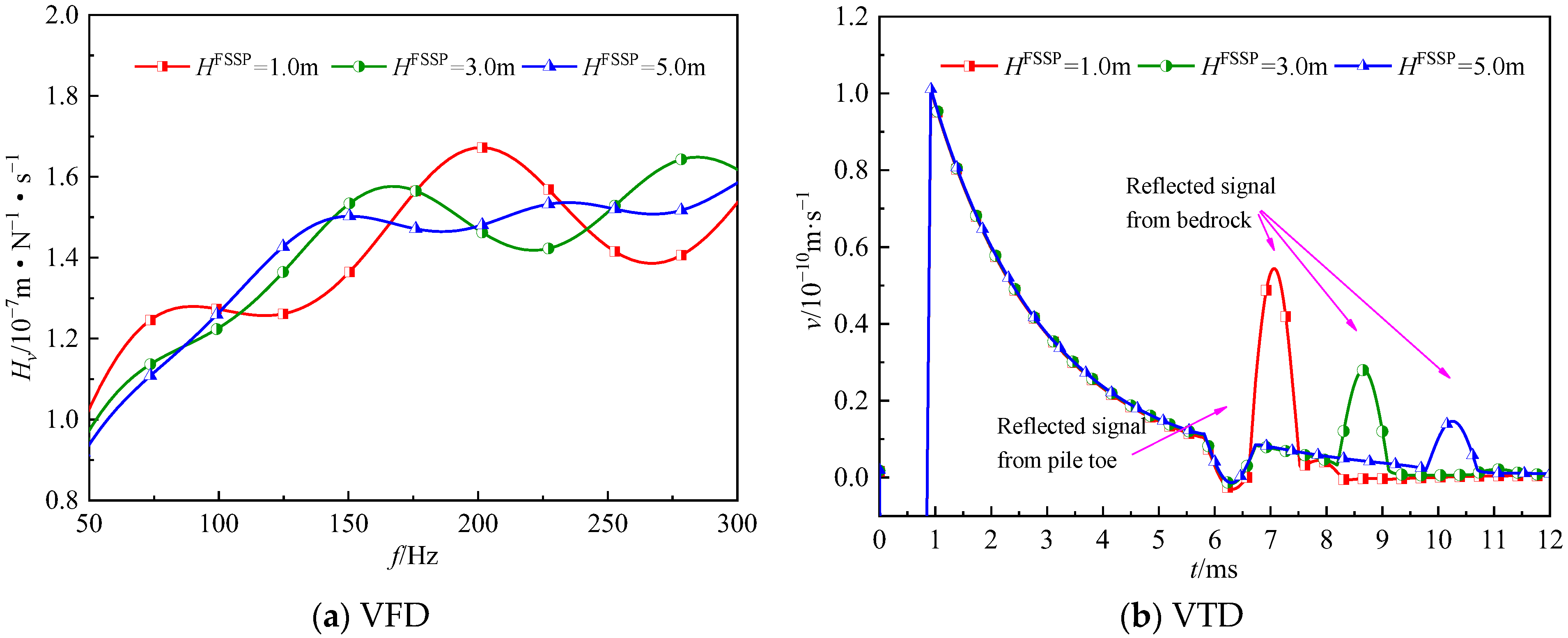
Figure 5 presents the influence of length of the FSSP on the vibration of the pile. As shown in Figure 5a, with increases in the length of the FSSP, the resonance amplitude and resonance frequency of the VFD both have an obvious decrease. Moreover, as the length of the FSSP increases, the RS from the pile remains basically unchanged, but the RS from the bedrock is delayed significantly and its amplitude also has an obvious decline.
In order to discuss the influence of the saturated interlayer on the vibration velocity, Layer 2 and Layer 6 are set as the interlayers of the saturated soils around and beneath pile, respectively, in the following analysis. The heterogeneity factors are defined as [23]:
ζ G 2 = G 2 / G j , j = 1 , 3
ζ G 6 = G 6 / G k , k = 4 , 5 , 7 , 8
If ζ G 2 = 1 or ζ G 6 = 1 , it is vertically homogeneous for the soil layers beneath or around pile, respectively; if ζ G 2 < 1 or ζ G 6 < 1 , the smaller the coefficient, the greater the attenuation; if ζ G 2 > 1 or ζ G 6 > 1 , the larger the coefficient, the greater the strengthening. ζ G 2 ( ζ G 6 ) is varied by only changing G2 (G6) and keeping Gj (Gk) constant.
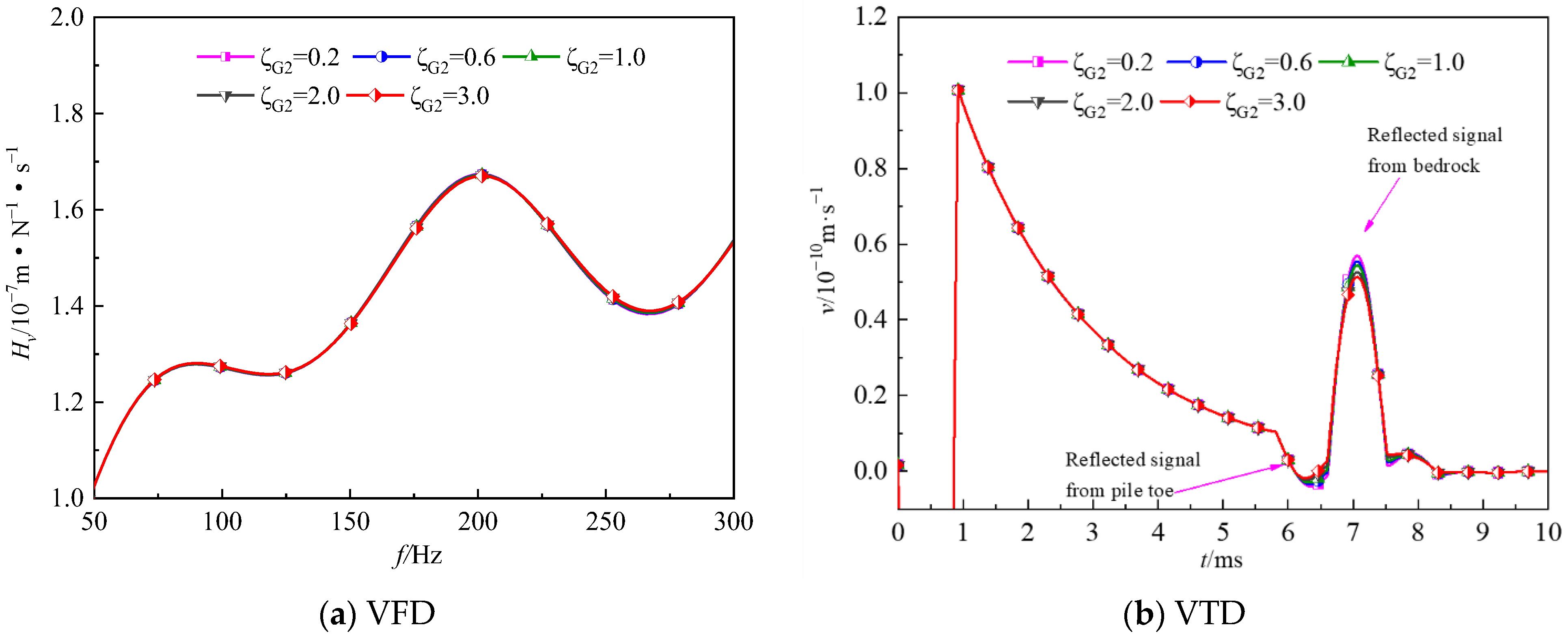
It is clear from Figure 6 that the influence of the interlayer of the saturated soils beneath the pile toe on both the VFD and VTD is negligible. In contrast, Figure 7 shows that both the VFD and reflected VTD clearly depend on the heterogeneity factor of the surrounding soils. Specifically, with the increase in the heterogeneity factor of the saturated surrounding soils, the amplitude of the VFD reduces. In addition, the vertical heterogeneity of the saturated surrounding soils can lead to an evident amplitude difference between neighboring crests in Figure 7a. With regard to the reflected velocity wave of the pile shaft shown in Figure 7b, there exist evident RSs due to the vertical heterogeneity of the saturated surrounding soils. When the vertical heterogeneity coefficient ζ G 6 < 1 , the RSs due to the vertical heterogeneity of the saturated surrounding soils oscillate in phase with the incident wave. Instead, when the vertical heterogeneity coefficient ζ G 6 > 1 , the RSs due to the vertical heterogeneity of the saturated surrounding soils oscillate in antiphase with the incident wave. The greater the vertical heterogeneity coefficient of the saturated surrounding soils, the less the oscillation amplitude of the RS from the bedrock.
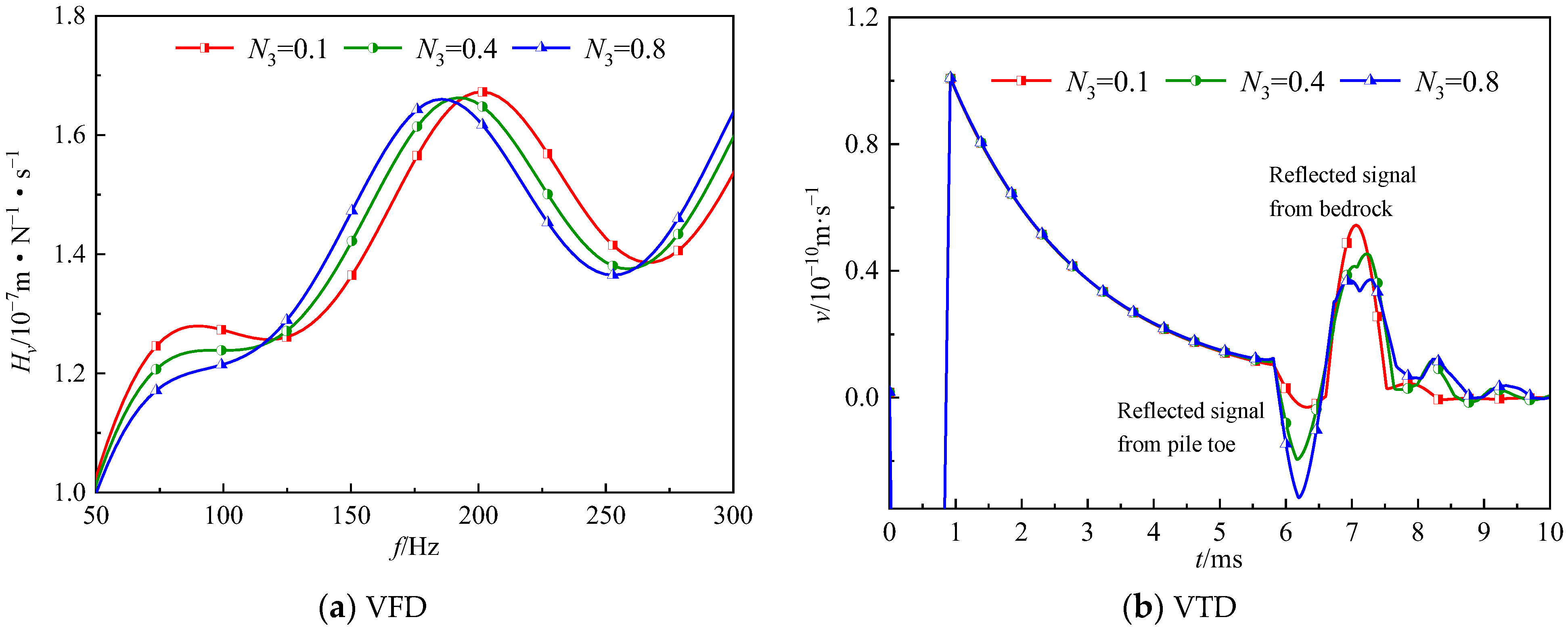
The effects of the porosity of the saturated soils around and beneath the pile on the vibration velocity are illustrated in Figure 8 and Figure 9, respectively. The porosity of the soils beneath the pile has an obvious effect on the resonance frequency of the VFD of the pile, while the porosity of the soils around the pile only influences the resonance amplitude of the VFD. Specifically, with the rise in the porosity of the soils around the pile, the resonance amplitude of the VFD increases gradually. In contrast, the resonance frequency of the VFD decreases with the rising porosity of the soils beneath the pile. With regard to the VTD, the RSs from the bedrock become greater with the rising porosity of the soils around the pile. In contrast, with the increasing porosity of the soils beneath the pile, the RS from the bedrock declines gradually, and that from the pile tip rises. Moreover, the porosity of the soils beneath the pile affects the RS from the pile tip to a greater extent than that of soils around pile.

5. Conclusions

Based on Biot’s theory, Novak’s plane-strain model and the FSSP model, an analytical methodology for the vibration of a friction pile in multilayered saturated media is proposed. The presented approach and relevant solution are validated by comparisons with existing solutions. Furthermore, numerical instances are used to investigate the influences of the porosity and heterogeneity of saturated soils on pile vibration. The results indicate that:
(1)
With the increase in the length of the FSSP, the resonance amplitude and resonance frequency of the velocity in the frequency domain both have an obvious decrease. Moreover, as the length of the FSSP increases, the RS from the pile remains basically unchanged, but the RS from the bedrock is delayed significantly and its amplitude also has an obvious decline.
(2)
Both the velocity admittance and reflected velocity wave clearly depend on the heterogeneity factor of the surrounding soil. In contrast, the influence of the heterogeneity factor of the pile end soil on the vertical vibration velocity of the pile can be ignored.
(3)
With the rising porosity of the soils around the pile, the RS from the bedrock becomes greater. In contrast, the RS from the bedrock declines and the RS from the pile increases when the porosity of the soils beneath the pile rises.
(4)
In terms of the proposed FSSP model, there exist two RSs from the pile tip and bedrockwithin the velocity in the time domain. In contrast, the RS from the bedrock cannot be identified in the solutions derived from the FSP model of single-phase media.
(5)
The developed methodology and corresponding solutions achieved with the FSSP model provide a theoretical reference for comprehensive understanding of the wave propagation of a friction pile embedded in heterogeneously saturated soil with limited thickness.
The importance of these original results for future studies:
(1)
The results related to the influence of the soil heterogeneity can be applied to evaluate the characteristics of layered soils by comparing the theoretical results with measured data.
(2)
The signal delay between the pile tip and bedrock can be used to guide the detection of the thickness of pile end soil in engineering practice.
The advantages of the proposed analytical methodology:
(1)
The proposed analytical methodology can consider the effect of the heterogeneity of the saturated pile around and beneath soils on the vibration of friction piles in saturated media, which was neglected in previous research.
(2)
The proposed analytical methodology provides a rigorous model for the dynamic interaction between piles and pile end saturated soils.

Author Contributions

Conceptualization, K.M.; methodology, K.M.; software, D.G.; validation, D.G.; formal analysis, D.G.; investigation, D.G.; resources, D.G.; data curation, K.M.; writing—original draft preparation, K.M.; writing—review and editing, K.M.; visualization, D.G.; supervision, K.M.; project administration, D.G.; funding acquisition, K.M. All authors have read and agreed to the published version of the manuscript.

Funding

This research was funded by the National Science Foundation for Young Scientists of China, grant number 52108326.

Institutional Review Board Statement

Not applicable.

Informed Consent Statement

Not applicable.

Data Availability Statement

Not applicable.

Conflicts of Interest

The authors declare no conflict of interest.

References

  1. Tsouvalas, A.; Metrikine, A.V. A semi-analytical model for the prediction of underwater noise from offshore pile driving. J. Sound Vib. 2013, 332, 3232–3257. [Google Scholar] [CrossRef]
  2. Yuan, B.X.; Li, Z.H.; Chen, W.J. Influence of Groundwater Depth on Pile–Soil Mechanical Properties and Fractal Characteristics under Cyclic Loading. Fractal Fract. 2022, 6, 198. [Google Scholar] [CrossRef]
  3. Luan, L.B.; Zheng, C.J.; Kouretzis, G.P. Dynamic analysis of pile groups subjected to horizontal loads considering coupled pile-to-pile interaction. Comput. Geotech. 2020, 117, 103276. [Google Scholar] [CrossRef]
  4. Yuan, B.X.; Sun, M.; Xiong, L. Investigation of 3D deformation of transparent soil around a laterally loaded pile based on a hydraulic gradient model test. J. Build. Eng. 2020, 28, 101024. [Google Scholar] [CrossRef]
  5. Liang, F.Y.; Zhao, M.Y.; Qin, C.R. Centrifugal test of a road embankment built after new dredger fill on thick marine clay. Mar. Georesources Geotechnol. 2020, 38, 114–121. [Google Scholar] [CrossRef]
  6. Song, H.; Pei, H.F.; Xu, D.; Cui, C. Performance study of energy piles in different climatic conditions by using multi-sensor technologies. Measurement 2020, 162, 107875. [Google Scholar] [CrossRef]
  7. Dobry, R.; Gazetas, G. Simple method for dynamic stiffness and damping of floating pile groups. Geotechnique 1988, 38, 557–574. [Google Scholar] [CrossRef]
  8. Wang, K.H.; Wu, W.B.; Zhang, Z.Q.; Leo, C.J. Vertical dynamic response of an inhomogeneous viscoelastic pile. Comput. Geotech. 2010, 37, 536–544. [Google Scholar] [CrossRef]
  9. Shadlou, M.; Bhattacharya, S. Dynamic stiffness of pile in a layered continuum. Géotechnique 2014, 64, 303–319. [Google Scholar] [CrossRef]
  10. Nogami, T.; Konagai, K. Dynamic Response of Vertically Loaded Nonlinear Pile Foundations. J. Geotech. Eng. 1987, 113, 147–160. [Google Scholar] [CrossRef]
  11. Han, Y.; Vaziri, H. Dynamic response of pile groups under lateral loading. Soil. Dyn. Earthq. Eng. 1992, 11, 87–99. [Google Scholar] [CrossRef]
  12. Anoyatis, G.; Mylonakis, G. Dynamic Winkler modulus for axially loaded piles. Geotechnique 2012, 62, 521–536. [Google Scholar] [CrossRef] [Green Version]
  13. Novak, M. Dynamic Stiffness and Damping of Piles. Can. Geotech. J. 1974, 11, 574–598. [Google Scholar] [CrossRef]
  14. Nogami, T.; Novák, M. Soil-pile interaction in vertical vibration. Earthq. Eng. Struct. D 1976, 4, 277–293. [Google Scholar] [CrossRef]
  15. Wu, W.B.; Wang, K.H.; Zhang, Z.Q.; Leo, C.J. Soil-pile interaction in the pile vertical vibration considering true three-dimensional wave effect of soil. Int. J. Numer. Anal. Methods Geomech. 2013, 37, 2860–2876. [Google Scholar] [CrossRef]
  16. West, R.; Heelis, M.; Pavlović, M. Stability of end-bearing piles in a non-homogeneous elastic foundation. Int. J. Numer. Anal. Methods Geomech. 1997, 21, 845–861. [Google Scholar] [CrossRef]
  17. Ding, X.M.; Liu, H.L.; Chu, J.; Cheng, K. Time-domain solution for transient dynamic response of a large-diameter thin-walled pipe pile. Earthq. Eng. Eng. Vib. 2015, 14, 239–251. [Google Scholar] [CrossRef]
  18. Gao, L.; Wang, K.H.; Xiao, S.; Li, Z.Y.; Wu, J.T. An analytical solution for excited pile vibrations with variable section impedance in the time domain and its engineering application. Comput. Geotech. 2016, 73, 170–178. [Google Scholar] [CrossRef]
  19. Meng, K.; Su, H. Analytical model of large-diameter viscoelastic floating pile and application in pile low-strain integrity testing. Soil Dyn. Earthq. Eng. 2022, 158, 107296. [Google Scholar] [CrossRef]
  20. Tsouvalas, A.; Metrikine, A.V. A three-dimensional vibroacoustic model for the prediction of underwater noise from offshore pile driving. J. Sound Vib. 2014, 333, 2283–2311. [Google Scholar] [CrossRef]
  21. Muki, R.; Sternberg, E. Elastostatic load-transfer to a half-space from a partially embedded axially loaded rod. Int. J. Solids Struct. 1970, 6, 69–90. [Google Scholar] [CrossRef]
  22. Wu, W.B.; Huang, S.; Ma, S.; Xu, X. A New Model for the Dynamic Interaction of a Pile and Pile End Soil. In Proceedings of the International Conference on Pipelines and Trenchless, Xiamen, China, 13–15 November 2014; pp. 561–570. [Google Scholar] [CrossRef]
  23. Nogami, T. Dynamic group effect in axial responses of grouped piles. J. Geotech. Eng. 1983, 109, 228–243. [Google Scholar] [CrossRef]
  24. Wang, N.; Wang, K.H.; Wu, W.B. Analytical model of vertical vibrations in piles for different tip boundary conditions: Parametric study and applicationsx. J. Zhejiang Univ. Sci. A 2013, 14, 79–93. [Google Scholar] [CrossRef] [Green Version]
  25. Lü, S.H.; Wang, K.H.; Wu, W.B.; Leo, C.J. Vertical vibration of pile in layered soil based on Rayleigh-Love rod theory and fictitious soil-pile model. J. Cent. South Univ. 2015, 22, 1909–1918. [Google Scholar] [CrossRef]
  26. Nogami, T.; Ren, F.; Chen, J.W.; Mason, A.B. Vertical Vibration of Pile in Vibration-Induced Excess Pore Pressure Field. J. Geotech. Geoenviron. Eng. 1997, 123, 422–429. [Google Scholar] [CrossRef]
  27. Xu, D.S.; Huang, M.; Zhou, Y. One-dimensional compression behavior of calcareous sand and marine clay mixtures. Int. J. Geomech. 2020, 20, 04020137. [Google Scholar] [CrossRef]
  28. Cai, Y.Q.; Hu, X.Q.; Xu, C.J. Vertical dynamic response of a rigid foundation embedded in a poroelastic soil layer. Int. J. Numer. Anal. Met. 2009, 33, 1363–1388. [Google Scholar] [CrossRef]
  29. Senjuntichai, T.; Rajapakse, R.K.N.D. Transient response of a circular cavity in a poroelastic medium. Int. J. Numer. Anal. Met. 1993, 17, 357–383. [Google Scholar] [CrossRef]
  30. Hasheminejad, S.M.; Hosseini, H. Dynamic stress concentration near a fluid-filled permeable borehole induced by general modal vibrations of an internal cylindrical radiator. Soil. Dyn. Earthq. Eng. 2002, 22, 441–458. [Google Scholar] [CrossRef]
  31. Li, Q.; Wang, K.H.; Xie, K.H. Dynamic response of vertically vibrating pile during freezing and thawing. Chin. J. Mech. Eng. 2006, 8, 48–55. [Google Scholar]
  32. Liu, H.L.; Zheng, C.J.; Ding, X.M. Vertical dynamic response of a pipe pile in saturated soil layer. Geomech. Eng. 2014, 61, 57–66. [Google Scholar] [CrossRef]
  33. Zheng, C.J.; Kouretzis, G.P.; Sloan, S.W.; Liu, H.; Ding, X. Vertical vibration of an elastic pile embedded in poroelastic soil. Soil Dyn. Earthq. Eng. 2015, 77, 177–181. [Google Scholar] [CrossRef]
  34. Zeng, X.; Rajapakse, R.K.N.D. Dynamic Axial Load Transfer from Elastic Bar to Poroelastic Medium. J. Eng. Mech. 1999, 125, 1048–1055. [Google Scholar] [CrossRef]
  35. Militano, G.; Rajapakse, R.K.N.D. Dynamic response of a pile in a multi-layered soil transient torsional and axial loading. Géotechnique 1999, 49, 91–109. [Google Scholar] [CrossRef]
  36. Peng, L.; Song, E.X. A viscous-spring transmitting boundary for cylindrical wave propagation in saturated poroelastic media. Soil Dyn. Earthq. Eng. 2014, 65, 269–283. [Google Scholar] [CrossRef]
  37. Wu, W.B.; Wang, K.H.; Ma, S.J. Vertical dynamic response of pile in layered soil based on virtual soil pile model. J. Cent. South Univ. 2012, 19, 1999–2007. [Google Scholar] [CrossRef]
Figure 1. Coupled vibration of a pile–soil system.
Jmse 10 01886 g001
Figure 2. Expression for harmonic pressure.
Jmse 10 01886 g002
Figure 3. Comparison of the reduced form of DI with the DI derived by Wu et al. [15].
Jmse 10 01886 g003
Figure 4. Comparison between the proposed and existing solutions [31,37].
Jmse 10 01886 g004
Figure 5. Influence of the length of the FSSP on the vibration velocity of the pile.
Jmse 10 01886 g005
Figure 6. Influence of the vertical heterogeneity of pile end soils on the vertical vibration velocity.
Jmse 10 01886 g006
Figure 7. Influence of the vertical heterogeneity of surrounding soils on the vertical vibration velocity.
Jmse 10 01886 g007
Figure 8. Effect of the porosity of the saturated soils around the pile on pile vertical vibration.
Jmse 10 01886 g008
Figure 9. Effect of the porosity of the pile end soils on pile vertical vibration velocity.
Jmse 10 01886 g009
Table 1. Parameters of the soil layers.
Soil LayersSaturated Soils Beneath PileSaturated Soils around Pile
12345678
Depth/m10.610.31086420
Thickness/m0.40.30.322222
Publisher’s Note: MDPI stays neutral with regard to jurisdictional claims in published maps and institutional affiliations.