

Assessment of the Roll Derivatives of Different Surface Ships Based on Numerical Pure Roll Simulation


Abstract
1. Introduction
2. Test Overview
2.1. Coordinate System
2.2. Pure Roll Simulation
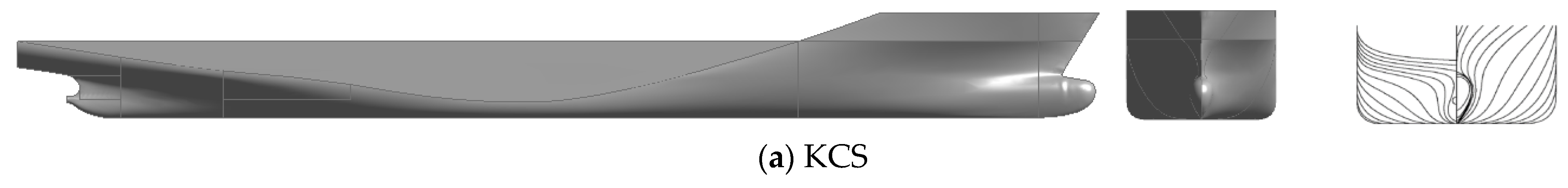
2.3. Ship Models
3. Numerical Model
3.1. Governing Equation
3.2. CFD Simulation
3.3. Numerical Uncertainty Analysis
- (i)
- Monotonic convergence (MC): 0 < < 1;
- (ii)
- Oscillatory convergence (OC): < 0;
- (iii)
- Divergence (Div): > 1.
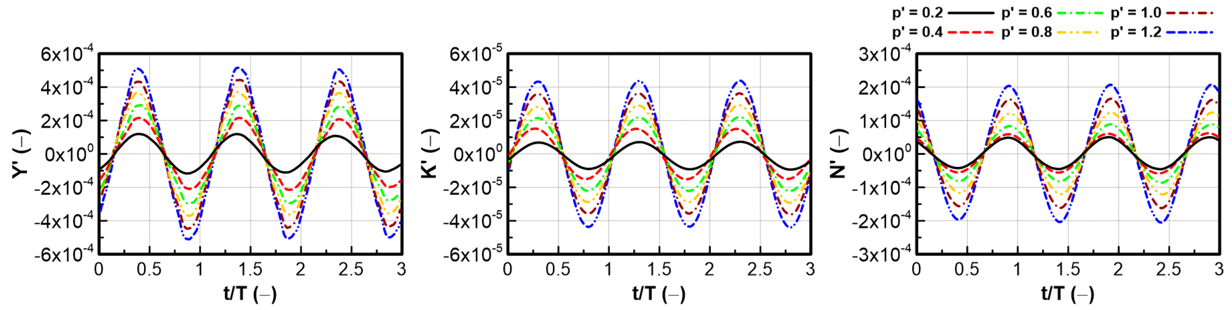
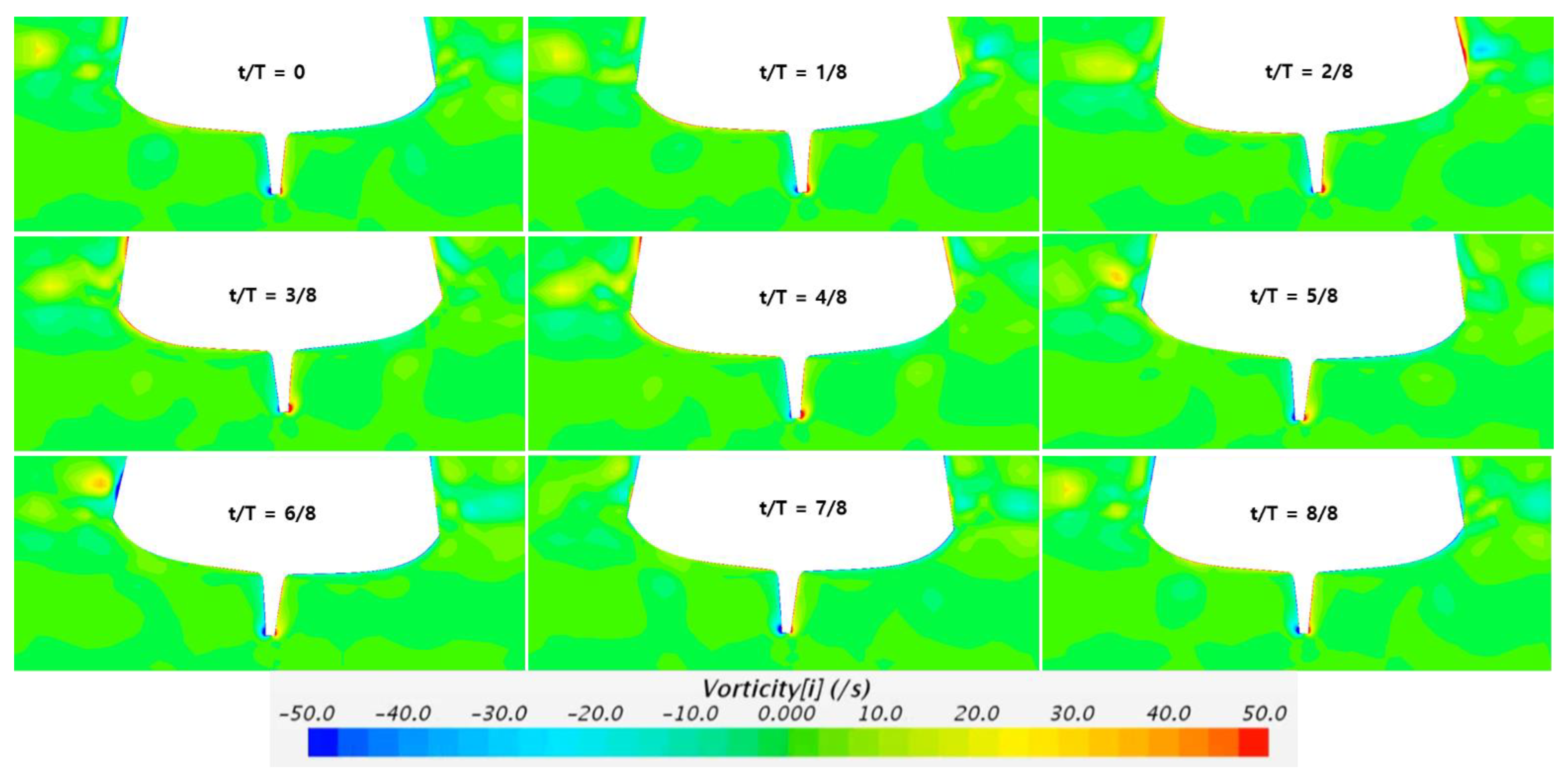
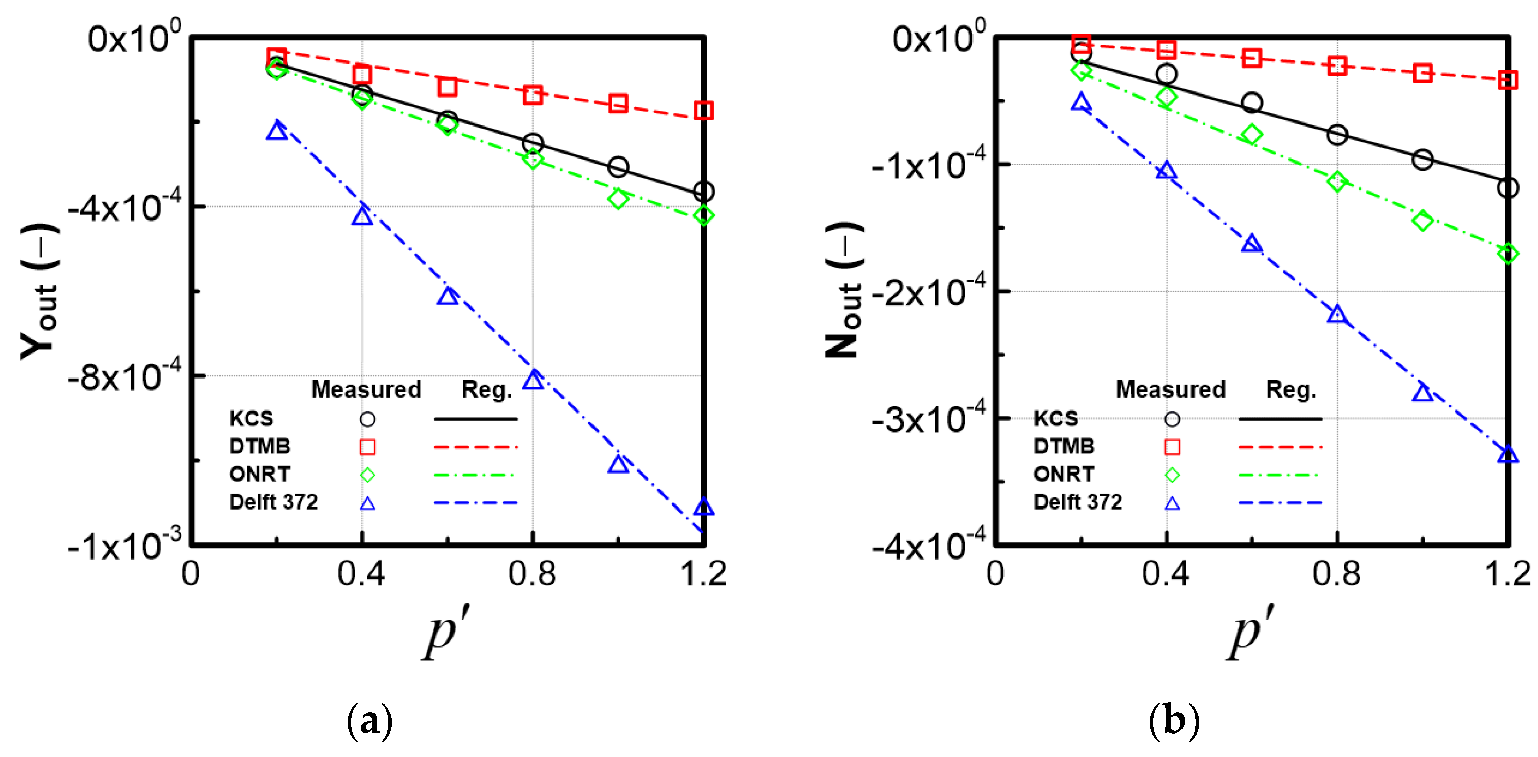
4. Results and Discussion
5. Conclusions
Author Contributions
Funding
Institutional Review Board Statement
Informed Consent Statement
Data Availability Statement
Conflicts of Interest
Nomenclature
| Symbol | Unit | Description |
| B | m | Breadth of ship |
| - | Froude number | |
| m | Transverse metacentric height | |
| K | Nm | Roll moment |
| KG | m | Height center of gravity above keel |
| m | Ship length between perpendiculars | |
| N | Nm | Yaw moment |
| rad/s | Roll rate | |
| rad/s2 | Roll acceleration | |
| - | Nondimensionless roll rate | |
| rad/s | Yaw rate | |
| m | Draft | |
| m/s | Ship speed | |
| m/s | Surge velocity | |
| m/s | Sway velocity | |
| m/s | Heave velocity | |
| X | N | Surge force |
| Y | N | Sway force |
| Z | N | Heave force |
| deg. | Drift angle | |
| kg/m3 | Water density | |
| deg. | Roll angle | |
| deg. | Heading angle | |
| rad/s | Frequency | |
| kgf | Displacement weight |
References
- Hajivand, A.; Mousavizadegan, H. Virtual simulation of maneuvering captive tests for a surface vessel. Int. J. Nav. Archit. Ocean Eng. 2015, 7, 848–872. [Google Scholar] [CrossRef]
- Liu, Y.; Zou, L.; Zou, Z.; Guo, H. Prediction of ship maneuverability based on virtual captive model tests. Eng. Appl. Comput. Fluid Mech. 2018, 12, 334–353. [Google Scholar] [CrossRef]
- Framceschi, A.; Piaggio, B.; Tonelli, R.; Villa, D.; Viviani, M. Assessment of the maneuverability characteristics of a twin shaft naval vessel using an open-source CFD code. J. Mar. Sci. Eng. 2021, 9, 665. [Google Scholar] [CrossRef]
- Li, S.; Liu, C.; Chu, X.; Zheng, M.; Wang, Z.; Kan, J. Ship maneuverability modeling and numerical prediction using CFD with body force propeller. Ocean Eng. 2022, 264, 112454. [Google Scholar] [CrossRef]
- Kim, Y.G.; Yeo, D.J.; Son, N.S.; Kim, S.Y.; Yun, K.H.; Oh, B.I. Prediction of Maneuverability of KCS with 4 Degrees of Freedom. J. Soc. Nav. Archit. Korea 2011, 48, 267–274. [Google Scholar] [CrossRef]
- Yoshimura, Y. Effect of Roll Motion on Ship Manoeuvrability by a Rudder to Yaw Response Equation. J. Jpn. Soc. Nav. Archit. Ocean Eng. 2011, 13, 11–18. [Google Scholar] [CrossRef][Green Version]
- Yasukawa, H.; Yoshimura, Y. Roll-coupling effect on ship maneuverability. Ship Technol. Res. 2014, 21, 16–32. [Google Scholar] [CrossRef]
- Fukui, Y.; Yokota, H.; Yano, H.; Kondo, M.; Nakano, T.; Yoshimura, Y. 4-DOF Mathematical Model for Manoeuvering Simulation including Roll Motion. J. Jpn. Soc. Nav. Archit. Ocean Eng. 2016, 24, 167–179. [Google Scholar] [CrossRef][Green Version]
- Yasukawa, H.; Sakuno, R.; Yoshimura, Y. Practical maneuvering simulation method of ships considering the roll-coupling effect. J. Mar. Sci. Technol. 2019, 24, 1280–1296. [Google Scholar] [CrossRef]
- Kim, D.H.; Baek, H.M.; Lee, S.K.; Kim, E.S. Development of Apparatus for Pure Roll-Motion Test of Underwater Vehicles. J. Navig. Port Res. 2021, 45, 16–25. [Google Scholar]
- Park, J.Y.; Kim, N.; Rhee, K.P.; Yoon, H.K.; Kim, C.; Jung, C.; Ahn, K.; Lee, S. Study on Coning Motion Test for Submerged Body. J. Ocean Eng. Technol. 2015, 29, 436–444. [Google Scholar] [CrossRef]
- Yoon, H.K.; Son, N.S. Estimation of Roll Related Coeficients of a Ship by Using the System Identification Method. J. Soc. Nav. Archit. Korea 2004, 41, 53–58. [Google Scholar]
- Yoon, H.K.; Son, N.S.; Lee, G.J. Estimation of the Roll Hydrodynamic Moment Model of a Ship by Using the System Identificaiton Method and the Free Runing Model Test. IEEE J. Ocean. Eng. 2007, 32, 798–806. [Google Scholar] [CrossRef]
- Jeon, M.; Yoon, H.K.; Park, J.; Rhee, S.H.; Seo, J. Identification of 4-DoF Maneuvering Mathematical Models for a Combatant in Intact and Damaged Condition. Int. J. Nav. Archit. Ocean Eng. 2022, 14, 100480. [Google Scholar] [CrossRef]
- Bekhit, A.; Popescu, F. URANSE-Based Numerical Prediction for the Free Roll Decay of the DTMB Ship Model. J. Mar. Sci. Eng. 2021, 9, 452. [Google Scholar] [CrossRef]
- Gokce, M.K.; Kinaci, O.K. Numerical simulations of free roll decay of DTMB 5415. Ocean Eng. 2018, 159, 539–551. [Google Scholar] [CrossRef]
- Sadat-Hosseini, H.; Carrica, P.; Stern, F.; Umeda, N.; Hashimoto, H.; Yamamura, S.; Mastuda, A. CFD, system-based and EFD study of ship dynamic instability events: Surf-riding periodic motion, and broaching. Ocean Eng. 2011, 38, 88–110. [Google Scholar] [CrossRef]
- Araki, M.; Sadat-Hosseini, H.; Sanada, Y.; Tanimoto, K.; Umeda, N.; Stern, F. Estimating maneuvering coefficients using system identification methods with experimental, system-based, and CFD free-runing trial data. Ocean Eng. 2012, 51, 63–84. [Google Scholar] [CrossRef]
- Sanada, Y.; Tanimoto, K.; Takagi, K.; Gui, L.; Toda, Y.; Stern, F. Trajectories for ONR Tumblehome maneuvering in calm water and waves. Ocean Eng. 2013, 72, 45–65. [Google Scholar] [CrossRef]
- Veer, V. Experimental Results of Motions, Hydrodynamic Coefficients and Wave Loads on the 372 Catamaran Model; Report 1129; Delft University of Technology: Delft, The Netherlands, 1998. [Google Scholar]
- ITTC. Practical Guidelines for Ship CFD Application. In Proceedings of the 26th International Towing Tanks Conference, Rio de Janeiro, Brazil, 28 August–3 September 2011; Number 7.5-03-02-03; ITTC: 2011. Available online: https://ittc.info/media/1357/75-03-02-03.pdf (accessed on 17 October 2022).
- ITTC. Uncertainty Analysis in CFD Verification and Validation Methodology and Procedures. In Proceedings of the 29th International Towing Tanks Conference, Virtual, 13–18 June 2021; 7.5-03-01-01; ITTC: 2021. Available online: https://www.ittc.info/media/9765/75-03-01-01.pdf (accessed on 17 October 2022).
- Roache, P.J. Verification and Validation in Computational Science and Engineering; Hermosa: Albuquerque, NM, USA, 1998. [Google Scholar]


| Item (Unit) | KCS | DTMB | ONRT | Delft 372 Cat. |
|---|---|---|---|---|
| Scale ratio | 1/52.667 | 1/35.480 | 1/48.935 | 1/27.571 |
| Lpp (m) | 4.367 | 4.002 | 3.147 | 3.627 |
| B (m) | 0.611 | 0.537 | 0.384 | 1.137 |
| T (m) | 0.205 | 0.173 | 0.112 | 0.181 |
| Δ (kgf) | 365.0 | 193.3 | 72.6 | 154.0 |
| KG (m) | 0.138 | 0.213 | 0.162 | 0.411 |
| GMT (m) | 0.011 | 0.055 | 0.042 | 1.791 |
| U (m/s) | 1.701 | 2.588 | 1.111 | 2.685 |
| Fn (-) | 0.260 | 0.413 | 0.200 | 0.450 |
| Motion Variable | KCS | DTMB | ONRT | Delft 372 Cat. |
|---|---|---|---|---|
| Speed (m/s) | 1.701 | 2.588 | 1.111 | 2.685 |
| p′ (-) | 0.2, 0.4, 0.6, 0.8, 1.0, 1.2 | |||
| (°) | 0.5, 1.0, 1.5, 2.0, 2.5, 3.0 | |||
| Mesh Convergence | Yin | Yout | Kin | Kout | Nin | Nout |
|---|---|---|---|---|---|---|
| Solution | 3.17 × 10⁻⁴ | −4.35 × 10⁻⁴ | 4.13 × 10⁻⁵ | −1.24 × 10⁻⁵ | −9.93 × 10⁻⁵ | 1.61 × 10⁻⁴ |
| Solution | 3.04 × 10⁻⁴ | −4.27 × 10⁻⁴ | 4.20 × 10⁻⁵ | −1.19 × 10⁻⁵ | −1.01 × 10⁻⁴ | 1.72 × 10⁻⁴ |
| Solution | 2.78 × 10⁻⁴ | −4.10 × 10⁻⁴ | 4.30 × 10⁻⁵ | −1.07 × 10⁻⁵ | −9.84 × 10⁻⁵ | 1.67 × 10⁻⁴ |
| Convergence ratio () | 0.47 | 0.45 | 0.72 | 0.41 | −0.64 | −2.47 |
| Convergence tendency | MC | MC | MC | MC | OC | OC |
| 2.16 | 2.31 | 0.96 | 2.21 | 1.30 | 2.60 | |
| () | 1.29 | 1.53 | 0.20 | 0.96 | 2.52 | 2.36 |
| Oscillatory uncertainty () | - | - | - | - | 1.26 | 3.6 |
| CF-based uncertainty () | 1.41 | 0.78 | 0.23 | 1.48 | - | - |
| SF-based uncertainty () | 1.38 | 0.91 | 0.18 | 1.00 | 2.84 | 4.02 |
| Mesh Convergence | Yin | Yout | Kin | Kout | Nin | Nout |
|---|---|---|---|---|---|---|
| Solution | 3.09 × 10⁻⁴ | −4.2 × 10⁻⁴ | 3.70 × 10⁻⁵ | −1.13 × 10⁻⁵ | −1.06 × 10⁻⁴ | 1.76 × 10⁻⁴ |
| Solution | 3.04 × 10⁻⁴ | −4.27 × 10⁻⁴ | 4.20 × 10⁻⁵ | −1.19 × 10⁻⁵ | −1.01 × 10⁻⁴ | 1.72 × 10⁻⁴ |
| Solution | 3.15 × 10⁻⁴ | −4.32 × 10⁻⁴ | 3.88 × 10⁻⁵ | −1.31 × 10⁻⁵ | −1.10 × 10⁻⁴ | 1.67 × 10⁻⁴ |
| Convergence ratio () | −0.44 | 0.81 | −1.57 | 0.51 | −0.58 | 0.80 |
| Convergence tendency | OC | MC | OC | MC | OC | MC |
| 2.35 | 0.61 | 1.30 | 1.93 | 1.59 | 0.63 | |
| () | 3.05 | 3.24 | 3.94 | 2.93 | 1.87 | 1.34 |
| Oscillatory uncertainty () | 2.35 | - | 2.50 | - | 2.60 | - |
| CF-based uncertainty () | - | 2.33 | - | 1.94 | - | 1.56 |
| SF-based uncertainty () | 1.84 | 4.45 | 2.43 | 1.56 | 2.64 | 1.94 |
| HD Derivatives | KCS | DTMB | ONRT | Delft 372 |
|---|---|---|---|---|
| −7.53 × 10⁻⁵ | −1.44 × 10⁻⁵ | −9.83 × 10⁻⁵ | −3.22 × 10⁻⁵ | |
| −1.03 × 10⁻⁵ | −2.22 × 10⁻⁶ | −2.34 × 10⁻⁵ | −4.82 × 10⁻⁵ | |
| 2.62 × 10⁻⁵ | 1.75 × 10⁻⁵ | 6.05 × 10⁻⁵ | 1.80 × 10⁻⁵ | |
| −9.22 × 10⁻⁴ | −2.81 × 10⁻⁴ | −7.19 × 10⁻⁴ | −1.46 × 10⁻³ | |
| −2.64 × 10⁻⁵ | −4.30 × 10⁻⁵ | −1.41 × 10⁻⁴ | −6.75 × 10⁻⁴ | |
| 3.21 × 10⁻⁴ | 4.47 × 10⁻⁵ | 3.43 × 10⁻⁴ | 3.43 × 10⁻⁴ |
Publisher’s Note: MDPI stays neutral with regard to jurisdictional claims in published maps and institutional affiliations. |
© 2022 by the authors. Licensee MDPI, Basel, Switzerland. This article is an open access article distributed under the terms and conditions of the Creative Commons Attribution (CC BY) license (https://creativecommons.org/licenses/by/4.0/).
Share and Cite
Mai, T.L.; Vo, A.K.; Yoon, H.K.; Park, D.K. Assessment of the Roll Derivatives of Different Surface Ships Based on Numerical Pure Roll Simulation. J. Mar. Sci. Eng. 2022, 10, 1702. https://doi.org/10.3390/jmse10111702
Mai TL, Vo AK, Yoon HK, Park DK. Assessment of the Roll Derivatives of Different Surface Ships Based on Numerical Pure Roll Simulation. Journal of Marine Science and Engineering. 2022; 10(11):1702. https://doi.org/10.3390/jmse10111702
Chicago/Turabian StyleMai, Thi Loan, Anh Khoa Vo, Hyeon Kyu Yoon, and Dong Kyou Park. 2022. "Assessment of the Roll Derivatives of Different Surface Ships Based on Numerical Pure Roll Simulation" Journal of Marine Science and Engineering 10, no. 11: 1702. https://doi.org/10.3390/jmse10111702
APA StyleMai, T. L., Vo, A. K., Yoon, H. K., & Park, D. K. (2022). Assessment of the Roll Derivatives of Different Surface Ships Based on Numerical Pure Roll Simulation. Journal of Marine Science and Engineering, 10(11), 1702. https://doi.org/10.3390/jmse10111702