


The Impact of Scour on Laterally Loaded Piles Bored and Socketed in Marine Clay


Abstract
1. Introduction
2. Materials and Methods
2.1. Validation with Field Lateral Load Tests
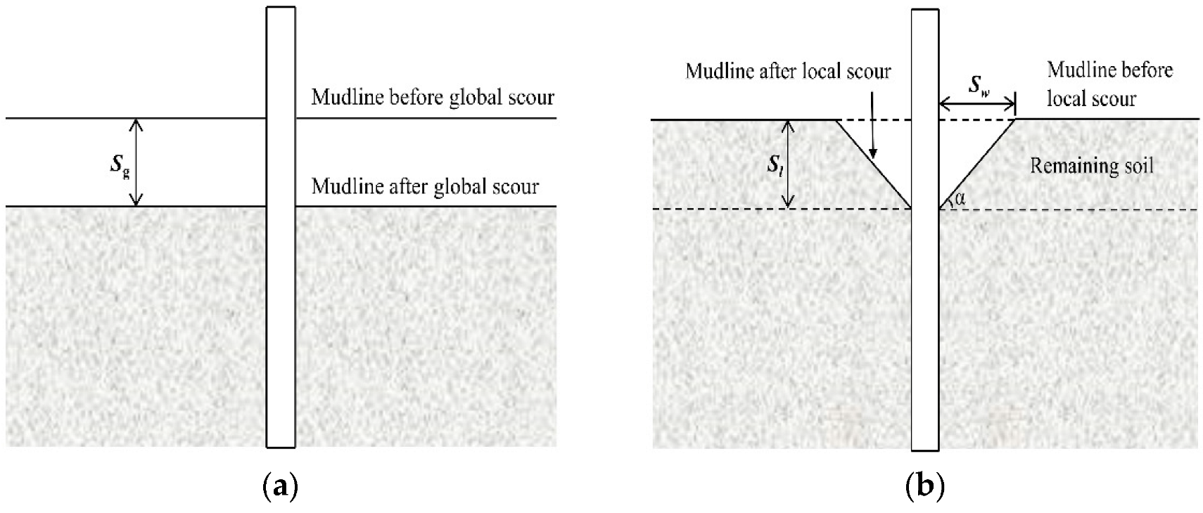
2.2. Mechanics of Scour
3. Results and Discussion
3.1. Lateral Load Capacity
3.2. Effect of Global Scour
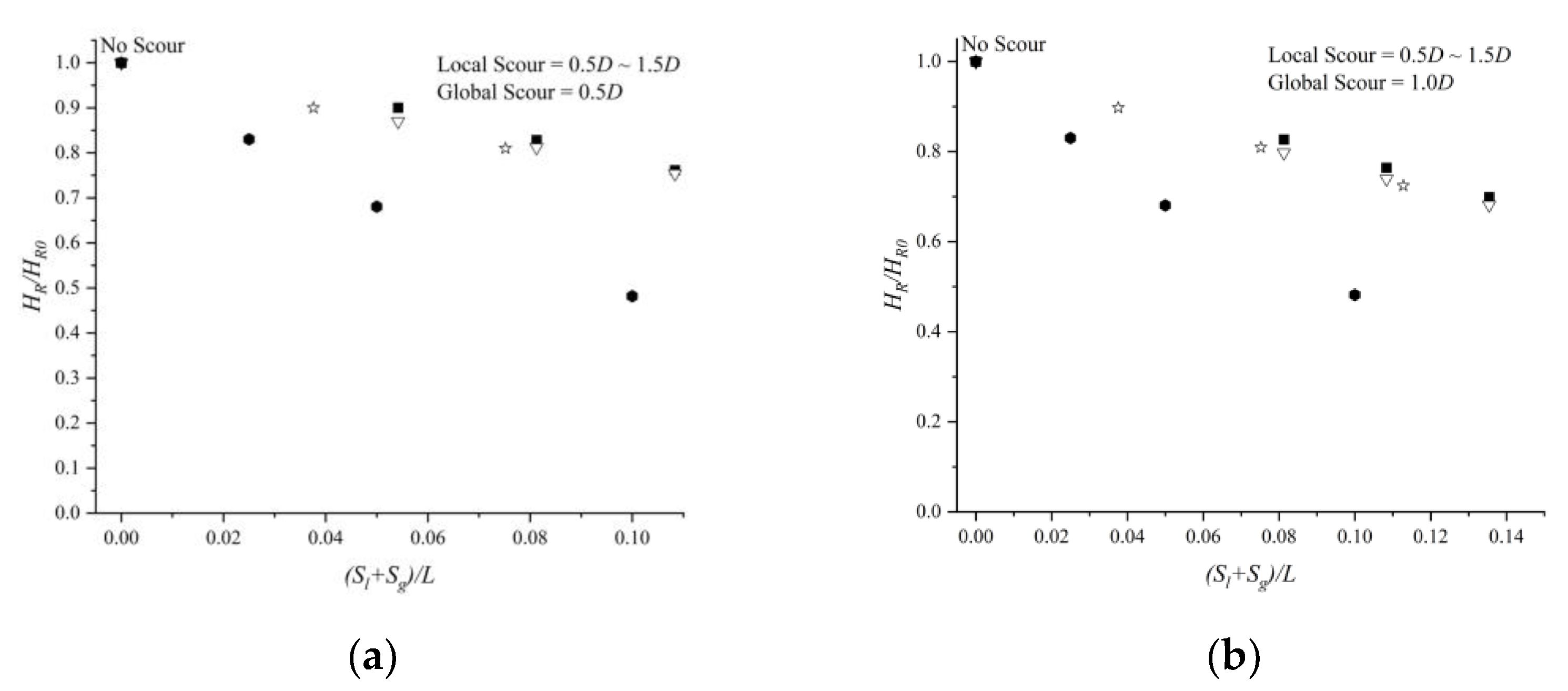
3.3. Effect of Local Scour
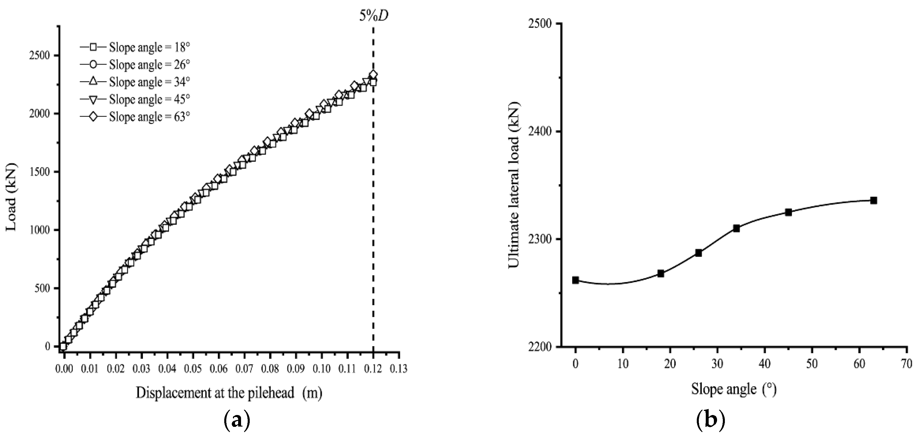
3.3.1. Effect of Slope Angle α
3.3.2. Effect of Slope Width Sw
3.3.3. Effect of Local Scour Depth Sl
3.4. Effect of Scour on Bending Moment
3.5. A SemiEmpirical Formula for Lateral Load Capacity
3.6. Validation Formula
4. Conclusions
Author Contributions
Funding
Institutional Review Board Statement
Informed Consent Statement
Data Availability Statement
Conflicts of Interest
References
- McConnell, J.R.; Cann, M. Assessment of Bridge Strength and Stability under Scour Conditions. In Proceedings of the ASCE SEI 2010 Structures Congress, Orlando, FL, USA, 12–15 May 2010; pp. 121–132. [Google Scholar] [CrossRef]
- Lin, C.; Bennett, C.; Han, J.; Parsons, R.L. Integrated analysis of the performance of pile-supported bridges under scoured conditions. Eng. Struct. 2011, 36, 27–38. [Google Scholar] [CrossRef]
- Lagasse, P. Countermeasures to Protect Bridge Piers from Scour, 1st ed.; Transportation Research Board: Washington, DC, USA, 2007. [Google Scholar]
- Li, Q.; Prendergast, L.J.; Askarinejad, A.; Chortis, G.; Gavin, K. Centrifuge Modeling of the Impact of Local and Global Scour Erosion on the Monotonic Lateral Response of a Monopile in Sand. Geotech. Test. J. 2020, 43, 1084–1100. [Google Scholar] [CrossRef]
- Guan, D.; Chiew, Y.-M.; Melville, B.W.; Zheng, J. Current-induced scour at monopile foundations subjected to lateral vibrations. Coast. Eng. 2019, 144, 15–21. [Google Scholar] [CrossRef]
- Tang, H.-W.; Ding, B.; Chiew, Y.-M.; Fang, S.-L. Protection of bridge piers against scouring with tetrahedral frames. Int. J. Sediment Res. 2009, 24, 385–399. [Google Scholar] [CrossRef]
- Wang, H.; Tang, H.; Liu, Q.; Wang, Y. Local Scouring around Twin Bridge Piers in Open-Channel Flows. J. Hydraul. Eng. 2016, 142, 06016008. [Google Scholar] [CrossRef]
- Melville, B.W.; Raudkivi, A.J. Flow characteristics in local scour at bridge piers. J. Hydraul. Res. 1977, 15, 373–380. [Google Scholar] [CrossRef]
- Xiao, Y.; Jia, H.; Guan, D.; Liang, D.; Yuan, S.; Tang, H. Experimental investigation on scour topography around high-rise structure foundations. Int. J. Sediment Res. 2020, 36, 348–361. [Google Scholar] [CrossRef]
- Melville, B.W.; Chiew, Y.-M. Time Scale for Local Scour at Bridge Piers. J. Hydraul. Eng. 1999, 125, 59–65. [Google Scholar] [CrossRef]
- Liang, D.-F.; Jia, H.; Xiao, Y.; Yuan, S.-Y. Experimental investigation of turbulent flows around high-rise structure foundations and implications on scour. Water Sci. Eng. 2021, 15, 47–56. [Google Scholar] [CrossRef]
- Wang, C.; Yu, X.; Liang, F. A review of bridge scour: Mechanism, estimation, monitoring and countermeasures. Nat. Hazards 2017, 87, 1881–1906. [Google Scholar] [CrossRef]
- Matlock, H. Correlation for Design of Laterally Loaded Piles in Soft Clay. In Proceedings of the 2nd Offshore Technology Conference, Houston, TX, USA, 22–24 April 1970; pp. 577–594. [Google Scholar] [CrossRef]
- Lee, P.; Gilbert, L. Behavior Of Laterally Loaded Pile In Very Soft Clay. In Proceedings of the Offshore Technology Conference, Houston, TX, USA, 30 April 1979; Volume 3401, pp. 387–392. [Google Scholar] [CrossRef]
- Duncan, J.M.; Evans, L.T.; Ooi, P.S.K. Lateral Load Analysis of Single Piles and Drilled Shafts. J. Geotech. Eng. 1994, 120, 1018–1033. [Google Scholar] [CrossRef]
- White, D.J.; Thompson, M.J.; Suleiman, M.T.; Schaefer, V.R. Behavior of Slender Piles Subject to Free-Field Lateral Soil Movement. J. Geotech. Geoenviron. Eng. 2008, 134, 428–436. [Google Scholar] [CrossRef]
- Matlock, H.; Reese, L.C. Generalized Solutions for Laterally Loaded Piles. Trans. Am. Soc. Civ. Eng. 1962, 127, 1220–1248. [Google Scholar] [CrossRef]
- Reese, L.; Wang, S.; Long, J. Scour From Cyclic Lateral Loading of Piles. In Proceedings of the Offshore Technology Conference, Houston, TX, USA, 1 May 1989; Volume 6005, pp. 395–402. [Google Scholar] [CrossRef]
- Fatahi, B.; Tabatabaiefar, S.H.R.; Samali, B. Soil-structure interaction vs Site effect for seismic design of tall buildings on soft soil. Géoméch. Eng. 2014, 6, 293–320. [Google Scholar] [CrossRef]
- Kim, Y.; Jeong, S. Analysis of soil resistance on laterally loaded piles based on 3D soil–pile interaction. Comput. Geotech. 2011, 38, 248–257. [Google Scholar] [CrossRef]
- Lin, C.; Han, J.; Bennett, C.; Parsons, R.L. Analysis of laterally loaded piles in soft clay considering scour-hole dimensions. Ocean Eng. 2016, 111, 461–470. [Google Scholar] [CrossRef]
- Mostafa, Y.E. Effect of Local and Global Scour on Lateral Response of Single Piles in Different Soil Conditions. Engineering 2012, 4, 297–306. [Google Scholar] [CrossRef]
- Kim, Y.; Jeong, S.; Lee, S. Wedge Failure Analysis of Soil Resistance on Laterally Loaded Piles in Clay. J. Geotech. Geoenviron. Eng. 2011, 137, 678–694. [Google Scholar] [CrossRef]
- Kim, Y.; Jeong, S.; Won, J. Effect of Lateral Rigidity of Offshore Piles Using Proposed p-y Curves in Marine Clay. Mar. Georesources Geotechnol. 2009, 27, 53–77. [Google Scholar] [CrossRef]
- Hamill, L. Bridge Hydraulics; CRC Press: Boca Raton, FL, USA, 2014; ISBN 148227163X. [Google Scholar]
- Guan, D.; Chiew, Y.-M.; Wei, M.; Hsieh, S.-C. Characterization of horseshoe vortex in a developing scour hole at a cylindrical bridge pier. Int. J. Sediment Res. 2018, 34, 118–124. [Google Scholar] [CrossRef]
- Cheng, N.-S.; Wei, M. Scaling of Scour Depth at Bridge Pier Based on Characteristic Dimension of Large-Scale Vortex. Water 2019, 11, 2458. [Google Scholar] [CrossRef]
- Broms, B.B. Lateral Resistance of Piles in Cohesive Soils. J. Soil Mech. Found. Div. 1964, 90, 27–63. [Google Scholar] [CrossRef]
- Jawad, S.; Han, J. Numerical Analysis of Laterally Loaded Single Free-Headed Piles within Mechanically Stabilized Earth Walls. Int. J. Géoméch. 2021, 21, 04021038. [Google Scholar] [CrossRef]
- Ni, S.-H.; Huang, Y.-H.; Lo, K.-F. Numerical Investigation of the Scouring Effect on the Lateral Response of Piles in Sand. J. Perform. Constr. Facil. 2012, 26, 320–325. [Google Scholar] [CrossRef]
- Chen, X.; Liu, J. Three-dimensional scour hole model and scour effects on the ultimate capacity of lateral loaded rigid piles. Appl. Ocean Res. 2022, 121, 103115. [Google Scholar] [CrossRef]
- Richardson, E.V.; Davis, S.R. Evaluating Scour at Bridges; Hydraulic Engineering Circular (HEC) No. 18; U.S. Department of Transportation: Washington, DC, USA, 2001. [Google Scholar]
- Melville, B.W.; Hadfield, A.C. Use of Sacrificial Piles as Pier Scour Countermeasures. J. Hydraul. Eng. 1999, 125, 1221–1224. [Google Scholar] [CrossRef]
- Esteban, M.; López-Gutiérrez, J.-S.; Negro, V.; Sanz, L. Riprap Scour Protection for Monopiles in Offshore Wind Farms. J. Mar. Sci. Eng. 2019, 7, 440. [Google Scholar] [CrossRef]
- Li, F.; Han, J.; Lin, C. Effect of Scour on the Behavior of Laterally Loaded Single Piles in Marine Clay. Mar. Georesour. Geotechnol. 2013, 31, 271–289. [Google Scholar] [CrossRef]


| Bored Pile Properties | Value |
|---|---|
| Diameter(D) (m) | 2.4 |
| Pile depth(L) (m) | 44.3 |
| Unit weight (γ) (kN/m3) | 25 |
| Young’s modulus (Ep) (GPa) | 26 |
| Moment of inertia (Ip) (m4) | 1.629 |
| Material | Depth (m) | γsat (kN/m3) | ν | Es (MPa) | Cu (kPa) | ϕ (°) | Model | Rinter | K0 |
|---|---|---|---|---|---|---|---|---|---|
| Upper clay | 0–13.5 | 17.5 | 0.2 | 10 | 20 | 0 | M.C. | 0.5 | 1 |
| Lower clay | 13.5–18.5 | 17.5 | 0.2 | 15 | 50 | 0 | M.C. | 0.5 | 1 |
| Silty clay | 18.5–23.5 | 17.8 | 0.5 | 27 | 60 | 0 | M.C. | 0.65 | 1 |
| Residual soil | 23.5–33.0 | 17.8 | 0.5 | 35 | 0 | 34 | M.C. | 0.7 | / |
| Weathered rock | 33.0–39.5 | 20.2 | 0.25 | 110 | / | / | Elastic | / | / |
| Soft rock | 39.5–76.5 | 20.5 | 0.25 | 200 | / | / | Elastic | / | / |
Publisher’s Note: MDPI stays neutral with regard to jurisdictional claims in published maps and institutional affiliations. |
© 2022 by the authors. Licensee MDPI, Basel, Switzerland. This article is an open access article distributed under the terms and conditions of the Creative Commons Attribution (CC BY) license (https://creativecommons.org/licenses/by/4.0/).
Share and Cite
Li, C.; Xiao, Y.; Liu, J.; Lin, Q.; Zhang, T.; Liu, J. The Impact of Scour on Laterally Loaded Piles Bored and Socketed in Marine Clay. J. Mar. Sci. Eng. 2022, 10, 1636. https://doi.org/10.3390/jmse10111636
Li C, Xiao Y, Liu J, Lin Q, Zhang T, Liu J. The Impact of Scour on Laterally Loaded Piles Bored and Socketed in Marine Clay. Journal of Marine Science and Engineering. 2022; 10(11):1636. https://doi.org/10.3390/jmse10111636
Chicago/Turabian StyleLi, Chentao, Yang Xiao, Jieqing Liu, Qingwei Lin, Taotao Zhang, and Jiaming Liu. 2022. "The Impact of Scour on Laterally Loaded Piles Bored and Socketed in Marine Clay" Journal of Marine Science and Engineering 10, no. 11: 1636. https://doi.org/10.3390/jmse10111636
APA StyleLi, C., Xiao, Y., Liu, J., Lin, Q., Zhang, T., & Liu, J. (2022). The Impact of Scour on Laterally Loaded Piles Bored and Socketed in Marine Clay. Journal of Marine Science and Engineering, 10(11), 1636. https://doi.org/10.3390/jmse10111636