Article

Towards a Cyber-Physical Range for the Integrated Navigation System (INS)

Department of Information Security and Communication Technology, Norwegian University of Science and Technology, Postboks 191, 2802 Gjovik, Norway
*
Author to whom correspondence should be addressed.
J. Mar. Sci. Eng. 2022, 10(1), 107; https://doi.org/10.3390/jmse10010107
Submission received: 24 December 2021 / Revised: 5 January 2022 / Accepted: 10 January 2022 / Published: 14 January 2022
(This article belongs to the Section Ocean Engineering)

Abstract

:
The e-navigation concept was introduced by the IMO to enhance berth-to-berth navigation towards enhancing environmental protection, and safety and security at sea by leveraging technological advancements. Even though a number of e-navigation testbeds including some recognized by the IALA exist, they pertain to parts only of the Integrated Navigation System (INS) concept. Moreover, existing e-navigation and bridge testbeds do not have a cybersecurity testing functionality, therefore they cannot be used for assessing the cybersecurity posture of the INS. With cybersecurity concerns on the rise in the maritime domain, it is important to provide such capability. In this paper we review existing bridge testbeds, IMO regulations, and international standards, to first define a reference architecture for the INS and then to develop design specifications for an INS Cyber-Physical Range, i.e., an INS testbed with cybersecurity testing functionality.

1. Introduction

Marine accidents still occur in spite of technological advancements and issued regulations. Indeed, 54% of a total of 1801 marine accidents that occurred between 2014 and 2019 were caused by human error, while 28% were caused by system or equipment failure [1]. As modern vessels rely on information for safe navigation [2], the International Maritime Organization (IMO) introduced the concept of “e-navigation” to provide digital information and infrastructure for enhancing safety, security, and efficiency in the maritime domain [3]. According to the IMO, e-navigation is a “harmonized collection, integration, exchange, presentation and analysis of marine information on board and ashore by electronic means to enhance berth-to-berth navigation and related services for safety and security at sea and protection of the marine environment” [3].
An important element of e-navigation is the Integrated Navigation System (INS), defined as “A system in which the information from two or more navigation aids is combined in a symbiotic manner to provide an output that is superior to any one of the component aids” [4]. The INS combines information received from various devices onboard to improve navigation safety by assisting the Officer of the Watch (OOW) in planning and monitoring the navigation of a ship [5]. The data are provided to the operator in real time and accurately. Moreover, the INS alerts the operator instantly about dangerous situations, or equipment failures [5]. The INS enhances the situational awareness of the operator on the bridge, comprising six navigational tasks, as follows.
Route Monitoring: “The navigational task of continuous surveillance of own ships position in relation to the pre-planned route and the waters” [6].
Route Planning: The task provides voyage planning functions including checking of the route against hazards, manoeuvring limitation, meteorological information, and so on [5].
Collision Avoidance: “The navigational task of detecting and plotting other ships and objects to avoid collisions” [6].
Navigation Control Data: “Task that provides information for the manual and automatic control of the ship’s movement on a task station” [6].
Navigational Status and Data Display: The task provides displaying data receiving from various sensors and devices, such as echo-sounder, Automatic Identification System (AIS), and anemometer [5].
Alert Management: “Concept for the harmonized regulation of the monitoring, handling, distribution and presentation of alerts on the bridge” [6].
The tasks of “collision avoidance” and “route monitoring” should be provided at least in the INS [6]. Additionally, the requirements of “the presentation of navigation control data for manual control” which is part of the task of “Navigation control data” should be implemented [5]. Last but not least, alert management requirements mentioned in Module C [7] should be implemented [5].
Even though the purpose and the functions performed by the INS are defined, a generic list of the devices that constitute an INS does not exist. This is largely because of several parameters, such as e.g., the vessel’s gross tonnage, vessel type, navigation zone, ship construction date, directly affect the equipment to be fitted onboard.
The testing of developed technologies on real ship bridges causes high costs and safety risks; this is why the development process may be divided into different stages [8]. Simulators can be used in the early development stages. However, not all aspects of a developed technology can be captured by a simulator, therefore porting of such technologies to real vessels may still create problems [8], that can be avoided by the use of a testbed instead. A testbed, defined by the IMO as “a platform for trialling development projects” [9] constitutes a realistic and safe environment for the transparent and replicable testing of research theories, computational tools, and new technologies. In particular, e-navigation testbeds allow for early testing of new system functionality, operational usability, areas of enhancement and identification of weaknesses [9]. Despite the fact that the IMO points out the importance of testbed applications to investigating the reliability of displaying information in the INS concept [3], no testbed focusing on the INS has been proposed.
The INS, similarly to other marine systems on board and ashore, suffers from a number of cybersecurity vulnerabilities [10,11,12]. Further, several products have been developed to mitigate cyber threats against vessels [13,14]. Given that such developing technologies might inherently entail cyber risks, they must be verified in a safe environment before being installed in the network of a ship. Thus, in addition to using a testbed for verification and validation purposes of the INS, the same testbed, augmented with cybersecurity testing functionality, can be used to analyze the cybersecurity of the INS.
In this paper we first investigate the constituents of the INS in terms of sub-components, services, data, data flow, communication protocols, interfaces, connections, and dependencies, to define an INS reference architecture. Then we review and analyze existing bridge testbeds in terms of tools, architectural models, capabilities, functionalities, communication protocols, research instances, standards, and frameworks, towards defining the architecture of an INS testbed capable also to be used for analysing the cybersecurity posture of the INS under study. Hence, our contribution is threefold:
  • We provide a complete list of INS constituents, with all components and their interactions presented, along with associated international rules, regulations and standards;
  • We provide a systematic literature review of publications on bridge testbeds;
  • We propose an architecture for a Cyber-Physical Range, i.e., a cybersecurity-enabled testbed for the INS.
The novelty of the contribution is the definition of a reference architecture for the INS, that provides a detailed description of all components as defined in a large number of standards, regulations, and guidelines of international organizations in the maritime domain, most notably the IMO. This, together with an analysis of existing bridge testbeds has allowed the development of an architecture for an INS testbed with cybersecurity testing capability. The development of such a testbed is a significant step towards cybersecurity experimentation in the maritime domain.
The remaining of the paper is organized as follows: Section 2 provides the necessary background and discusses the related work on all topics relevant to the work herein. Section 3 discusses the constituents of the INS and their interactions. Section 4 describes our proposal for the architecture of a cybersecurity-enabled INS testbed. Finally, Section 5 summarizes our conclusions and outlines possible directions of further research.

2. Related Work

2.1. INS and Its Components

The academic literature appears to be poor in sources on the composition and functionality of the INS. In [11] the results of a survey of INSs provided by 35 vendors is presented. The findings have been used to develop a simplified model of a prototypical INS that is subsequently used as a basis for discussing cryptographical measures to improve the protection of the integrity of navigation data in INSs.
The IMO-Vega Database [15] is an online platform which includes up-to-date IMO requirements. Two resolutions define the performance standards of the INS, namely Resolution MSC.252(83) “Adoption of the Revised Performance Standards for Integrated Navigation Systems (INS)” [5,6,7], and Resolution MSC.86(70) Annex 3 “Recommendation on Performance Standards for an Integrated Navigation System (INS)” [16]. Resolution MSC.86(70) Annex 3 is valid for the INS installed on or after 1 January 2000 and before 1 January 2011. If the INS is installed on or after 1 January 2011, it should comply with Resolution MSC.252(83). In the following we focus on Resolution MSC.252(83), that consists of three parts:
  • Resolution MSC.252(83) “Adoption of the Revised Performance Standards for Integrated Navigation Systems (INS) Introduction, Contents, Module A–B” [5];
  • Resolution MSC.252(83) “Adoption of the Revised Performance Standards for Integrated Navigation Systems (INS)—Module C–D” [7];
  • Resolution MSC.252(83) “Adoption of the Revised Performance Standards for Integrated Navigation Systems (INS)—Appendices” [6].
Resolution MSC.252(83) directly indicates some components of the INS. It also points to two IMO-related documents (Paragraphs of 3.7.1, 10.1.1, and 13.7.2 refer to MSC/Circ.982, and paragraphs of 3.5.1, 8.1.1, and 8.1.2 refer to Safety of Life at Sea (SOLAS) Convention regulation V/19). These are:
  • SOLAS Chapter V “Safety of Navigation”, Regulation 19 “Carriage requirements for shipborne navigational systems and equipment”;
  • MSC/Circ.982 “Guidelines on Ergonomic Criteria for Bridge Equipment and Layout”.
“Chapter V: Safety of Navigation” of the SOLAS convention includes regulations regarding navigation requirements of vessels including life-saving signals, ship reporting systems, navigational warnings, vessel traffic services, etc. “Regulation 19: Carriage requirements for shipborne navigational systems and equipment” that defines applications, requirements, shipborne navigational equipment, and systems for ships; and Appendix 2 of the IMO MSC/Circ.982 (“Proposed Equipment for Workstations”) also include information useful for identifying components of the INS.
A model of INSs with detailed information on components and their interactions is not available.

2.2. Networking

The International Electrotechnical Commission (IEC) 61162-3 (i.e., National Marine Electronics Association (NMEA) 2000) and 61162-450 networks are typically used onboard. The IEC 61162-460 network is also possible to procure more secure network. The NMEA 2000 network is structured in five layers, namely the physical layer, data link layer, network layer, application layer, and network management. Each component, together with capabilities and applications is described in [17]. Moreover, tools (e.g., Sail Soft NMEA Studio, Maretron N2K Analyzer, NMEA Reader, Maretron N2K Builder, Maretron N2KMete) that can be used to design and analyze a NMEA network exist [18].
Also, the International Telecommunication Union (ITU) issues technical standards for the interconnection of networks and technologies, and allocates global radio spectrum and satellite orbits [19]. The Recommendation ITU-R M.1371-5 [20] provides Automatic Identification System (AIS)-related specifications, and ITU-R M.823 [21] defines frequencies for the Differential Global Positioning System (DGPS) by region.

2.3. Testbeds

In order to identify relevant publications, a Systematic Literature Review (SLR) was conducted, following the methodology in [22]. The objective of this literature review was to study modern bridge testbed environments with an explicit focus on surface vessels, so as to identify and classify existing architectural models, hardware and software tools that are utilized within contemporary bridge testbed environments; and to identify and classify the capabilities and functionalities deployed within such environments.
The literature review was carried out in the ACM Digital Library, the IEEE Xplore, ScienceDirect, Springer Link, and Wiley Online Library. The search string ((“maritime”) OR (“marine”)) AND ((“ship”) OR (“vessel”)) AND ((“testbed”) OR (“test-bed”) OR (“test bed”)) was used. Only technical reports and scientific articles published in conferences, workshops, and journals written in English, between January 2010–December 2020 were considered.
The initial search resulted in a total of 9437 potentially relevant articles. Next, articles with contributions that are directly focused on surface vessels’ bridge testbeds, their capabilities, the services that they provide, or their usage were sought. This was done in three stages: The titles and metadata of the results were perused in the first stage, and the number of results decreased to 74. In the second stage, the abstracts and conclusions of the rest of the articles were assessed to eliminate irrelevant articles. Next, the references of the articles were reviewed, for back tracing. By means of this process potential articles which may contribute to the goal of the study were identified. The result was that 16 articles were eliminated and nine articles were added to the list, so that the third stage began with 67 articles. The full texts of these were assessed and finally 16 articles were found to be relevant; these are shown in Table 1. In the column titled “Type”, C denotes a conference paper, and J denotes a journal article.
The SLR identified two bridge testbeds: the eMaritime Integrated Reference (eMIR) platform [38], developed by academia, and the Hyundai intelligent Collision Avoidance Support System (HiCASS) testbed [24], developed by industry. Of the two, the eMIR platform is among those recognized by the International Association of Marine Aids to Navigation and Lighthouse Authorities (IALA), whereas the HiCASS testbed is not1. No testbeds targeting explicitly the INS were found.
Limited information is available on the HiCASS testbed; its block diagram can be found in [24]. As per the block diagram, different equipment and sensors on a real vessel (e.g., loading computer, anemometer, gyro compass) are connected to the HiCASS platform through an interface module.
The components of the eMIR testbed are shown in [25]. eMIR consists of a mobile platform, a test field, a Verification and Validation (V&V) lab, and so on. An overview of the interconnected eMIR components is given in [23]. Moreover, the architecture of the eMIR for different purposes (e.g., simulation, V&V) is illustrated in many articles, e.g., [23,25,26,29,30,31,32,33,34,35,36]. The LABSKAUS is the physical part of the eMIR platform, and the HAGGIS is its simulation part. The LABSKAUS is based on three layers, namely vessel, environment, and system, as shown in [30]. The LABSKAUS architecture, including data flows between data sources on a real vessel and data sources in developed systems at shore, is provided in [28]. Another architecture of the LABSKAUS testbed consisting of V&V components is provided in [30]; the LABSKAUS architecture, including developed mobile bridge, test vessel, control station, and test zone equipped with sensors, is also provided therein. The communication infrastructure of the LABSKAUS is provided in [34]. References [27,31,33,36,37] provide the architecture of the HAGGIS. The information flows of the HAGGIS are provided in [27], and its configuration and simulation cycle appear in [37]. The distributed software architecture for the message passing middleware is given in [36]. The integration of both HAGGIS and LABSKAUS is shown in [36,37], and the communications within the integrated testbed are described in [30]. The eMIR’s sensor box that allows it to connect to different sensors, such as Global Positioning System (GPS), compass, AIS etc. is called NaviBox. Its architecture is provided in [28] and photos of it are shown in [28,32,33,35]. Data connections in the Navibox are presented in [26,35,36]. The eMIR platform can be used for safety risk assessment of developing e-navigation technologies in the simulated environment, as shown in [29,31,33]. The eMIR platform can be used for the development of remote control and autonomous ships; elements of the eMIR for testing highly automated and autonomous ships are discussed in [36]. Moreover, an implementation for remote control vessels is discussed in [34]. The eMIR can be used for loop test, as shown in [36]. The eMIR platform includes an experimental Vessel Traffic Service (VTS) [28]. The architecture for maritime traffic simulation is presented in [37]. Photos of the developed virtual mobile bridge are shown in [8,28,30,35]. Virtual controls for the bridge are shown in [8]. The virtual bridge is placed in cases, to facilitate mobility. The case sketch with dimensions and wiring diagram are shown in [8]. The eMIR platform also includes a container for transporting it [25]. Figures belonging to the test zone at sea of the eMIR are shown in [28,30,36]. The interaction among tools developed for various purposes (e.g., simulation, assessment, analysis) is given in [31,33]. The modelling and analysis processes of the eMIR are discussed in [31,33]. A screenshot in [35] shows AIS targets of the LABSKAUS infrastructure using OpenCPN. Sensor data distribution via Multi-Broker is discussed in [35].
When comparing the two, we note that the eMIR was not developed for any specific marine applications. In contrast, the HiCASS testbed was specifically developed for testing the HiCASS system. The eMIR platform is quite flexible in terms of capabilities, which include risk assessment and performance tests of the components. The data received from the sensors onboard vessels, or from real individual sensors, or mimic sensor data can be used by the eMIR. On the other hand, the HiCASS testbed is deployed on a real vessel and can run only with real sensor data, such as those from AIS, RAdio Detection And Ranging (RADAR), anemometer, GPS, and speed log. The eMIR includes tools for various simulation and analysis purposes, e.g., human behavior, realistic environment (i.e., wind, wave, current), marine traffic, and cargo behavior analyses. Moreover, an experimental VTS exists for the eMIR platform. On the other hand, given that direct sensor data onboard are used, Hyundai’s testbed does not include any simulation tools. Many details and tools regarding the eMIR platform can be found in the open literature; in contrast, available details of the HiCASS testbed are limited. Even though mobility is a feature of both testbeds, a fixed platform of the eMIR is available as well. Both platforms were tested onboard ships. Moreover, a sensor box to connect sensors was developed in both. The eMIR’s sensor box has the ability to transfer data to distant locations via LTE. Hyundai’s testbed does not have such a function.

2.4. Cybersecurity of the INS

Shipboard cybersecurity has become a significant concern lately, with the IMO and several other organizations providing guidelines on how to address it. Accordingly, several relevant research articles have appeared in the literature. In particular, a cybersecurity-related survey on the INS was conducted in [11], where different aspects, such as operating systems (e.g., Windows and Linux), networking (e.g., ethernet, Controller Area Network (CAN) bus), internet connection possibility, sensor integration, Electronic Chart Display and Information System (ECDIS) controlled autopilot of a total of 22 INSs in the market were investigated.
The authors of [10] revealed cyber vulnerabilities of the INS on a roll-on/roll-off (RO-RO) type of vessel. The vulnerability analysis was carried out by using the Nessus Professional vulnerability scanner [39]. After scanning the INS, the scanner produced a report consisting of 27 pieces of information, four of which were classified as vulnerabilities of the system. Other potential cyber risks onboard, such as crew awareness, cybersecurity procedures, and unauthorized access were also investigated in [10]. Cyber threats and vulnerabilities in the Integrated Bridge System (IBS) are presented in [40]. Several bridge components including AIS, Ship Security Alert System (SSAS), anemometer, echo-sounder, speed log, and such are described briefly. The paper is based on historical evidence including cyber incidents, experimental studies, malfunction and misuse of the equipment. Historical events are investigated and collected data are classified by the authors. According to the study, the number of cyber incidents increased in recent years. State-sponsored cyber attacks involving the INS were investigated in [41].
Bridge simulators are used for the training of cadets and seafarers to improve their navigational skills. Moreover, researchers from Tallinn University of Technology also used bridge simulators for maritime cybersecurity training [42], and researchers from Plymouth University discussed the combination of a cyber range and a full mission bridge simulator for technical aspects of cybersecurity research [43]. Further, researchers from Genova University announced that a full mission bridge simulator will be used for cybersecurity studies [44]. However, although existing bridge testbeds have been used for some cybersecurity-related purposes such as the above, they have not been used for assessing the cybersecurity posture of an INS. To do so, more than the existing functionality is required.

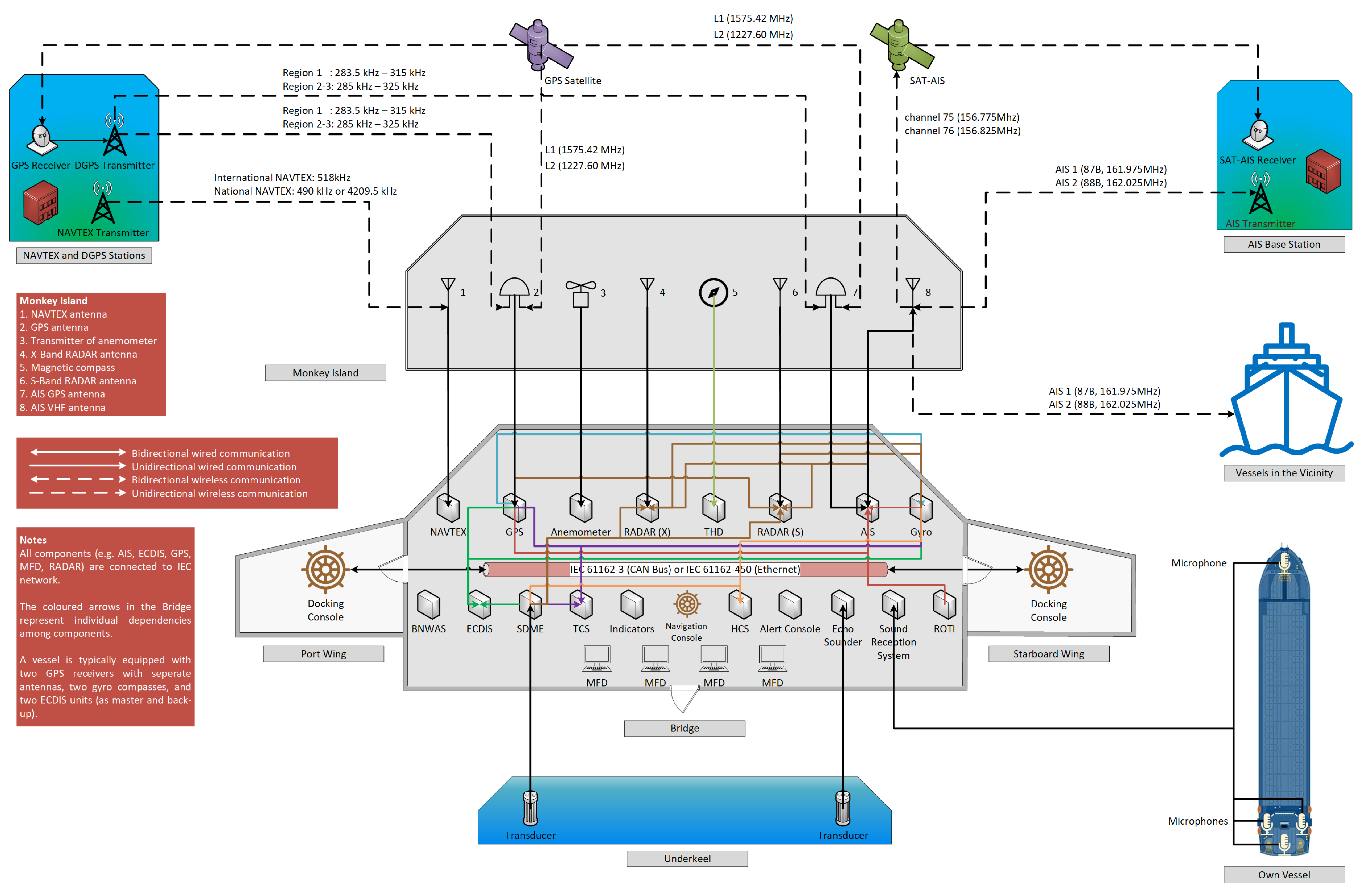
3. The Composition of the INS

Flag state requirements, class requirements, features of manufacturer products, and owner decisions directly affect the equipment in the INS. Given that the IMO identifies minimum international requirements for member states, the IMO rules and regulations constitute a baseline for this study. The stakeholders must meet the minimum IMO requirements, but they are allowed to enhance their own requirements. Therefore, defining basic criteria was required to determine the list of INS components. Even so, defining a generic equipment list comprising the INS is difficult, since several variables, such as the vessel’s gross tonnage, the vessel’s type, the navigation zone, the ship construction date, the assigned navigational tasks of the INS directly affect equipment fittings onboard ships. Accordingly, these parameters were also ignored in this study.
Consequently, the INS component list was determined according to the documents mentioned in Section 2.1. Then, these components were investigated in terms of sub-components, services, data, interfaces, communication protocols, connections, and dependencies, using relevant IMO, ITU, International Organization for Standardization (ISO), and IEC standards and documents. A visual representation of the composition of the INS is depicted in Figure 1.

3.1. INS Components

Table 2 presents the INS components together with their alternative names, where applicable, and the relevant IMO document. Alternative names are used in manufacturer brochures or different IMO resources. For instance, the “Speed and Distance Measuring Device (SDMD)” is mentioned in the SOLAS regulation V/19. This device is also called “speed log” in the maritime industry [45]. Different names, other than those used in this study may also exist. References (i.e., the columns titled “IMO Document” and “Paragraph or Appendix”) may not be limited to only those given in the table.
Many IMO documents list the Electronic Position Fixing System (EPFS) [5,46,47]. The EPFS provides position information of the vessel continuously. Two groups are distinguished, namely terrestrial (e.g., enhanced Long-range Navigation (eLORAN)) and aerial (e.g., Global Navigation Satellite System (GNSS)). Several variations of the GNSS exist, such as the U.S. based-GPS, the Russia- based Global’naya Navigatsionnaya Sputnikovaya Sistema (GLONASS), China’s Běidǒu Wèixīng Dǎoháng Xìtǒng (BeiDou), and the European Union’s Galileo [48]. Only the GPS is considered in this study.
The IMO describes the performance standards of the selected components comprehensively. The functions of the selected components may be enhanced due to the latest performance standards of the INS described in Resolution MSC.252(83). The features of the selected components are briefly described below; a complete listing is available in the Appendix A.

3.1.1. Automatic Identification System (AIS)

The AIS assists the OOW in navigating safely. It transmits three types of data (i.e., static, dynamic, and voyage-related) and safety-related messages to other vessels and stations on the shore (e.g., VTS stations, AIS base stations) [47]. According to the VesselFinder.com site, 612,974 AIS-equipped vessels exist worldwide as of 16 December 2021 [49]. The AIS essentially performs the following four functions [47]:
  • identifying ships;
  • assisting in target tracking;
  • exchanging information;
  • providing additional information to assist situation awareness.
In addition to the functions listed above, the AIS is also used for Search and Rescue (SAR) operations by receiving messages from search and rescue locating devices [47]. The AIS Search and Rescue Transmitter (AIS-SART) is used for transmitting messages involving position, static, and safety information of a unit in distress [50]. Further, the AIS Emergency Position-Indicating Radio Beacon (AIS-EPIRB) and the AIS Man Overboard (AIS-MOB) function are also used for search and rescue purposes [51].

3.1.2. Anemometer

The anemometer is not only an indicator, but also a sensor to measure the wind speed, to determine wind direction and to present the obtained data to the OOW through an indicator. This indicator should be visible from the centreline conning position [52]. The “ISO 10596:2009—Ships and marine technology—Marine wind vane and anemometers” standard regulates anemometers. According to this standard, anemometers are divided into three types, namely ultrasonic waves; cup; and windmill [53]. The standard also includes performance and accuracy requirements, test and inspection standards, etc. This standard is not referred to in any IMO document.

3.1.3. Bridge Navigational Watch Alarm System (BNWAS)

The BNWAS monitors the awareness of the bridge team to prevent marine accidents. The BNWAS has three operational modes, namely “Automatic”, “Manual ON”, and “Manual OFF”. In Manual ON mode, it is continuously enabled. In Manual OFF mode, it is continuously disabled. In Automatic mode it is activated automatically whenever the heading or track control system of the vessel is in operation. The BNWAS should be reset within an interval set by the OOW. Otherwise, visual and audible alarms sound in the bridge, the back-up officer’s or/and master’s cabin, and the locations of other crew members who can take corrective action. The alarm can be reset through reset buttons, or automatically by motion detectors on the bridge. The BNWAS should also provide an Emergency Call function by means of a push-button [54].

3.1.4. Central Alert Management Human Machine Interface (HMI)

“Alert” means an abnormal situation which requires attention. Alerts are divided into three categories, namely “alarm”, “warning”, and “caution”. An “alarm” requires immediate action by the bridge team. A “warning” indicates a changed condition that may cause danger if no action is taken. “Caution” gives information about an out-of-the-ordinary condition. The bridge teams are informed of “Alarms” and “Warnings” through visual announcement and audible signals. They are informed of “Cautions” only through a steady visual indication [7]. Alarm indicators are called “Central Alert Management Human Machine Interface (HMI)” in Resolution MSC.252(83), where the functions of alarm indicators are enhanced. For instance, the operator should be able to monitor alarm history in the INS. Another example is that at least 20 recent alerts can be displayed in the Central Alert Management HMI [7].

3.1.5. Controls for Main Engine (M/E)

The main engine provides power for the main propulsion system of the vessel. A vessel can be equipped with one or more main engines. In particular, diesel engines are deployed on merchant vessels. Controls for revolutions per minute (rpm), load, emergency stop button, sailing modes, etc. are included in the INS.

3.1.6. Controls for Main Rudder

The essential part for the control of the rudder is the steering wheel or steering lever. The rudder angle of the ship is changed through the steering wheel or steering lever by the helmsman on the bridge. The controls should include steering override mode as well [55]. Override mode is an emergency command unit used in Autopilot mode (i.e., Heading/Track Control System) [56]. When activated, it takes over the steering control immediately without using the steering mode selector switch. In case of an autopilot failure or when immediate manoeuvre is required, the override mode is used.

3.1.7. Controls for Thruster

A vessel may be equipped with one or multiple thrusters to increase the manoeuvre capability. The thruster controls (e.g., start/stop button, load stage levers) are available on the bridge. The thrusters are mostly deployed under the bow and/or aft side of cargo vessels. However, thrusters may be placed in any place of the ship’s hull.

3.1.8. Electronic Chart Display and Information System (ECDIS)

The essential function of the ECDIS is to support safe navigation. It should allow route planning, route monitoring, and positioning as an alternative to the paper chart. Voyage records should be also stored. Independent ECDIS back-up may be arranged to ensure safe navigation in case of a potential ECDIS failure. The performance standards of the ECDIS vary with the installation date. The latest performance standards of the ECDIS are described in Resolution MSC.232(82); these are applicable to the ECDIS systems that were installed on or after 1 January 2009 [57].
The ECDIS is an essential component for digital navigation in contemporary maritime, as its use reduces the workload of an OOW [57]. Navigation safety is also enhanced, as the ECDIS provides the OOW with real-time navigation information, such as position of own vessel and all chart information. Moreover RADAR layout, RADAR tracked target information, and AIS data may be displayed on the ECDIS screen [57]. Two ECDISs are deployed in the bridge of modern vessels, as primary and back-up. If the back-up ECDIS does not exist, paper charts should be in place. An updated electronic chart of the navigation zone should be imported to the ECDIS.

3.1.9. Echo Sounder

The echo sounder is designed to measure and present graphically the depth of water under the ship [58]. Performance standards for the echo-sounder are divided into two classes. If the echo-sounder is installed on or after 1 January 2001, it must comply with the MSC.74(69) Annex 4 [58]. If the echo-sounder is installed before 1 January 2001, it must comply with the A.224(VII) [59]. There are several differences in the aforementioned IMO circulars, such as range of depth, pulse repetition rate, and range scales.

3.1.10. Global Positioning System (GPS)

The GPS offers satellite-based positioning, speed, and time information. It consists of three segments, namely space segment, control segment, and user segment [60]. At least 24 GPS satellites are in service, but additional satellites are operational, to enhance GPS performance [61]; since 9 January 2021, 31 GPS satellites have been operational [61]. A GPS receiver is installed on vessels for navigational purposes; this must have the capability to process the data transmitted by the DGPS [60]. The DGPS and DGLONASS are terrestrial systems to enhance position accuracy [62]. Combined GPS and GLONASS receivers may be fitted onboard ships; these should be able to process the data of DGPS and differential GLONASS (DGLONASS) as per the IMO requirements [63]. Other GNSS combinations (e.g., GPS/Baideu) are available in the market as well [64]; such combinations are called Multi-GNSS. The essential advantage of Multi-GNSS is that it improves position accuracy.
GPS performance can be also improved by a Satellite-based Augmentation System (SBAS). Several countries have their own SBAS. For instance, the European Union (EU) provides the European Geostationary Navigation Overlay Service (EGNOS); the USA operates the Wide Area Augmentation System (WAAS); Japan has the Michibiki Satellite Augmentation System (MSAS), etc. [65].
Performance standards for a GPS receiver are divided into two types. If the GPS receiver is installed on or after July 1st 2003, it must comply with Resolution MSC.112(73) [60]. If the GPS receiver was installed before 1 July 2003, it must comply with Resolution A.819(19) [66]. One of the most essential differences between these two resolutions is that Resolution MSC.112(73) specifies that the GPS receiver must generate and output to the digital interface information on the Course Over Ground (COG), Speed Over Ground (SOG), and Universal Time Co-Ordinated (UTC). The IMO also issued performance standards for combined GPS/GLONASS receivers [63,67].

3.1.11. Gyro-Compass

A gyro-compass is used to detect the direction of the vessel’s head in relation to the true (geographic) north by using physical laws, influences of gravity and the Earth’s rotation [68,69]. Magnetic compasses are deflected from external magnetic fields. However, magnetic fields do not affect gyro-compasses. This is why gyro-compasses are widely used on vessels as a primary device for the detection of the true north.

3.1.12. Heading Control System (HCS)

The Heading Control System (HCS) keeps the vessel on a preset heading by using the heading information. It should provide reliable operation under various speeds, weather, and loading conditions. The HCS may work together with the Track Control System. The standards in Resolution A.342(IX) must be met for equipment installed before 1 January 1999. On the other hand, the equipment installed on or after 1 January 1999 must comply with Resolution MSC.64(67) Annex 3 (amendment to A.342(IX)) [70].

3.1.13. Indicators

Many indicators are proposed by the IMO, namely propeller and main engine revolutions, pitch value for Controllable Pitch Propellers (CPP), torque, starting air, lateral thrust, speed, rudder angle, gyro-compass heading, magnetic compass heading, heading reminder, water depth, time, air and water temperature. Moreover, Rate-of-Turn indicator, wind direction, and velocity indicator (i.e., anemometer) are also proposed [55].

3.1.14. Magnetic Compass

The magnetic compass is installed on ships to determine and display heading information without any power supply [71]. Magnetic compasses generate several errors; for these to remain within the limits determined by the SOLAS, the compass should be mounted in a proper binnacle with correcting devices [72].

3.1.15. Multifunctional Display (MFD)

The IMO defines the Multifunctional Display (MFD) as “A single visual display unit that can present, either simultaneously or through a series of selectable pages, information from more than a single function of an INS” [6]. A task station in the bridge consists of the MFD with dedicated controls to display and operate any navigational task [6], so that individual components (e.g., RADAR and ECDIS) can be combined in one unit [73]. The OOW can switch over between the displays of the components connected in the MFD. The MFD is an essential part of the INS. However, it does not have to be used as part of the INS; it may be also deployed as dedicated equipment in conventional bridges.

3.1.16. NAVigational TEleX (NAVTEX)

The NAVigational TEleX (NAVTEX) is a communication device for vessels. It receives and automatically prints or displays the announcement of Maritime Safety Information (MSI) which are navigational and meteorological warnings, meteorological forecasts, and other urgent safety-related messages in coastal waters. It may be used by vessels of all types and sizes. The NAVTEX services are divided into two types, namely International NAVTEX and National NAVTEX. The message language for the International NAVTEX should be English, but for National NAVTEX, it should be determined by the national administration. The received messages are stored in the memory of NAVTEX for 72 h. In this way, the subsequent messages are not re-printed or re-displayed wihin this interval. The messages are classified into three priority levels, namely Vital, Important, and Routine. The priority level dictates the timing of the first broadcast of a new warning message. The Vital priority level is used for substantial cases, such as piracy activities, ship distress messages, or warnings for tsunamis. The Important priority level is used for urgent information. The Routine priority level is used for almost all types of information messages [74].

3.1.17. RAdio Detection And Ranging (RADAR)

The RADAR onboard ships is used against collision risk, and to support safe navigation. It detects shorelines and the position of obstacles, including surface vehicles and objects. A RADAR also detects the small crafts through RADAR reflectors which are used for vessels of less than 150 gross tonnage [71]. The position data of the own ship is provided by an EPFS (e.g., GPS) to the RADAR. the RADAR should be fully operational within four minutes from cold, and within five seconds from the stand-by status. RADAR systems are classified into two types, namely X-Band (9.2–9.5 GHz) and S-Band (2.9–3.1 GHz). X-Band radar provides high discrimination, good sensitivity, and tracking performance. On the other hand, S-Band radar offers higher target detection and tracking performance in adverse weather conditions (e.g., fog, rain, and sea clutter) [46].
Three performance standards are available for RADARs. If the RADAR was installed before 1 January 1999, the equipment standards must comply with Resolution A.477(XII). If the RADAR was installed on or after 1 January 1999 and before 1 July 2008, the equipment standards must comply with Resolution A.477(XII) amended by MSC.64(67) in 1996 as Annex 4. If the RADAR was installed on or after 1 July 2008, the equipment standards must comply with Resolution MSC.192(79).
The ARPA-RADAR provides continuous information about plotted targets [75]. The ARPA function is used to enhance the safe navigation capability of the vessel by reducing the workload of the bridge. As per the SOLAS requirements, the Automatic Radar Plotting Aid (ARPA) function may be mandatory for certain vessels [71].

3.1.18. Rate of Turn Indicator (ROTI)

The Rate of Turn Indicator (ROTI) determines and indicates the rate of turn, to starboard or to port, of the vessel in one minute, through an analog or alphanumeric display. It may be self-contained, or part of appropriate equipment onboard. It should be ready for operation within four minutes after switching on [76]. The ROTI is compulsory equipment for all vessels of 50,000 gross tonnage and upwards [71].

3.1.19. Rudder Pump Selector Switch

In hydraulic or electro-hydraulic steering systems, hydraulic pumps are used to move the ship’s rudder. The vessels are generally equipped with two hydraulic pumps as primary and secondary (emergency). The rudder pump selector switch provides the transition among the pumps.

3.1.20. Speed and Distance Measuring Device (SDMD)

This device is used to determine and indicate the velocity and distance-run of a vessel. It offers information on the forward speed over the ground, forward speed through the water, and distance-run. The device may also provide information regarding the ship’s motions. Resolution MSC.96(72) defines the performance standards for the equipment installed on or after 1 July 2002. If the equipment was installed before 1 July 2002 and on or after 1 January 1997, it must comply with Resolution A.824(19). If the equipment was installed before 1 January 1997, it must comply with Resolution A.478(XII) [77]. The SDMD is compulsory equipment for all vessels of 50,000 gross tonnage and upwards [71].

3.1.21. Sound Reception System

The sound reception system allows the OOW to hear and determine the direction of sounds outside the bridge. It is a mandatory navigational aid if the bridge is totally enclosed and administration does not decide otherwise [71]. It receives outside signals (70 Hz–820 Hz) and reproduces them inside the bridge for the OOW so as they can perform their look-out duty effectively. Moreover, it determines the approximate direction of the sound [78].

3.1.22. Steering Mode Selector Switch

The ship is steered by the Track Control System or Heading Control System in auto mode. Steering modes are divided into three types, namely “Auto”, “Non-Follow Up (NFU)”, and “Follow Up (FU)”. Both NFU and FU may be called manual steering modes [79]. Whereas the NFU is an open-loop control mode, the FU is a closed-loop control mode [79]. In the NFU mode, the rudder steers whilst the steering lever is held to the starboard side or port side of the vessel and remains at its current angle when the steering lever is released [80]. In the FU mode, the rudder of the vessel steers according to the given command by the helmsman [79]. The steering mode selector switch provides the transition among such modes.

3.1.23. Steering Position Selector Switch

Steering is possible from the wings (starboard and port) and the center-bridge. Steering from the wings may be beneficial for the bridge teams, especially during mooring. The steering capability may be transferred to the work station in the wings or vice versa by bridge teams. The steering position selector switch provides the transfer capability between the center and the wings.

3.1.24. Track Control System (TCS)

The Track Control System steers the ship towards a waypoint or a sequence of waypoints. The Track Control System may also have a heading control mode; either way, the performance standards for heading control systems in the SOLAS should be met [81].

3.1.25. Transmitting Heading Device (THD)

The true heading of a ship is given through the Transmitting Heading Device (THD). The “True Heading” is defined by the IMO as “horizontal angle between the vertical plane passing through the true meridian and the vertical plane passing a through the craft’s fore and aft datum line. It is measured from true north (000°) clockwise through 360°” [82]. The THD produces a signal for the true heading to other equipment onboard the ship [83]. The ships which are not equipped with the gyro-compass, and are of gross tonnage between 300 and 500 are required to carry a THD or alternative equipment which transmits heading information [82].

3.2. Communication Protocols and Interfaces

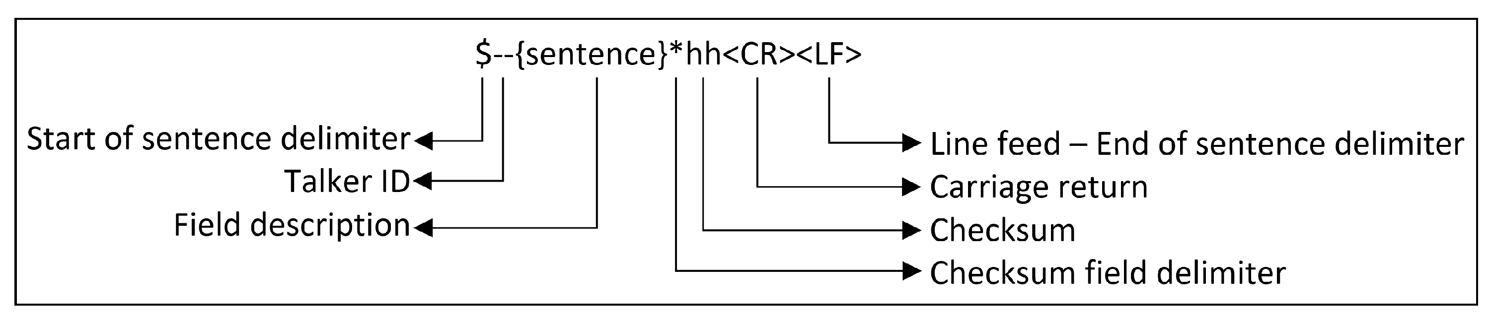
3.2.1. Non-Device-Specific

The IEC 61162 “Maritime navigation and radio communication equipment and systems—Digital interfaces” standard defines digital interfaces for navigation, radio communication, and system integration in marine vehicles. The standard consists of five sections, as follows [84]:
  • IEC 61162-1: Single talker and multiple listeners;
  • IEC 61162-2: Single talker and multiple listeners, high speed transmission;
  • IEC 61162-3: Multiple talkers and multiple listeners—Serial data instrument network;
  • IEC 61162-450: Multiple talkers and multiple listeners—Ethernet interconnection;
  • IEC 61162-460: Multiple talkers and multiple listeners—Ethernet interconnection—Safety and security.
The IEC 61162-1 is alternatively called NMEA 0183 [84]. The IEC 61162-3 is also called NMEA 2000 [18,85]. NMEA 2000 is based on CAN [17,18]. Although IEC 61162 is referred in IMO documents (e.g., MSC.112(73) [60]) as a footnote, many bridge devices are compliant with IEC standards [3].
As shown in Figure 2, an IEC 61162-1 type of message consists of several parts, namely start of sentence delimiter, talker identifier (Talker ID), and checksum. The message initiates with the $ symbol, and the talker identifier follows it. The field sentence constitutes the last part of the IEC 61162-1 sentence. The IEC 61162-1 has 124 types of field sentence formats for different data, for example “RPM—Revolutions”, “RSA—Rudder Sensor Angle”, “HCR—Heading Correction Report”. Each field sentence has its own format, and the message can be understood using the guidelines in the IEC 61162-1. Therefore, 65 types of talker identification are available in the IEC 61162-1. The talker identifier states the data source, namely GPS, GLONASS, and eLORAN.
The Inter-VTS Data Exchange Format (IVEF) is a standard framework for data exchange between maritime control centers (i.e., VTS) [86,87]. The IVEF was developed by the IALA with the contribution of Saab (HITT Traffic), Kongsberg Norcontrol IT, ATLAS Maritime Security, Transas, Japan Radio Co., Oki Consulting Solutions, Rijkswaterstaat, Sofrelog, Lockhead Martin, NaviElektro, Selex Sitemi Integrati [88].
No official document containing a list of interfaces exists; instead, manufacturer brochures for bridge equipment were used to determine interfaces in use. Such interfaces are DVI, RJ-45, RS-422, USB, RS-232, RS-485, and M12. Moreover, PL-259 or SO-239 for VHF antennas, TNC or SMA for GPS antenna are used.

3.2.2. AIS-Specific

The AIVDM (reports from other ships) and AIVDO (reports from the “own” ship) message formats are used [89,90] in the AIS. The AIS has 27 types of messages [20]. The messages are transmitted through four international frequencies to shore stations (i.e., base stations) and other ships, as follows [20]:
  • AIS 1 (Channel 87B, 161.975 MHz);
  • AIS 2 (Channel 88B, 162.025 MHz);
  • channel 75 (156.775 MHz), Message 27 transmission only;
  • channel 76 (156.825 MHz), Message 27 transmission only.
Other than those listed above, regional operating frequencies may be used [20]. Both Channel 87B and Channel 88B are used for standard operation of the AIS [20]. The AIS can transmit information over the AIS satellites; this technology is called Satellite AIS. Both Channel 75 and Channel 76 are used for the Satellite AIS [91]. Channel 75 and Channel 76 are used to send only long-range broadcast messages (i.e., “Message 27: Position report for long-range applications” [20]) to an AIS base station over an AIS satellite when the vessel is out of the coverage range of an AIS base station [20,91]. At that time, the ship continues to transmit messages through Channel 87B and Channel 88B for vessels in the vicinity. The AIS stops to transmit Message 27 within an AIS base station coverage area [20]. Channel 87B and Channel 88B are used for bidirectional transfer of AIS messages between ship and ship or between ship and AIS base station. Channel 75 and Channel 76 are only used in one-way communication to transmit Message 27 from ship to AIS satellite [91]. The AIS may use a Wi-Fi protocol (e.g., IEEE 802.11g/n, IEEE 802.11b) to allow connection with other Wi-Fi-enabled devices in the vessel, and may modify some parameters [92].
Other than AIS messages, an AIS may also transmit or receive AIS Application-Specific Messages (AIS ASMs) including, but not limited to, meteorological and hydrographic information, dangerous cargo indication, berthing data, and number of persons onboard. Displaying AIS ASMs is not a mandatory function of AIS devices. External hardware and dedicated software could be required to receive and transmit AIS ASMs. AIS ASMs may be transmitted and received by AIS devices onboard ships and AIS base stations. AIS base stations can also distribute AIS ASMs to shore-based users after receiving them. The messages are divided into two classes, namely international functional messages and regional functional messages. In particular, binary messages are used for the transmission of ASMs and the message structure is specified in Recommendation ITU-R M.1371-5 [20,93,94,95,96].

3.2.3. GPS-Specific

The GPS technology for vessels operates in the frequency bands of 1575.42 MHz, called L1, and 1227.60 MHz called L2 [60]. Additionally, the DGPS function operates in the 283.5 kHz to 315 kHz band in Region 1 and in the 285 kHz to 325 kHz band in Regions 2 and Region 3, as per the Recommendation ITU-R M.823 [21,97]. The regions are shown in Figure 3 [98].

3.2.4. NAVTEX-Specific

The 518 kHz, 490 kHz, and 4209.5 kHz frequencies are used for NAVTEX. The International NAVTEX service is provided on 518 kHz. The National NAVTEX service is provided on 490 kHz or 4209.5 kHz. Other national frequencies may be allocated by the ITU [99].

3.3. Data

The components in an INS may produce and/or present data to the bridge team, such as geographic location, COG, SOG, and heading. The data may be presented in analog or digital form. Moreover, a component transmits the produced data to other components using communication protocols as mentioned in Section 3.2. Details on data provided by each INS component, including the direction of data flows among such components are given in the Appendix A.

3.4. Sub-Components

INS components have hardware and/or software sub-components. Even though the IMO defines minimum performance standards for the components, sub-components are not defined. Accordingly, manufacturers’ products were analyzed to identify sub-components; this means that optional sub-components may be available in the market. The essential sub-components of the INS components are shown in the Appendix A and briefly discussed in the sequel.
The AIS works in connection with one GPS antenna and one VHF antenna [47,100,101]. However, combined antennas are available in the market today [100]. Some administrations require a connection for pilots at the bridge front [47]. The class A type AIS has a pilot input/output port [101]. A plug should be connected to such a port on the bridge by which pilots can connect their Personal Pilot Unit (PPU) [101]. Wi-Fi routers specifically developed for the AIS (e.g., Transas Pilot AIS Wifi Interface) are available in the market to create a Wi-Fi network via pilot plug [102]. By using mobile applications (e.g., Wärtsilä Pilot PRO), broadcasting data from a Wi-Fi router can be gathered and presented to the user [102].
The GPS should have the capability to process DGPS signals [60]. The GPS and DGPS combined antennas are available in the market as Furuno GPA-021S, or GPA-023S antennas [103]. Other combinations are also possible; for instance, Multi-GNSS antennas (e.g., combination of GPS and GLONASS) are available in the market, such as Furuno GPA-022S and GPA-023S [103]. Nowadays, Multi-GNSS antennas are commonly installed onboard ships.
The IMO allows alternative reset functions other than reset buttons for the BNWAS [54]. The alarm may be raised by the crew moving in the bridge, and it is possible to find BNWASs with motion detectors in the market [104].
Some bridge equipment, such as ECDIS and RADAR require operating systems to work. Different operating systems are used, namely Linux [11], Microsoft Windows Embedded Standard 7 [105], Microsoft Windows Compact Embedded [105], Microsoft Windows 7 Professional [106], Microsoft XP Embedded [107].
The ECDIS requires electronic charts to work. Electronic charts of the ECDIS are divided into two types, namely Raster Navigation Chart (RNC); and ENC. The RNC is facsimiled from paper charts, whilst the ENC is created on computers directly [57]. The ENC is widely used onboard ships, compared to RNC. The charts in use should be the latest edition and approved [57]. Accordingly, electronic charts require updates and can be updated through a USB stick, internet connection, or CD-ROM.

3.5. Connections and Dependencies

The INS is based on showing information on the MFD, and the compulsory connections to the MFD vary according to allocated navigational tasks (e.g., collision avoidance, route planning). The required connections to the MFD should be determined according to specific navigational tasks, using resolution MSC.252(83). The INS requirements do not strip down the individual dependencies among the equipment, but may increase the number of connections. For instance, displaying MSI messages provided by NAVTEX is mandatory for the optional navigational task of “status and data display” [5]. Equipment are allowed to be connected to each other beyond the IMO requirements. Table 3 depicts the dependencies between individual components as per the IMO requirements. The symbols and in the table stand for “OR”. Some equipment may not be mandatory as per the IMO requirements. In these cases “OR” is used in the table. The symbol for the ECDIS means that the primary heading sensor is gyro-compass, but if the vessel is not fitted with gyro-compass, the ECDIS requires the THD. The symbol stands for “depends”; for example, the AIS depends on “GPS”, “ROTI”, and “gyro-compass or THD”.
The IMO does not specify which sensor should be used by the THD to determine the true heading. However, the “ISO 22090: Ships and marine technology—Transmitting heading devices (THDs)” standard specifies the THD. This standard consists of three parts, namely 22090-1 Part: 1 Gyro-compasses, 22090-2 Part 2: Geomagnetic principles, and 22090-3 Part 3: GNSS principles. Part 1 directly mentions gyro-compass standards. Part 2 mentions the combination of magnetic compass and THD. Part 3 mentions the combination of GNSS (e.g., GPS, GLONASS, GALILEO) and THD. All three parts also in their Annexes clearly give equivalent requirements in ISO 22090 and IMO Resolution MSC.116(73).
A reference to the gyro-compass is made in Resolution A.424(XI), which states that “Means should be provided for correcting the errors induced by speed and latitude” [69]. Even though it is not explicitly defined in the resolution, the gyro-compass depends on the GPS to correct the speed deviation. Moreover, a GPS provides information on the ship’s latitude to the gyro-compass [108].
The AIS may have a long-range feature [47,109]. The long-range feature offers AIS information exchange capability via ship satellite-based communication systems at the out-of coverage range of base stations. If this feature is available and is desired to be activated, the AIS requires to be connected to the satellite-based communication system of the ship, such as the Inmarsat-C and Medium Frequencies/High Frequencies (MF/HF) part of the Global Maritime Distress Safety System (GMDSS) [20,101].
According to the IMO, “The ship’ s position should be continuously monitored by a second independent position source” [59]. Therefore, with reference to the Track Control Unit, the second equipment may be a second GPS.
Alert management is essential for the INS. All connected equipment to the INS should be part of the alert management. If the BNWAS is installed, it should be connected to the alert management. Moreover ([7]) “All systems, sources and sensors incorporated, connected in the INS should be part of the alert management. The following equipment and systems, if installed, and not incorporated in the INS should be also included in the alert management as far as possible:
  • heading information system (e.g., Gyro compass);
  • heading/track control system;
  • electronic position-fixing systems (e.g., GPS);
  • speed and distance measuring equipment;
  • radar with target tracking functions;
  • ECDIS;
  • AIS;
  • echo sounding equipment;
  • GMDSS equipment (e.g., NAVTEX);
  • relevant machinery alarms for early warning."

4. An INS Cyber-Physical Range

According to [110], “Cyber ranges are interactive, simulated representations of an organization’s local network, system, tools, and applications that are connected to a simulated Internet level environment. They provide a safe, legal environment to gain hands-on cyber skills and a secure environment for product development and security posture testing.” Accordingly, a testbed with functionality allowing the testing of the security posture of cyber-physical systems, such as the INS, would constitute a “cyber-physical range”.
A cyber-physical range can be used for training, as it provides a controlled, interactive technology environment where trainees can learn how to detect and mitigate cyber attacks using the same kind of equipment that exists in the real world. The cyber-physical range allows attacks against the INS to be simulated, and to monitor a trainee’s progress and performance in reacting to them; this also includes the assessment of how well a team executes incident response plans. Beyond training, a cyber-physical range can be used to experiment with new cyber defense technologies, as it provides a safe environment to solve complex cybersecurity problems where new ideas can be tested and the interaction of humans with emerging cybersecurity solutions can be assessed. Further, the cyber-physical range can be used to test the effectiveness and efficiency of existing, established cybersecurity solutions when applied in a specifically configured environment.
A reference architecture for a cyber-physical range and an outline of its instantiation for testing the cybersecurity posture of marine navigation systems were proposed in [111]. In this section, a more detailed specification of such a cyber-physical range for the INS is provided.

4.1. Capabilities and Functionalities

A cyber-physical range can be developed for the rapid test of hardware and software components both for INS concept and conventional bridges [27]. The performance of the components can be tested as per the requirements in maritime regulations (e.g., performance standards defined by the IMO) [34]. The range can be used for risk assessment, as well [31,33]. It should provide a direct connectivity feature for Verification and Validation (V&V)-related equipment, such as RADAR, echo sounder, sensor of rpm of the engine, sensor of rudder angle, or actuator through sensor box [34]. The V&V can be conducted with different methods, such as requirement-based tests, fault injection tests, simulation-based, or vessel in the loop architecture [34]. The range should be possible to be used as a mobile test environment [8]. Therefore it should be possible to be used for early testing of developing maritime technologies [26]. Such a range may be also used for research and development activities, such as bridge design, traffic management, autonomous vessels, remote pilotage, and situation detection [28].

4.2. Standards and Frameworks

The communication-related standards (e.g., IEC 61162) were discussed in Section 3.2. In this section we discuss other relevant standards and frameworks that need to be incorporated in the testbed.
The S-100 Universal Hydrographic Data Model (UHDM) was developed by the International Hydrographic Organization (IHO). The S-100 UHDM is a framework document to develop digital services and products for the hydrographic, maritime, and the Geographic Information Community (GIS) communities [112]. The S-100 is used in various products, such as the Electronic Navigation Chart (ENC) of the ECDIS [34].
The High-Level Architecture (HLA) is an architecture for integrated and distributed simulation [34]. The HLA is defined in the IEEE Standard 1516 entitled “IEEE Standard for Modeling and Simulation (M&S) High-Level Architecture (HLA)—Framework and Rules” which could be used for communication middleware and a simulation architecture, such as sensor simulation and environment simulation [34]. The Object Model Template (OMT) offers a framework for the communication between simulations created with the HLA [33].
The Video Electronics Standards Association (VESA) is an international non-profit organization with more than 285 corporate members worldwide [113]. One of the standards developed by the VESA is the mounting interface standard for screens [114]. The screens used in a testbed with the VESA standards are useful for connection to universal mountings [8].
If the range is to be transportable in containers [23,25], these must comply with Container Safety Convention (CSC) standards to be certified for international transportation [115].
The “ISO 17894: Ships and marine technology—Computer applications—General principles for the development and use of programmable electronic systems in marine applications” standard provides 20 principles for the development and testing of Programmable Electronic Systems (PES) in marine applications specifically [116]. The requirements stated in the standard may be considered during the development process of the range [29].
A range may consist of several structures. A communication link is required between structures. Other than cabling, wireless communication can be used, as well. Long-Term Evolution (LTE) is a type of cellular network with 100 Mbps download and 50 Mbps upload [117], and it is possible to use in testbeds [26,28], as it is adequate for reliable broadband communication. Different communication protocols other than LTE, such as TCP, User Datagram Protocol (UDP), Local Area Network (LAN), Wireless Local Area Network (WLAN), Wide Area Network (WAN) [27,28,34] can be also used in the range. Today, advanced cellular network technologies such as 5G, which offers lower latency, higher capacity, and increased bandwidth [118] are available. Exploring these allows for more onboard applications to be managed and monitored from shore. Moreover, such advantages are of importance in developing e-navigation technologies such as ongoing autonomous ship projects.

4.3. Hardware Components

A virtual INS testbed can also be developed. A ship control unit [119] and a trackball mouse may be used to manage such a virtual testbed [28]. Multitouch screens (e.g., ELO 2244L [120,121] can be used for the control and monitoring of virtual elements, such as lights, machine telegraph, or GPS [8]. For navigation software in particular, larger screens may be preferred. Curved screens are useful for better visibility [8]. The screens can be connected via the daisy chain [8].
Not only laptops, but also industrial computers can be used for an INS testbed. As an example in the eMIR platform an industrial computer (Nuvo 3000E [121,122]) involving an Intel I7 processor, 8GB RAM, Solid State Hard Drive (SSD) was used [8]. SSD-type hard discs have several benefits, such as shock resistance, low power usage, and reduced heat generation [123]. Particularly the shock resistance advantage is essential for the mobility of testbeds. Accordingly, shock and vibration-proof computers [124] could be also preferred.
The onboard sensors can be classified into three groups, namely movement sensors, environmental sensors, and internal ship sensors [36]. Real sensors, such as AIS, wind sensor (i.e., anemometer), microphones for acoustic analysis, video camera, Inertial Measurement Unit (IMU), RADAR, GPS or DGPS, speed log, engine sensors (e.g., rpm, pressure, temperature), rudder angle indicator, NAVTEX, and gyro compass can be used in the testbed [25,30]. Many bridge sensors are inherently available on ships. Hence, a vessel in service may be utilized to receive data from her sensors [30].
A mobile connectable sensor box with several marine and surveillance equipment, such as RADAR pole (e.g., SIMRAD Broadband 4G RADAR [125]), RADAR connector, AIS (e.g., SIMRAD NAIS-400 [126]), VHF antenna, anemometer, compass, GPS antenna, visual camera, infrared camera, ultraviolet camera can be developed. In this way, the objects at sea as well as environmental conditions at the shore or onboard can be tracked and monitored. GPS antenna, VHF antenna, and stated antennas’ connectors are required for an AIS. The data in the sensor box may be transmitted through an LTE router consisting of an LTE antenna and an LTE connector. For energy, an electrical accumulator and recharger may be used. A computer could be required to manage the subject sensor box [28,33,34,35].
An experimental VTS infrastructure on the shore side could be developed to represent marine traffic situation by receiving the data from sensor simulation or real marine devices like AIS [27,28]. It is a fixed installation with computers, monitors, and multitouch display components [28,31].
A geographic sea location can be defined as the test zone. The zone may be fitted with surveillance technologies, such as AIS, RADAR, camera, wind sensor. The data could be transmitted to the research center for instant monitoring through communication technologies like LTE. In the zone, new e-navigation technologies may be safely tested [33,35,36].
Cable ducts are used for organizing the cables used in an INS testbed [8]. A face plate can be used for external power supply (e.g., SNT HRP 300 12 [121]) and network interface [8]. A power supply module converts input power according to the requirements of the bridge elements to be powered. A network switch (e.g., Ha-Vis Econ 2030B-A [121]) is a high-speed networking device which receives Transmission Control Protocol/Internet Protocol (TCP/IP) data packets, and then transmits received data to other devices in the network [127].
Tripods could be used to fasten up the screens. Flight cases or rugged cases may be preferred for a light and safe mobility of screens, computers, and similar hardware used in the testbed [8].
The range could be kept ready for transportation. To this end, 10-foot or 20-foot containers may be used [25].

4.4. Monitoring and Management Tools

The OpenCPN is a free chart plotter and navigational software for use underway or as a planning tool [128]. The Open Nautical Charts as free seacharts could be used in the OpenCPN [129]. The OpenCPN can be used for the AIS tracking function in the testbed [26,35]. A RADAR tracking software (e.g., developed by Cambridge Pixels) can be used to identify RADAR tracks and to process video [36]. The data flows among the components can be controlled by a message broker software like RabbitMQ, which is open source and widely used [130]. The sensor box may require RADAR tracking software and RabbitMQ [35]. In addition to these, specific software like the Navibox Software that gathers and handles sensor data in the eMIR platform may be required [35].

4.5. Simulation, Emulation, and Analysis Tools

The Bridge Command, which is an open-source ship simulator software for Windows, Linux, and macOS, operating systems is used in the eMIR [8,131]. Compatible strings with NMEA 0183 are broadcasted by the Bridge Command. Moreover, detailed guidelines are available to extend the functions of the Bridge Command [121,132,133]. The Orocos Toolchain can be used to manage data received from sensors [134].
The MATLAB Simulink allows simulation, continuous test, automatic code generation, and verification of embedded systems [135]. The developed model can run on the MATLAB Simulink [32]. The Simulink Real-Time is used to create real-time applications from the Simulink model [136].
Various virtual bridge elements that control and monitor the bridge console, such as bow thruster, main propulsion, conning, heading indicator GPS, VHF, light controls, machine telegraph, steering lever, rudder angle indicator can be developed [8].
The Cognitive Architecture for Safety Critical Task Simulation (CASCaS) in the eMIR platform is a Windows-based software to simulate human behavior such as a navigator on a ship bridge [137]. A virtual user interface as a user interface representation in the CASCaS may be developed [33,138].
A simulation tool for marine traffic may be developed to implement, execute, and observe the motion of multiple vessels and the effects of environmental conditions (e.g., waves, currents, and winds) in a realistic marine environment [31,37].
Development of a tool like the Distributed Controlling Toolkit (DistriCT) could be pretty useful for three tasks, namely program control, simulator control, and simulation assessment. Program control is to set simulation components. Simulation control is to manage simulation behavior. Simulation assessment is to access and analyze the simulation states [37].
The behavior of rigid objects (e.g., cargo) in the simulated environment can be simulated by an N-Body simulator [31]. Software for socio-technical analysis including bridge, crew, and organizational aspects can be developed [33].
By using an eclipse-based editor, an initial static scene consisting of essential components, actors, and environmental factors in accordance with the pre-defined scenario can be developed. For instance, a 3D vessel can be inserted into the scene [23,37].
Unreal Engine is a comprehensive solution for real-time 3D creation and is used in many industries, such as games, architecture, automotive, film, training, simulation [139]. Due to its performance and graphics quality, Unreal Engine can be used to illustrate real-time ship motions in the simulation environment [140].

4.6. Cybersecurity-Specific Components

Real equipment mentioned in Section 3.1 may be used for cybersecurity research. Even though the use of real equipment in a testbed can be costly, it is useful to create a realistic test environment. Other than real equipment, some software, such as Bridge Command [131], or NMEA Simulator [141] could be utilized to transmit mimic IEC 61162-1 (i.e., NMEA 0183) messages [8]. The NMEA Simulator consists of 18 types of IEC 61162-1 message. The Bridge Command consists of 10 types of IEC 61162-1 message. Given that 124 types of message are available in the standard [84], the capabilities of the testbed could be limited due to few number of mimic messages transmitted by both software. However, the test capability could be extended with alternative free or paid software (e.g., NemaStudio [142]). For AIS research, the AIS BlackToolkit consists of several features, such as the AIVDM message encoder [143]. Moreover, AIS data offered by service providers can be used in a cyber-physical range. For instance, the Norwegian Coastal Administration provides local AIS data in real-time free of charge over an IP address and port number [144]. As an open source chartplotter, the OpenCPN [128] which is compatible with the Bridge Command, could be used [35,145]. In the testbed, vulnerability scanners (e.g., Nessus Professional [39]) may be utilized to detect vulnerabilities of components and network [105]. An INS network may be created using network simulation tools (e.g., OPNET Network Simulator [146]) [147]. The Kali Linux is a Debian-derived Linux operating system and comes with more than 300 tools related to information security and penetration testing [148]. These convenient tools can be used on the network for security analysis. For instance, one of the pre-installed tools is Wireshark [149], which could be used to monitor and analyze the network in real-time [150].

5. Conclusions

Technological advancements are crucial in enhancing marine safety. In addition to safety, digital infrastructure and obtained data contribute to the protection of the marine environment and increase the efficiency of the maritime economy. The need for e-navigation testbeds has been acknowledged by the IMO, and some of such developed testbeds have been recognized by the IALA. A testbed allows the testing and development of maritime systems in a safe and economic environment. As cybersecurity concerns in the maritime sector are rising, it is also important to be able to assess the cybersecurity posture of the INS in the controlled environment that a testbed provides; such a testbed should have cybersecurity testing functionality that qualifies it as a cyber-physical range. In this paper we reviewed publications on bridge testbeds to identify tools, capabilities and functions, standards and frameworks, architectural models used. Moreover, we identified technical aspects of the INS, including devices, sub-components, interfaces, communication protocols, data, dependencies, and connections, by considering in-force IMO rules and regulations and international standards. A total of 25 INS components were found, including ECDIS, AIS, RADAR, MFD, etc. We used these results to define design specifications for an INS Cyber-Physical Range.

Author Contributions

Conceptualization, A.O. and V.G.; methodology, A.O. and V.G.; validation, A.O.; investigation, A.O.; writing—original draft, A.O.; writing—review and editing, S.K. and V.G.; visualization, A.O.; supervision, V.G.; project administration, V.G.; funding acquisition, S.K. and V.G. All authors must be limited to those who have contributed substantially to the work reported. All authors have read and agreed to the published version of the manuscript.

Funding

This paper has received funding by the Research Council of Norway through the Maritime Cyber Resilience (MarCy, project number 295077) project, and through the Norwegian Centre for Cybersecurity in Critical Sectors (NORCICS, project number 310105). The content reflects only the authors’ views, and neither the Research Council of Norway nor the project partners are responsible for any use that may be made of the information it contains.

Institutional Review Board Statement

Not applicable.

Informed Consent Statement

Not applicable.

Data Availability Statement

Not applicable.

Acknowledgments

Not applicable.

Conflicts of Interest

The authors declare no conflict of interest.

Appendix A

Selected equipment, their sub-components, functions, produced/transferred data, and required data flow are shown in Table A1.
Table A1. Selected equipment with details of sub-components, functions, and data.
Equipment and Sub-ComponentsServiceDataRequired Data Flow
AIS
  • Framework
  • Minimum Keyboard and Display (MKD)
  • Pilot plug
  • GPS antenna
  • VHF antenna (possible to be used GPS and VHF combined antenna)
identifying ships, assisting in target tracking, assisting in search and rescue operation, information exchange, providing additional information to assist situation awareness [47]Static Data: MMSI, Callsign and name, IMO number, Length and beam, Type of ship, Location of EPFS antenna
Dynamic Data: Ship position, Position time stamp in UTC, COG, SOG, Heading, Navigation status, Rate of turn
Voyage related Data: Ship’s draught, Hazardous cargo type, Destination and ETA, Route plan
Safety messages [47]
Sends to: RADAR [46]
Anemometer
  • Transmitter
  • Display Unit
detecting and indicating wind speed and directionwind speed and direction [52]
BNWAS
  • Control panel
  • Processor unit
  • Reset panels
  • Visual flash
  • Bridge buzzer
  • Cabin buzzers
  • Motion detectors (optional)
monitoring bridge activity, detecting operator disability and then alerting automatically [54]awareness of OOW [54]
Central Alert Management HMI
  • Display/Control unit
reporting abnormal situation which requires an attention [55]provides acknowledged, unacknowledged or normal condition [55]Receives from: sensors connected
Controls for M/E
  • Display/Control unit
Control buttons or levers of main engine for different purposes such as rpm, load, emergency stop button, sailing mode selection button, and so onfunctional data as to main engine
Controls for main rudder
  • Override unit
  • Steering wheel/Steering lever
commanding the rudder angel, activating the override moderudder command, override mode status
Controls for thruster
  • Display/Control unit
  • Command lever
commanding the thrusters such as starting, stopping, load/stage, etc.indicating load/stage of thruster
ECDIS
  • Monitor unit
  • Processor unit
  • Control unit
  • ENC/RNC
  • Operating system
  • ECDIS software
offering the functions of route planning, route monitoring and positioning for officers in ECDIS instead of paper charts [57]provides data regarding route planning, route monitoring, navigational elements and parameters such as own ship’s position, past track with time marks, planned course and speed, planned position with date and time, waypoint, distance to run, own ship’s safety contour, coastline, and so on [57]Receive from: GPS, gyro compass, speed and distance measuring device. If the ships aren’t equipped with gyro compass, ECDIS receives data from the transmitting heading device [57]
Echo Sounder
  • Display/Control unit
  • Framework
  • Transducer
  • Transreceiver unit
measuring the depth of water under the ship, and presenting graphically [58]measured depth of water under a ship [58]
GPS
  • Receiver and processor
  • Framework
  • GPS antenna (possible to be used combined antennas, such as GPS+GLONASS and GPS+BeiDou)
providing space-based positioning, velocity and time system [60]position information in latitude and longitude of the vessel, UTC, SOG, COG [60]Sends to: AIS [101], RADAR [46], ECDIS [57], Heading control system [70], Track Control System [81], Gyro compass [108]
Gyro-compass
  • Gyroscope
  • Control unit
  • Repeater
determining the direction of the ship’s head in relation to geographic (true) north [69]direction of the ship’s head in relation to (geographic) true north [69]Sends to: AIS [101], RADAR [46], ECDIS [57], Heading control system [70], Track control system [81]
Receives from: GPS [108]
Heading Control System
  • Display/Control unit
  • Processor unit
keeping the vessel in preset heading by using heading information [70]steering mode, heading source, preset heading value [70]Receives from: Gyro compass or Transmitting Heading Device. Moreover, GPS or SDMD [70]
Indicatorsshows data or status information received from sensorseveral data/status such as propeller and main engine revolutions, pitch value for Controllable Pitch Propellers (CPP), torque, starting air, lateral thrust, speed, rudder angle, gyro-compass heading, magnetic compass heading, heading reminder, water depth, time, air and water temperature, wind direction and velocity [55]Receives from: Sensors connected.
Magnetic Compass
  • Binnacle
  • Compass
  • Azimuth reading device
determining and displaying the ship’s heading without any power supply [71]indicating the direction of the ship’s head in relation to magnetic north [151]Sends to: THD
Multifunctional Display (MFD)
  • Display unit
  • Control unit
  • Processor unit
  • Operating system
A display unit presents information from more than a single function of the INS [6]displays data and graphic depending on connected equipmentdepends on connected equipment
NAVTEX
  • Control unit
  • VHF antenna
  • Integrated printing device, or dedicated display device with printer output port, or a connection to INS
receiving and automatically printing or displaying MSI [99]navigational warnings, meteorological warnings, ice reports, search and rescue information, piracy warnings, tsunamis and other natural phenomena, meteorological forecasts, pilot and VTS service messages, AIS service messages (non navigational aid), LORAN messages, GNSS messages regarding PRN status, Other electronic navigational aid system messages, other navigational warnings [99]
RADAR
  • Processor unit
  • Control unit
  • Display unit
  • Operating system
  • Radar software
  • Antenna (X-Band, S-Band, or combined antenna)
indication, in relation to own ship, of the position of other surface craft, obstructions and hazards, navigation objects and shorelines [46]target tracking information, positional data derived from own ship’s position (EPFS), geo referenced data [46]Receives from: AIS, GPS, Speed and Distance Measuring Device. Moreover, Gyro compass or Transmitting Heading Device [46]
ROTI
  • Indicator (analogue or alphanumeric display)
  • Rate Gyro
indicating rates of turn to starboard and to port of the ship to which it is fitted [76]indicates the rate of turning of a ship within 1 min [76]Sends to: AIS [101]
Rudder pump selector switch
  • Switch
selection of primary and secondary (emergency) hydraulic or electro-hydraulic pumps for rudder direction.indicating primary and secondary (emergency) hydraulic or electro-hydraulic pump for rudder
Sound reception system
  • Loudspeaker
  • Microphone
  • Main unit
offers the OOW who can hear and determine the direction of the sound signals of the vessels nearby [71]sound direction [71]
Speed and Distance Measuring Equipment
  • Display/Control unit
  • Processor unit
  • Framework
  • Transducer
measuring and indicating speed and distance of the vessel [77]distance run speed of the vessel overground or speed of the vessel through water [77]sends to: Heading control system [70], RADAR [46], ECDIS [57], Track control system [81]
Steering mode selector switch
  • Switch
selection of steering modes, such as “Auto”, “Non-Follow Up”, or ”Follow Up”.active steering mode (i.e., “NFU”, “FU”, and ”Auto”).
Steering position selector switch
  • Switch
determining the active steering workstation (i.e., port wing, starboard wing or center)active steering workstation (i.e., port wing, starboard wing or center)
Track Control System
  • Display/Control unit
  • Processor unit
Track control system keeps the vessel on a pre-planned track over ground by using position, heading and speed information of the vessel [81]mode of steering; sources of actual position, heading and speed; status and failure of sensors (if any); track course and actual heading; actual position, cross track distance and speed; TO-waypoint and NEXT-waypoint; time and distance to TO-waypoint; next track course; and selected track identification [81]Receives from: GPS, Speed and Distance Measuring Equipment, Gyro compass [81]
Transmitting Heading Device
  • Compass sensor
  • Display/Control unit
  • Processor unit
indicating ship’s true heading by means of magnetic compass [82]ship’s true heading [82]Receive from: magnetic compass Sends to: AIS [101], Heading control system [70], Track control system [81], ECDIS [57], RADAR [46]

Note

1
The IALA-recognized e-navigation testbeds are listed on https://www.iala-aism.org/technical/e-nav-testbeds/, accessed on 4 October 2021.

References

  1. EMSA. Annual Overview of Marine Casualties and Incidents. Available online: http://www.emsa.europa.eu/newsroom/latest-news/item/4266-annual-overview-of-marine-casualties-and-incidents-2020.html (accessed on 6 August 2021).
  2. IMO. Resolution MSC.467(101) Guidance on the Definition and Harmonization of the Format and Structure of Maritime Services in the Context of E-Navigation; IMO: London, UK, 2019. [Google Scholar]
  3. IMO. MSC.1/Circ.1595 E-Navigation Strategy Implementation Plan—Update 1; IMO: London, UK, 2018. [Google Scholar]
  4. IMO. Resolution A.915(22) Revised Maritime Policy and Requirements for a Future Global Navigation Satellite System (GNSS); IMO: London, UK, 2001. [Google Scholar]
  5. IMO. Resolution MSC.252(83) Amended in 2018, Adoption of the Revised Performance Standards for Integrated Navigation Systems (INS), Introduction, Contents, Module A-B; IMO: London, UK, 2007. [Google Scholar]
  6. IMO. Resolution MSC.252(83) Amended in 2018, Adoption of the Revised Performance Standards for Integrated Navigation Systems (INS), Appendices; IMO: London, UK, 2007. [Google Scholar]
  7. IMO. Resolution MSC.252(83) Adoption of the Revised Performance Standards for Integrated Navigation Systems (INS), Module C-D; IMO: London, UK, 2007. [Google Scholar]
  8. Stratmann, T.C.; Gruenefeld, U.; Hahn, A.; Boll, S.; Stratmann, J.; Schweigert, S. Mobile Bridge—A portable design simulator for ship bridge interfaces. Trans. Nav. Int. J. Mar. Navig. Saf. Sea Transp. 2018, 12, 763–768. [Google Scholar] [CrossRef]
  9. IMO. MSC.1/Circ.1494 Guidelines on Harmonization of Testbed Reporting; IMO: London, UK, 2014. [Google Scholar]
  10. Svilicic, B.; Rudan, I.; Jugović, A.; Zec, D. A Study on Cyber Security Threats in a Shipboard Integrated Navigational System. J. Mar. Sci. Eng. 2019, 7, 364. [Google Scholar] [CrossRef] [Green Version]
  11. Lund, M.S.; Gulland, J.E.; Hareide, O.S.; Jøsok, ∅.; Weum, K.O.C. Integrity of Integrated Navigation Systems. In Proceedings of the 2018 IEEE Conference on Communications and Network Security (CNS), Beijing, China, 30 May–1 June 2018; pp. 1–5. [Google Scholar] [CrossRef]
  12. Lund, M.S.; Hareide, O.S.; Jøsok, ∅. An attack on an integrated navigation system. Necesse 2018, 3, 149–163. [Google Scholar]
  13. Navis Arca. About Us. Available online: https://navisarca.com/ (accessed on 4 October 2021).
  14. Cydome. Solutions. Available online: https://cydome.io/solutions/ (accessed on 4 October 2021).
  15. IMO. The IMO-Vega Database. Available online: https://www.imo.org/en/publications/Pages/IMO-Vega.aspx (accessed on 6 August 2021).
  16. IMO. Resolution MSC.86(70) Annex 3 Recommendation on Performance Standards for an Integrated Navigation System (INS); IMO: London, UK, 1998. [Google Scholar]
  17. Luft, L.A.; Anderson, L.; Cassidy, F. NMEA 2000 A Digital Interface for the 21st Century. In Proceedings of the 2002 National Technical Meeting of The Institute of Navigation, San Diego, CA, USA, 28–30 January 2002; pp. 796–807. [Google Scholar]
  18. Krile, S.; Kezić, D.; Dimc, F. NMEA Communication Standard for Shipboard Data Architecture. OUR SEA Int. J. Marit. Sci. Technol. 2013, 60, 68–81. [Google Scholar]
  19. ITU. About International Telecommunication Union (ITU). Available online: https://www.itu.int/en/about/Pages/default.aspx (accessed on 6 August 2021).
  20. ITU-R. M.1371-5: Technical Characteristics for an Automatic Identification System Using Time-Division Multiple Access in the VHF Maritime Mobile Band. 2014. Available online: https://www.itu.int/rec/R-REC-M.1371-5-201402-I/en (accessed on 6 August 2021).
  21. ITU-R. M.823: Technical Characteristics of Differential Transmissions for Global Navigation Satellite Systems from Maritime Radio Beacons in the Frequency Band 283.5–315 kHz in Region 1 and 285–325 kHz in Regions 2 and 3. 2006. Available online: https://www.itu.int/rec/R-REC-M.823/en (accessed on 6 August 2021).
  22. Okoli, C. A guide to conducting a standalone Systematic Literature Review. Commun. Assoc. Inf. Syst. 2015, 37. [Google Scholar] [CrossRef] [Green Version]
  23. Rüssmeier, N.; Lamm, A.; Hahn, A. A generic testbed for simulation and physical-based testing of maritime cyber-physical system of systems. In Proceedings of the International Maritime and Port Technology and Development Conference and International Conference on Maritime Autonomous Surface Ships, Trondheim, Norway, 13–14 November 2019; Volume 1357. [Google Scholar] [CrossRef]
  24. Kim, D.; Ahn, K.; Shim, S.; Oh, K.; Kim, Y. A study on the verification of collision avoidance support system in real voyages. In Proceedings of the 2015 International Association of Institutes of Navigation World Congress (IAIN), Prague, Czech Republic, 20–23 October 2015; pp. 1–6. [Google Scholar] [CrossRef]
  25. Akkermann, A.; Hahn, A. Comparing simulation with physical verification and validation in a maritime test field. Int. J. Syst. Eng. 2020, 4, 18–29. [Google Scholar] [CrossRef]
  26. Hahn, A.; Noack, T. Emaritime integrated reference platform. In Proceedings of the Deutscher Luft- und Raumfahrtkongress, Braunschweig, Germany, 13–15 September 2016. [Google Scholar]
  27. Schweigert, S.; Gollücke, V.; Hahn, A.; Bolles, A. HAGGIS: A modelling and simulation platform for e-Maritime technology. In Proceedings of the INT-NAM 2014: 2nd International Symposium on Naval Architecture and Maritime, Istanbul, Turkey, 23–24 October 2014. [Google Scholar]
  28. Stasch, A.; Bolles, A.; Hahn, A. LABSKAUS—A physical platform for e-maritime technology assessment. In Proceedings of the 2nd International Symposium of Naval Architecture and Maritime, Istanbul, Turkey, 23–24 October 2014. [Google Scholar]
  29. Brinkmann, M.; Böde, E.; Lamm, A.; Maelen, S.V.; Hahn, A. Learning from automotive: Testing maritime assistance systems up to autonomous vessels. In Proceedings of the OCEANS 2017, Aberdeen, UK, 19–22 June 2017. [Google Scholar] [CrossRef]
  30. Brinkmann, M.; Hahn, A.; Hjøllo, B.Å. Physical testbed for highly automated and autonomous vessels. In Proceedings of the 16th International Conference on Computer and IT Applications in the Maritime Industries, Cardiff, UK, 15–17 May 2017. [Google Scholar]
  31. Bolles, A.; Hahn, A. Save maritime systems testbed. Annu. Navig. 2014, 21, 19–34. [Google Scholar] [CrossRef] [Green Version]
  32. Hahn, A. Simulation environment for risk assessment of e-navigation systems. In Proceedings of the ASME 2015 34th International Conference on Ocean, Offshore and Arctic Engineering, St. John’s, NL, Canada, 31 May–5 June 2015. [Google Scholar] [CrossRef]
  33. Hahn, A. Test bed for safety assessment of new e-navigation systems. Int. J. E-Navig. Marit. Econ. 2014, 1, 14–28. [Google Scholar] [CrossRef] [Green Version]
  34. Brinkmann, M.; Hahn, A. Testbed architecture for maritime cyber physical systems. In Proceedings of the 2017 IEEE 15th International Conference on Industrial Informatics (INDIN), Emden, Germany, 24–26 July 2017; pp. 923–928. [Google Scholar] [CrossRef]
  35. Brinkmann, M.; Stasch, A.; Hahn, A. Testbeds for verification and validation of maritime safety. In Proceedings of the 12th International Symposium on Integrated Ship’s Information Systems & Marine Traffic Engineering Conference, Hamburg, Germany, 31 August–2 September 2016. [Google Scholar]
  36. Brinkmann, M.; Abdelaal, M.; Hahn, A. Vessel-in-the-Loop architecture for testing highly automated maritime systems. In Proceedings of the 17th Conference on Computer and IT Applications in the Maritime Industries (COMPIT’18), Pavone, Italy, 14–16 May 2018. [Google Scholar]
  37. Hahn, A.; Gollücke, V.; Buschmann, C.; Schweigert, S. Virtual test bed for maritime safety assessment. Sci. J. Marit. Univ. Szczec. 2015, 44, 116–122. [Google Scholar] [CrossRef]
  38. The eMIR platform. Available online: http://https://www.emaritime.de/ (accessed on 5 December 2012).
  39. Tenable. Nessus Professional. Available online: https://www.tenable.com/products/nessus/nessus-professional (accessed on 4 October 2021).
  40. Awan, M.S.K.; Al Ghamdi, M.A. Understanding the Vulnerabilities in Digital Components of an Integrated Bridge System (IBS). J. Mar. Sci. Eng. 2019, 7, 350. [Google Scholar] [CrossRef] [Green Version]
  41. Oruc, A. Claims of State-Sponsored Cyberattack in the Maritime Industry. In Proceedings of the 15th International Naval Engineering Conference and Exhibition (INEC 2020), Virtual, 5–9 October 2020. [Google Scholar] [CrossRef]
  42. Lovell, K.N.; Heering, D. Exercise Neptune: MaritiMe cybersecurity training using the navigational siMulators. In Proceedings of the 5th Interdisciplinary Cyber Research Conference 2019, Tallinn, Estonia, 29 June 2019; p. 34. [Google Scholar]
  43. Tam, K.; Forshaw, K.; Jones, K.D. Cyber-SHIP: Developing Next Generation Maritime Cyber Research Capabilities. In Proceedings of the International Conference on Marine Engineering and Technology Oman 2019 (ICMET Oman), Muscat, Oman, 5–7 November 2019. [Google Scholar] [CrossRef]
  44. D’Agostino, F.; Kaza, D.; Schiapparelli, G.P.; Silvestro, F. The ShIL Project: A new laboratory infrastructure for co-simulation of multi-domain marine applications. In Proceedings of the 2020 AEIT International Annual Conference (AEIT), Catania, Italy, 23–25 September 2020; pp. 1–6. [Google Scholar]
  45. Furuno. Furuno Speed Log GS-100. Available online: https://www.furuno.com/en/merchant/speedlog/ (accessed on 6 August 2021).
  46. IMO. Resolution MSC.192(79) Adoption of the Revised Performance Standards for Radar Equipment; IMO: London, UK, 2004. [Google Scholar]
  47. IMO. Resolution A.1106(29) Revised Guidelines for the Onboard Operational Use of Shipborne Automatic Identification Systems (AIS); IMO: London, UK, 2015. [Google Scholar]
  48. Jan, S.S.; Tao, A.L. Comprehensive comparisons of satellite data, signals, and measurements between the BeiDou Navigation Satellite System and the Global Positioning System. Sensors 2016, 16, 689. [Google Scholar] [CrossRef] [Green Version]
  49. VesselFinder. Vessel Database. 2021. Available online: https://www.vesselfinder.com/vessels/ (accessed on 6 August 2021).
  50. IMO. Resolution MSC.246(83) Adoption of Performance Standards for Survival Craft AIS Search and Rescue Transmitters (AIS-SART) for Use in Search and Rescue Operations; IMO: London, UK, 2007. [Google Scholar]
  51. Ramırez, T.; Mosquera, C. Full-Duplex Operation in Two-Way Broadcast Service for Maritime Applications. Available online: http://gpsc.uvigo.es/sites/default/files/publications/1570268703.pdf (accessed on 6 August 2021).
  52. IMO. MSC/Circ.603 Annex 2 Guidelines on Display Sizes and Techniques for Navigational Purposes; IMO: London, UK, 1993. [Google Scholar]
  53. ISO. ISO 10596:2009—Ships and Marine Technology—Marine Wind Vane and Anemometers; ISO: Geneva, Switzerland, 2009. [Google Scholar]
  54. IMO. Resolution MSC.128(75) Performance Standards for a Bridge Navigational Watch Alarm System (BNWAS); IMO: London, UK, 2002. [Google Scholar]
  55. IMO. MSC/Circ.982 Guidelines on Ergonomic Criteria for Bridge Equipment and Layout; IMO: London, UK, 2000. [Google Scholar]
  56. Raytheon. Autopilot Override NFU Tiller. 2007. Available online: https://www.raytheon-anschuetz.com/fileadmin/content/Operation_Manuals/Steering_Control_NautoSteer/3432_Autopilot_Override_NFU-Tiller.pdf (accessed on 6 August 2021).
  57. IMO. Resolution MSC.232(82) Adoption of the Revised Performance Standards for Electronic Chart Display and Information Systems (ECDIS); IMO: London, UK, 2006. [Google Scholar]
  58. IMO. Resolution A.224(VII) as Amended by Annex 4 to res. MSC.74(69) Recommendation on Performance Standards for Echo-Sounding Equipment; IMO: London, UK, 1998. [Google Scholar]
  59. IMO. Resolution MSC.74(69) Adoption of New and Amended Performance Standards, Annex 4 Recommendation on Performance Standards for Echo-sounding Equipment; IMO: London, UK, 1998. [Google Scholar]
  60. IMO. Resolution MSC.112(73) Revised Recommendation on Performance Standards for Shipborne Global Positioning System (GPS) Receiver Equipment; IMO: London, UK, 2000. [Google Scholar]
  61. NCO. In Space Segment; 2021. Available online: https://www.gps.gov/systems/gps/space (accessed on 6 August 2021).
  62. Jin, M.H.; Han, Y.H.; Choi, H.H.; Park, C.; Heo, M.B.; Lee, S.J. GPS spoofing signal detection and compensation method in DGPS reference station. In Proceedings of the 2011 11th International Conference on Control, Automation and Systems, Gyeonggi-do, Korea, 26–29 October 2011; pp. 1616–1619. [Google Scholar]
  63. IMO. Resolution MSC.115(73) Adoption of Revised Recommendation on Performance Standards for Shipborne Combined GPS/GLONASS Receiver Equipment; IMO: London, UK, 2000. [Google Scholar]
  64. GPS Navigator JLR-8600/8400 | JRC (Japan Radio Co., Ltd.). Available online: http://www.jrc.co.jp/eng/product/lineup/jlr8600_8400/index.html (accessed on 27 October 2021).
  65. European GNSS Agency. What Is SBAS? 2020. Available online: https://www.gsa.europa.eu/european-gnss/what-gnss/what-sbas (accessed on 6 August 2021).
  66. IMO. Resolution A.819(19) Recommendation on Performance Standards for Shipborne Global Positioning System (GPS) Receiver Equipment; IMO: London, UK, 1995. [Google Scholar]
  67. IMO. MSC.74(69) Adoption of New and Amended Performance Standards, Annex 1 Recommendation on Performance Standards for Shipborne Combined GPS/GLONASS Receiver Equipment; IMO: London, UK, 1998. [Google Scholar]
  68. Simrad. Gyro Compass. Available online: https://www.navico-commercial.com/simradcommercial/gyrocompass/ (accessed on 4 October 2021).
  69. IMO. Resolution A.424(XI) Recommendation on Performance Standard for Gyro-Compasses; IMO: London, UK, 1979. [Google Scholar]
  70. IMO. Resolution A.342(IX) as Amended by MSC.64(67) Annex 3—Recommendation on Performance Standards for Heading Control Systems; IMO: London, UK, 1996. [Google Scholar]
  71. IMO. SOLAS Chapter V Safety of Navigation, Regulation 19 Carriage Requirements for Shipborne Navigational Systems and Equipment; IMO: London, UK, 2020. [Google Scholar]
  72. IMO. Resolution A.382(X) Magnetic Compasses Carriage and Performance Standards; IMO: London, UK, 1977. [Google Scholar]
  73. Kongsberg. K-Bridge MFD. Available online: https://www.kongsberg.com/globalassets/maritime/km-products/product-documents/k-bridge-multifunctional-operator-stations (accessed on 6 August 2021).
  74. IMO. MSC.1/Circ.1403/Rev.1 Amendments to the Revised NAVTEX Manual—Sections 7 to 15; IMO: London, UK, 2016. [Google Scholar]
  75. IMO. Resolution A.823(19) Performance Standards for Automatic Radar Plotting Aids (ARPA); IMO: London, UK, 2004. [Google Scholar]
  76. IMO. Resolution A.526(13) Performance Standards for Rate-of Turn Indicators; IMO: London, UK, 1983. [Google Scholar]
  77. IMO. Resolution MSC.96(72) Adoption of Amendments to Performance Standards for Devices to Measure and Indicate Speed and Distance; IMO: London, UK, 2000. [Google Scholar]
  78. IMO. Resolution MSC.86(70) Annex 1 Recommendation on Performance Standards for Sound Reception Systems; IMO: London, UK, 1998. [Google Scholar]
  79. China Classification Society. N-03 Steering Gear Control Systems. 2015. Available online: https://www.ccs.org.cn/ccswz/file/download?fileid=201900004000003738 (accessed on 6 August 2021).
  80. Simrad. NF80 Non Follow Up Remote. Available online: https://www.navico-commercial.com/simradcommercial/remote-controls/nf80-simrad-nfu-steering-lever/ (accessed on 6 August 2021).
  81. IMO. MSC.74(69) Adoption of New and Amended Performance Standards, Annex 2 Recommendation on Performance Standards for Track Control Systems; IMO: London, UK, 1998. [Google Scholar]
  82. IMO. Resolution MSC.116(73) Recommendation on pErformance Standards for Marine Transmitting Heading Devices (THDs); IMO: London, UK, 2000. [Google Scholar]
  83. ISO. ISO 22090-1 Ships and Marine Technology—Transmitting Heading Devices (THDs); ISO: Geneva, Switzerland, 2014. [Google Scholar]
  84. IEC. IEC 61162-1 Maritime Navigation and Radiocommunication Equipment and Systems—Digital Interfaces—Part 1: Single Talker and Multiple Listeners; IEC: Geneva, Switzerland, 2016. [Google Scholar]
  85. IEC. IEC 61162-3 Maritime Navigation and Radiocommunication Equipment and Systems—Digital Interfaces—Part 3: Serial Data Instrument Network; IEC: Geneva, Switzerland, 2008. [Google Scholar]
  86. Oyunchimeg, B.; Jeong, J.S.; Park, G.K. State-of-the-art IVEF Service based on e-Navigation System. J. Korean Inst. Intell. Syst. 2013, 23, 577–582. [Google Scholar] [CrossRef] [Green Version]
  87. IALA. Open IVEF. Available online: http://openivef.org/ (accessed on 6 August 2021).
  88. IALA. Open IVEF Contributers. Available online: http://openivef.org/?page_id=58 (accessed on 6 August 2021).
  89. Al-Khalidi, M.; Al-Zaidi, R.; Woods, J.; Reed, M.; Pereira, E. Securing Marine Data Networks in an IoT Environment. In Proceedings of the 2019 7th International Conference on Future Internet of Things and Cloud (FiCloud), Istanbul, Turkey, 26–28 August 2019; pp. 125–132. [Google Scholar] [CrossRef] [Green Version]
  90. Ifrim, C.; Iuga, I.; Pop, F.; Wallace, M.; Poulopoulos, V. Data Reduction Techniques Applied on Automatic Identification System Data. In Semantic Keyword-Based Search on Structured Data Sources; Szymański, J., Velegrakis, Y., Eds.; Springer International Publishing: Cham, Switzerland, 2018; pp. 14–19. [Google Scholar] [CrossRef]
  91. Chen, Y. Satellite-based AIS and its Comparison with LRIT. Trans. Nav, Int. J. Mar. Navig. Saf. Sea Transp. 2014, 8, 183–187. [Google Scholar] [CrossRef]
  92. Em-Trak. A200 AIS Class A/Inland Transceiver. Available online: https://em-trak.com/wp-content/uploads/em-trak-A200-user-manual-EN-v5.pdf (accessed on 6 August 2021).
  93. IMO. MSC.1/Circ.1473 Policy on Use of AIS Aids to Navigation; IMO: London, UK, 2014. [Google Scholar]
  94. IMO. SN.1/Circ.289 Guidance on the Use of AIS Application-Specific Messages—Introduction & Sections 1–10; IMO: London, UK, 2010. [Google Scholar]
  95. IMO. SN.1/Circ.290 Guidance for the Presentation and Display of AIS Application-Specific Messages; IMO: London, UK, 2010. [Google Scholar]
  96. IMO. SN.1/Circ.289 Guidance on the Use of AIS Application-Specific Messages—Sections 11–14; IMO: London, UK, 2010. [Google Scholar]
  97. IMO. Resolution MSC.114(73) Adoption of Revised Recommendation on Performance Standards for Shipborne DGPS and DGLONASS Maritime Radio Beacon Receiver Equipment; IMO: London, UK, 2000. [Google Scholar]
  98. ITU. Frequency Bands Allocated to Terrestrial Broadcasting Services. Available online: https://www.itu.int/en/ITU-R/terrestrial/broadcast/Pages/Bands.aspx (accessed on 6 August 2021).
  99. IMO. MSC.1/Circ.1403/Rev.1 Amendments to the Revised NAVTEX manual—Introductory Text, Contents, Foreword and Sections 1–6; IMO: London, UK, 2016. [Google Scholar]
  100. Furuno. Furuno AIS FA-170 Brochure. Available online: https://www.furuno.com/files/Brochure/305/upload/FA-170_E.pdf (accessed on 6 August 2021).
  101. IMO. SN/Circ.227 Guidelines for the Installation of a Shipborne Automatic Identification System (AIS); IMO: London, UK, 2003. [Google Scholar]
  102. Transas. Transas Pilot Pro User Manual. 2018. Available online: https://cdn.wartsila.com/docs/default-source/marine-documents/transas/pilotpro/transas-pilot-user-manual.pdf?sfvrsn=766be44_8 (accessed on 6 August 2021).
  103. Furuno. Furuno GNSS GP-170. Available online: https://www.furuno.com/en/merchant/gnss/ (accessed on 6 August 2021).
  104. Kongsberg. K-Bridge BNWAS. Available online: https://www.kongsberg.com/contentassets/bcc9bb3cb37a4564b7bed81afc8fe740/357863.pdf (accessed on 6 August 2021).
  105. Svilicic, B.; Rudan, I.; Frančić, V.; Mohović, D. Towards a Cyber Secure Shipboard Radar. J. Navig. 2020, 73, 547–558. [Google Scholar] [CrossRef]
  106. Svilicic, B.; Kamahara, J.; Celic, J.; Bolmsten, J. Assessing ship cyber risks: A framework and case study of ECDIS security. WMU J. Marit. Aff. 2019, 18, 509–520. [Google Scholar] [CrossRef]
  107. Svilicic, B.; Kamahara, J.; Rooks, M.; Yano, Y. Maritime Cyber Risk Management: An Experimental Ship Assessment. J. Navig. 2019, 72, 1108–1120. [Google Scholar] [CrossRef]
  108. Felski, A.; Zwolak, K. The Ocean-Going Autonomous Ship—Challenges and Threats. J. Mar. Sci. Eng. 2020, 8, 411. [Google Scholar] [CrossRef] [Green Version]
  109. Cairns, W.R. AIS and Long Range Identification & Tracking. J. Navig. 2005, 58, 181–189. [Google Scholar] [CrossRef]
  110. NIST. Cyber Ranges. 2010. Available online: https://www.nist.gov/system/files/documents/2018/02/13/cyber_ranges.pdf (accessed on 6 August 2021).
  111. Kavallieratos, G.; Katsikas, S.K.; Gkioulos, V. Towards a Cyber-Physical Range. In Proceedings of the 5th on Cyber-Physical System Security Workshop, Auckland, New Zealand, 8 July 2019; Association for Computing Machinery: New York, NY, USA, 2019; pp. 25–34. [Google Scholar] [CrossRef]
  112. IHO. S-100 Universal Hydrographic Data Model. Available online: https://iho.int/en/s-100-universal-hydrographic-data-model (accessed on 6 August 2021).
  113. VESA. About VESA. Available online: https://vesa.org/about-vesa/ (accessed on 6 August 2021).
  114. VESA. VESA Flat Display Mounting Interface Standard (for Flat Panel Monitors/Displays/Flat TVs). 2006. Available online: https://www.maxrev.de/files/2011/09/fdmiv1r1.pdf (accessed on 6 August 2021).
  115. BIC. Combined Data Plate. Available online: https://www.bic-code.org/csc-plate/ (accessed on 6 August 2021).
  116. ISO. ISO 17894: Ships and Marine Technology—Computer Applications—General Principles for the Development and Use of Programmable Electronic Systems in Marine Applications; ISO: Geneva, Switzerland, 2005. [Google Scholar]
  117. Sawahashi, M.; Kishiyama, Y.; Taoka, H.; Tanno, M.; Nakamura, T. Broadband radio access: LTE and LTE-advanced. In Proceedings of the 2009 International Symposium on Intelligent Signal Processing and Communication Systems (ISPACS), Kanazawa, Japan, 7–9 January 2009; pp. 224–227. [Google Scholar] [CrossRef]
  118. Intel. Understanding the Advantages of 5G. Available online: https://www.intel.com/content/www/us/en/wireless-network/5g-benefits-features.html (accessed on 6 August 2021).
  119. Komplett. VRinsight Ship Console. Available online: https://www.komplett.no/product/1149724/gaming/gaming-utstyr/spillkontrollere/simulator/vrinsight-ship-console (accessed on 6 August 2021).
  120. Elo Touch. 2244L Open Frame Touchscreen. Available online: https://www.elotouch.com/2244l.html (accessed on 6 August 2021).
  121. GitHub. Bill of Materials. 2018. Available online: https://github.com/tcstratmann/MobileBridge/blob/master/BOM.md (accessed on 6 August 2021).
  122. Neousys Technology. Nuvo-3000E/P Series. Available online: https://www.neousys-tech.com/Resource/Product_Document/Nuvo-3000/Nuvo-3000EP_Datasheet.pdf (accessed on 6 August 2021).
  123. Nisbet, A.; Lawrence, S.; Ruff, M. A forensic analysis and comparison of Solid State Drive data retention with trim enabled file systems. In Proceedings of the 11th Australian Digital Forensics Conference, Perth, Australia, 2–4 December 2013. [Google Scholar] [CrossRef]
  124. dSpace. MicroAutoBox II Embedded PC. Available online: https://www.dspace.com/en/pub/home/products/hw/micautob/microautobox_embedded_pc.cfm (accessed on 6 August 2021).
  125. Simrad. SIMRAD Broadband 4G Radar. Available online: https://www.simrad-yachting.com/nb-no/simrad/type/radar/simrad-4g-bb-radar-kit/ (accessed on 6 August 2021).
  126. Bottomline Marine. SIMRAD AIS Class B NAIS-400. Available online: https://www.bottomlinemarine.com/prod_cat/P_simrad–lowrance-marine-ais-class-b-nais400–transmitreceiver-00010980001_3281.shtml (accessed on 6 August 2021).
  127. Thakur, D. What Is Network Switch?—Definition. Available online: https://ecomputernotes.com/computernetworkingnotes/computer-network/network-switch (accessed on 6 August 2021).
  128. OpenCPN. About OpenCPN. Available online: https://opencpn.org/OpenCPN/info/about.html (accessed on 6 August 2021).
  129. SourceForge. Open Nautical Charts. Available online: https://sourceforge.net/projects/opennautical/ (accessed on 4 October 2021).
  130. RabbitMQ. RabbitMQ Homepage. Available online: https://www.rabbitmq.com/ (accessed on 6 August 2021).
  131. Bridge Command. Home. Available online: https://www.bridgecommand.co.uk/ (accessed on 6 August 2021).
  132. GitHub. Virtual Handles. 2017. Available online: https://github.com/tcstratmann/VirtualHandles (accessed on 6 August 2021).
  133. GitHub. Mobile Bridge—A Portable Design Simulator for Ship Bridge Interfaces. 2018. Available online: https://github.com/tcstratmann/MobileBridge (accessed on 6 August 2021).
  134. Orocos. The Orocos Toolchain. Available online: https://www.orocos.org/toolchain.html (accessed on 6 August 2021).
  135. MathWorks. Simulink. Available online: https://www.mathworks.com/help/simulink/ (accessed on 6 August 2021).
  136. MathWorkds. Simulink Real-Time. Available online: https://www.mathworks.com/products/simulink-real-time.html (accessed on 6 August 2021).
  137. OFFIS. CASCaS. Available online: https://hcd.offis.de/wordpress/?page_id=16 (accessed on 6 August 2021).
  138. Wortelen, B.; van Göns, C. Automatic creation of a HLA simulation infrastructure for simulation-based UI evaluation in Rapid UI Prototyping Processes. In Proceedings of the ACHI 2015: The Eighth International Conference on Advances in Computer-Human Interactions, Lisbon, Portugal, 22–27 February 2015. [Google Scholar]
  139. Unreal Engine. Unreal Engine. Available online: https://www.unrealengine.com/en-US/ (accessed on 6 August 2021).
  140. Schaefer, R.; Wesuls, J.H.; Köckritz, O.; Korte, H.; Windeck, K.J. A mobile manoeuvring simulation system for design, verification and validation of marine automation Systems. IFAC-PapersOnLine 2018, 51, 195–200. [Google Scholar] [CrossRef]
  141. GitHub. NMEA Simulator. Available online: https://github.com/panaaj/nmeasimulator (accessed on 4 October 2021).
  142. Sailsoft. NemaStudio. Available online: https://www.sailsoft.nl/ais_simulator.html (accessed on 4 October 2021).
  143. GitHub. GitHub—AIS BlackToolkit. Available online: https://github.com/trendmicro/ais (accessed on 27 October 2021).
  144. Kystverket. Access to AIS Data. Available online: https://www.kystverket.no/en/navigation-and-monitoring/ais/access-to-ais-data/ (accessed on 27 October 2021).
  145. Command, B. Re: OpenCPN Plugin for Bridge Command Use. 2021. Available online: https://www.bridgecommand.co.uk/forum/index.php/topic,2874.msg18058.html#msg18058 (accessed on 4 October 2021).
  146. OPNET. OPNET Network Simulator. Available online: https://opnetprojects.com/opnet-network-simulator/ (accessed on 4 October 2021).
  147. Lee, S.H.; Kim, J.H.; Moon, K.D.; Lee, K.; Park, J.H. Performance analysis on integrated ship area network. J. Korean Inst. Commun. Inf. Sci. 2013, 38, 247–253. [Google Scholar]
  148. Parmar, A.; Pattani, K.M. Sniffing GSM traffic using RTL-SDR and kali linux OS. Int. Res. J. Eng. Technol. 2017, 4, 1637–1642. [Google Scholar]
  149. Wireshark. Wireshark· Go Deep. Available online: https://www.wireshark.org/ (accessed on 4 October 2021).
  150. Selvam, N.; Scott, R.; DeWitt, C. Use of a cybersecurity laboratory in support of the virtual vessel concept to increase safety onboard marine and offshore assets. In Proceedings of the Offshore Technology Conference, Houston, TX, USA, 1–4 May 2017. [Google Scholar]
  151. Basterretxea-Iribar, I.; Sotés, I.; Uriarte, J.I. Towards an Improvement of Magnetic Compass Accuracy and Adjustment. J. Navig. 2016, 69, 1325–1340. [Google Scholar] [CrossRef]
Figure 1. INS composition.
Jmse 10 00107 g001
Figure 2. IEC 61162-1 (NMEA 0183) sentence structure.
Jmse 10 00107 g002
Figure 3. ITU regions [98].
Jmse 10 00107 g003
Table 1. The final result of the SLR.
NoTitleRef.YearType
1A generic testbed for simulation and physical based testing of maritime cyber-physical system of systems[23]2019C
2A study on the verification of collision avoidance support system in real voyages[24]2015C
3Comparing simulation with physical verification and validation in a maritime test field[25]2020J
4eMaritime integrated reference platform[26]2016C
5HAGGIS: A modelling and simulation platform for e-maritime technology assessment[27]2014C
6LABSKAUS—A physical platform for e-maritime technology assessment[28]2014C
7Learning from automotive: Testing maritime assistance systems up to autonomous vessels[29]2017C
8Mobile Bridge—A portable design simulator for ship bridge interfaces[8]2018J
9Physical testbed for highly automated and autonomous vessels[30]2017C
10Save maritime systems testbed[31]2014J
11Simulation environment for risk assessment of e-navigation systems[32]2015C
12Test bed for safety assessment of new e-navigation systems[33]2014J
13Testbed architecture for maritime cyber physical systems[34]2017C
14Testbeds for verification and validation of maritime safety[35]2016C
15Vessel-in-the-loop architecture for testing highly automated maritime systems[36]2018C
16Virtual test bed for maritime safety assessment[37]2015J
Table 2. Selected components of the INS (according to the IMO).
EquipmentAlternative NameIMO DocumentParagraph or Appendix
AnemometerWind direction and velocity indicatorMSC/Circ.982
MSC.252(83)
Appendix 2
7.5.2.1
Automatic Identification System (AIS)-SOLAS Ch. V/19
MSC/Circ.982 MSC.252(83)
2.4
Appendix 2
3.5.1
Bridge Navigational Watch Alarm System (BNWAS)-SOLAS Ch. V/19 MSC/Circ.982 MSC.252(83)2.2.3
Appendix 2
20.5.1
Central Alert Management Human Machine Interface (HMI)Alarm indicators
Alert management
MSC/Circ.982 MSC.252(83)Appendix 2
From 18 to 26
Controls for main engine (M/E)-MSC/Circ.982Appendix 2
Controls for main rudderSteering lever/wheelMSC/Circ.982Appendix 2
Controls for thruster-MSC/Circ.982Appendix 2
Echo-sounderEcho-sounding equipmentSOLAS Ch. V/19
MSC/Circ.982
MSC.252(83)
2.3.1
Appendix 2
3.5.1
Electronic Chart Display and Information System (ECDIS)Chart displaySOLAS Ch. V/19
MSC/Circ.982
MSC.252(83)
2.10
Appendix 2
3.5.1
Global Positioning System (GPS)Electronic Position Fixing System (EPFS)SOLAS Ch. V/19
MSC/Circ.982
MSC.252(83)
2.1.6
Appendix 2
3.5.1
Gyro compass-SOLAS Ch. V/19
MSC/Circ.982
2.5.1
Appendix 2
Heading Control System (HCS)AutopilotMSC/Circ.982
MSC.252(83)
Appendix 2
3.5.1
Indicators-MSC/Circ.982Appendix 2
Magnetic compass-SOLAS Ch. V/19
MSC/Circ.982
2.1.1
Appendix 2
Multifunctional Display (MFD)-MSC.252(83)Appendix 1
NAVigational TEleX (NAVTEX)-MSC/Circ.982
MSC.252(83)
Appendix 2
3.5.1
RAdio Detection And Ranging (RADAR)-SOLAS Ch. V/19
MSC/Circ.982
MSC.252(83)
2.7.1
Appendix 2
3.5.1
Rate of Turn Indicator (ROTI)-SOLAS Ch. V/19
MSC/Circ.982
2.9.1
Appendix 2
Rudder pump selector switch-MSC/Circ.982Appendix 2
Sound reception system-SOLAS Ch. V/19
MSC/Circ.982
2.1.8
Appendix 2
Speed and Distance Measuring Equipment (SDME)Speed and Distance Measuring Device (SDMD)
Speed Log
SOLAS Ch. V/19
MSC.252(83)
2.9.2
3.5.1
Steering mode selector switch-MSC/Circ.982Appendix 2
Steering position selector switch-MSC/Circ.982Appendix 2
Track Control System (TCS)AutopilotMSC/Circ.982
MSC.252(83)
Appendix 2
3.5.1
Transmitting Heading Device (THD)-SOLAS Ch. V/192.3.5
Table 3. Individual dependencies among equipment.
EquipmentAISGPSGyro CompassMagnetic CompassROTISDMETHD
AIS
ECDIS
Gyro Compass
HCS
RADAR
TCS
THD
Publisher’s Note: MDPI stays neutral with regard to jurisdictional claims in published maps and institutional affiliations.

