Abstract
This review examines water pressure regulation technologies in irrigation systems tailored for hilly and mountainous terrains. In such areas, effective water management is crucial due to the terrain’s complexity and variability, which can greatly affect water distribution and resource efficiency. This text analyzes various types of pressure-regulating devices, including direct-acting and pilot-operated regulators, delving into their working principles, performance characteristics, and practical advantages and disadvantages. This summary also addresses the current research trends in these technologies, focusing on design optimization and performance enhancements. By summarizing existing studies and highlighting areas for future research, this review aims to provide a solid foundation for technological advancements in agricultural irrigation systems suited to challenging landscapes.
1. Introduction
Due to their unique geographical and climate characteristics, hilly regions are considered ideal for cultivation of economic crops like olives, tea, coffee, and fruits [1]. But these regions commonly face water scarcity challenges [2,3,4]. Water plays a pivotal role in crop growth, supporting processes like nutrient absorption, photosynthesis, cell expansion, temperature regulation, and other crucial aspects of plant development [5,6,7]. Therefore, it is necessary to employ human intervention to ensure that hilly crops acquire timely applications of adequate water, which is crucial for maintaining the basic physiological needs of crops [8,9,10]. Sprinkler and drip irrigation are common artificial water-saving irrigation methods [11,12,13,14]. The pipe network is the primary component of these systems to transport and distribute water from the water source to the fields [15]. The elevation differences in hilly terrain and pressure losses along the pipes lead to an uneven distribution of water pressure and flow within the pipe network [16,17]. The uneven water distribution results in water wastage and yield reduction [18,19,20,21,22]. Hence, balancing pressure difference in the hilly irrigation system is crucial for increasing water productivity. There are several techniques that can be adopted to minimize the elevation differences within a pipe network.
Through land leveling, a gentler terrain can be established in hilly areas [23]. This method reduces the steepness and elevation differences of the terrain, thereby mitigating pressure fluctuations in the pipeline when encountering significant differences in terrain [24,25]. However, this approach may come with drawbacks such as high cost and negative impacts on biodiversity and soil conservation [26,27,28]. A pressure-release pond utilizes the inertia and gravity of water to create a buffer zone in the pipeline system, which can mitigate pressure fluctuations and buffer water flow changes [29]. However, they also have drawbacks such as requirements for specific terrain, land occupation, and the need for extra water level control device [30,31]. When the terrain slope is steep, it is generally advisable to arrange the main pipes along the main slope direction, while the branch pipes can be laid parallel to the contour lines [32]. This layout controls head loss in branch pipes to maintain consistent working pressure for irrigation emitters, yet it may limit system flexibility and adaptability. Dividing areas with relatively gentle terrain or small elevation differences into the same water supply zone and installing suitable valves and control devices allows for zoning water supply based on elevation differences [33,34]. However, due to terrain variations and differences in crop water requirements, frequent changing of zone may be necessary, increasing the complexity of management and maintenance. Adjusting the speed of pumps is a method for regulating pipeline system pressure [35,36], but the limited pressure adjustment range constrained by operational efficiency poses challenges in meeting the pressure regulation needs of pipeline systems with significant elevation differences.
Compared to pressure tanks, pressure-reducing valves (PRVs) offer distinct advantages such as easy installation, low cost, and minimal space requirements. Installing pressure-regulating devices similar to PRVs in hilly terrain pipeline systems can enhance the flexibility of pipeline layout while ensuring a relatively balanced pressure throughout the network [37]. This approach can reduce the number of irrigation zones, leading to improved irrigation efficiency without the necessity for frequent pump speed adjustments [38,39]. As a result, it reduces the complexity associated with management and maintenance of an irrigation system. PRVs are widely used in areas such as water supply, steam, heading, ventilation, air condition, irrigation, fire protection, oil, and gas to regulate fluid pressure and ensure system safety and efficiency [40,41,42,43]. According to the working principle, PRVs can be divided into two main categories: direct-acting and pilot-operated [44,45]. Based on the different structural forms of PRVs, they can be further classified into subtypes, including “Bellows-type”, “Diaphragm-type”, and “Piston-type” PRVs [46,47], as shown in Table 1. The main working medium of the Bellows regulator is gas, while the working medium of the Diaphragm and Bellows regulators can be gas or liquid [48,49]. Water is the primary medium in agricultural irrigation; therefore, Bellows-type PRVs are not commonly used in irrigation systems.

Table 1.
Comparison of applicable conditions and performance of various types of pressure regulators.
In recent decades, scholars have devoted significant efforts to studying PRVs. Initially, their focus was primarily on experimental investigations aimed at understanding the opening and closing characteristics, flow dynamics, and pressure loss phenomena associated with these valves [50,51,52]. However, the high costs and complexity of experimental testing under various operating conditions led some researchers to adopt theoretical simulation methodologies. Through these approaches, scholars aimed to elucidate the intricate relationship between valve core displacement, flow rates, and pressures, thereby unraveling the dynamic intricacies inherent within pressure-reducing valve systems [53]. Despite the necessary simplifications and assumptions in simulation techniques, tackling equations governing complex flow field variations and nonlinear fluid flow phenomena remained a formidable task. The relentless advancement of computational technologies has, however, established numerical simulations as the predominant research tool. Leveraging numerical simulation methodologies, scholars have delved deeper into issues such as leakage mitigation, pressure attenuation, vibration-induced noise reduction, and structural parameter optimization relevant to PRVs [54,55,56]. Given the specific needs of agricultural irrigation, new requirements have been proposed for the pressure regulation characteristics, cost-effectiveness, anti-clogging properties, and corrosion resistance of irrigation pressure regulators. This article discusses the structure and principles of common pressure-regulating devices in agriculture and analyzes their performance. It provides insights for optimizing and developing agricultural pressure-regulating devices.
2. Methods
This study aims to elucidate the development and deployment of pressure regulation technologies for enhanced irrigation efficiency and system performance. To this end, a systematic review was undertaken to examine the structural principles, functional characteristics, and practical applications of diverse pressure-regulating devices in agricultural irrigation. The relevant literature was sourced from the Web of Science Core Collection and CNKI databases using the following search expression: (“pressure regulation” OR “pressure reducing valve” OR “pressure compensating valve” OR “pressure control” OR “pressure management” OR “pressure compensation” OR “pressure regulating device” OR “pressure control valve”) AND (“irrigation system” OR “agricultural irrigation” OR “micro-irrigation” OR “drip irrigation” OR “sprinkler irrigation” OR “irrigation pipeline” OR “irrigation network”). The initial search yielded 147 publications.
Figure 1 illustrates the various phases of the selection process. Specifically, three main criteria were used to determine inclusion and eligibility: thematic relevance (i.e., the document discusses pressure regulation in agricultural irrigation), document type (i.e., only original research articles, book chapters, and peer-reviewed conference papers were considered, while editorials, reviews, and patents were excluded), and language (i.e., only publications in English or Chinese were included). Following a review of the titles, 27 documents were excluded for not relating to irrigation applications. An additional 11 documents were excluded after analyzing the abstracts, as they did not meet at least one of the eligibility criteria: 6 did not focus on pressure regulation, 3 were not related to agricultural irrigation systems, and 2 were not in the selected languages.
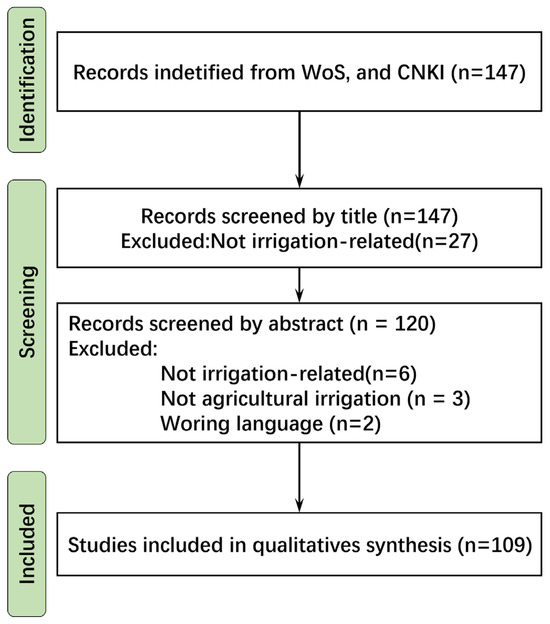
Figure 1.
Schematic flow diagram detailing the literature search, handing, and screening phases. (Original figure by the authors.).
3. Results and Discussions
3.1. Direct-Acting Pressure Regulator
The direct-acting pressure regulators are widely installed at the submain and lateral inlet of micro-irrigation systems [57,58,59,60] and upstream of “Low Energy Precision Application (LEPA)” nozzles [38,61]. Installing a pressure regulator at the inlet of a drip tape resolves the issue of low system uniformity caused by varying topography and hydraulic losses associated with non-pressure-compensated emitters [62,63,64,65]. This also avoids the inconvenience of thin-wall drip tape bursting under high inlet pressures and optimizes the hydraulic design of the system. Unlike methods involving reducing irrigation pressure and control area, this approach enables the practical and feasible large-scale adoption of precision drip irrigation systems with low energy consumption [66,67,68,69].
Most modern pressure regulators feature an integrated spring mechanism. These products are generally categorized into small-flow and large-flow types based on their flow rates. The schematic of a typical direct-acting pressure regulator is shown in Figure 2. When the pressure regulator is not in operation, the regulating plunger is held in its initial position by the force of the spring and a groove with the flow orifice in its maximum state. Once the pressure regulator starts operating, the regulating plunger is surrounded by flowing water and sealed by the O-ring to prevent water ingress. When the inlet pressure is below the threshold pressure, the regulating plunger remains stationary with the resultant force acting axially downstream; at this stage, the outlet pressure increases as the inlet pressure rises (see Figure 3). As soon as the inlet pressure surpasses the threshold pressure, the force exerted by the water pressure on the regulating plunger overcomes the preloading force of the spring and friction, pushing the plunger forward. During this process, additional water pressure loss occurs due to the opening of the flow orifice in response to the upward movement of the regulating plunger. The regulating plunger may move axially back and forth several times until a dynamic balance is achieved; consequently, higher inlet pressures are regulated to lower outlet pressures.
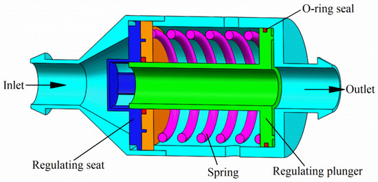
Figure 2.
Schematic cross-section of the direct-acting pressure regulator. (Original figure by the authors.).
The stable outlet pressure, regulation range, and outlet pressure accuracy of the pressure regulator are the more concerned performance indicators, determined based on preset pressure, initial regulation pressure, and tolerance, respectively. A typical input–output pressure relationship is depicted in Figure 3. Preset pressure refers to the stable output pressure of a regulator. Relative research has revealed a linear relationship between the preset pressure and the preload of the spring [66,70]. Modifying the dimensions of the spring can yield varying outlet preset pressures and pressure-regulating characteristics [71]. Tian analyzed the main structural parameters of the pressure regulator affecting the preset pressure through orthogonal experiments [72]. The results showed that the spring stiffness coefficient K (N/mm), initial compression length of the spring L (mm), the gap between the regulating components and the inlet basket plug b (mm), and the ratio of the outlet cross-sectional area to the inlet cross-sectional area of the adjusting components S2/S1 had significant effects on the preset pressure Ps (MPa). By regression analysis, the relationship between the preset pressure and these structural parameters was obtained [73]:
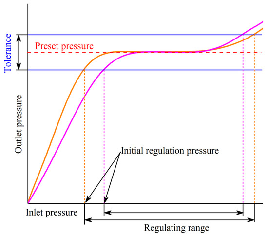

Figure 3.
Schematic of regulating performance curve (original figure by the authors). The initial regulating pressure is the minimum inlet pressure necessary to achieve the preset pressure that falls within the acceptable tolerance range. Some scholars define the preset pressure as the inlet pressure value when the ratio of the outlet pressure variation to the inlet pressure increment is less than 5%. The initial regulating pressure can be achieved by employing segmented linear regression, which divides the performance curve of the pressure regulator into start-up and regulation stages [74]. In an ideal scenario, the initial regulation pressure should be equal to the preset pressure. Yan conducted experiments comparing the pressure-regulating characteristics of seven pressure regulators with different preset pressures. The study indicated that the initial regulating pressure of the pressure regulator was greater than the preset pressure, and the difference between them increases as the preset pressure rises [75]. Li applied a fluid–structure interaction numerical method to calculate the initial regulating pressure values of the same structure pressure regulator under different preset pressures. The study demonstrated that the initial regulating pressure Pi had a linear relationship with the preset pressure Ps.
In the equation, a and b are constants related to the initial stress and stiffness coefficient of the spring. Combining Equation (1), it can be observed that the initial regulating pressure is also related to other structural parameters of the pressure regulator. A lower initial regulating pressure means that the regulator has a wider regulation range. In order to expand the pressure regulation range, researchers have proposed optimization models that simultaneously consider preset pressure and the initial regulating pressure, thus facilitating the attainment of optimal structural parameters for the pressure regulator [76].
The tolerance refers to the allowable deviation between the actual outlet pressure and the preset pressure. Under diverse flow conditions, the output pressure is affected not only by the pressure regulator structure but also by the flow rate. This dual influence can lead to deviations in outlet pressure [77]. Increasing flow can alleviate the hysteresis effect of the regulator, leading to lower outlet pressure than the preset pressure when flow is excessive, and higher outlet pressure when flow is insufficient. Fluctuations in flow sometimes result in significant deviations in outlet pressure [76,78]. Mohr analyzed the impact of different flow rates on the performance of pressure regulators. The results indicated that operating the center pivot irrigation machine at a moderate flow rate of 0.3~0.4 L/s achieved optimal performance [75]. Korven and D elucidated the hysteresis or lag phenomenon inherent in pressure regulators. This phenomenon manifests as non-coincident booster and pressure reduction performance curves, wherein outlet pressure during boosting exceeds that during pressure reduction under identical inlet pressure conditions. Such behavior predominantly arises from friction resulting from the relative movement among internal components of the pressure regulator, including O-ring seals [79,80]. Wang investigated pressure regulators using O-ring seals with different inner diameters and varying amounts of lubricants [81]. The study demonstrated the frictional force of O-rings, acting as a retarding force, accelerates the motion components to achieve dynamic equilibrium faster, thereby stabilizing the outlet pressure of the pressure regulator more rapidly. However, higher friction leads to larger fluctuations in the regulation performance curve, with the amplitude of fluctuations increasing with flow rate. Pressure regulators with higher friction have a narrower applicable flow rate range within a certain limit of fluctuations.
Current research on pressure regulator performance has made progress, yet several challenges remain unresolved. Firstly, the relationship between preset pressure and initial regulation pressure—though some studies suggest a linear correlation—warrants deeper investigation to discern underlying mechanisms and their variations under different conditions. Secondly, the impact of flow rate on pressure regulator performance remains inadequately understood, particularly regarding dynamic response and stability under varying flow conditions. Additionally, the influence of internal structural friction on performance requires further exploration, especially concerning variations in lubricant quantity and inner diameter. Hence, it is determined that future research should delve deeper into these issues to optimize pressure regulator design, enhance performance, and meet evolving engineering application demands.
3.2. Diaphragm Pressure Reducing Valves
Agricultural applications demand reliable valves that can endure harsh conditions like high pressure, corrosive media, and particulate impurities. Diaphragm valves have emerged as a favorable choice over piston valves due to their simpler design, ease of maintenance, and superior adaptation to challenging environments, offering an extended lifespan [82]. Under the same overflow volume, the diaphragm valve is smaller than the plunger valve. In the realm of large-scale agricultural production, cost-effectiveness plays a crucial role. Diaphragm valve configurations, known for their uncomplicated structure that often eliminates the need for intricate components or precise machining, contribute to reduced manufacturing and maintenance expenses [83]. Moreover, diaphragm valves equipped with pilot valve systems present enhanced flexibility compared to direct-acting control mechanisms. The utilization of pilot valves enables precise regulation of the valve’s opening and closing speed, catering more accurately to various agricultural operational requirements such as irrigation and fertilization [78]. Furthermore, the adaptability of pilot valves to operate within a broader pressure range is essential for meeting the diverse needs of agricultural applications. This capability ensures optimal performance and reliability in scenarios where varying pressure levels are encountered. Through the integration of these features, diaphragm valves with pilot valve systems have become instrumental in enhancing the efficiency and effectiveness of agricultural processes by offering robustness, cost-effectiveness, flexibility, and precise control capabilities. Therefore, agricultural irrigation companies have introduced a variety of diaphragm valves.
According to the structure of the diaphragm valve, it can be divided into “direct-flow diaphragm valve” and “weir diaphragm valve” [84] (see Figure 4). Direct-flow diaphragm valves feature valve designs that reduce fluid turbulence and head loss through the valve by tilting the main valve body, thereby avoiding vertical flow from inlet to outlet. A weir diaphragm valve is directly sealed; it has an elastic diaphragm; both as an actuator but also as a sealing element, this valve structure is simple, making it more convenient in terms of maintenance. In the analysis of a hydraulically operated diaphragm valve, Monserrat tested a diaphragm-actuated valve that relies on an elastic diaphragm to control the opening fraction based on pipeline pressure [85]. Zhou proposed a computational fluid dynamics method to evaluate the valve flow coefficient accurately, crucial for understanding the valve’s energy efficiency [84], which emphasized the significance of determining the pressure losses induced by the valve to calculate the flow coefficient precisely. Mehra explored the behavior of a three-way pilot-operated diaphragm valve and observed chaotic behavior with sudden variations in upstream pressure [86], which could relate to the unsteady valve behavior noted after pressure drops in Monserrat et al.’s study. Doghri evaluated the regulation response of pilot-operated diaphragm PRVs in water distribution systems and discussed the impact of valve sensitivity to pressure settings [87]. Gao studied the impact of elastic diaphragm parameters on automatic flushing valve performance [88], which aligns with the use of an elastic diaphragm in Monserrat et al.’s work. The study by Thierheimer focused on the performance of diaphragm elastic elements in ABS, contributing insights into the behavior of diaphragm-based valves [89].
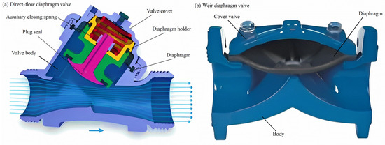
Figure 4.
Schematic cross-section of the diaphragm valves [84]: (a) Direct-flow diaphragm valve; (b) Weir diaphragm valve.
The aforementioned studies predominantly center on the direct-flow diaphragm valve, primarily oriented towards industrial applications. However, research pertaining to weir diaphragm valves remains relatively limited. Weir diaphragm valves, distinguished by their straightforward design and reduced failure rates, exhibit particular suitability for pressure reduction systems where precise pressure control is unnecessary, especially in scenarios involving media with higher impurity levels. The diaphragm, serving as the pivotal component of weir diaphragm valves, influences their pressure reduction characteristics directly through its structure and material composition, necessitating further exploration in this area.
3.3. Bio-Inspired Pressure Compensation
Zimoch et al. [90,91] proposed a low-cost pressure-compensated valve inspired by the nonlinear deformation of thin-walled biological tubes, such as human bronchi. When the transmural pressure becomes negative (i.e., external pressure exceeds internal pressure), the elastic tube collapses, limiting flow despite increasing pressure differentials. This phenomenon—analogous to flow regulation in biological systems—was applied to develop a passive pressure-compensating mechanism (Figure 5). The relationship between cross-sectional area and transmural pressure in elastic tubes is commonly referred to as the tube law and is determined experimentally. The relationship between the applied pressure difference ∆P (Pa) and the flow rate Q (m3/s) through the tube is described [92] as follows:
where n is an empirical factor between 1 and 2, and Kp represents the bending stiffness of the tube’s walls, kg·m2/s2. L is the length of the duct, m; D is its hydraulic diameter, m; f is the Moody friction factor; and ρ is the density of the fluid, kg/m3.
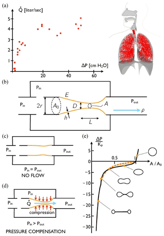
Figure 5.
Bio-inspired pressure compensation [93]. (a) Flow rate–pressure relationship in the human airway. (b) Simple model of the human airway: a flexible tube (orange) fixed on two rigid supports (black) and placed in a chamber open to the inlet pressure. (c) Relaxed configuration of the valve. (d) Pressure compensation configuration. (e) The variation in cross-sectional area of a flexible cylinder with transmural pressure.
Based on this principle, a prototype valve was fabricated using silicone rubber (modulus ≈ 1.0 MPa), consisting of a flexible inner tube supported by a perforated rigid frame to allow for controlled deformation under pressure. As shown in Figure 6, the valve design is simple and manufacturable. Performance tests demonstrated effective pressure compensation, with a stable flow rate of ~17 L/h and an activation pressure of ~0.1 bar, making it suitable for low-pressure drip irrigation [93].
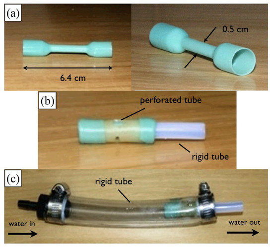
Figure 6.
Construction of a prototype [94]. (a) A flexible tube, manufactured from silicone rubber by dip-coating. (b) Subassembly showing the flexible tube supported on a perforated tube with a rigid tube press/fit on one end. (c) The complete valve assembly, with the subassembly from (b) shown inside a large-diameter tube section.
While this biomimetic valve offers advantages such as simplicity, low cost, and self-regulation, it also exhibits limitations. Flow precision may vary due to material fatigue or geometric inconsistency. Additionally, its long-term durability is affected by environmental exposure and material aging. The valve is most applicable in low-flow micro-irrigation systems but may be unsuitable for applications requiring high flow stability or broad pressure ranges.
3.4. Controllable Butterfly Valve
Kincaid [73] proposed a lightweight and low-cost butterfly valve system capable of automatically regulating downstream pressure in irrigation pipelines. The design (Figure 7) features a butterfly disc controlled by a cylinder–spring system that adjusts the disc’s aperture according to upstream pressure. When the upstream pressure increases beyond a preset value, the spring-loaded mechanism closes the valve to maintain stable downstream pressure. The relationship between the preset pressure P2 (kPa) and the structural parameters in the pressure regulation system is established [93] as follows:
Here, Fs0 is the initial external spring force (N); ks is the external spring stiffness (N/mm); Ls0 is the initial length of the external spring (mm); Ls is the length of the external spring (mm), ; Fc0 is the initial cylinder spring force (N); kc is the cylinder spring stiffness (N/mm); Lc0 is the initial length of the cylinder spring; Lc is the length of the cylinder spring (mm), ; C is the air cylinder piston area (mm2); Rs is the external spring attachment radius (mm); Rc is the cylinder spring attachment radius (mm); B is the base length between the air cylinder fixed pivot and the butterfly shaft (mm). Sr is the dimensionless parameter defined by
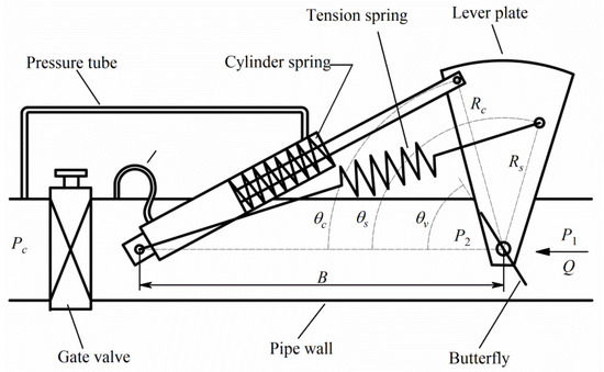
Figure 7.
Schematic of butterfly valve, control, and design parameters. (Original figure by the authors).
The valve performance was precisely evaluated through experimental measurements. The obtained upper and lower response curves, as shown in Figure 8, illustrate the behavior of the control system under fluctuations in upstream pressure. The difference between the two curves reflects the hysteresis caused by friction in the valve shaft or cylinder. Notably, the upper response curve appears flatter than expected, primarily due to the influence of friction and slight unbalanced hydrodynamic forces acting on the butterfly disk at certain angles.
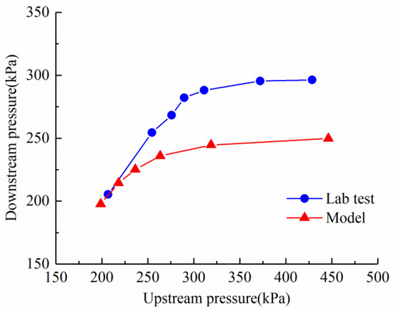
Figure 8.
Model-predicted and laboratory-measured response. (Original figure by the authors.).
Experimental results indicated that there is a certain deviation between the response curve of the valve and the theoretical model, partly due to friction and inertia effects of the valve shaft or cylinder. This may reduce the control precision of the system, lacking further analysis. Despite the low manufacturing cost of the valve, maintenance and adjustment of the valve system may be relatively complex, especially when changes in spring tension or adjustments to other parameters are required, which may necessitate intervention by technical personnel and thus require further simplification. Additionally, the valve lacks an external isolation device, which may result in field particles becoming lodged between the outer spring or other devices, thereby affecting the normal operation of the valve.
3.5. Pressure-Compensating Emitter
Pressure-compensating emitters, while operating at the terminal end of irrigation pipelines, play a critical role in maintaining outlet pressure and uniform discharge in low-pressure systems. As such, they form an integral part of the broader pressure regulation strategy [73,95]. It can be classified into non-pressure-compensating (NPC) emitters and pressure-compensating (PC) emitters, distinguished by their energy consumption principles and structural characteristics [96,97]. NPC emitters exhibit sensitivity to fluctuations in water pressure and terrain irregularities, potentially compromising irrigation uniformity and the efficacy of water and fertilizer application in drip irrigation systems. Conversely, PC emitters demonstrate a robust capability to sustain a nearly constant flow rate over a wide spectrum of water pressures. This attribute is crucial for ensuring consistent irrigation in scenarios characterized by pronounced terrain variations, fluctuating system operating pressures, or extensive drip tape deployment [98,99,100]. PC emitters can be further categorized into flat emitter, cylindrical emitters, and button emitter, according to the body shape of the PC emitters. Despite the diversity in shapes of various PC emitters, they share a similar operational mechanism, characterized by the incorporation of labyrinthine channels and pressure-compensating chambers in their design. The physical models of PC emitters are illustrated in Figure 9.
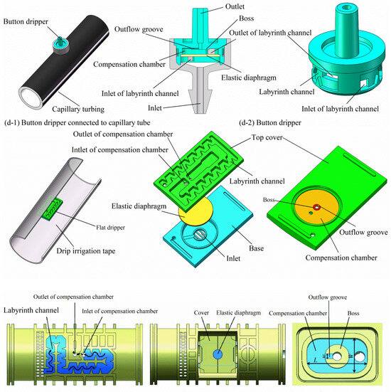
Figure 9.
Physical models of pressure-compensating emitters. (Original figure by the authors.).
In PC emitters, the ingress high-pressure water from the drip irrigation tube or tap is initially subjected to energy reduction through a labyrinthine flow channel. Subsequently, it undergoes secondary energy dissipation within the pressure-compensating chamber. This sequential, dual-stage approach effectively stabilizes the outlet pressure to a relatively constant value, ensuring uniformity in the flow rates from emitters positioned along various branch lengths and at disparate elevations, a crucial factor in maintaining consistent irrigation performance. Related studies indicate that the first energy dissipation efficiency is determined by the shape and size of the labyrinth channel. The rectangular, trapezoidal, and triangular labyrinth channels are extensively investigated in a prior study. The research shows that triangular channels have a stronger energy dissipation capacity than square and trapezoidal channels [101]. In recent research, some innovative flow channel structures have been proposed to enhance the hydraulic performance of drip irrigation emitters. These include a pit drip irrigation emitter inspired by the pit structure in bionic plant water transport tracheid [102], a perforated emitter utilizing the structure of scalar form perforation plates in plant xylem vessels [103], and various two-way mixed flow emitter prototypes [104]. Additionally, 13 M-type fractal flow paths, designed with diverse geometric parameters based on fractal theory, were also developed and examined [105]. The design and size of the flow channel unit are critical factors affecting internal flow dynamics. While these investigations offer novel insights into the design and enhancement of flow channel structures for irrigation emitters, their primary focus has been on velocity field and flow index analysis. However, there is a notable gap in research regarding the relationship between hydraulic performance and the structure of these new flow channel emitters. Specifically, detailed analysis of internal flow properties, such as turbulent kinetic energy and swirl characteristics, has not been comprehensively addressed in these studies.
PC emitters regulate the outflow cross-sectional area by deforming the elastic diaphragm, which is determined by the pressure difference between the inlet and outlet, thereby compensating for the effects of pressure changes on flow rate. This is the secondary energy dissipation process. Similar to direct-acting pressure regulators, the minimum compensating pressure and flow fluctuation exponent are crucial performance indicators for evaluating PC emitters. The corresponding studies have already revealed several key factors that influence the performance of PC emitters, including the height of the compensation chamber, the depth and width of the outflow groove, as well as the material, thickness, and hardness of the elastic diaphragm [106,107]. Recent research efforts have explored how these factors impact the minimum compensating pressure and flow fluctuation exponent of PC emitters through experiments and simulation analysis, which is essential for achieving efficient and water-saving irrigation. For instance, adjustments to the size and shape of the compensation chamber can significantly improve the emitter response time and flow control accuracy [108,109]. Furthermore, some studies have employed advanced algorithms like genetic algorithms to optimize the design of PC emitters, aiming to reduce both the minimum compensating pressure and flow fluctuation exponent [110]. Despite making significant progress, research on PC emitters still faces several challenges. One of them is finding ways to reduce manufacturing costs and complexity while maintaining high flow rate accuracy. Moreover, most existing studies have focused on the impact of individual factors, while research on the interactions and combined effects of multiple factors is relatively limited. Therefore, future research needs to pay more attention to how these factors interact and how comprehensive design approaches can enhance the overall performance and reliability of PC emitters.
3.6. Pump as Turbine Instead of Pressure-Reducing Valve
Pressure-reducing valves dissipate pressure energy, adding localized head loss to irrigation networks. This contradicts contemporary principles of resource-efficient practice. The dissipated pressure energy could be utilized to drive a turbine coupled with a generator, producing electricity and upholding the pressure reduction commitment within the sector. In this context, pump-as-turbine (PAT) devices represent a novel solution for pressure regulation in irrigation pipeline systems, particularly in scenarios where traditional PRVs result in energy loss. While primarily applied for energy recovery, PATs serve a dual function by ensuring downstream pressure control through hydraulic resistance and therefore can be considered part of the broader pressure regulation framework. The electricity generated can be used to supply solenoid valves and sensors in the irrigation network. Traditional hydraulic turbines designed specifically for converting throttling energy typically have a power output exceeding 100 kW [111]. Due to the low power found at the point in the water distribution network where there is a need to dissipate pressure, the use of conventional turbines is not feasible [112]. PAT emerges as a pivotal player, operating by utilizing conventional pumps in reverse mode, which offers a pragmatic solution for harnessing energy efficiently in scenarios where modest power outputs are required, as shown in Figure 10. But PAT installations face significant challenges that impede their advancement. A notable drawback of PAT installations is manufacturers’ failure to furnish turbine mode characteristics. These characteristics are crucial for precisely calculating energy production and determining the payback period before installation. This absence of essential information necessitates the development of predictive methods by researchers seeking to anticipate PAT performance. A second primary limitation stems from the absence of internal control mechanisms, such as guide vanes found in Francis turbines. This deficiency means that the operational curve of a PAT cannot be dynamically adjusted during use to align with fluctuating flow rates and head conditions. Consequently, efficiency sharply declines when operating away from its best efficiency point (BEP), particularly under part-load conditions.
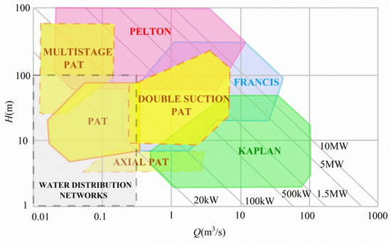
Figure 10.
Types of hydraulic turbines and PAT (multistage, single-suction, double-suction, and axial type) in their application area Q-H for micro-hydropower. (Original figure by the authors.).
In order to address the second challenge, researchers have proposed several control methods. One such strategy, hydraulic regulation (HR), entails the incorporation of two PRVs in series and parallel with the PAT to divert surplus flow or alleviate overpressure when the flow exceeds the PAT operational boundaries [113], as shown in Figure 11a. The back pressure (BP) means that the head value downstream of the equipment is specified as a constant value, primarily to enable the downstream sprinkler or dripper to run at the rated operating pressure. The upstream pressure Hu depends on the discharge Qd. Therefore, the available pressure ΔHd utilized by the PAT varies with the number of irrigators and the operating conditions, being ΔHd = Hu-BP. When no regulation is provided, the PAT works according to its characteristic curve ∆Ht = ∆Ht(Qd), and the ΔHd may not equal to ∆Ht(Qd). In HR, when Qd is low, the available head may exceed ΔHt due to low head loss in the pipeline and high Hu. In this case, the series valve can dissipate the remaining head ΔHv to achieve the BP value. Conversely, when Qd is high, ΔHt may be greater than ΔHd, in which case a certain amount of discharge Qb can be bypassed through the parallel valve to reduce the values of Qt and ΔHt, as depicted in Figure 11b. Another approach, electrical regulation (ER), incorporates a variable frequency drive to govern the PAT rotational speed [114], as shown in Figure 11c. If the ER is used, the rotational speed can be adjusted to modify the characteristic curve of the equipment and make ∆Ht equal to ∆Hd, as depicted in Figure 11d. However, achieving the desired downstream pressure has proven problematic, and operational points often deviate substantially from the best efficiency point, resulting in inferior overall efficiency compared to HR. Research efforts have explored the coupling of HR and ER, referred to as hydraulic and electrical regulation (HER) [115,116], as shown in Figure 11e. This HER approach has exhibited potential in enhancing the overall efficiency of PAT installations, offering a promising solution to mitigate the efficiency losses associated with operating conditions far from the best efficiency point.
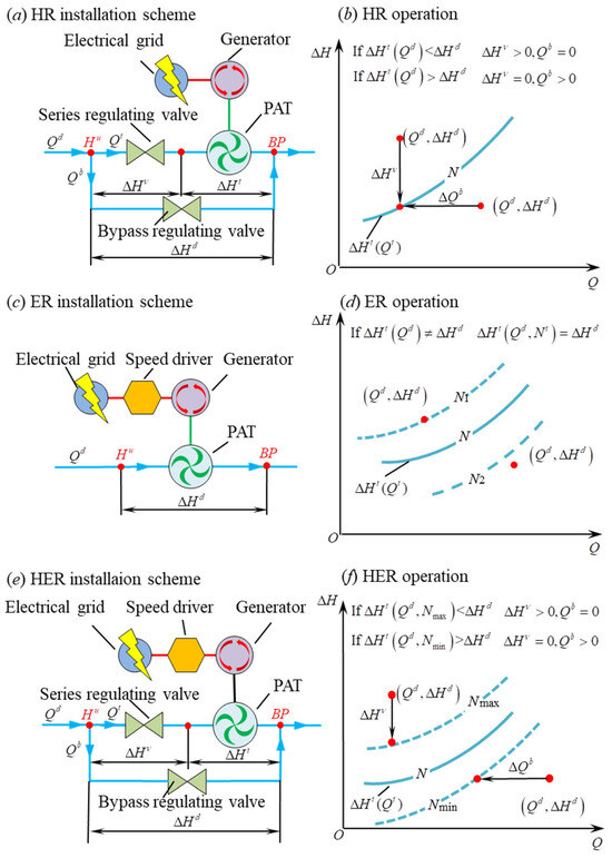
Figure 11.
Installation scheme and operation of a PAT in a water distribution network: (a) HR installation scheme; (b) HR operation; (c) ER installation scheme; (d) ER operation; (e) HER installation scheme; (f) HER operation. (Original figure by the authors.).
In a water distribution network, the strategic deployment of PRV and PAT plays a crucial role in mitigating excessive pressure within the pipeline system, thereby ensuring the maintenance of pressure equilibrium across the entire network. Research efforts have been directed towards optimizing the placement and control of PRV and PAT in domestic and industrial water distribution networks. Various optimization techniques, including linear programming, nonlinear programming, monolith integrated combinatorial nonlinear programming, mathematical programming with complementary constraints, and genetic algorithms, have been applied for this purpose [117]. Researchers have addressed the dynamic nature of PAT flow conditions during the day by employing particle swarm optimization (PSO) along with full pump curves to identify the optimal installation locations for PAT [118]. Furthermore, studies have extended to optimizing the settings of PRV and PAT to control pressure and reduce leakage. An optimization–simulation approach using PSO and hydraulic simulation software has been used to find optimal PRV settings, resulting in significant reductions in pressure and leakage [119]. Additionally, the performance of PAT has been evaluated under different scenarios, considering both constant and variable-speed PAT. It was found that PAT performs well during periods of peak network demand, generating power while maintaining pressure control. However, its performance diminishes during periods of minimal demand, leading to pressure deviations at critical junctions [116]. Lastly, efforts have been made to select suitable PAT installations for specific locations within a city and predict their characteristic curves to enhance their effectiveness in water distribution systems [120].
Traditional pressure-regulating devices consume excess water kinetic energy by changing the flow area, but PAT converts excess kinetic energy in the pipeline into electric energy for use or storage, which is sustainable. However, the operation and maintenance cost of the device is relatively high, and it is mainly used in factories and urban pipe networks. In a hilly irrigation system, a reasonable installation plan and location should be selected considering cost and sustainability. Secondly, the device is mainly installed in the main road or branch road with large flow, and there are fewer small PAT devices that can replace the upstream pressure compensation regulator and pressure compensator of the nozzle to adjust the pressure of the small flow pipeline. Although this part of energy is dispersed, its proportion in the system energy consumption cannot be ignored. And how to recycle and use this part of dispersed energy is still a problem to be considered.
3.7. Discussion
The comparative analysis of pressure regulation technologies in agricultural irrigation systems, as presented in Table 2, clearly demonstrates the unique advantages and limitations of each technical solution.

Table 2.
Comparative analysis of pressure regulation technologies in agricultural irrigation systems.
PRVs are highly regarded for their low cost and rapid response, but their limited regulation range and susceptibility to pressure oscillations remain significant concerns. Research by Zhang et al. [79] indicates that optimizing spring parameters can partially address these issues, though challenges such as initial pressure overshoot persist. Further studies by Wang et al. [85] highlight that friction from O-ring seals significantly impacts performance stability.
Pilot-operated pressure regulators deliver excellent accuracy and stability under high-flow conditions, but their complex structure and sensitivity to impurities limit their applicability. These findings are supported by Monserrat et al. [88], while Doghri et al. [91] additionally note that pilot valve systems require frequent calibration to maintain pressure settings.
Diaphragm valves are recognized for their superior corrosion resistance and simple design, yet material aging issues under high-flow conditions constrain their performance. Zhou et al. [89] emphasize the importance of material optimization in this regard.
Biomimetic self-compensating valves, inspired by biological systems, provide a low-cost solution for low-pressure micro-irrigation but suffer from material degradation and dimensional instability, as noted by Zimoch et al. [93]. These valves’ limited accuracy and environmental sensitivity underscore the need for improved manufacturing precision and durable materials. Follow-up studies by Shamshery et al. [113] have explored advanced silicone composites to enhance durability while maintaining the valves’ pressure-compensating properties.
Controllable butterfly valves, despite their light weight and cost-effectiveness, exhibit significant lag and friction-related inefficiencies, as demonstrated by Kincaid [73]. Their manual adjustment requirements and susceptibility to blockage further reduce their appeal. Recent field trials by Ella et al. [61] showed that automated tensioning systems could reduce hysteresis effects, suggesting potential for improvement.
Pressure-compensating emitters effectively address pressure fluctuations caused by elevation differences. Wei et al. [55] stress the need for optimized structural design, while Chen et al. [77] investigate compensation chamber geometry and Li et al. [99] explore micro/nano-aeration technology, providing new insights to address these challenges.
PAT systems achieve sustainable development through energy recovery, though their narrow high-efficiency operating range, as noted by Carravetta et al. [117], limits their widespread adoption.
4. Conclusions
Through a comparative analysis of various pressure regulation technologies in agricultural irrigation systems, the following comprehensive conclusions can be drawn: Different pressure regulation technologies each possess unique characteristics, and their practical application effectiveness must be selected based on specific irrigation requirements and environmental conditions. Direct-acting pressure regulators offer advantages of simple structure and rapid response, but have limited regulation range; pilot-operated regulators provide high control precision, yet demand strict water quality standards and complex maintenance; diaphragm valves and biomimetic valves demonstrate outstanding corrosion resistance and cost-effectiveness, though material durability still requires improvement; pressure-compensating emitters can effectively adapt to terrain variations, but feature relatively complex structural designs; turbine pump systems show promising potential in energy recovery, but their operational efficiency is significantly influenced by working conditions. Future research should focus on three key areas: development of new composite materials, integration of intelligent control technologies, and multi-technology collaborative optimization, aiming to enhance equipment reliability and adaptability to meet diverse irrigation needs. These technological innovations will contribute to building more efficient and sustainable agricultural irrigation systems, thereby providing effective solutions to address global water scarcity challenges.
Author Contributions
Conceptualization, F.Y. and H.L.; methodology, Y.J.; formal analysis, F.Y.; investigation, F.Y.; writing—original draft preparation, F.Y.; writing—review and editing, H.L. and Y.J.; supervision, H.L.; project administration, Y.J.; funding acquisition, H.L., Y.J. and F.Y. All authors have read and agreed to the published version of the manuscript.
Funding
This work was supported by the National Key Research and Development Project of China (2023YFD1900703), Jiangsu Provincial Key Research and Development Program (BE2021340) and Postgraduate Research & Practice Innovation Program of Jiangsu Province (KYCX23_3704).
Institutional Review Board Statement
Not applicable.
Data Availability Statement
Not applicable. No new data were created or analyzed in this study.
Conflicts of Interest
The authors declare no conflict of interest.
References
- Marangon, F.; Troiano, S.; Visintin, F. The Economic Value of Olive Plantation in Rural Areas: A Study on a Hill Region Between Italy and Slovenia. In Proceedings of the 12th Congress of the European Association of Agricultural Economists (EAAE), Parma, Italy, 26–29 August 2008. [Google Scholar]
- Daniel Kipruto, T.; Clement Cheruiyot, T.; Lydia, J. Analysis of Technical Efficiency of Small Scale Tea Production in Nandi Hills – Nandi County: A Data Envelopment Analysis Approach. Int. J. Res. Innov. Soc. Sci. 2020, 4, 149–163. [Google Scholar]
- María Galindo-Uribe, D.; Mario Hoyos-Hoyos, J.; Isaacs-Cubides, P.; Corral-Gómez, N.; Urbina-Cardona, N. Classification and sensitivity of taxonomic and functional diversity indices of anurans in the Andean coffee cultural landscape. Ecol. Indic. 2022, 136, 108650. [Google Scholar] [CrossRef]
- Vernie, A.; Rafdinal, R.; Ifadatin, S. Inventory of Edible Fruit Species in The Tembawang Forest Semahung Hills Saham Village Landak Regency. Biol. Samudra 2023, 5, 47–59. [Google Scholar] [CrossRef]
- Hu, H.J.; Lu, Y.Z.; Hu, Y.G.; Ding, R.S. Evaluation of Two Surface Renewal Methods for Calculating the Sensible Heat Flux over a Tea Field Ecosystem in Hilly Terrain. Agronomy 2023, 13, 1302. [Google Scholar] [CrossRef]
- Kannan, V.; Raja Priya, P.; Tharkeshwari, K.; Mazumder, B.; Gayatri, P.; Neha, J. Assessment of water demand and potential water sources to face future water scarcity of hilly regions. AQUA-Water Infrastruct. Ecosyst. Soc. 2023, 72, 299–312. [Google Scholar] [CrossRef]
- Mali, S. Irrigation Water Management Practices for Improved Crop Production and Productivity in Eastern Plateau and Hill Region of India. Agric. Food e-Newsl. 2023, 5, 206–209. [Google Scholar]
- Darko, R.O.; Yuan, S.Q.; Hong, L.; Liu, J.P.; Yan, H.F. Irrigation, a productive tool for food security—A review. Acta Agric. Scand. Sect. B-Soil Plant Sci. 2016, 66, 191–206. [Google Scholar] [CrossRef]
- Sruthy, K.T.; Arjun, T.P. Water Requirement of Major Tuber Crops: A Review. Int. J. Environ. Clim. Change 2023, 13, 1482–1487. [Google Scholar] [CrossRef]
- Menzel, C. Plant water relations and irrigation. In Litchi and Longan: Botany, Production, and Uses; CABI Publishing: Wallingford, UK, 2005; pp. 183–207. [Google Scholar]
- Aiken, R.; Lamm, F.; AbouKheira, A. Water use of oilseed crops. In Proceedings of the 23rd Annual Central Plains Irrigation Conference, Burlington, CO, USA, 22–23 February 2011. [Google Scholar]
- Dietz, K.J.; Zörb, C.; Geilfus, C.M. Drought and crop yield. Plant Biol. 2021, 23, 881–893. [Google Scholar] [CrossRef]
- Iqbal, M.S.; Singh, A.K.; Ansari, M.I. Effect of Drought Stress on Crop Production. In New Frontiers in Stress Management for Durable Agriculture; Rakshit, A., Singh, H.B., Singh, A.K., Singh, U.S., Fraceto, L., Eds.; Springer: Singapore, 2020; pp. 35–47. [Google Scholar]
- Wang, X.W.; Cai, H.J.; Zheng, Z.; Yu, L.Y.; Wang, Z.S.; Li, L. Modelling root water uptake under deficit irrigation and rewetting in Northwest China. Agron. J. 2020, 112, 158–174. [Google Scholar] [CrossRef]
- Kumari, P.; Bara, A.; Kumar, M.; Job, M.; Rai, P. Crop water requirement and water use efficiency of cauliflower under mulching and drip irrigation in eastern Plateau hills region of Jharkhand. Progress. Hortic. 2020, 52, 81–87. [Google Scholar] [CrossRef]
- Steele, D.D.; Greenland, R.G.; Hatterman-Valenti, H.M. Furrow vs hill planting of sprinkler-irrigated russet burbank potatoes on coarse-textured soils. Am. J. Potato Res. 2006, 83, 249–257. [Google Scholar] [CrossRef]
- Chauhdary, J.N.; Li, H.; Jiang, Y.; Pan, X.W.; Hussain, Z.; Javaid, M.; Rizwan, M. Advances in Sprinkler Irrigation: A Review in the Context of Precision Irrigation for Crop Production. Agronomy 2024, 14, 47. [Google Scholar] [CrossRef]
- Darko, R.O.; Yuan, S.Q.; Liu, J.P.; Yan, H.F.; Zhu, X.Y. Overview of advances in improving uniformity and water use efficiency of sprinkler irrigation. Int. J. Agric. Biol. Eng. 2017, 10, 1–15. [Google Scholar] [CrossRef]
- Brouwer, C.; Prins, K.; Kay, M.; Heibloem, M. Irrigation water management: Irrigation methods. Train. Man. 1988, 9, 5–7. [Google Scholar]
- Wannapop, R.; Jearsiripongkul, T.; Jiamjiroch, K. Effect of elevation to accuracy in water pipeline network simulation. Eng. Appl. Sci. Res. 2016, 43, 454–458. [Google Scholar]
- Daccache, A.; Lamaddalena, N.; Fratino, U. Assessing Pressure Changes in an On-Demand Water Distribution System on Drip Irrigation Performance—Case Study in Italy. J. Irrig. Drain. Eng. 2010, 136, 261–270. [Google Scholar] [CrossRef]
- Wang, W.; Xu, R.; Wei, R.; Wang, W.; Hu, X. Effects of different pressures and laying lengths of micro-sprinkling hose irrigation on irrigation uniformity and yield of spring wheat. Agric. Water Manag. 2023, 288, 108495. [Google Scholar] [CrossRef]
- Bruckler, L.; Lafolie, F.; Ruy, S.; Granier, J.; Baudequin, D. Modelling the agricultural and environmental consequences of non-uniform irrigation on a maize crop. 1. Water balance and yield. Agronomie 2000, 20, 609–624. [Google Scholar] [CrossRef]
- Dechmi, F.; Playán, E.; Cavero, J.; Faci, J.; Martínez-Cob, A. Wind effects on solid set sprinkler irrigation depth and yield of maize (Zea mays). Irrig. Sci. 2003, 22, 67–77. [Google Scholar] [CrossRef]
- Stern, J.; Bresler, E. Nonuniform sprinkler irrigation and crop yield. Irrig. Sci. 1983, 4, 17–29. [Google Scholar] [CrossRef]
- Jiménez, M. La Distribución del Agua Bajo Riego por Aspersión Estacionario y su Influencia Sobre el Rendimiento del Cultivo de la Cebolla (Allium cepa L.). Doctoral Thesis, ETSIA, Universidad de Castilla-La Mancha, Albacete, Spain, 2008. [Google Scholar]
- Miao, Q.; Gonçalves, J.M.; Li, R.; Gonçalves, D.; Levita, T.; Shi, H. Assessment of Precise Land Levelling on Surface Irrigation Development. Impacts on Maize Water Productivity and Economics. Sustainability 2021, 13, 1191. [Google Scholar] [CrossRef]
- Bai, M.; Xu, D.; Li, Y.; Zhang, S.; Liu, S. Coupled impact of spatial variability of infiltration and microtopography on basin irrigation performances. Irrig. Sci. 2017, 35, 437–449. [Google Scholar] [CrossRef]
- Naresh, R.; Singh, S.; Misra, A.; Tomar, S.; Kumar, P.; Kumar, V.; Kumar, S. Evaluation of the laser leveled land leveling technology on crop yield and water use productivity in Western Uttar Pradesh. Afr. J. Agric. Res. 2014, 9, 473–478. [Google Scholar] [CrossRef]
- Zhang, Q.-q.; Luo, H.-b.; Yan, J.-m. Integrating biodiversity conservation into land consolidation in hilly areas—A case study in southwest China. Acta Ecol. Sin. 2012, 32, 274–278. [Google Scholar] [CrossRef]
- Jat, M.; Gathala, M.K.; Ladha, J.; Saharawat, Y.; Jat, A.; Kumar, V.; Sharma, S.; Kumar, V.; Gupta, R. Evaluation of precision land leveling and double zero-till systems in the rice–wheat rotation: Water use, productivity, profitability and soil physical properties. Soil Tillage Res. 2009, 105, 112–121. [Google Scholar] [CrossRef]
- Aquino, L.S.; Timm, L.C.; Reichardt, K.; Barbosa, E.P.; Parfitt, J.M.B.; Nebel, A.L.C.; Penning, L.H. State-space approach to evaluate effects of land levelling on the spatial relationships of soil properties of a lowland area. Soil Tillage Res. 2015, 145, 135–147. [Google Scholar] [CrossRef]
- Zhiliang, D. Initial Exploration of Pressure Reduction in Gravity Flow Pipeline System Pressure Reducing Tank. J. Water Resour. Water Eng. 1993, 4, 58–62. [Google Scholar]
- Dang, Z.; Tian, C. Research on Automatic Water Level Control Device for Self-Pressure Sprinkler Irrigation Pressure Reducing Tank. China Rural Water Hydropower 1994, 3, 33–35. [Google Scholar]
- Zhiliang, D. Determination of Available Volume of Pressure-Reduction Pool for Self-Pressure Sprinkler Irrigation. J. Xi’an Univ. Technol. 1999, 15, 66–68. [Google Scholar] [CrossRef]
- Zumin, R. The Planning-layout and Application of Sprinkler on Sloping Land. Mod. Agric. Sci. 2008, 15, 51–52. [Google Scholar]
- Pérez, R.; Martínez, F.; Vela, A. Cost reduction in irrigation networks by an efficient use of pressure reducing valves. In Pipeline Systems; Springer: Dordrecht, The Netherlands, 1992; pp. 43–57. [Google Scholar]
- Zhu, H.; Sorensen, R.; Butts, C.; Lamb, M.; Blankenship, P. A pressure regulating system for variable irrigation flow controls. Appl. Eng. Agric. 2002, 18, 533–540. [Google Scholar] [CrossRef]
- Pang, Y.; Li, H.; Tang, P.; Chen, C. Irrigation scheduling of pressurized irrigation networks for minimizing energy consumption. Irrig. Drain. 2023, 72, 268–283. [Google Scholar] [CrossRef]
- Fontana, N.; Giugni, M.; Glielmo, L.; Marini, G.; Zollo, R. Use of hydraulically operated PRVs for pressure regulation and power generation in water distribution networks. J. Water Resour. Plan. Manag. 2020, 146, 04020047. [Google Scholar] [CrossRef]
- Cho, N.-K.; Bansal, P.; Hurst, A.M. Investigating Structural Response of Pressure Reducing Valve of Supercritical Steam Generator System Under Cyclic Moments, Thermal Transient, and Pressure Loadings. In Proceedings of the International Conference on Nuclear Engineering, Virtually, 4–5 August 2020; p. V001T006A015. [Google Scholar]
- Chacón, M.C.; Díaz, J.A.R.; Morillo, J.G.; McNabola, A. Evaluation of the design and performance of a micro hydropower plant in a pressurised irrigation network: Real world application at farm-level in Southern Spain. Renew. Energy 2021, 169, 1106–1120. [Google Scholar] [CrossRef]
- Loganathan, S.; Esakkimuthu, P.; Srivatsan, M.; Anand, M. Performance Optimization of Single Cylinder Diesel Engine Oil Pump through PRV and Rotor System; SAE Technical Paper; SAE: Warrendale, PA, USA, 2015. [Google Scholar]
- Morselli, S.; Gessi, S.; Marani, P.; Martelli, M.; De Hieronymis, C.M.R. Dynamics of pilot operated pressure relief valves subjected to fast hydraulic transient. AIP Conf. Proc. 2019, 2191, 020116. [Google Scholar]
- McGlone, R.; Wichmann, H.; Fitzsimmons, M. Comparison of operating the Space Shuttle orbiter primary thruster with pilot operated versus direct acting valves. In Proceedings of the 22nd Joint Propulsion Conference, Huntsville, AL, USA, 16–18 June 1986; p. 1441. [Google Scholar]
- Chenxu, X.; Hongju, C.; Haohan, T.; Hong, G.; Qin, S.; Yunfeng, H.; Peng, J. Next Generation of Underwater Wet-Mate Electrical Connectors. In Proceedings of the 2023 IEEE International Conference on Electrical, Automation and Computer Engineering (ICEACE), Changchun, China, 29–31 December 2023; pp. 165–172. [Google Scholar]
- Nesbitt, B. Handbook of Valves and Actuators: Valves Manual International; Elsevier: Oxford, UK, 2011. [Google Scholar]
- Mitra, S.; Mathew, S.; Rajan, A.; Sajeev, P. Design of a Gas Filled Bellow Pogo Suppression Device for Launch Vehicles. Adv. Astronaut. Sci. Technol. 2021, 4, 27–37. [Google Scholar] [CrossRef]
- Fale, V.; Shelare, S.; Khope, P. State of the art of pressure regulators for industrial applications. AIP Conf. Proc. 2023, 2800, 020151. [Google Scholar]
- He, X.; Zhao, D.; Sun, X.; Zhu, B. Theoretical and experimental research on a three-way water hydraulic pressure reducing valve. J. Press. Vessel Technol. 2017, 139, 041601. [Google Scholar] [CrossRef]
- Meniconi, S.; Brunone, B.; Mazzetti, E.; Laucelli, D.B.; Borta, G. Hydraulic characterization and transient response of pressure reducing valves: Laboratory experiments. J. Hydroinform. 2017, 19, 798–810. [Google Scholar] [CrossRef]
- García-Todolí, S.; Iglesias-Rey, P.; Martínez-Solano, F. Experimental analysis of proportional pressure reducing valves for water distribution systems. In Proceedings of the World Environmental and Water Resources Congress 2017, Sacramento, CA, USA, 21–25 May 2017; pp. 637–647. [Google Scholar]
- Hős, C.; Champneys, A.; Paul, K.; McNeely, M. Dynamic behavior of direct spring loaded pressure relief valves in gas service: Model development, measurements and instability mechanisms. J. Loss Prev. Process Ind. 2014, 31, 70–81. [Google Scholar] [CrossRef]
- Jin, Z.-j.; Wei, L.; Chen, L.-l.; Qian, J.-y.; Zhang, M. Numerical simulation and structure improvement of double throttling in a high parameter pressure reducing valve. J. Zhejiang Univ. Sci. A 2013, 14, 137–146. [Google Scholar] [CrossRef][Green Version]
- Wei, L.; Zhu, G.; Qian, J.; Fei, Y.; Jin, Z. Numerical simulation of flow-induced noise in high pressure reducing valve. PLoS ONE 2015, 10, e0129050. [Google Scholar] [CrossRef] [PubMed]
- Hanaei, S.; Lakzian, E. Numerical and experimental investigation of the effect of the optimal usage of pump as turbine instead of pressure-reducing valves on leakage reduction by genetic algorithm. Energy Convers. Manag. 2022, 270, 116253. [Google Scholar] [CrossRef]
- Bhatnagar, P.; Srivastava, R. Gravity-fed drip irrigation system for hilly terraces of the northwest Himalayas. Irrig. Sci. 2003, 21, 151–157. [Google Scholar] [CrossRef]
- Kumar, M.; Kumar, N.; Singh, K.P.; Kumar, P.; Srinivas, K.; Srivastva, A.K. Integrating water harvesting and gravity-fed micro-irrigation system for efficient water management in terraced land for growing vegetables. Biosyst. Eng. 2009, 102, 106–113. [Google Scholar] [CrossRef]
- Lamaddalena, N.; Khila, S. Energy saving with variable speed pumps in on-demand irrigation systems. Irrig. Sci. 2012, 30, 157–166. [Google Scholar] [CrossRef]
- Uossef Gomrokchi, A. Dynamic Modeling of Variable Speed Pumps in Pressurized Irrigation System Considering Energy Consumption Analysis (Case Study: Ashrafieh Agro-Industry Irrigation System). Irrig. Drain. Struct. Eng. Res. 2017, 18, 143–160. [Google Scholar] [CrossRef]
- Ella, V.B.; Keller, J.; Reyes, M.R.; Yoder, R. A low-cost pressure regulator for improving the water distribution uniformity of a microtube-type drip irrigation system. Appl. Eng. Agric. 2013, 29, 343–349. [Google Scholar]
- Meniconi, S.; Brunone, B.; Mazzetti, E.; Laucelli, D.B.; Borta, G. Pressure reducing valve characterization for pipe system management. Procedia Eng. 2016, 162, 455–462. [Google Scholar] [CrossRef]
- Zhao, R.-H.; Zhang, Z.-H.; He, W.-Q.; Lou, Z.-K.; Ma, X.-Y. Synthetical Optimization of a Gravity-Driven Irrigation Pipeline Network System with Pressure-Regulating Facilities. Water 2019, 11, 1112. [Google Scholar] [CrossRef]
- Waller, P.; Yitayew, M. Irrigation and Drainage Engineering; Springer: Berlin/Heidelberg, Germany, 2015. [Google Scholar]
- Lianhao, L.; Xinyue, Z.; Xiaodong, Q.; Guiming, L. Analysis of the decrease of center pivot sprinkling system uniformity and its impact on maize yield. Int. J. Agric. Biol. Eng. 2016, 9, 108–119. [Google Scholar]
- Chirgwin, G.A.; Sutton, B. A low-cost, high-precision drip emitter suitable for low-pressure micro-irrigation systems. Irrig. Sci. 2019, 37, 725–735. [Google Scholar] [CrossRef]
- Mahesha, M.; Venkatachalapathy, K.; Tulasidas, T.; Rajashekharappa, K. Emitter sensitivity to operating pressure and uniform slopes. Environ. Ecol. 2006, 24, 17–19. [Google Scholar]
- Keshtgar, A.; Bhuiyan, M.A.; Jayasuriya, N. Design of drip irrigation system using microtubes for full emission uniformity. Irrig. Drain. 2013, 62, 613–623. [Google Scholar] [CrossRef]
- Nakayama, F.S.; Boman, B.J.; Pitts, D.J. 11. Maintenance. In Developments in Agricultural Engineering; Elsevier: Amsterdam, The Netherlands, 2007; Volume 13, pp. 389–430. [Google Scholar]
- Surendran, U.; Jayakumar, M.; Marimuthu, S. Low cost drip irrigation: Impact on sugarcane yield, water and energy saving in semiarid tropical agro ecosystem in India. Sci. Total Environ. 2016, 573, 1430–1440. [Google Scholar] [CrossRef]
- Ella, V.B.; Reyes, M.R.; Yoder, R. Effect of hydraulic head and slope on water distribution uniformity of a low-cost drip irrigation system. Appl. Eng. Agric. 2009, 25, 349–356. [Google Scholar] [CrossRef]
- Karlberg, L.; Rockström, J.; Annandale, J.G.; Steyn, J.M. Low-cost drip irrigation—A suitable technology for southern Africa?: An example with tomatoes using saline irrigation water. Agric. Water Manag. 2007, 89, 59–70. [Google Scholar] [CrossRef]
- Kincaid, D.C.; Romspert, D.G. Inexpensive Pressure Regulation for Irrigation Pipelines. Appl. Eng. Agric. 1996, 12, 203–207. [Google Scholar] [CrossRef]
- Li, L.; Niu, W. Influence of Spring on Pressure Regulating Effect of Micro-irrigation Pressure Regulator. J. Irrig. Drain. 2015, 34, 15–18+44. [Google Scholar] [CrossRef]
- Yan, H.J.; Yao, P.P.; Wang, M. Performance test and force analysis of pressure regulator used in irrigation system. J. Drain. Irrig. 2010, 6, 548–552. [Google Scholar]
- Tian, J.X.; Gong, S.H.; Li, G.Y.; Wang, J.D. Impacts of pressure regulator parameters on preset pressure in micro-irrigation system. Trans. CSAE 2005, 12, 48–51. [Google Scholar]
- Chen, X.; Wei, Z.; Wei, C.; He, K. Effect of compensation chamber structure on the hydraulic performance of pressure compensating drip emitters. Biosyst. Eng. 2022, 214, 107–121. [Google Scholar] [CrossRef]
- von Bemuth, R.D.; Baird, D. Characterizing Pressure Regulator Performance. Trans. ASAE 1990, 33, 145–150. [Google Scholar] [CrossRef]
- Zhang, C.; Li, G. Optimization of a direct-acting pressure regulator for irrigation systems based on CFD simulation and response surface methodology. Irrig. Sci. 2017, 35, 383–395. [Google Scholar] [CrossRef]
- Kincaid, D.C. Evaluation of Very Low Pressure Sprinkler Irrigation and Reservoir Tillage for Efficient Use of Water and Energy: Final Report; U.S. Department of Energy: Washington, DC, USA, 1987.
- Talamini Junior, M.V.; de Araujo, A.C.S.; de Camargo, A.A.-O.; Saretta, E.; Frizzone, J.A. Operational Characterization of Pressure Regulating Valves. Sci. World J. 2018, 2018, 1213638. [Google Scholar] [CrossRef]
- Mohr, D. Performance Characterisation of Pressure Regulation Devices Used in Broad-Acre Irrigation; University of Southern Queensland: Toowoomba, Australia, 2011. [Google Scholar]
- Korven, H.C.; Wilcox, J.C. An Evaluation of Flow and Pressure Regulators for Sprinkler Irrigation. Trans. ASAE 1966, 9, 516–519. [Google Scholar] [CrossRef]
- Mbiya, B.M.; Fester, V.G.; Slatter, P.T. Evaluating resistance coefficients of straight-through diaphragm control valves. Can. J. Chem. Eng. 2009, 87, 704–714. [Google Scholar] [CrossRef]
- Wang, X.; Li, G.; Zhang, C. Simulation analysis of the effects of friction on the performance of pressure regulator for drip tape. Comput. Electron. Agric. 2021, 184, 106130. [Google Scholar] [CrossRef]
- Ohlsson, P.-Å. Diaphragm valve development–challenging traditional thinking. Pharm. Eng. 2013, 33, 1–4. [Google Scholar]
- Heimann, A.; Meyer, N.; Liemberger, R. Tailoring the Specifications for Pressure Reducing Valves. In Proceedings of the 5th IWA Water Loss Reduction Specialist Conference, Cape Town, South Africa, 26–30 April 2009. [Google Scholar]
- Monserrat, J.; Rubio, A.; Cots, L. Diaphragm Valve Hydraulic Behavior Depending on Operating Pressure. J. Irrig. Drain. Eng. 2019, 145, 06019007. [Google Scholar] [CrossRef]
- Zhou, X.; Wang, Z.; Zhang, Y. A simple method for high-precision evaluation of valve flow coefficient by computational fluid dynamics simulation. Adv. Mech. Eng. 2017, 9, 1687814017713702. [Google Scholar] [CrossRef]
- Mehra, K. Literature Review on Design and Working of 3 Way Pilot Operated Diaphragm Controlled Hydraulic Control Valve. Int. J. Adv. Eng. Res. Sci. 2017, 4, 167–169. [Google Scholar] [CrossRef]
- Doghri, M.; Duchesne, S.; Poulin, A.; Villeneuve, J.-P. Regulation response of pilot operated diaphragm pressure reducing valves: Laboratory testing and impact on the performance of pressure control modes in water distribution systems. Can. J. Civ. Eng. 2021, 49, 636–643. [Google Scholar] [CrossRef]
- Thierheimer, W.; Alexandru, C.; Thierheimer, A.; Crauciuc, D. Performance of Diaphragm Elastic Elements in ABS. Appl. Mech. Mater. 2020, 896, 241–248. [Google Scholar] [CrossRef]
- Zimoch, P.J.; Tixier, E.; Joshi, A.; Hosoi, A.; Winter, A.G. Bio-Inspired, low-cost, self-regulating valves for drip irrigation in developing countries. In Proceedings of the International Design Engineering Technical Conferences and Computers and Information in Engineering Conference, Portland, OR, USA, 4–7 August 2013; p. V005T006A040. [Google Scholar]
- Afschrift, M.; Clément, J.; van de Woestijne, K. Maximum expiratory flows and effort independency in patients with airway obstruction. J. Appl. Physiol. 1974, 37, 566–569. [Google Scholar] [CrossRef]
- Wang, J.; Yang, T.; Wei, T.; Chen, R.; Yuan, S. Experimental determination of local head loss of non-coaxial emitters in thin-wall lay-flat polyethylene pipes. Biosyst. Eng. 2020, 190, 71–86. [Google Scholar] [CrossRef]
- Tang, P.; Li, H.; Issaka, Z.; Chen, C. Effect of manifold layout and fertilizer solution concentration on fertilization and flushing times and uniformity of drip irrigation systems. Agric. Water Manag. 2018, 200, 71–79. [Google Scholar] [CrossRef]
- Wang, J.; Chen, R. An improved finite element model for the hydraulic analysis of drip irrigation subunits considering local emitter head loss. Irrig. Sci. 2020, 38, 147–162. [Google Scholar] [CrossRef]
- Shabbir, A.; Mao, H.; Ullah, I.; Buttar, N.A.; Ajmal, M.; Lakhiar, I.A. Effects of Drip Irrigation Emitter Density with Various Irrigation Levels on Physiological Parameters, Root, Yield, and Quality of Cherry Tomato. Agronomy 2020, 10, 1685. [Google Scholar] [CrossRef]
- Li, H.; Li, P.; Li, J.; Jiang, Y.; Huang, X. Influence of micro/nano aeration on the diversity of the microbial community in drip irrigation to reduce emitter clogging. Biosyst. Eng. 2023, 235, 116–130. [Google Scholar] [CrossRef]
- Li, Y.-k.; Yang, P.-l.; Ren, S.-m.; Xu, T.-w. Hydraulic Characterizations of Tortuous Flow in Path Drip Irrigation Emitter. J. Hydrodyn. Ser. B 2006, 18, 449–457. [Google Scholar] [CrossRef]
- Perea, H.; Enciso, J.; Singh, V.; Dutta, D.; Lesikar, B. Statistical Analysis of Non-Pressure-Compensating and Pressure-Compensating Drip Emitters. J. Irrig. Drain. Eng. 2013, 139, 986–994. [Google Scholar] [CrossRef]
- Narain, J.; Winter, A.G. A Hybrid Computational and Analytical Model of Inline Drip Emitters. J. Mech. Des. 2018, 141, 071405. [Google Scholar] [CrossRef]
- Burt, C.; Feist, K. Low-Pressure Testing: Microirrigation Emitters; Irrigation Training & Research Center: San Luis Obispo, CA, USA, 2013. [Google Scholar]
- Oliver, M.M.H.; Hewa, G.A.; Pezzaniti, D. Thermal variation and pressure compensated emitters. Agric. Water Manag. 2016, 176, 29–39. [Google Scholar] [CrossRef]
- Wei, Q.; Shi, Y.; Dong, W.; Lu, G.; Huang, S. Study on hydraulic performance of drip emitters by computational fluid dynamics. Agric. Water Manag. 2006, 84, 130–136. [Google Scholar] [CrossRef]
- Xu, T.; Zhang, L. Influence and analysis of structure design and optimization on the performance of a pit drip irrigation emitter*. Irrig. Drain. 2020, 69, 633–645. [Google Scholar] [CrossRef]
- Xing, S.; Wang, Z.; Zhang, J.; Liu, N.; Zhou, B. Simulation and Verification of Hydraulic Performance and Energy Dissipation Mechanism of Perforated Drip Irrigation Emitters. Water 2021, 13, 171. [Google Scholar] [CrossRef]
- Guo, L.; Bai, D.; Zhou, W.; Wang, X. Evaluation of numerical simulation accuracy for two-ways mixed flow drip irrigation emitter based on CFD. Int. J. Heat Technol. 2017, 35, 384–392. [Google Scholar] [CrossRef]
- Zhangzhong, L.; Yang, P.; Li, Y.; Ren, S. Effects of Flow Path Geometrical Parameters on Flow Characteristics and Hydraulic Performance of Drip Irrigation Emitters. Irrig. Drain. 2016, 65, 426–438. [Google Scholar] [CrossRef]
- Wang, L.; Wei, Z.; Deng, T.; Tang, Y. The step-by-step CFD design method of pressure-compensating emitter. Trans. Chin. Soc. Agric. Eng. 2013, 28, 86–92. [Google Scholar]
- Wei, Z.; Ma, S.; Zhou, X.; Yuan, W. Influence factors on hydraulic performance of pressure-compensating emitter. Nongye Gongcheng Xuebao/Trans. Chin. Soc. Agric. Eng. 2015, 31, 19–25. [Google Scholar] [CrossRef]
- Shamshery, P.; Wang, R.-Q.; Tran, D.V.; Winter, A.G., V. Modeling the future of irrigation: A parametric description of pressure compensating drip irrigation emitter performance. PLoS ONE 2017, 12, e0175241. [Google Scholar] [CrossRef]
- Shamshery, P.; Winter, A.G., V. Shape and Form Optimization of On-Line Pressure-Compensating Drip Emitters to Achieve Lower Activation Pressure. J. Mech. Des. 2017, 140, 035001. [Google Scholar] [CrossRef]
- Morabito, A.; Hendrick, P. Pump as turbine applied to micro energy storage and smart water grids: A case study. Appl. Energy 2019, 241, 567–579. [Google Scholar] [CrossRef]
- Lima, G.M.; Junior, E.L.; Brentan, B.M. Selection of Pumps as Turbines Substituting Pressure Reducing Valves. Procedia Eng. 2017, 186, 676–683. [Google Scholar] [CrossRef]
- Stefanizzi, M.; Capurso, T.; Balacco, G.; Binetti, M.; Camporeale, S.M.; Torresi, M. Selection, control and techno-economic feasibility of Pumps as Turbines in Water Distribution Networks. Renew. Energy 2020, 162, 1292–1306. [Google Scholar] [CrossRef]
- Carravetta, A.; Del Giudice, G.; Fecarotta, O.; Ramos, H.M. Energy Production in Water Distribution Networks: A PAT Design Strategy. Water Resour. Manag. 2012, 26, 3947–3959. [Google Scholar] [CrossRef]
- Carravetta, A.; Del Giudice, G.; Fecarotta, O.; Ramos, H.M. PAT Design Strategy for Energy Recovery in Water Distribution Networks by Electrical Regulation. Energies 2013, 6, 411–424. [Google Scholar] [CrossRef]
- Fecarotta, O.; Ramos, H.; Derakhshan, S.; Del Giudice, G.; Carravetta, A. Fine Tuning a PAT Hydropower Plant in a Water Supply Network to Improve System Effectiveness. J. Water Resour. Plan. Manag. 2018, 144, 04018038. [Google Scholar] [CrossRef]
- Gupta, A.; Kulat, K.D.; Bokde, N.; Marathe, D. Leakage Reduction in Water Distribution Systems with Efficient Placement and Control of Pressure Reducing Valves Using Soft Computing Techniques. Eng. Technol. Appl. Sci. Res. 2017, 7, 1528–1534. [Google Scholar] [CrossRef]
Disclaimer/Publisher’s Note: The statements, opinions and data contained in all publications are solely those of the individual author(s) and contributor(s) and not of MDPI and/or the editor(s). MDPI and/or the editor(s) disclaim responsibility for any injury to people or property resulting from any ideas, methods, instructions or products referred to in the content. |
© 2025 by the authors. Licensee MDPI, Basel, Switzerland. This article is an open access article distributed under the terms and conditions of the Creative Commons Attribution (CC BY) license (https://creativecommons.org/licenses/by/4.0/).