Article

Research on Energy Distribution Strategy of Tandem Hybrid Tractor Based on the Pontryagin Minimum Principle

1
College of Engineering, Nanjing Agricultural University, Nanjing 210031, China
2
College of Locomotive Vehicle, Nanjing Institute of Railway Technology, Nanjing 210031, China
3
State Key Laboratory of Intelligent Agricultural Power Equipment, Luoyang 470139, China
*
Authors to whom correspondence should be addressed.
Agriculture 2024, 14(3), 440; https://doi.org/10.3390/agriculture14030440
Submission received: 25 January 2024 / Revised: 23 February 2024 / Accepted: 6 March 2024 / Published: 7 March 2024
(This article belongs to the Special Issue New Energy-Powered Agricultural Machinery and Equipment)

Abstract

:
In order to study the energy distribution of the tandem hybrid tractor and achieve optimal fuel economy under the whole operating condition, an energy distribution strategy based on PMP (Pontryagin minimum principle) is proposed. The performance parameters of the relevant power components are obtained by constructing the test bench of the tandem hybrid tractor. At the same time, the mathematical model of energy distribution is established from the aspects of energy distribution objective function, state variable, and variable constraint. Based on the external characteristic test of the hub motor and the resistance analysis, the transport operation condition of the tractor is selected as the simulation target condition. The ADVISOR2002 and Simulink software are used to jointly simulate the three energy distribution strategies: the thermostat type, the power-following type, and the PMP type. The simulation results show that, compared with the other two, the fuel economy and battery power loss of the PMP-based energy distribution strategy are significantly improved. The fuel consumption per 100 km is decreased by 32.91% and 26.10%, respectively, which verifies the feasibility of the strategy. This study is of great significance for improving the production efficiency and reducing fuel consumption of hybrid tractors.

1. Introduction

Tractors are not only the necessary power machinery for modern agriculture, but they are also widely used in agricultural production and life. Traditional tractors use a large amount of diesel fuel, which has a huge impact on greenhouse gases and air pollutants. The current level of agricultural mechanization in China still has large room for development, so the total fuel consumption in agricultural operations will continue to grow. Thereby, new environmentally friendly techniques must be developed to reduce fuel consumption for agricultural machinery [1,2]. The hybrid tractor is a hybrid transformation of the traditional tractor, which uses a power battery as the power source as well. Mechanical and electric energy are combined to offer a viable solution to mitigate environmental pressures [3]. As one of the key technologies in the development of hybrid tractors, energy distribution strategies directly affect their operational performances. Therefore, it is particularly important to study the energy distribution strategy of hybrid tractors.
From the perspective of the control mode, energy distribution strategies of hybrid tractors can mainly be divided into rule-based and optimization-based energy distribution strategies [4,5]. Rule-based energy distribution strategies can be subdivided into deterministic rule-based and fuzzy rule-based strategies, including thermostat type, power-following type, and fuzzy control type [6,7]. Energy distribution strategies based on optimization can be divided into global optimization and instantaneous optimization. This mainly includes genetic algorithms, dynamic programming algorithms, particle swarm algorithms, the PMP strategy, neural networks, etc. [8,9,10,11]. Compared with the rule-based hybrid energy distribution strategy, the optimization-based energy distribution strategy has advantages like its relatively small computational load, which can be used for real-time control, and its ideal optimization performance [12].
Zhou Yi took a continuously variable transmission (CVT) hybrid electric vehicle as the research object and used the dynamic programming algorithm to study and simulate its power source energy distribution and CVT shift strategy. It was found that in the NEDC condition, compared with instantaneous optimization, the global optimization energy management strategy improved the vehicle fuel economy by 10.03%, and in the JP1015 condition, the vehicle fuel economy was increased by 13.23% [13]. Xu Wenxiang et al. designed a hierarchical decoupling control energy management strategy based on Haar wavelet and logical threshold rules to realize the hierarchical decoupling of a high-frequency signal, a sub-high-frequency signal, and a steady-state signal and to distribute the power signal after decoupling. The model in loop simulation test was carried out, and the results showed that, compared with the power following control strategy and fuzzy control strategy, the average efficiency of the hydrogen fuel cell by the hierarchical decoupling control strategy increased by 2.87% and 1.2%, respectively, in the experimental cycle. The vehicle equivalent hydrogen consumption decreased by 17.06% and 5.41%, respectively [14]. Zhu Zhen et al. proposed a fuzzy adaptive equivalent fuel consumption minimization strategy (FA-ECMS). The results showed that, with the introduction of a fuzzy PI controller to dynamically adjust the equivalence factor, the overall fuel consumption was reduced by 6.71% and 5.04%, respectively, and the battery power maintenance performance was improved [15]. Junjiang Zhang et al. proposed a global optimal energy management strategy based on dynamic programming to enhance the energy consumption efficiency of an agricultural hybrid tractor that is equipped with a continuously variable transmission (CVT). Compared with the power-following energy management strategy, the total cost of energy consumption is decreased by 16.89% under the condition of rotary tillage [16]. Hajer Marzougui et al. analyzed the energy distribution problem of hybrid power systems consisting of fuel cells, supercapacitors, and batteries. Based on a combination of three control methods: a fuzzy logic control, a plane control, and a rule-based algorithm, the energy flow of the three energy sources used was divided. The experiments verified the effectiveness of the strategy [17]. Mocera Francesco presented a model-based design approach for a parallel hybrid electric tractor energy management strategy by using hardware in the loop technique. In his work, attention focused on the use of a Hardware in the Loop (HIL) approach to test the performance of an energy management strategy (called load observer) developed specifically for an orchard tractor, starting with field characterization. The results showed good performance in terms of the load split between the two power sources and the stability of the speed control, although there was variability in the applied load [18]. Ghobadpour Amin et al. designed a control strategy based on a multi-mode fuzzy logic controller (MFLC) to manage the power flow of a plug-in hybrid electric tractor (PHET) to minimize fuel consumption and increase the operating range. The performance of the proposed EMS has been evaluated based on three real-world, typical agricultural working cycles. The results showed the successful performance of the intelligent EMS under farm conditions by maintaining the energy sources’ operation in a high-efficiency zone, which can lead to the extension of the working range and a decrease in fuel consumption [19]. Simone L et al. proposed a robust rule-based energy management strategy for a newly developed fuel cell/battery hybrid power train of a yard tractor used for roll-on and roll-off in-port operations. By means of this strategy, the transient loading of the fuel cell is prevented, while the battery pack ensures the fulfillment of peak power requests, with beneficial effects in terms of on-board stored energy exploitation. The key advantage of the developed rule-based approach lies in its robustness, reliability, and online applicability in real-time power train control [20].
The energy distribution strategy based on PMP can transform the optimization solution into the solution of the costate parameters in the Hamilton function and finally achieve the distribution of the control quantity among the energy sources through iterative operations. Compared with traditional energy distribution strategies, this algorithm is less computational and faster, so it has become a research hotspot in recent years. Based on the design of a new tandem hybrid tractor with a hub motor, this paper sets up the relevant test bench and fits the optimal working curve of the generator set according to the static working characteristic curves of the engine and generator. The operating range of the power battery is limited to a small range, and the open circuit voltage and internal resistance are assumed to be constant. Under the given tractor transport condition, the global optimal solution is obtained in a short time using a PMP-based algorithm. Through Simulink (https://www.mathworks.com/products/simulink.html (accessed on 24 January 2024) and ADVISOR co-simulation, the results based on thermostat and power-following strategies are compared, respectively, and the effectiveness of the PMP strategy is verified. It provides a reference for the subsequent development of the whole energy controller for hybrid tractors.

2. Materials and Methods

2.1. Performance of the Main Power Components of the Test Bench

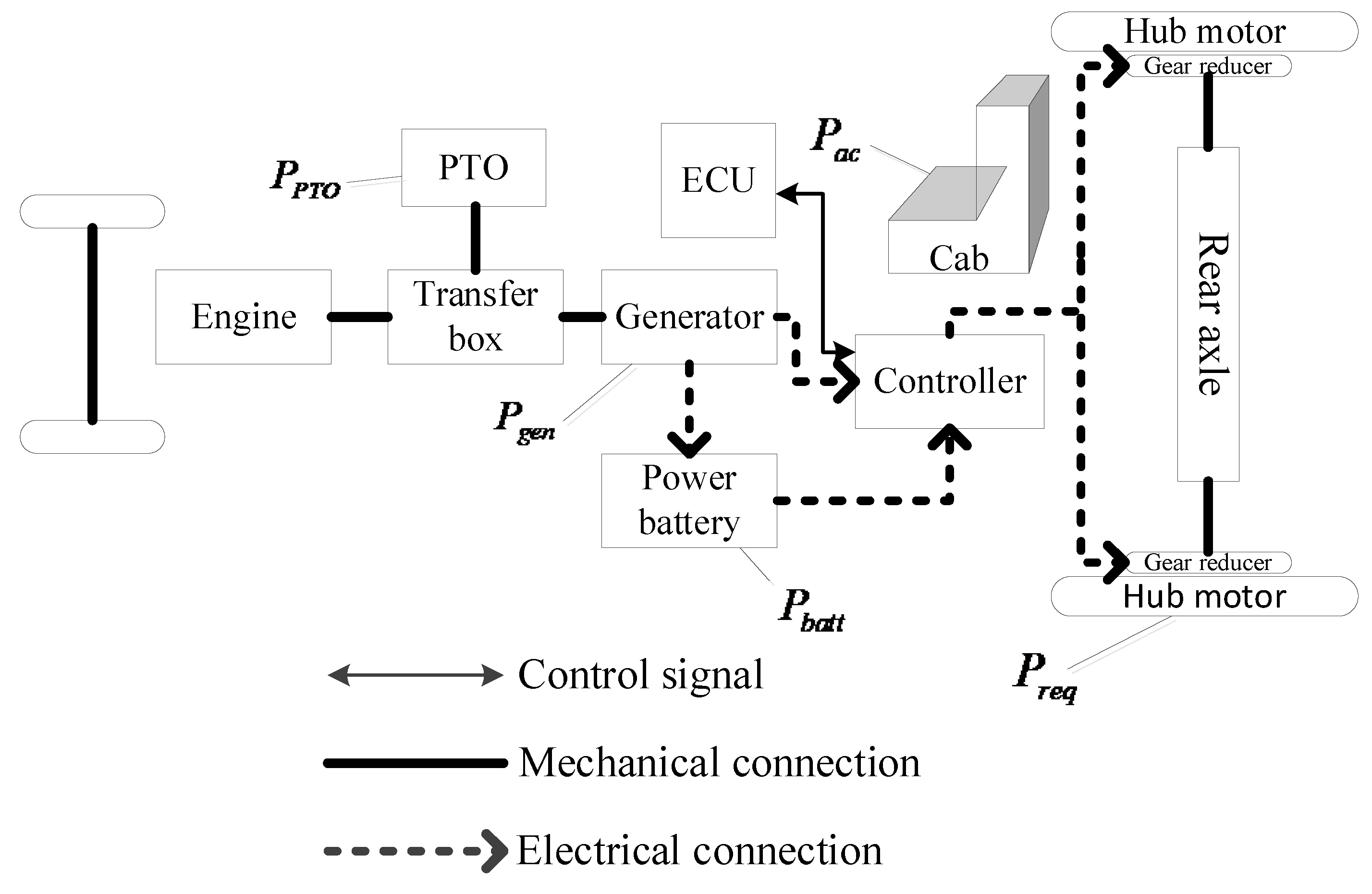
2.1.1. Dynamic Model Design of the Whole Vehicle

As shown in Figure 1, the dynamic model of the tandem hybrid tractor designed in this paper mainly includes the engine/generator set, power battery, PTO (Power Take-Off), tractor accessories, and hub motor models. P g e n is used to represent the output power of the engine/generator set. P b a t t is the output power of the power battery. P P T O is the output power of the transfer box. P a c is the power consumed by the tractor accessories (electronic equipment, etc.). P r e q is the required power of the hub motor. The power of the power battery is positive when discharging and negative when charging.
Therefore, the dynamic mathematical model of the tandem hybrid tractor designed in this paper is as follows:
P g e n + P b a t t P P T O P a c = P r e q
In the formula, the tractor accessories consume little power, and in order to facilitate calculation, Set P a c to 0. The required power of the whole machine can be calculated under certain operating conditions.

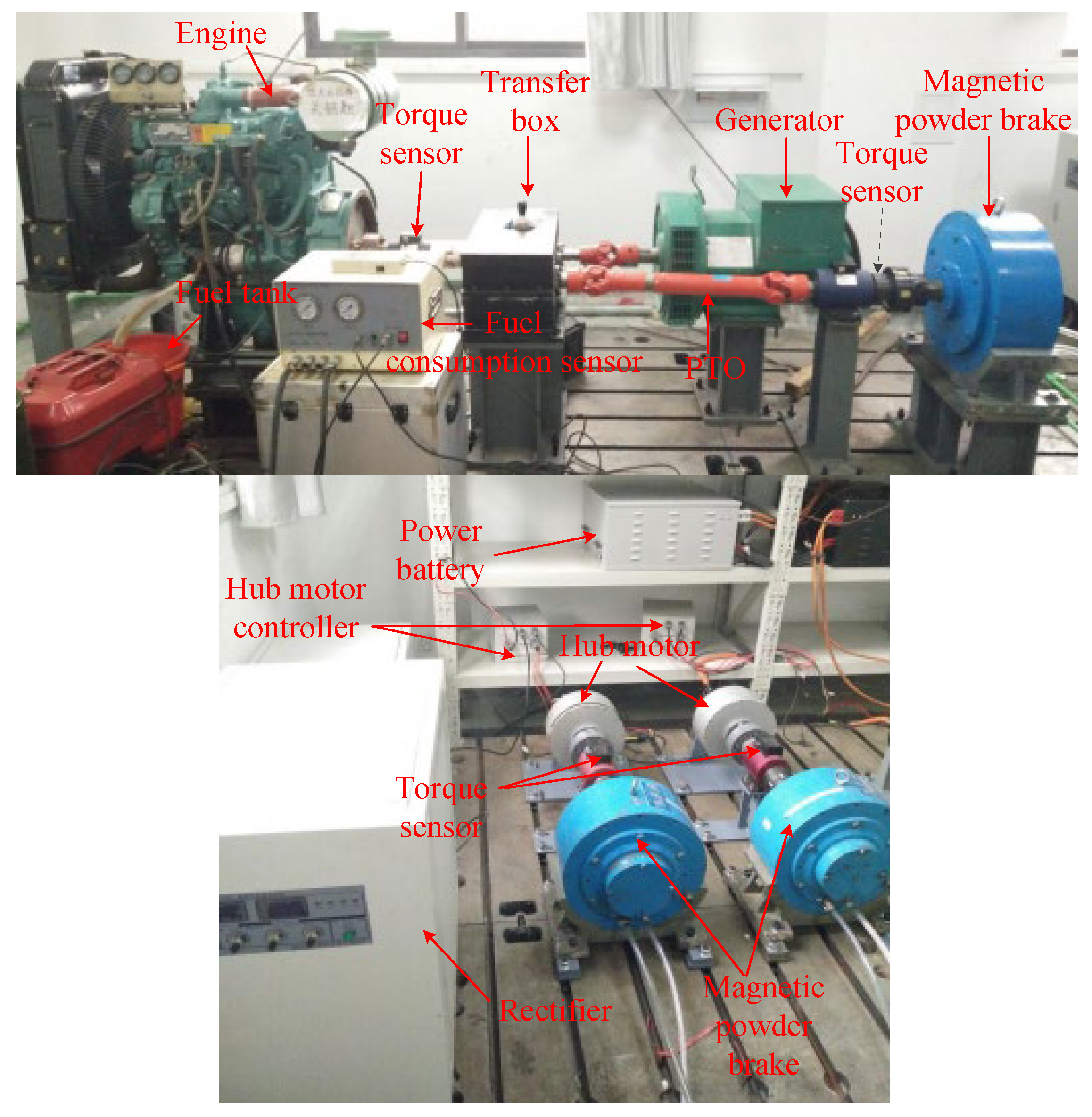
2.1.2. The Construction of the Test Bench

The test bench of the tandem hybrid tractor designed in this paper can be divided into three parts: the drive system, loading, and the sensor acquisition module. As shown in Figure 2, the drive system module mainly includes the engine, transfer box, generator, rectifier, power battery pack, and hub motor. One part of the engine’s power is transferred to the PTO for power output through the transfer box to simulate rotating tillage and other load conditions, and the other part is passed through the generator and rectifier to provide energy for the power battery and hub motor. The loading module mainly has three magnetic powder brakes, which simulate the load encountered by two hub motors in the operation of a hybrid tractor and the load of a PTO in the rotating farming operation. The control of torque is realized by adjusting and controlling the excitation current. The sensor acquisition module has three sets of torque sensors, which are mainly responsible for measuring the speed and torque of the engine, PTO, and hub motor. The fuel consumption sensor is placed between the engine and the fuel tank to measure the fuel consumption of the engine and analyze the economy of hybrid tractor.
(1)
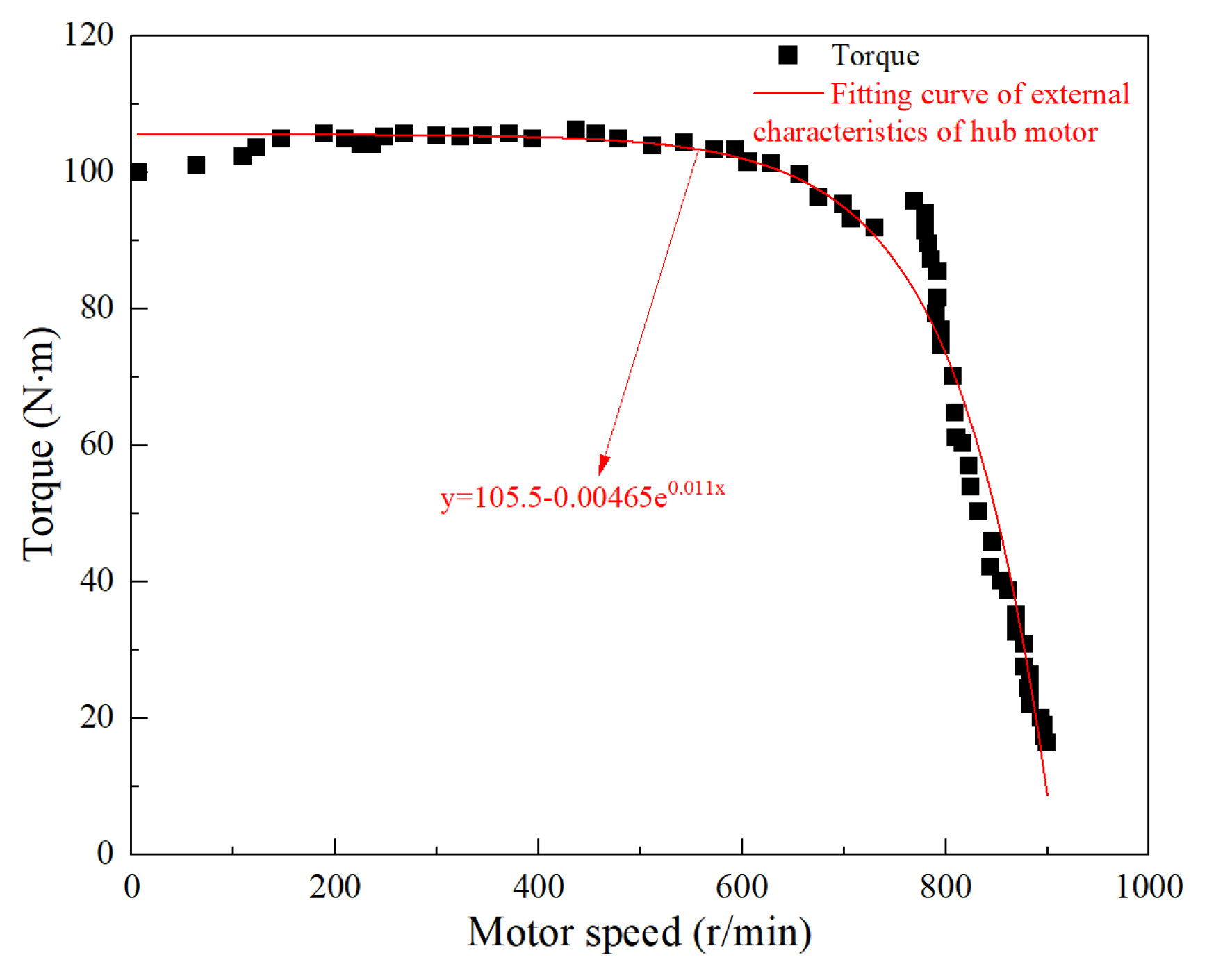
The external characteristic of hub motor
In this paper, by controlling the LabVIEW control program, the excitation current of magnetic powder brake is changed to load the hub motor. The main parameters are shown in Table 1.
The hub motor is gradually accelerated to the highest speed, and then the magnetic powder brake is loaded. In order to measure relatively stable data, the loading voltage each time is 0.1 V and the loading interval is 10–15 s. When the hub motor speed is 0, the loading stopped. The external characteristic of the hub motor is shown in Figure 3.
It can be concluded from Figure 3 that the fitting formula for the external characteristics of the hub motor is as follows:
y = 105.5 0.00465   ×   10 0.011 x
In the formula, x is the speed of the hub motor, and y is the torque. In the test, the maximum speed of the hub motor can reach 900 r/min, and the maximum torque is 106 N·m.
(2)
Optimal working curve of engine/generator set
First of all, the speed of the engine is maintained at the rated speed of 1500 r/min and the generator generates power at a constant frequency. A load is applied to the hub motor through the magnetic powder brake. To change the system’s demand power, that is, to change the output power of the engine. The output torque and speed of the engine are measured by the torque sensor. The fuel consumption of the engine is measured by the fuel consumption instrument. Then, the data points of the minimum fuel consumption per unit time of the engine/generator set under the corresponding output power are obtained. The optimal working curve of the engine/generator set is shown in Figure 4.
When the output power of the engine/generator set is P g e n ( k W ) , the engine fuel consumption per unit time is represented by h ( P g e n ) , whose unit is g/s. The relationship between the output power of the engine and the fuel consumption per unit time is as follows:
h ( P g e n ) = 0.08378 P g e n + 0.1613
In the formula, the output power of the engine/generator set meets 0 P g e n P g e n _ m a x .
(3)
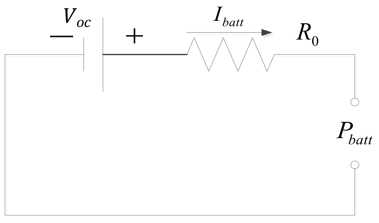
Characteristics of the power battery
The characteristic test of the power battery mainly refers to the charge and discharge characteristic tests. The terminal voltage’s change with the SOC of the power battery is an important basis for studying the energy distribution strategy.
During charging, the power battery terminal voltage corresponding to different SOCs is recorded at an interval of 0.1. When discharging, the discharge current of the power battery is controlled at the rated rate, and the terminal voltage corresponding to different SOCs is recorded at the same interval of 0.1. The charging–discharging characteristic curve of the power battery is shown in Figure 5.
When the SOC range of the power battery is 0.4–0.7, the fluctuation of the terminal voltage is relatively small when charging or discharging, and the working efficiency is relatively high within this working range. Therefore, the operating range of the SOC of the power battery is set to be 0.4–0.7 in the simulation, and the terminal voltage is set to be about 211.5 V. The terminal voltage and internal resistance of the power battery can be regarded as constant values [11,12]. A simplified model of the power battery can be obtained, as shown in Figure 6.
Thus, the mathematical model of the power battery can be obtained as follows:
P b a t t = V o c I b a t t I b a t t 2 R 0
That is, the current in the circuit is as follows:
I b a t t = V o c V o c 2 4 R 0 P b a t t 2 R 0
In the formula, V o c is the terminal voltage, which is the constant 211.5 V. I b a t t is the current, and R 0 is the equivalent internal resistance of the power battery.

2.2. Global Optimization Energy Distribution Strategy Based on PMP

2.2.1. Energy Distribution Model of Tandem Hybrid Tractor

In order to achieve the minimum fuel consumption of the tandem hybrid tractor in the whole operating condition, the optimization objective function of the system is to minimize the fuel consumption of the tractor from the initial time t 0 to the end time t N under cycle conditions. Let the power battery S O C ( t k ) be the state variable and the output power of the power battery P b a t t ( t k ) be the system control variable. Based on the principle of PMP, the following mathematical model of energy distribution can be established:
(1)
Objective function
To achieve the minimum fuel consumption of the tractor under the whole operating condition, the minimum fuel consumption at every moment must be met; that is,
min J = k = 1 N h [ t k , P g e n ( t k ) ]
In the formula, t k is the time, and h [ t k , P g e n ( t k ) ] represents the fuel consumption of the engine/generator set when the output power is P g e n ( t k ) and the engine/generator set is operating along the optimal operating curve. The relationship between them is shown in Formula (3).
(2)
State variable
For a hybrid tractor, during the driving process, the state quantity is the SOC of the power battery. Thus, the change in SOC is the energy consumption of the power battery. It can be expressed by the following formula:
S O C ( t k ) = S O C ( t k 1 ) t k 1 t k V o c I b a t t ( t ) d t
By derivation of the above equation, the state equation of the power battery can be obtained as follows:
S O C ( t k ) = V o c I b a t t ( t k 1 )
In the simulation setting, the final value of SOC of the power battery is equal to the initial value.
S O C ( t N ) = S O C ( t 0 )
During the simulation calculation, the following value is set:
S O C ( t N ) S O C ( t 0 ) = Δ S O C δ
In the formula, δ is a very small positive number.
(3)
Variable constraints
Engine/generator set’s constraint:
P g e n , m i n P g e n P g e n ,   m a x
Power battery’s constraint:
P b a t t , m i n P b a t t ( t k ) P b a t t ,   m a x
In combination with Formula (1), the power battery’s constraint can be obtained:
P r e q t k + P P T O P g e n , m a x P b a t t ( t k ) P r e q t k + P P T O P g e n , m i n
In summary, we can achieve the following:
m a x P b a t t , m i n , ( P r e q t k + P P T O P g e n , m a x ) P b a t t ( t k ) m i n P b a t t , m a x ,   ( P r e q t k + P P T O P g e n ,   m a x )
(4)
Construct the Hamilton function of energy distribution
From the objective function (6) and the state equation of the power battery (8), the Hamilton function of energy distribution is constructed as follows:
H [ ( S O C ( t k ) , P b a t t ( t k ) , λ ( t k ) ] = h [ t k , P g e n ( t k ) ] + λ ( t k ) S O C ( t k )
In the formula, λ ( t k ) is the costate variable. It can be simplified as follows:
H = 0.08378 P g e n + 0.1613 λ ( t k ) V o c V o c V o c 2 4 R 0 P b a t t 2 R o
(5)
Costate equation of Hamilton function
λ ( t k ) = H ( S O C ( t k ) , P b a t t , λ ( t k ) ) S O C
Because the operating range of the SOC of the power battery is set in a fixed range (0.4–0.7), the voltage of the power battery and the internal resistance at this time are approximately constant, so there is λ ( t k ) = 0 , which is as follows:
λ ( 0 ) = λ ( t k ) = c   ( c o n s t a n t   v a l u e )

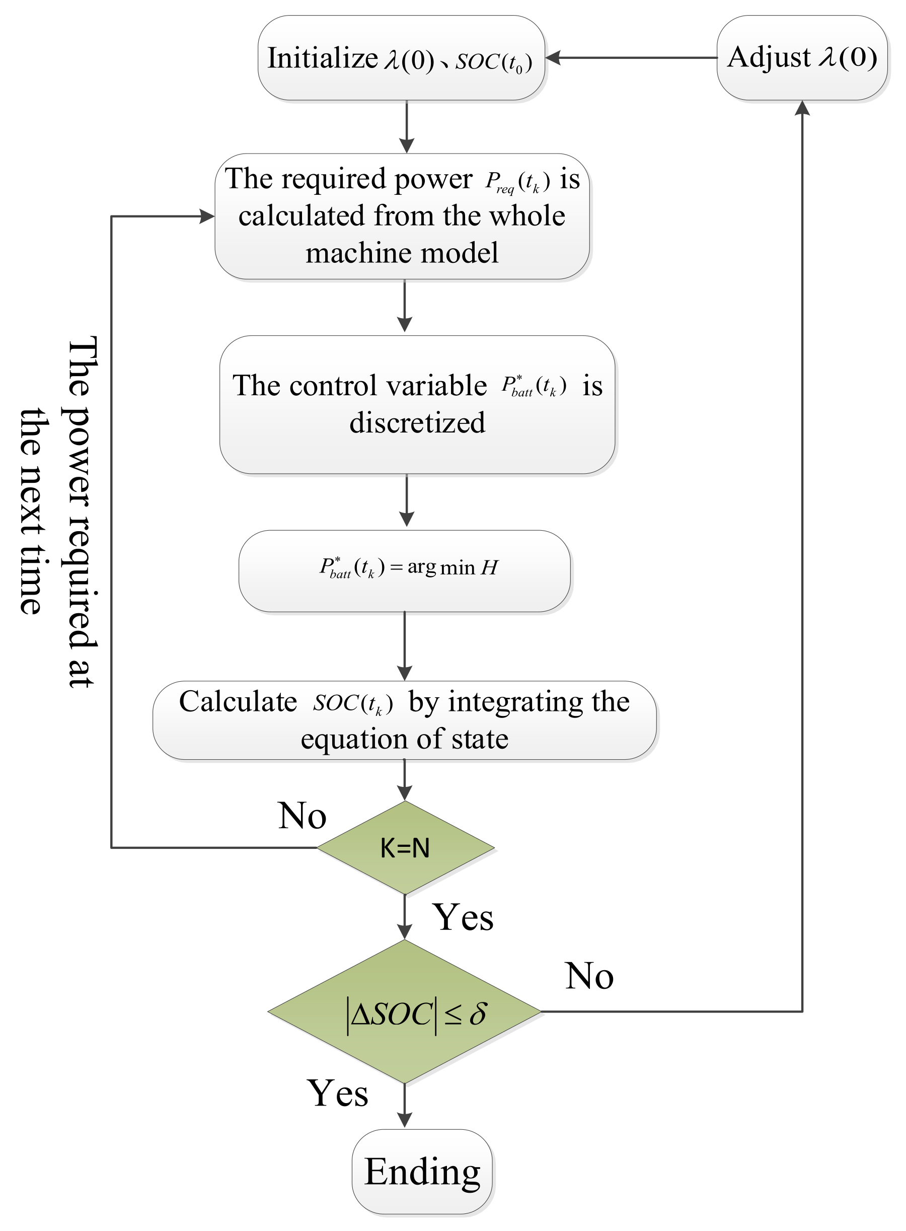
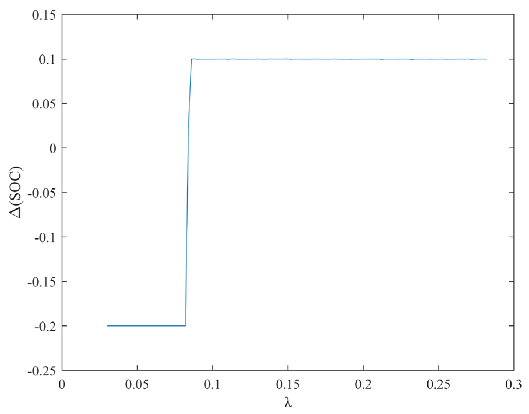
2.2.2. Solving the Optimal Solution of Global Energy Distribution

The necessary condition for minimizing the objective function (6) of the system is to minimize the energy distribution Hamilton function of the system, and the control variable of the system is P b a t t ( t k ) . That is, N optimal control vector sequences P b a t t * ( t k ) can be found at a discrete time t k ,k = 0,1,2,3...N. This meets the following:
P b a t t * t k = a r g m i n P b a t t H ( S O C ( t k ) , P b a t t ( t k ) , λ ( t k ) )
Since the initial value λ ( 0 ) of the costate variable of the whole system is undetermined and affected by S O C ( t k ) , the iterative search method can be used to solve the initial value λ ( 0 ) of the costate variable for a given driving condition. First, the initial value of a costate variable is set in advance, such as between the interval [0,1]. The control variable P b a t t ( t k ) is then discretized between [ P b a t t , m i n ,   P b a t t , m a x ] . The optimal control variable P b a t t * ( t k ) is obtained when the Hamilton function of the whole system is minimized. The value of the final moment S O C ( t N ) is obtained by optimizing the next moment in turn. If the absolute value of the difference between S O C ( t N ) and the initial value S O C ( t 0 ) is less than the set value δ, which is set as 0.001 in this paper, then the costate variable value is the optimal value. Otherwise, the initial value of the costate variable is changed, and the iteration continues until the absolute value of the difference is less than the set value. The specific solving process is shown in Figure 7.

2.3. Analysis of Transport Operation Characteristics of Hybrid Tractors

2.3.1. Transportation Operation Resistance

When the hybrid tractor is in the transport operating condition, it can be regarded as a hybrid power tractor and trailer transport unit. When a tandem hybrid tractor is transported with a trailer on a paved or dirt road, the traction resistance encountered by the tractor is as follows:
F y = ( m s + m n ) g f d cos θ + ( m s + m n ) g sin θ
In the formula, F y is the tractor drag resistance under transportation condition. m s is the structural mass of the tractor. m n is the mass of the trailer. g is the acceleration of gravity, 9.8 N/kg. θ is the slope angle, rad. f d is the rolling resistance coefficient of the road. It is 0.02 for the paved road and 0.04–0.05 for the dirt road. i is the road slope, and the value is shown in Table 2, which is 0.06. The mass of the tractor structure is set to 1600 kg, and trailer is 1000 kg. It can be calculated that when the hybrid tractor is carrying out road transportation with trailer, the traction resistance is 2800 N.

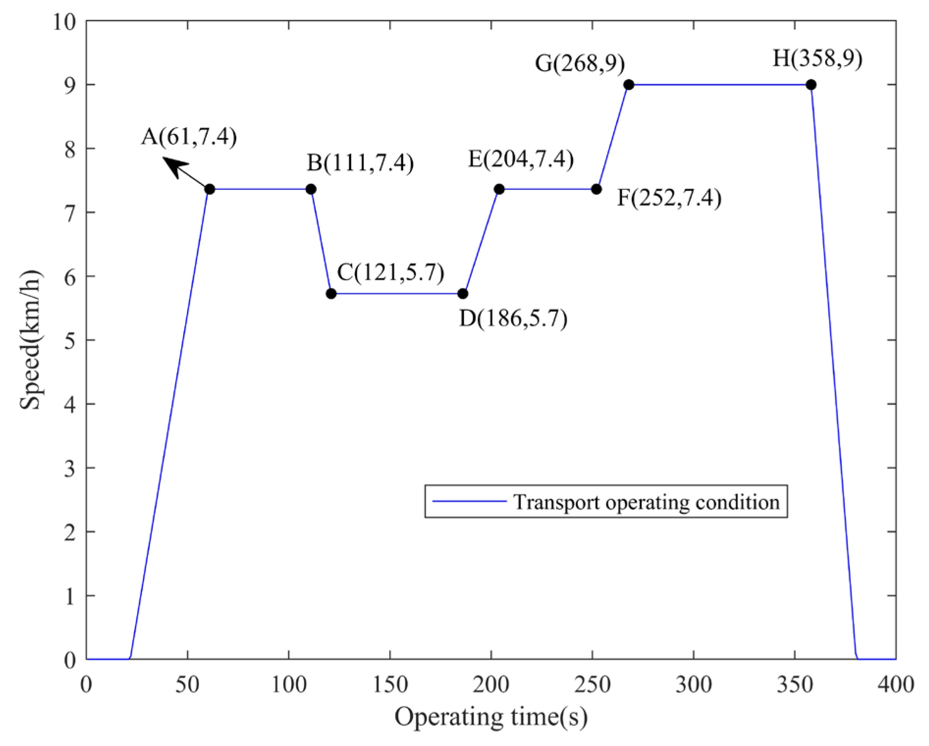
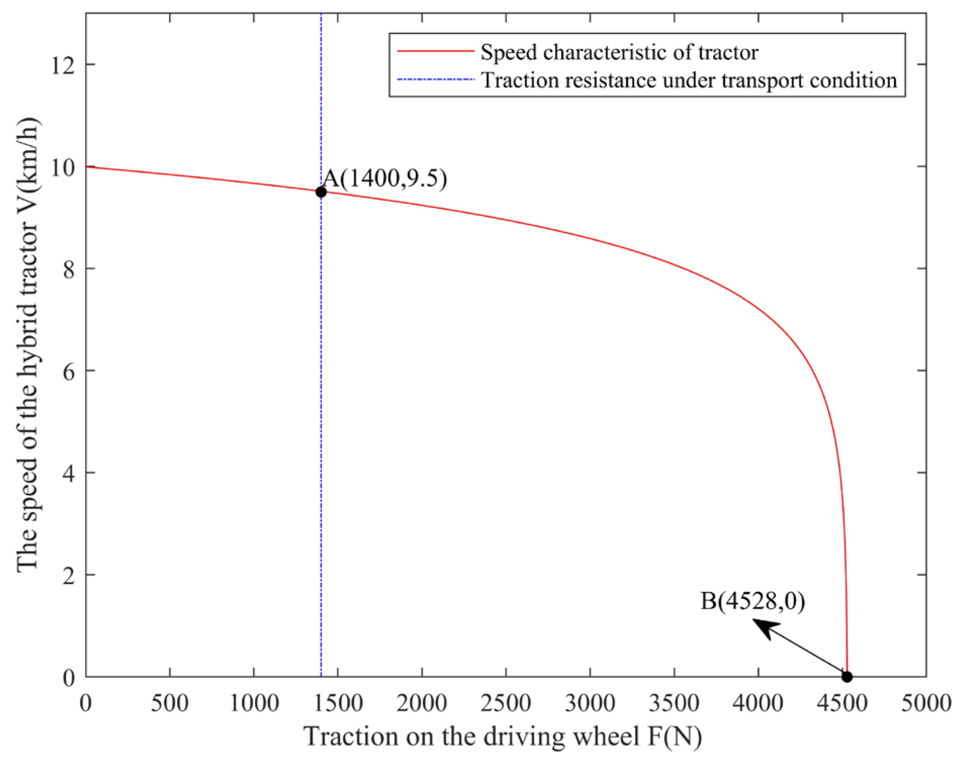
2.3.2. The Speed Characteristics of Transport Operation

In the tandem hybrid tractor designed in this paper, whether the power battery or the engine provides energy, the final form is to drive the hub motor in the form of electric energy to carry out different operations. The mechanical energy of the hub motor drives the rear wheel of the tractor to rotate after being decelerated by the reducer. Therefore, the driving force acting on the rear wheel is as follows:
F 1 = M 1 r = M m η m i r
In the formula, F 1 is the driving force. M 1 is the torque received by the driving wheel. r is the radius of the driving wheel, which is 0.64 m. M m is the output torque of the hub motor. η m is the transmission efficiency of the hub motor, which is 0.98. i is the deceleration ratio, which is 21.
According to Section 2.3.1, the traction resistance overcome by each driving wheel is 1400 N. The external characteristic curve of the hub motor can be obtained from Equation (2), and the theoretical traveling speed characteristics of the tandem hybrid tractor under transportation operation can be known, as shown in Figure 8.
Therefore, when the hybrid tractor is under the transport condition, the traction resistance to overcome is 1400 N. At this time, the corresponding tractor operating speed range is 0–9.5 km/h.

3. Results and Discussion

3.1. Simulation Model

ADVISOR simulation software combines backward simulation and forward simulation. Backward simulation is the main and the forward is the auxiliary one [21,22,23]. For the tandem hybrid tractor designed in this paper, the simulation process is shown in Figure 9.
Based on the analysis of the simulation process of serial hybrid tractor, the whole simulation model is established. As shown in Figure 10, among them, there are the simulation parameter module of the whole vehicle (vehicle), wheel/axle (wheel/axle), wheel edge reducer (fd), transmission (transmission), motor (motor), engine/generator set (fc/gc), power battery (energy storage), and other components. The parameters related to the tandem hybrid tractor in the M file of ADVISOR are shown in Table 3.

3.2. Setting of Transport Operating Condition

In the process of transport operation, according to the theoretical travel speed configuration of agricultural tractors, the maximum transport speed of tractors is 16–30 (40) km/h [24]. According to different laws and regulations of various countries, the transport speed of wheeled tractors is generally not more than 25 or 30 km/h, and 40 km/h is also allowed. As shown in Figure 11, the low-speed of Extra Urban Driving Cycle (EUDC) is taken as the test working condition under the transport operating condition of the tandem hybrid tractor designed in this paper [25,26]. According to the analysis in Section 2.3.2, the running time of a single working condition is set at 400 s. The idle time is 40 s, and the maximum speed is 9 km/h. The running mileage is 0.68 km, and the average speed is 6.74 km/h. Five working cycles are set in the simulation.

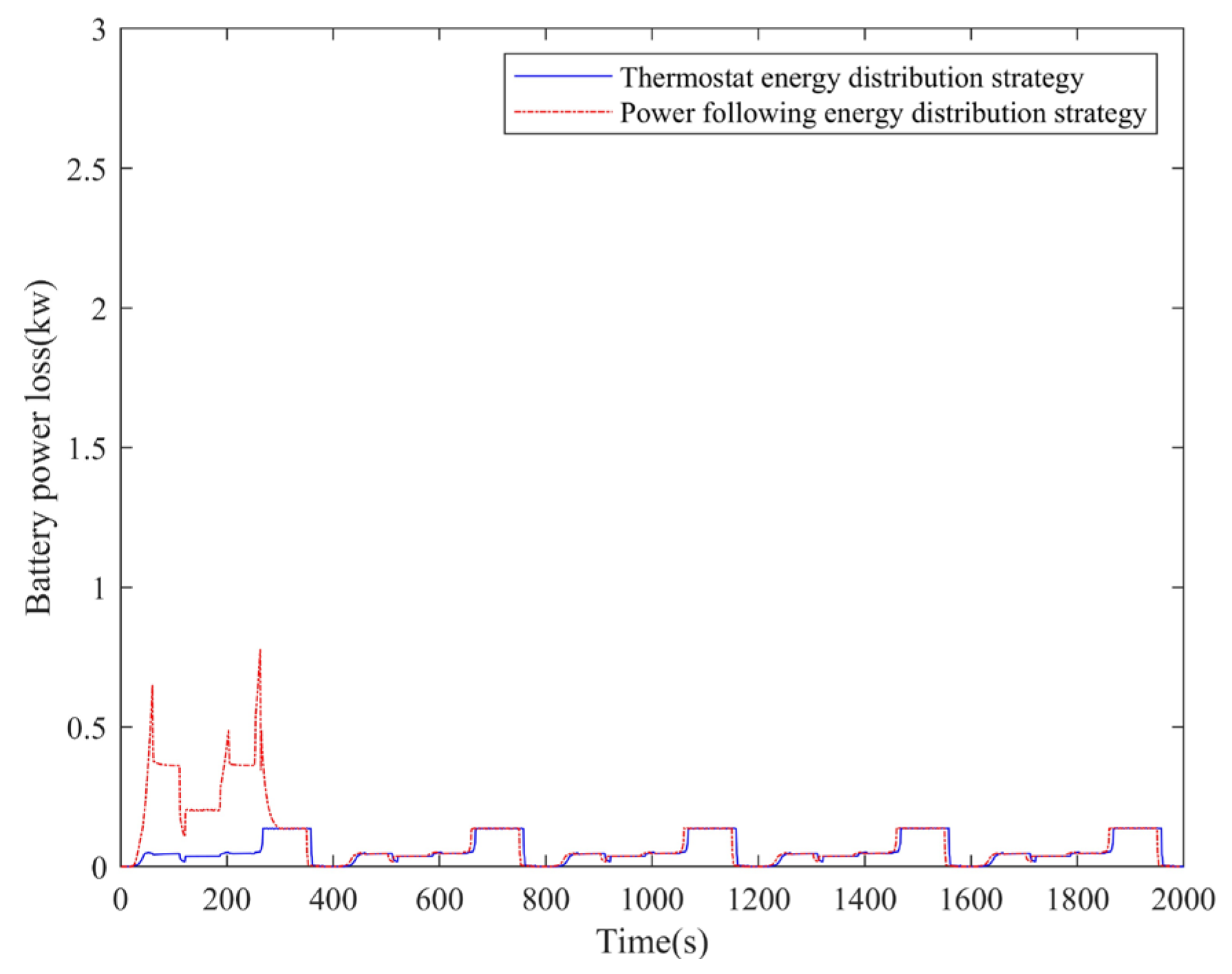
3.3. Results Based on Thermostat and Power-Following Energy Distribution Strategy

As shown in Figure 12, the output power curve of the engine/generator set and the power battery alternate under the thermostat distribution strategy. At the end of the simulation, the total fuel consumption is 500.23 g and the diesel fuel density is 0.86 g/mL, so the fuel economy of the final simulation result is 17.26 L/100 km. Under the power-following distribution strategy, in the initial stage of the first operating condition of the simulation, the engine/generator set basically does not work, and the required power is provided by the power battery. In subsequent conditions, the engine/generator set works together with the power battery. As shown in Figure 13, the SOC value of the power battery decreases continuously under the thermostat-type distribution strategy. Eventually, it drops to around 0.56. Under the power-following distribution strategy, the SOC value of the power battery finally reduces to about 0.55. At the end of the simulation, the total fuel consumption was 454.15 g, so the fuel economy of the final simulation result is 15.67 L/100 km.
As shown in Figure 14 and Figure 15, under all cycle conditions, the maximum power loss of the power battery under the thermostat energy distribution strategy is close to 0.14 kW, while that under the power-following distribution strategy is close to 0.8 kW.

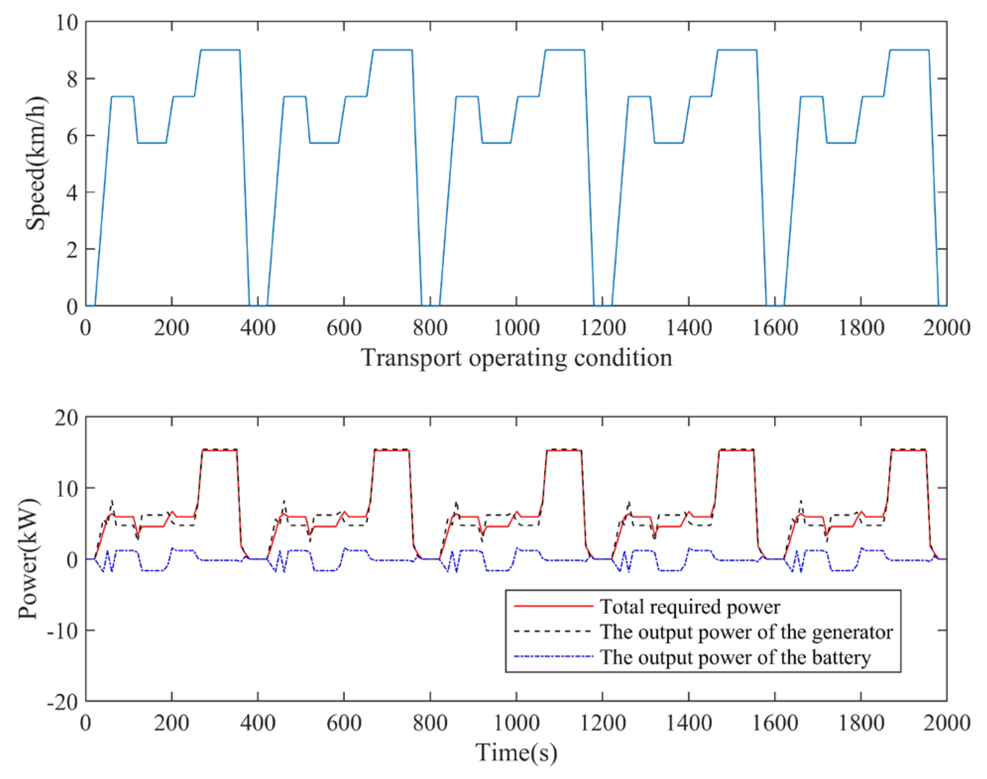
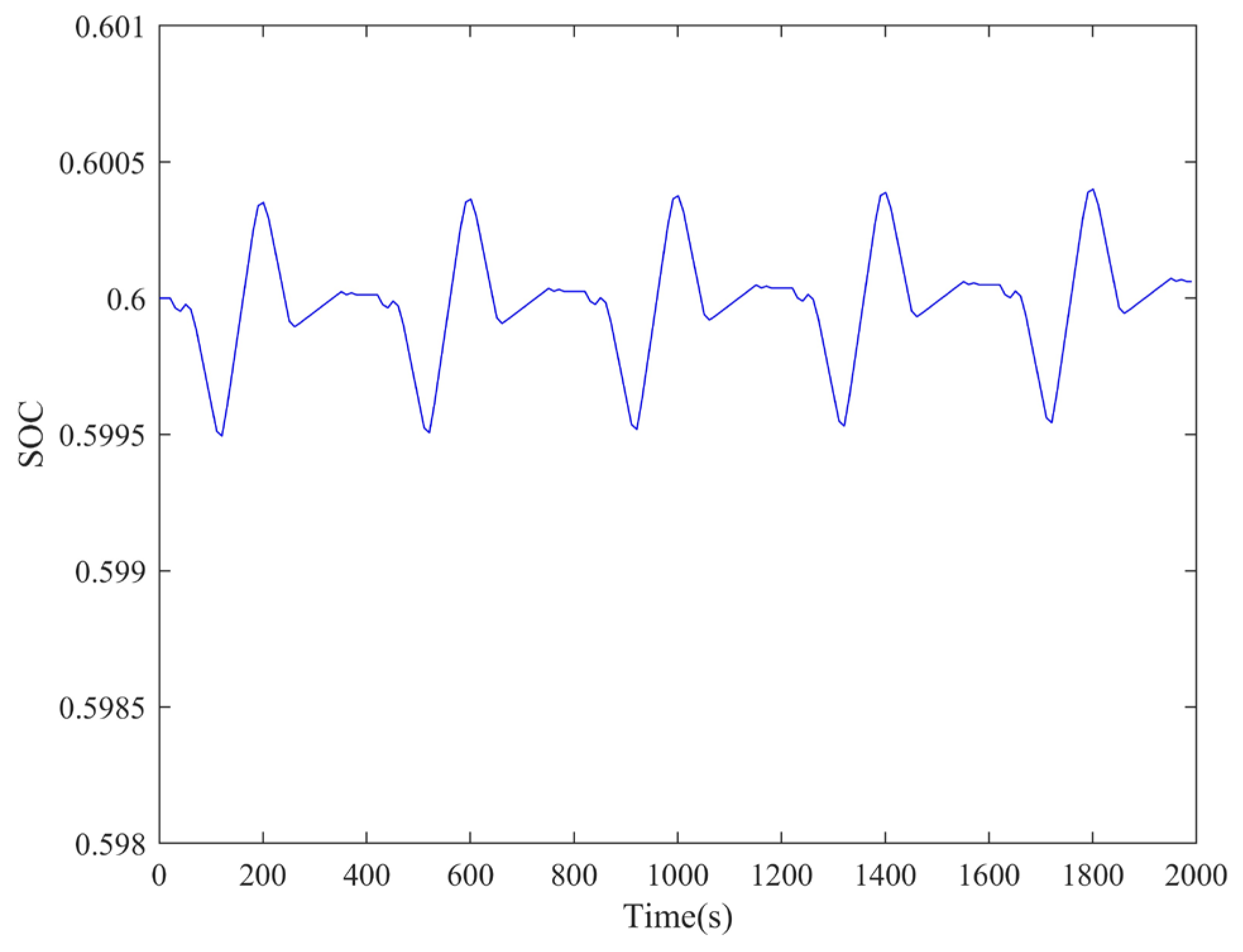
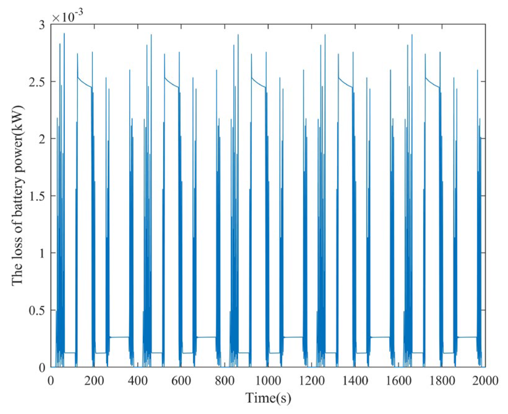
3.4. Results of Global Optimization Energy Distribution Based on PMP

As shown in Figure 15, the output power curve of the engine/generator set and the power battery under the PMP distribution strategy changes alternately. As shown in Figure 16, the final SOC value of the power battery at the end of the simulation is maintained at about 0.6, which is equal to the initial value of the simulation. At the end of the simulation, the total fuel consumption was 335.61 g, and the fuel economy of the final simulation result was 11.58 L/100 km. Meanwhile, the influence of the initial costate value λ ( 0 ) on Δ ( S O C ) is shown in Figure 17. λ ( 0 ) varies from 0.026 to 0.283, corresponding Δ ( S O C ) varies from −0.2 to 0.1. Δ ( S O C ) remains at −0.2 when λ ( 0 ) is less than 0.076, and at 0.1 when λ ( 0 ) is greater than 0.1. For Δ ( S O C ) to be as close to 0 as possible, the costate parameter λ ( 0 ) = 0 .0838.
As shown in Figure 18, the peak power loss of the power battery is close to 3 × 10 3 kW under the whole operating condition. With the simulation, it can be seen that the power loss of the power battery changes little with the load.

3.5. Comparative Analysis

The charge and discharge of power batteries based on thermostat distribution strategies are frequent. The overall system power loss is large, and the energy conversion rate is low. In the power-following energy distribution strategy, for the engine, the working area of the engine becomes larger and changes rapidly, which will cause damage to the efficiency and emission performance of the engine, thereby reducing its overall efficiency. The global optimal energy distribution strategy based on PMP not only considers the charge and discharge of the power battery but also keeps the engine working in the best area. Based on the analysis of the results of thermostat, power-following, and PMP-based energy distribution strategies, it can be concluded that under transport conditions, the comprehensive fuel consumption of the tandem hybrid tractor and the power loss of the power battery are shown in Table 4. It can be seen that the power loss of the power battery is significantly reduced compared with the first two under the transportation condition with the PMP strategy. At the same time, the fuel economy is significantly improved compared with the thermostat type and power-following type. The combined fuel consumption decreases by 32.91% and 26.10%, respectively.

4. Conclusions

In this paper, the research object concerns a tandem hybrid tractor that adopts a novel hybrid structure driven by a hub motor. The test bench is designed and built to study the main power components. The performance parameters of the engine/generator set, power battery, and hub motor are obtained. The mathematical model of the whole vehicle, engine/generator set, and power battery are established.
An energy distribution strategy based on PMP is proposed for a tandem hybrid tractor, which is analyzed from the aspects of energy distribution objective function, state variable, and variable constraint. Compared with the traditional thermostat distribution strategy and power-following energy distribution strategy, it can effectively reduce the loss of the power battery, and the fuel economy of a tandem hybrid tractor is significantly improved.
The co-simulation based on Matlab/Simulink and ADVISOR is complete. The simulation process is analyzed to establish the ADVISOR simulation model of the tandem hybrid tractor. Based on the analysis of the transportation characteristics of the hybrid tractor, the transport condition of the tractor is set. The results show that, compared with the thermostat and power-following energy distribution strategy, the PMP-based energy distribution strategy can reduce the combined fuel consumption of tandem hybrid tractor by 32.91% and 26.10%, respectively. The feasibility of this strategy has been verified. It is of great significance to improve the efficiency of agricultural machinery and reduce the fuel consumption of agricultural machinery.

Author Contributions

Methodology, R.Z.; software, R.Z. and C.S.; validation, R.Z.; investigation, R.Z. and S.F.; resources, Z.L. and X.D.; writing—original draft preparation, Z.L.; writing—review and editing, L.W., R.Z. and Z.L.; supervision, Z.L.; project administration, L.W., Z.L. and X.D. All authors have read and agreed to the published version of the manuscript.

Funding

This study was funded by the Open Project of the State Key Laboratory of Intelligent Agricultural Power Equipment (SKLIAPE2023019), the Research Project of Nanjing Institute of Railway Technology (Yz230001), the Jiangsu Qinglan Project, and the National Key Research and Development Plan (2022YFD2001202).

Institutional Review Board Statement

Not applicable.

Data Availability Statement

The data presented in this study are available on demand from the corresponding author or first author at [email protected] or [email protected].

Acknowledgments

The authors thank the National Key Research and Development Plan (2022YFD2001202), the Research Project of Nanjing Institute of Railway Technology (Yz230001), the Project supported by Jiangsu Qinglan Project, and the Open Project of the State Key Laboratory of Intelligent Agricultural Power Equipment (SKLIAPE2023019) for funding. The authors also thank the anonymous reviewers for providing critical comments and suggestions that improved the manuscript.

Conflicts of Interest

The authors declare no conflicts of interest.

References

  1. Liu, M.; Lei, S.; Zhao, J.; Meng, Z.; Zhao, C.; Xu, L. Review on development and Research Status of Electric Tractor. Trans. Chin. Soc. Agric. Mach. 2022, 53, 348–364. [Google Scholar]
  2. Savickas, D.; Steponavičius, D.; Kemzūraitė, A. A novel approach for analysing environmental sustainability aspects of combine harvester through telematics data. Part I: Evaluation and analysis of field tests. Precis. Agric. 2024, 25, 100–118. [Google Scholar] [CrossRef]
  3. Li, Y.; Liu, M.; Wang, Y.; Xu, L.; Lei, S. Energy Management Optimization and Validation of a Hydrogen Fuel Cell-Powered Agricultural Tractor Based on Hierarchical Dynamic Programming. IEEE Access 2024, 12, 21382–21401. [Google Scholar] [CrossRef]
  4. Chen, Z.; Zhou, N. Energy Management Strategy and Swarm Intelligence Optimization for Hybrid Electric Vehicles; Tsinghua University Press: Beijing, China, 2023; pp. 39–40. [Google Scholar]
  5. Hu, X.; Tang, X.; Liu, T. Hybrid Electric Vehicles Energy Management Strategies; China Machine Press: Beijing, China, 2020; pp. 33–34. [Google Scholar]
  6. Sorrentino, M.; Rizzo, G.; Arsie, I. Analysis of a rule-based control strategy for on-board energy management of series hybrid vehicles. Control Eng. Pract. 2011, 19, 1433–1441. [Google Scholar] [CrossRef]
  7. Zhang, E. Research on Energy Distribution Control Strategy of Parallel Hybrid Vehicle. Master’s Thesis, Shenyang University of Technology, Shenyang, China, 2019. [Google Scholar]
  8. Gan, W. Energy Management Strategy and Transmission Parameter Optimization of Parallel Hybrid Electric Vehicle Based on Dynamic Programming. Master’s Thesis, Wuhan University of Technology, Wuhan, China, 2017. [Google Scholar]
  9. Hu, X. Research on PHEV Energy Management Strategy Based on PSO and Neural Network. Master’s Thesis, Wuhan University of Technology, Wuhan, China, 2011. [Google Scholar]
  10. Wu, Z. Research on Energy Management Strategy of Hybrid Electric Vehicle Based on Neural Network and PMP. Master’s Thesis, Southeast University, Nanjing, China, 2018. [Google Scholar]
  11. Lijun, Q.; Lihong, Q.; Fulong, X.; Peng, C.; Jinbo, W. Energy management control strategy and optimization of plug-in four-wheel drive hybrid electric vehicle. J. Agric. Eng. 2015, 31, 68–76. [Google Scholar]
  12. Zhang, Y.; Liu, H.P.; Guo, Q. Varying-Domain Optimal Management Strategy for Parallel Hybrid Electric Vehicles. IEEE Trans. Veh. Technol. 2014, 63, 603–616. [Google Scholar] [CrossRef]
  13. Zhou, Y. Research on Optimal Control Method of Hybrid Electric Vehicle. Master’s Thesis, Hunan University: Changsha, China, 2018. [Google Scholar]
  14. Xu, W.; Xu, L.; Liu, M.; Zhang, Y.; Song, L. Research on energy management strategy of hybrid tractor based on layered decoupling. J. Phys. Conf. Ser. 2022, 2343, 012018. [Google Scholar] [CrossRef]
  15. Zhu, Z.; Zeng, L.; Chen, L.; Zou, R.; Cai, Y. Fuzzy Adaptive Energy Management Strategy for a Hybrid Agricultural Tractor Equipped with HMCVT. Agriculture 2022, 12, 1986. [Google Scholar] [CrossRef]
  16. Zhang, J.; Feng, G.; Liu, M.; Yan, X.; Xu, L.; Shang, C. Research on Global Optimal Energy Management Strategy of Agricultural Hybrid Tractor Equipped with CVT. World Electr. Veh. J. 2023, 14, 127. [Google Scholar] [CrossRef]
  17. Marzougui, H.; Kadri, A.; Martin, J.P.; Amari, M.; Pierfederici, S.; Bacha, F. Implementation of energy management strategy of hybrid power source for electrical vehicle. Energy Convers. Manag. 2019, 195, 830–843. [Google Scholar] [CrossRef]
  18. Francesco, M. A Model-Based Design Approach for a Parallel Hybrid Electric Tractor Energy Management Strategy Using Hardware in the Loop Technique. Vehicles 2020, 3, 1–19. [Google Scholar]
  19. Ghobadpour, A.; Mousazadeh, H.; Kelouwani, S.; Zioui, N.; Kandidayeni, M.; Boulon, L. An intelligent energy management strategy for an off-road plug-in hybrid electric tractor based on farm operation recognition. IET Electr. Syst. Transp. 2021, 11, 333–347. [Google Scholar] [CrossRef]
  20. Lombardi, S.; Di Ilio, G.; Tribioli, L.; Jannelli, E. Optimal design of an adaptive energy management strategy for a fuel cell tractor operating in ports. Appl. Energy 2023, 352, 121917. [Google Scholar] [CrossRef]
  21. Zeng, X.; Gong, W. ADVISOR2002 Electric Vehicle Simulation and Redevelopment Application; Machinery Industry Press: Beijing, China, 2017; pp. 1–5. [Google Scholar]
  22. Tong, G.; Guan, J. Parameter design of FSEC racing car power system based on ADVISOR. J. Shenyang Univ. Aeronaut. Astronaut. 2017, 34, 38–43. [Google Scholar]
  23. Xu, S.; Yan, Y. Research and simulation of energy control strategy for pure electric vehicle based on advisor. In IOP Conference Series: Earth and Environmental Science; IOP Publishing: Bristol, UK, 2019; Volume 252, p. 032034. [Google Scholar]
  24. Luoyang Tractor Research Institute, Ministry of Mechanical and Electronic Industry. Tractor Design Manual; Machinery Industry Press: Beijing, China, 1994; p. 69. [Google Scholar]
  25. Gao, H. Research on Electric Tractor Drive System. Ph.D. Thesis, Nanjing Agricultural University, Nanjing, China, 2008. [Google Scholar]
  26. Sun, Y. Research on Energy Management of Pure Electric Tractor Based on Super Capacitor Auxiliary Energy. Master’s Thesis, Jiangsu University, Zhenjiang, China, 2018. [Google Scholar]
Figure 1. Dynamic model of tandem hybrid tractor.
Agriculture 14 00440 g001
Figure 2. Tandem hybrid tractor test bench.
Agriculture 14 00440 g002
Figure 3. The curve of the external characteristic of the hub motor.
Agriculture 14 00440 g003
Figure 4. Optimal working curve of engine/generator set.
Agriculture 14 00440 g004
Figure 5. Relationship between terminal voltage and SOC in charging and discharging of power battery.
Agriculture 14 00440 g005
Figure 6. The simplified model of power battery.
Agriculture 14 00440 g006
Figure 7. Calculation flow of PMP global optimal control.
Agriculture 14 00440 g007
Figure 8. Theoretical travel speed characteristics under transport condition.
Agriculture 14 00440 g008
Figure 9. Simulation process of ADVISOR for tandem hybrid tractor.
Agriculture 14 00440 g009
Figure 10. ADVISOR simulation model of tandem hybrid tractor.
Agriculture 14 00440 g010
Figure 11. Tractor transport operating condition.
Agriculture 14 00440 g011
Figure 12. Output power curve of engine/generator set.
Agriculture 14 00440 g012
Figure 13. SOC curve of power battery.
Agriculture 14 00440 g013
Figure 14. Loss of battery power.
Agriculture 14 00440 g014
Figure 15. Output power curve of engine/generator set under PMP strategy.
Agriculture 14 00440 g015
Figure 16. SOC curve of power battery under the PMP strategy.
Agriculture 14 00440 g016
Figure 17. Influence of λ ( 0 ) on Δ ( S O C ) under transportation condition.
Agriculture 14 00440 g017
Figure 18. Loss of battery power.
Agriculture 14 00440 g018
Table 1. Parameters of the magnetic powder brake.
ModelQuantityRated Torque (N·m)Field Current (A)Allowable Slip Power (kW)Cooling Mode
CZ-5025002.514Water-cooling
Table 2. Maximum slopes of various roads (%).
RegionPaved RoadSmooth RoadUnpaved RoadField Road
Plain45~678
Hill56~7810
Mountainous region77~88~1012
Table 3. Parameters of the whole tractor simulation.
Parameter NameParameterValueUnit
Drag coefficientveh_CD0-
Windward areaveh_FA0m2
Percentage of front axle load to total machine massveh_front_wt_frac0.4-
Height of center of massveh_cg_height0.85m
wheelbaseveh_wheelbase2m
Overall qualityVeh_mass1600kg
Maximum loading massveh_cargo_mass300kg
Table 4. Fuel consumption and consumption of tandem hybrid tractor under transport condition.
Energy Distribution StrategyFuel Consumption (L/100 km)Power Battery Pack Loss (kW)Fuel Consumption Reduction (%)
Thermostat17.260.1432.91
Power-following15.670.826.10
PMP11.58 3 × 10 3 -
Disclaimer/Publisher’s Note: The statements, opinions and data contained in all publications are solely those of the individual author(s) and contributor(s) and not of MDPI and/or the editor(s). MDPI and/or the editor(s) disclaim responsibility for any injury to people or property resulting from any ideas, methods, instructions or products referred to in the content.

