
Design of and Experiments with an Automatic Cuttage Device for an Arch Shed Pillar with Force Feedback

 and
and
Abstract
:1. Introduction
- (1)
- The cuttage span of the arch shed pillar should be 60 cm with less than 1 cm of error;
- (2)
- The height of the arch shed pillar after cuttage should be 40 cm with less than 1 cm of error;
- (3)
- The diameter of the arch shed pillar that can be cut should be 1 cm;
- (4)
- The cuttage depth should be equal at the ends of the arch shed pillar;
- (5)
- The damage rate of the arch shed pillar should remain below 5%;
- (6)
- The cuttage device should operate smoothly, have optimal stability, and have a long service life.
- (1)
- Suitable pillar cuttage depth;
- (2)
- A quick and convenient method for determining the ideal cuttage depth at both ends of the pillar;
- (3)
- Ensuring that the damage rate of the pillar is controlled below 5%;
- (4)
- Ensuring the optimal operation and stability of the device.
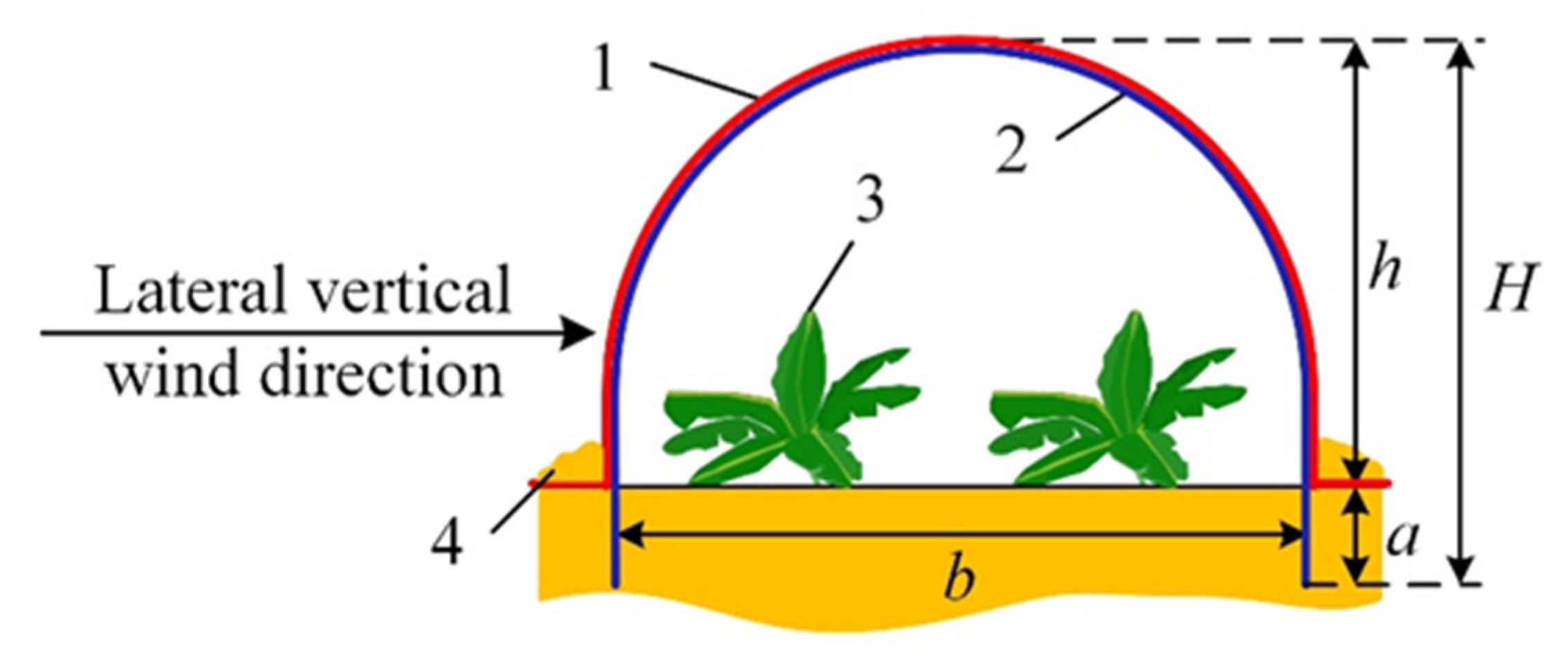
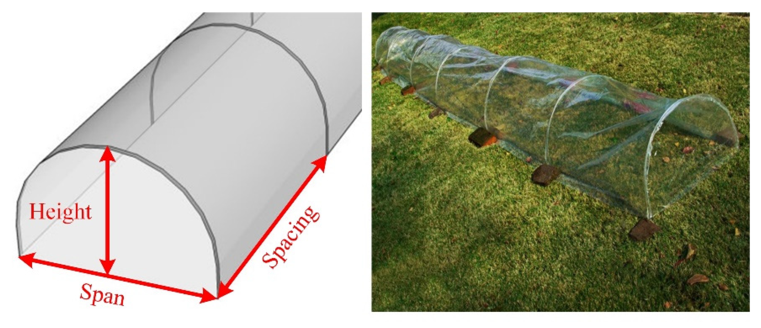
2. Pillar Cuttage Depth and Wind Resistance Analysis of the Arch Shed
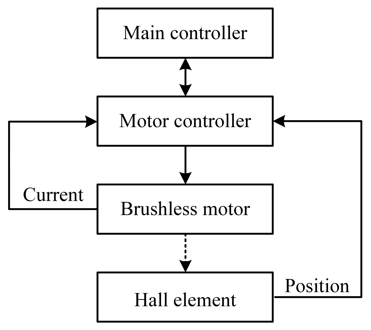
3. Real-Time Detection Principle of Cuttage Depth Based on “Current–Force–Depth”
4. Simulation Analysis of Cuttage Device
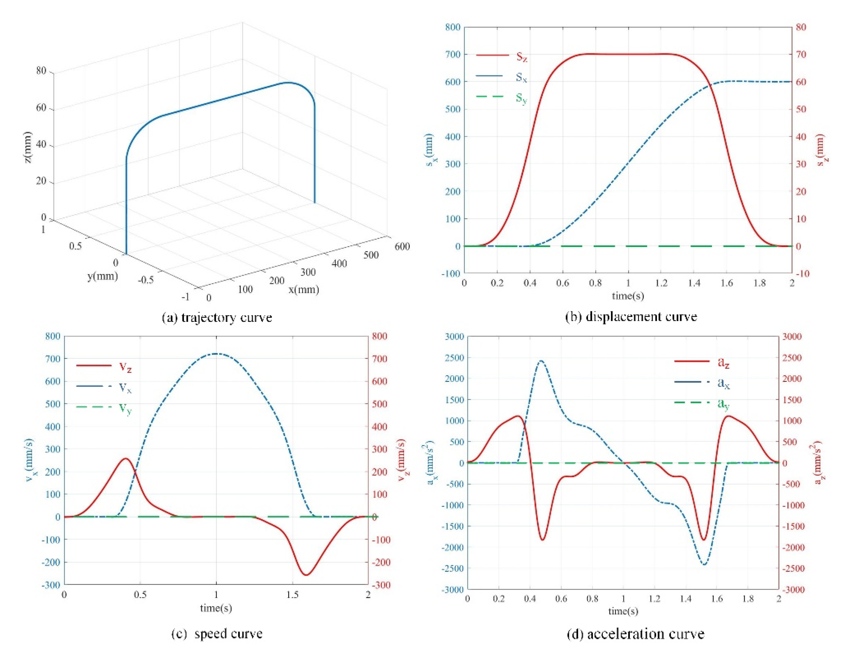
4.1. Simulation Analysis of the Motion Trajectory of the Execution End
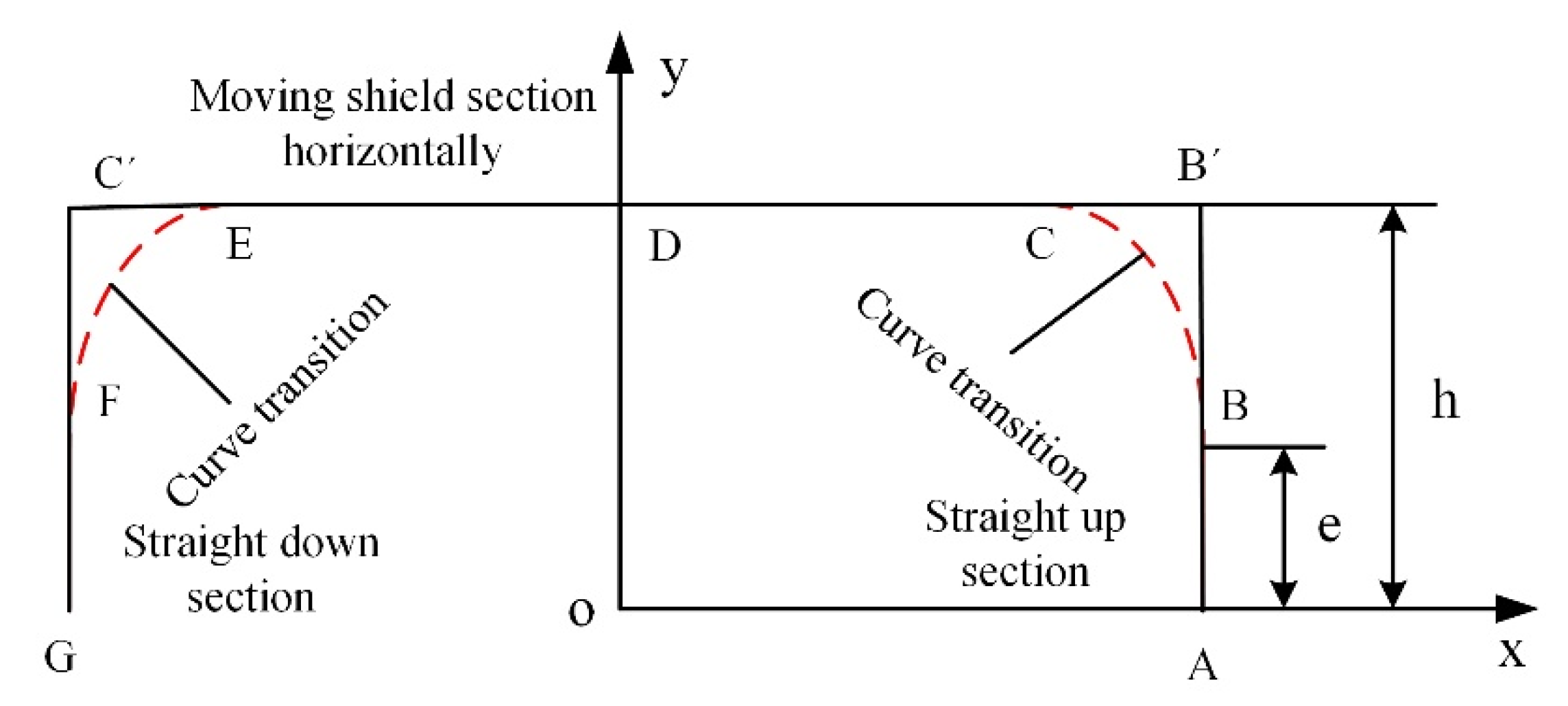
- (1)
- When , the execution end moves along the AB segment, and the kinematic parameters of the execution end are:
- (2)
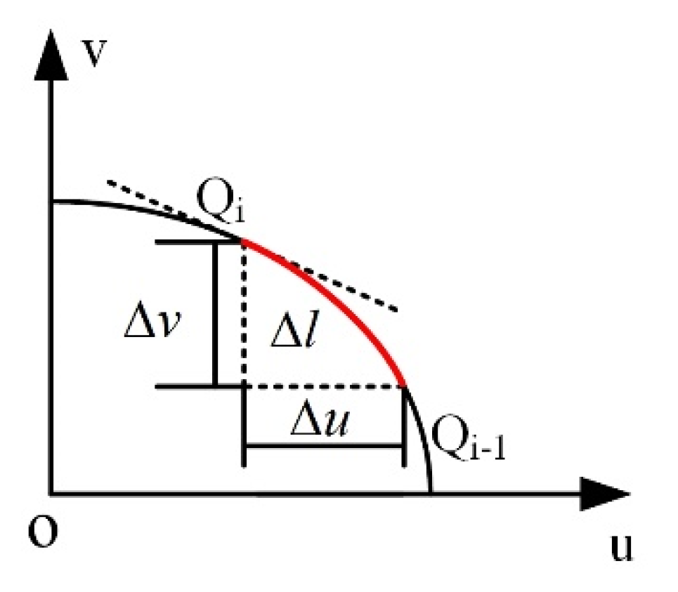
- When the execution end moves within the segment along the Láme curve, the kinematic parameters of the execution end are solved according to the arc differentiation method, as shown in Figure 8:
- (3)
- When the execution end moves within the CD segment, the motion parameters of the execution end at time are:
- (4)
- The left and right sides of the motion trajectory of the execution end are symmetrical and the physical parameters of the second half of the motion are determined as described above.
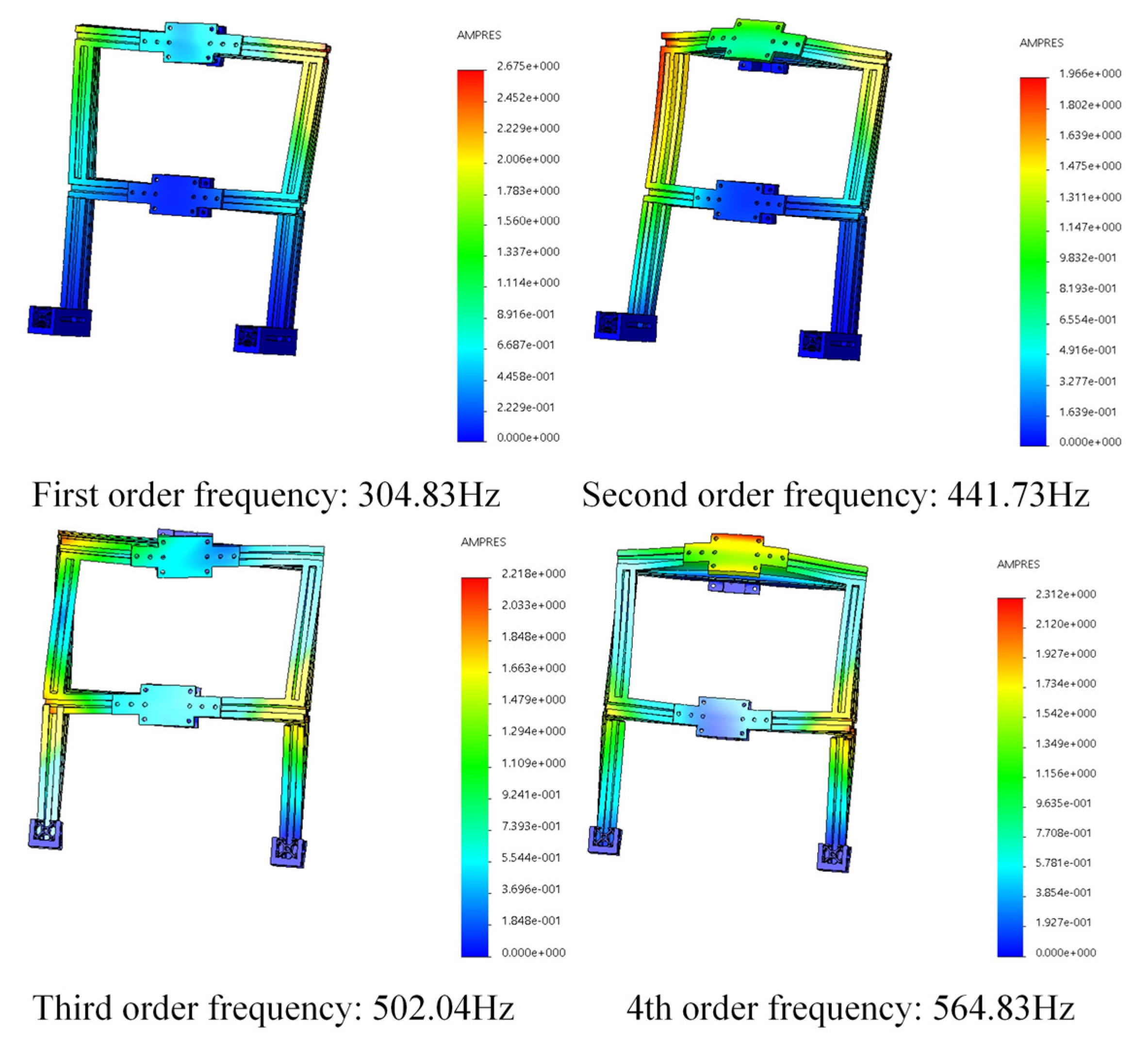
4.2. Modal Analysis of the Installation Frame
5. Experimental Results and Analysis
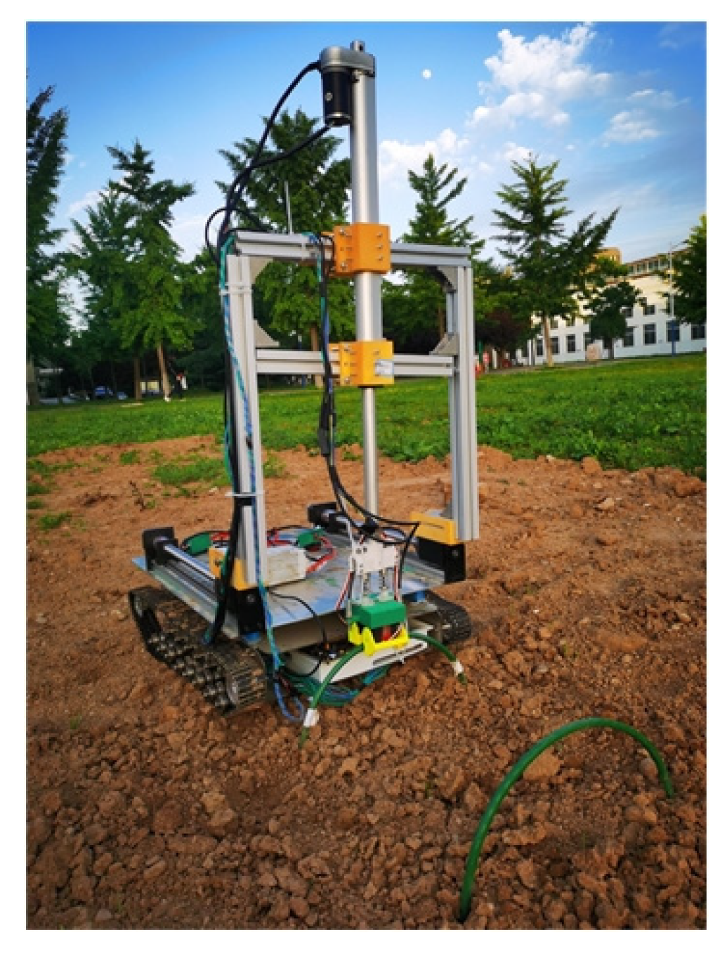
5.1. Construction of Entity System
5.2. Verification Experiment of the Cuttage Depth
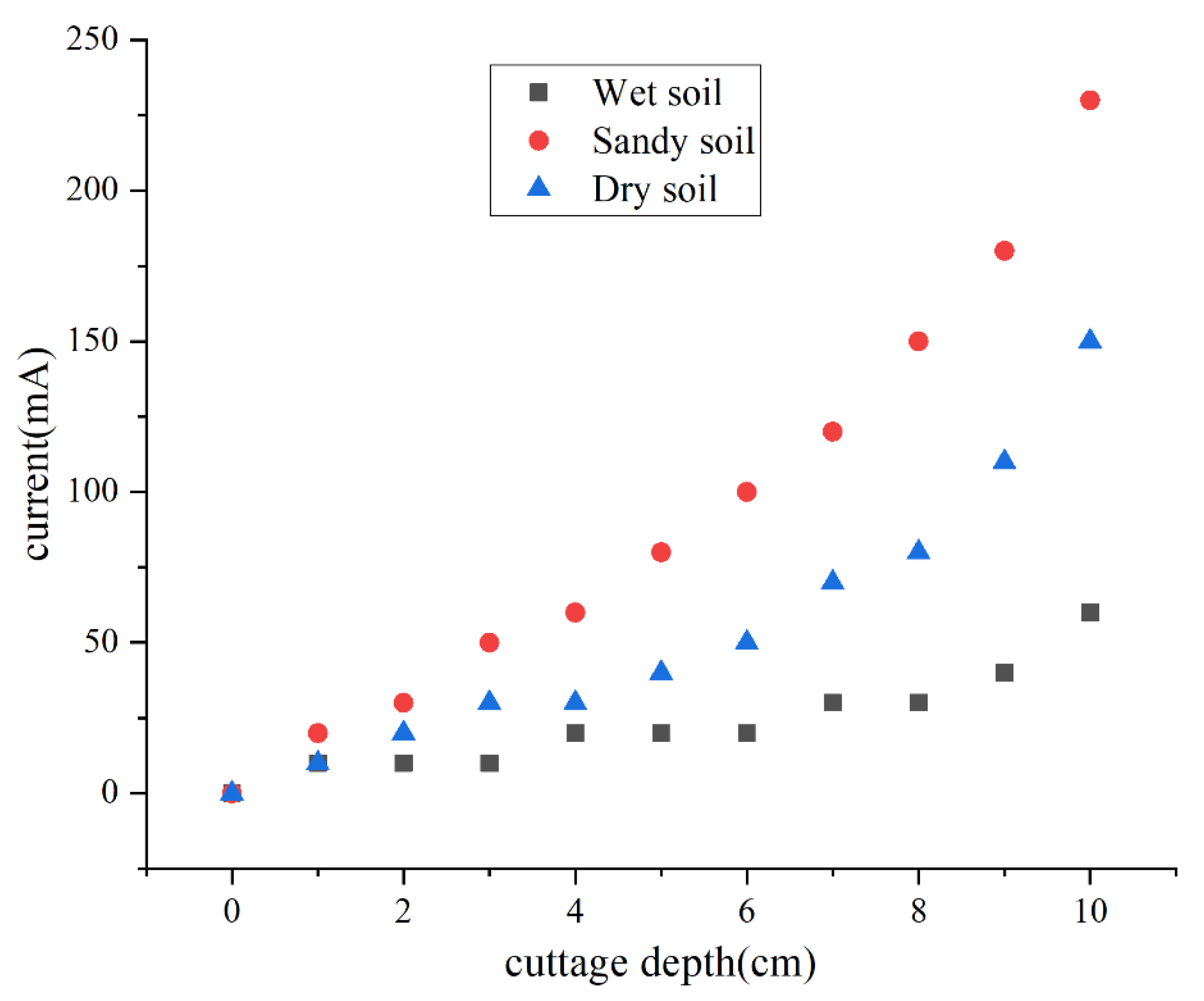
5.2.1. Verification Experiment of “Current Depth” Real-Time Feedback
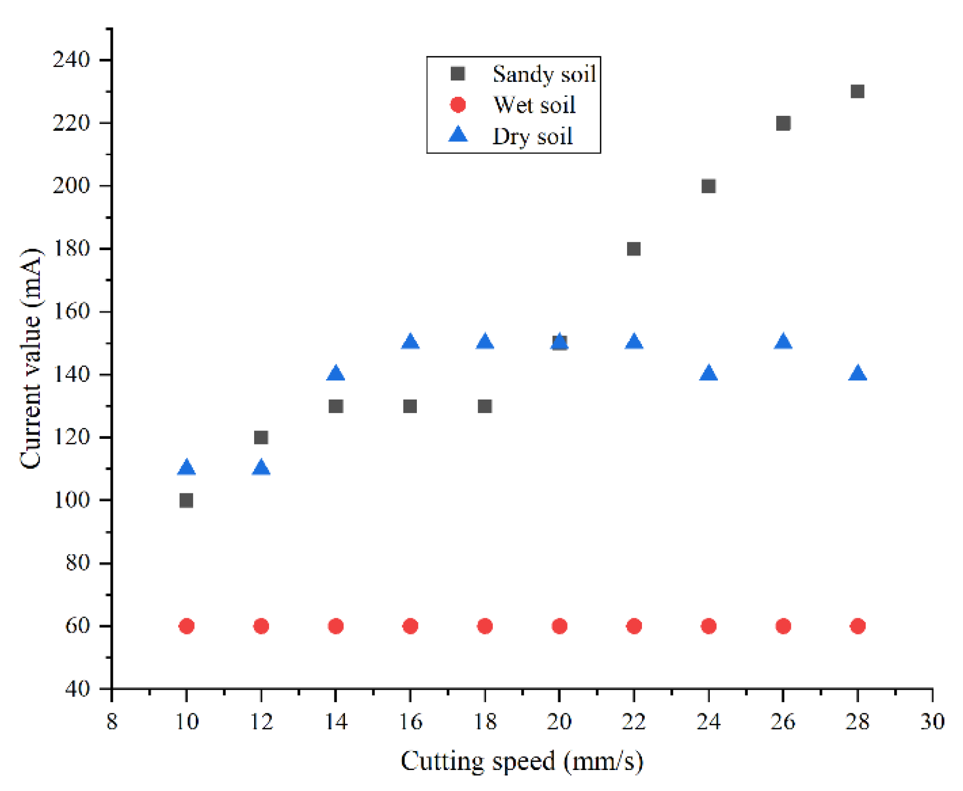
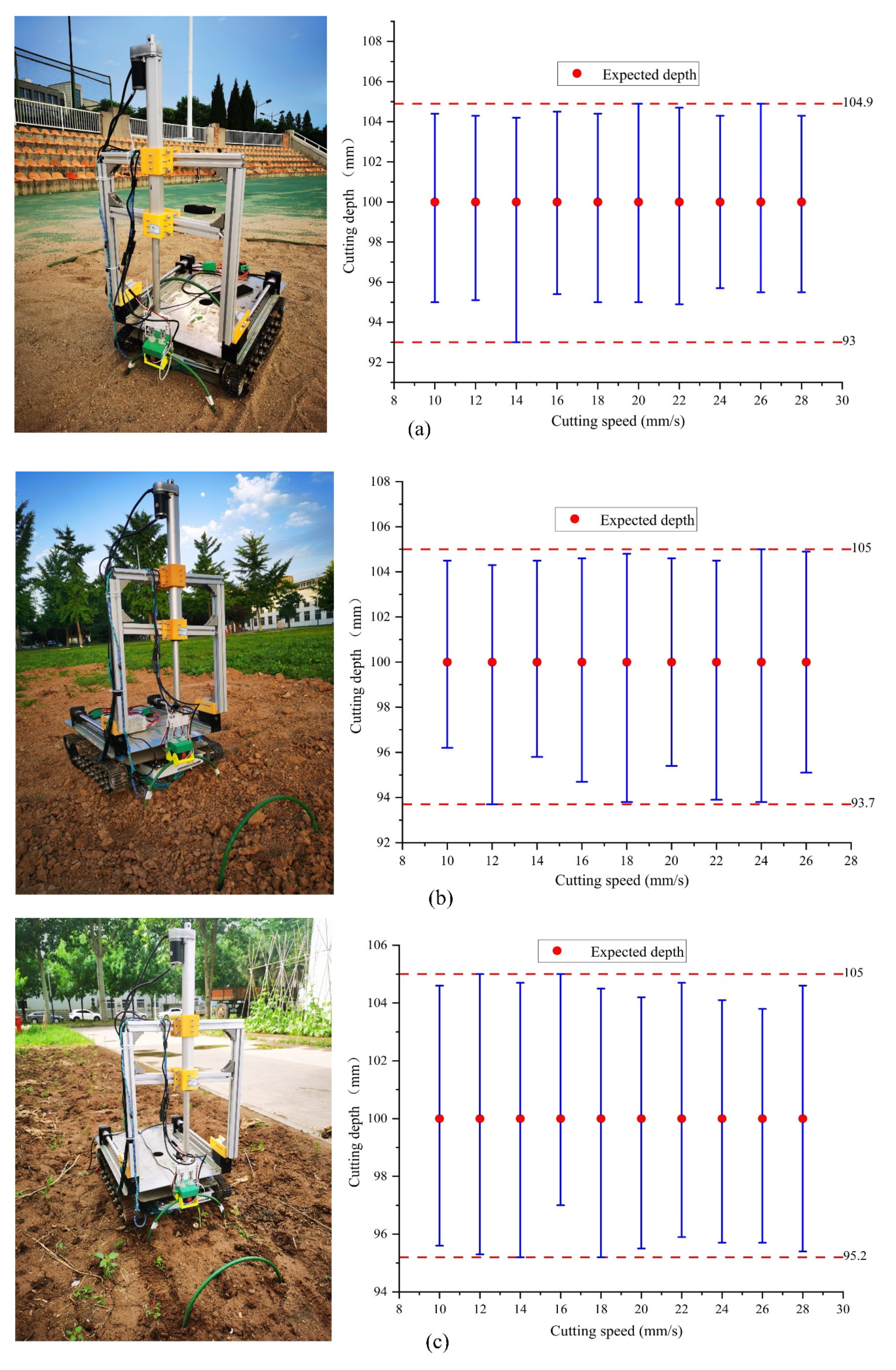
5.2.2. Determination Experiment of the Cuttage Speed
5.2.3. Error Calibration of the Cuttage Depth
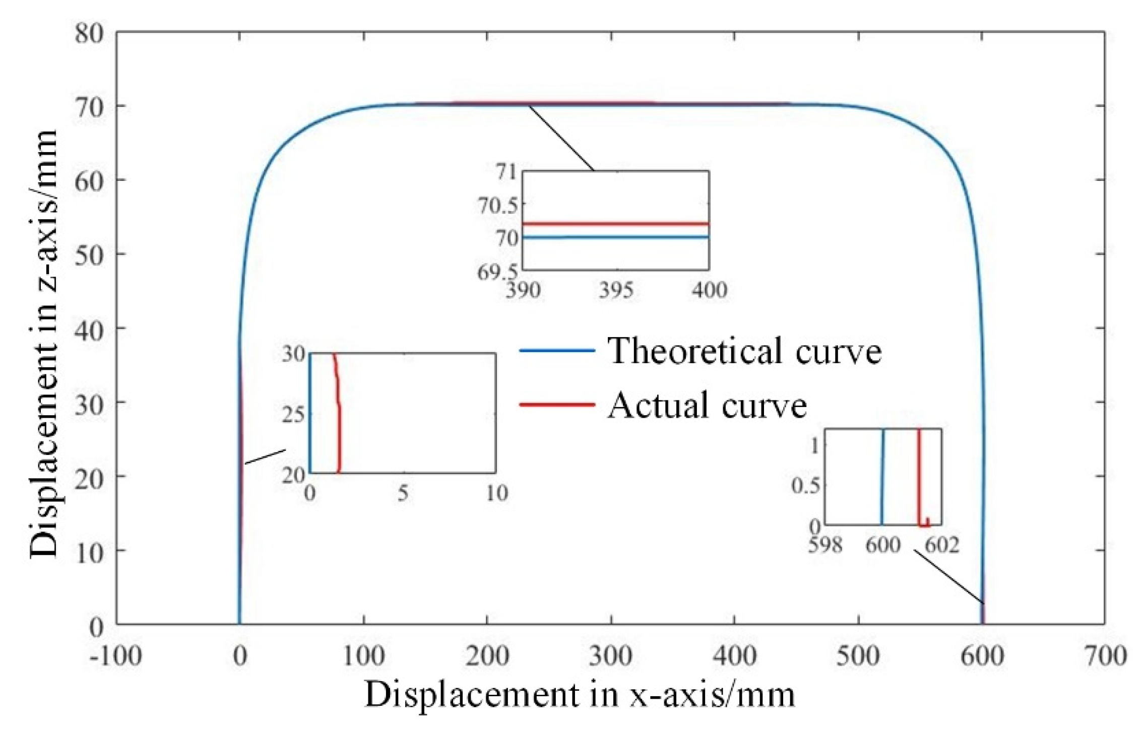
5.3. Experiment of Trajectory Planning
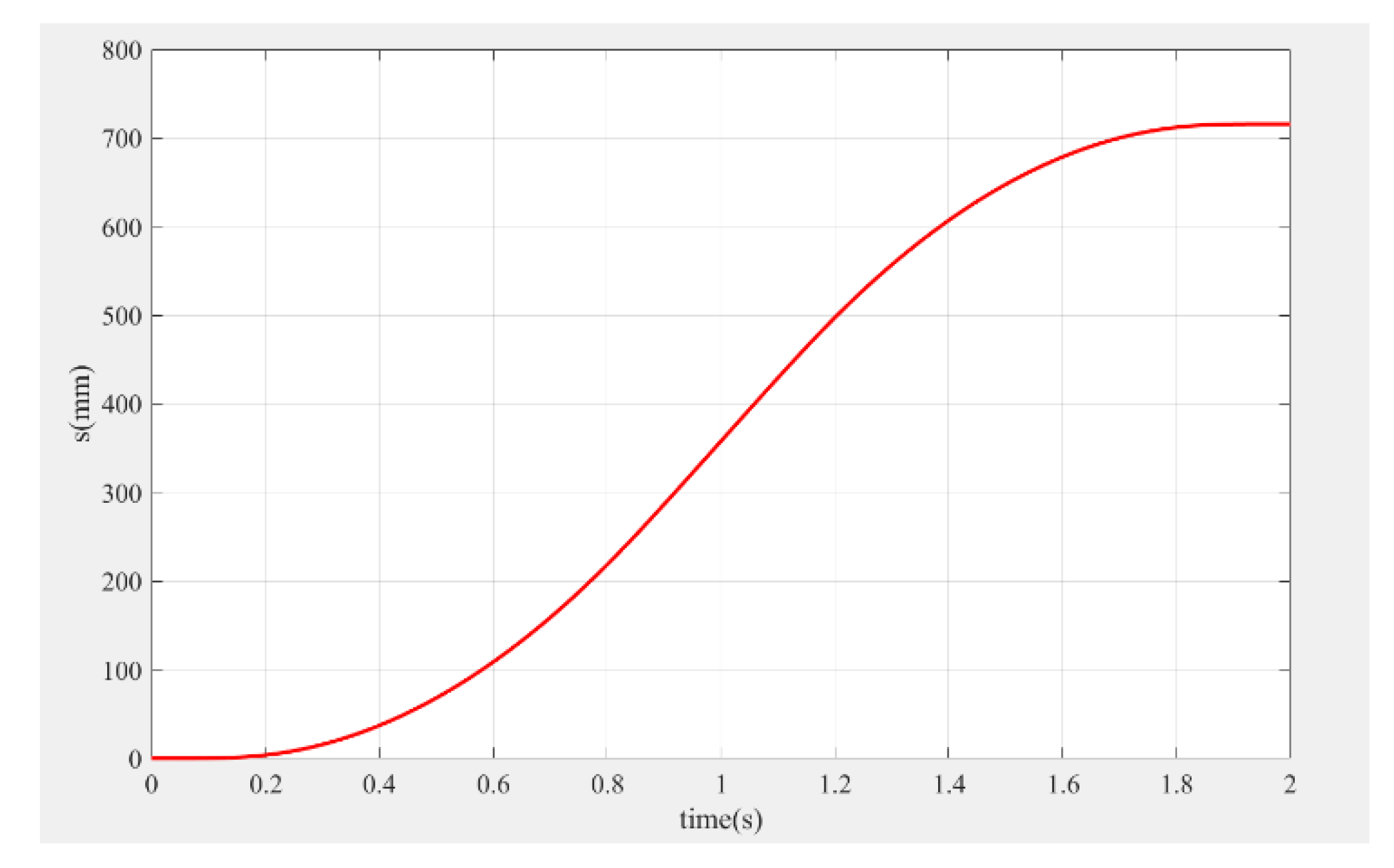
- (1)
- According to the transportation and distance lifting of the pillar, the trajectory of the execution end was planned to obtain the theoretical data, and the theoretical curve was generated using MATLAB;
- (2)
- The motion trajectory of the execution end was tracked and measured, the experiment was repeated five times, and the collected data was used to generate the actual trajectory route;
- (3)
- The coincidence degree between the theoretical calculated trajectory and the actual trajectory was compared, as shown in Figure 18.
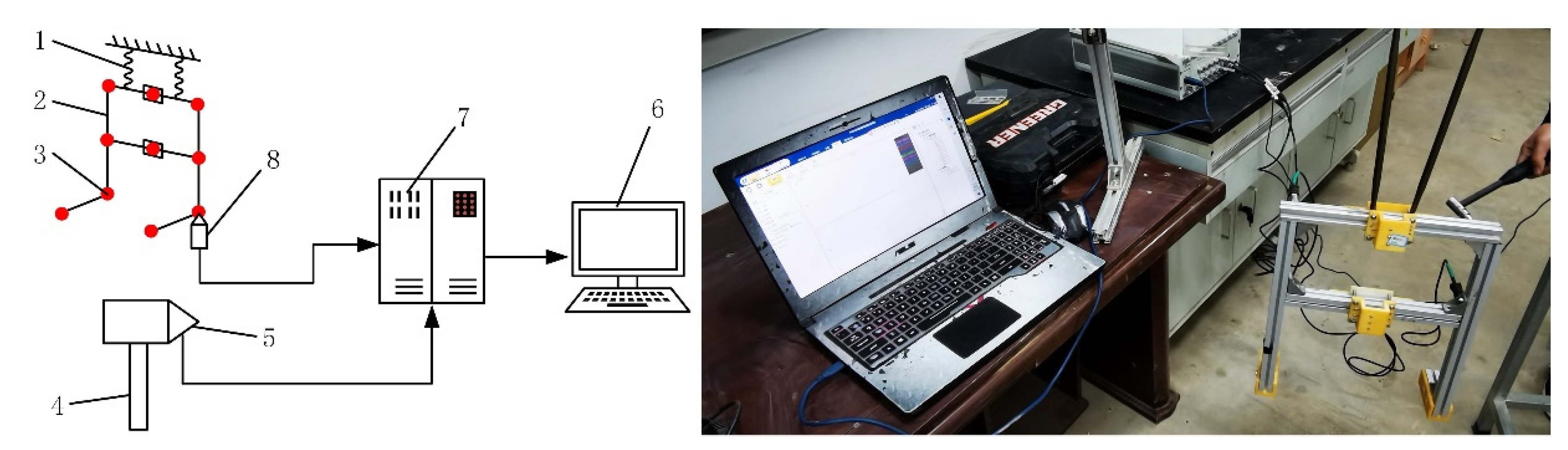
5.4. Modal Experiment Analysis
6. Conclusions
- (1)
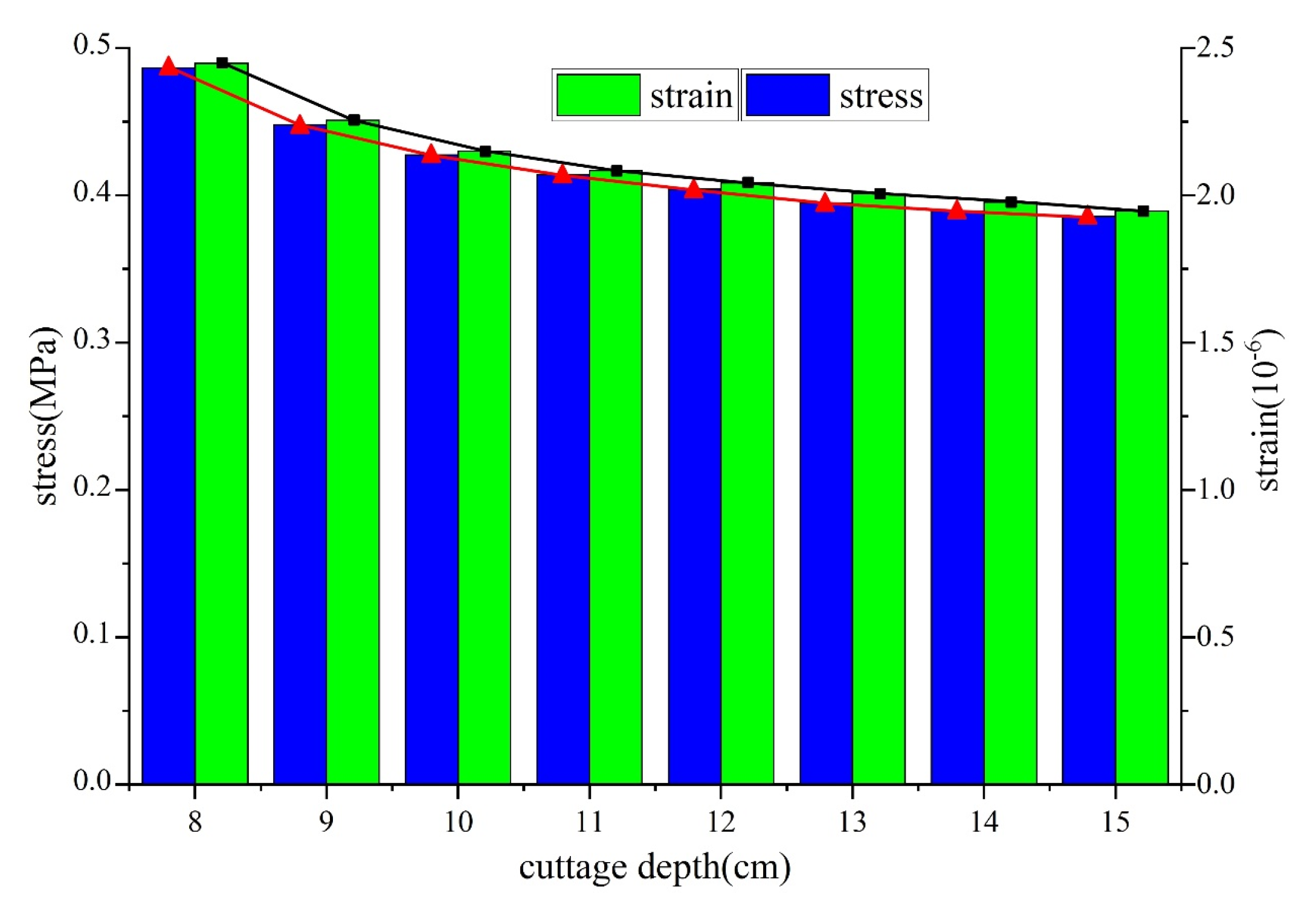
- The wind resistance of a small arch shed was analyzed. The simulation analysis by ANSYS software showed that the wind resistance was better when the cutting depth was 10 cm.
- (2)
- Three-dimensional modeling of the cuttage device was carried out through SOLIDWORKS software, the trajectory of the execution end was planned, and the relevant motion parameters were solved through MATLAB software simulation to avoid motion impact and make the motion trajectory smoother.
- (3)
- A modal analysis and experimental verification were carried out for the installation frame. The experiment showed that the resonance frequency was in the range of 303–565 Hz, and the device did not resonate during the operation.
- (4)
- A real-time feedback mechanism based on “current–force–depth” was built, which could feed back the current of the electric pusher motor in real-time. Based on this, the cutting depth was estimated in real time, allowing for the convenient building of an equal-depth pillar cuttage device. Even under the condition of the stress limit of the pillar, the automatic cutting device was able to realize “overload stop” without causing damage to the pillar, and realize the overload protection of the pillar. This could have a positive role in promoting the technical development and social application of automatic arch shed construction.
Author Contributions
Funding
Institutional Review Board Statement
Informed Consent Statement
Data Availability Statement
Conflicts of Interest
References
- Anderson, H.C.; Rogers, M.A.; Hoover, E.E. Low tunnel covering and microclimate, fruit yield, and quality in an organic strawberry production system. HortTechnology 2019, 29, 590–598. [Google Scholar] [CrossRef] [Green Version]
- Lewers, K.S.; Fleisher, D.H.; Daughtry, C.S.T.; Vinyard, B.T. Low-tunnel strawberry production: Comparison of cultivars and films. Int. J. Fruit Sci. 2020, 20, 705–732. [Google Scholar] [CrossRef]
- Henschel, J.M.; Resende, J.T.; Giloni-Lima, P.C.; Zeist, A.R.; Lima, R.B.; Santos, M.H. Production and quality of strawberry cultivated under different colors of low tunnel cover. Hortic. Bras. 2017, 35, 364–370. [Google Scholar] [CrossRef] [Green Version]
- Liu, P.; Wang, C.; Qin, H.; Hou, J.; Li, T. Design and experiment of single-row double cuttage and film covering multi-functional machine for low tunnels. Trans. Chin. Soc. Agric. Eng. 2021, 37, 1–9, (In Chinese with English Abstract). [Google Scholar]
- Liu, P.; Qin, H.; Wang, Y.; Shao, R.; Wang, Y. Design and Development of a Low Tunnel Machine. J. Agric. Mech. Res. 2021, 43, 83–89, (In Chinese with English Abstract). [Google Scholar]
- Liu, J.; Zhao, S.; Li, N.; Faheem, M.; Zhou, T.; Cai, W.; Zhao, M.; Zhu, X.; Li, P. Development and field test of an autonomous strawberry plug seeding transplanter for use in elevated cultivation. Appl. Eng. Agric. 2019, 35, 1067–1078. [Google Scholar] [CrossRef]
- Orde, K.M.; Sideman, R.G. Winter survival and second-year spring yields of day-neutral strawberry are influenced by cultivar and the presence of low tunnels. HortTechnology 2021, 31, 77–88. [Google Scholar] [CrossRef]
- Zhao, Y.; Lu, D.; Zhen, Y. Research to Enhance the Supporting Stiffness of Different U-Type Sheds. Appl. Mech. Mater. 2012, 256–259, 892–895. [Google Scholar] [CrossRef]
- Cramer, M.E.; Demchak, K.; Marini, R.; Leskey, T. UV-blocking high-tunnel plastics reduce Japanese beetle (Popillia japonica) in red raspberry. Hortscience 2019, 54, 903–909. [Google Scholar] [CrossRef] [Green Version]
- Morcous, G. Performance of Conservatories under Wind and Snow Loads. J. Archit. Eng. 2009, 15, 102–109. [Google Scholar] [CrossRef]
- Santolini, E.; Pulvirenti, B.; Torreggiani, D.; Tassinari, P. Novel methodologies for the characterization of airflow properties of shading screens by means of wind-tunnel experiments and CFD numerical modeling. Comput. Electron. Agric. 2019, 163, 104800. [Google Scholar] [CrossRef]
- Wang, C.; Jiang, Y.; Li, X.; Bai, Y.; Wang, T. Wind-induced vibration response analysis of Chinese solar greenhouses. Comput. Electron. Agric. 2021, 181, 105954. [Google Scholar] [CrossRef]
- Rack-woo, K.; Lee, I.; Kwon, K. Evaluation of wind pressure acting on multi-span greenhouses using CFD technique, Part 1: Development of the CFD model. Biosyst. Eng. 2017, 164, 257–280. [Google Scholar]
- Briassoulis, D.; Dougka, G.; Dimakogianni, D.; Vayas, I. Analysis of the collapse of a greenhouse with vaulted roof. Biosyst. Eng. 2016, 151, 495–509. [Google Scholar] [CrossRef]
- Mossadeghi-Bjorklund, M.; Jarvis, N.; Larsbo, M.; Forkman, J.; Keller, T. Effects of compaction on soil hydraulic properties, penetration resistance and water flow patterns at the soil profile scale. Soil Use Manag. 2019, 35, 367–377. [Google Scholar] [CrossRef]
- Spong, M.W. Modeling and control of elastic joint robots. J. Dyn. Syst. Meas. Control. 1987, 109, 310–319. [Google Scholar] [CrossRef]
- Chen, S.; Luo, M.; He, F. A universal algorithm for sensorless collision detection of robot actuator faults. Adv. Mech. Eng. 2018, 10, 1687814017740710. [Google Scholar] [CrossRef] [Green Version]
- Shi, Y.; Zhang, W.; Yang, T.; Wang, Y.; Liu, L.; Cui, Y. Flexible Joints of Picking Manipulator Based on Current Feedback. IEEE Access 2020, 8, 85329–85338. [Google Scholar] [CrossRef]
- Qin, H. Design and Experiment of Self-Propelled Variable-Pitch Arch Shed Inserting Laminator. Master’s Thesis, Shandong Agricultural University, Tai’an, China, 2020. [Google Scholar]
- China Radio Network. Available online: http://www.cnr.cn/ (accessed on 11 January 2019).
- Mistriotis, A.; Castellno, S. Aiflow through net covered tunnel structures at high wind speeds. Biosyst. Eng. 2012, 113, 308–317. [Google Scholar] [CrossRef]
- Guan, Y.; Zheng, F.; Zhang, P.; Qin, C. Spatial and temporal changes of meteorological disasters in China during 1950–2013. Nat. Hazards 2015, 3, 2607–2623. [Google Scholar] [CrossRef]
- Huai, B.; Wang, Y.; Sun, W.; Wang, X.Y. The unique “Regional East Gale with Blowing Snow” natural disaster in Jeminay County, Xinjiang Uygur Autonomous Region, China. Nat. Hazards 2018, 2, 1105–1108. [Google Scholar]
- Yasushi, U.; Kazuya, T. Collapse and reinforcement of pipe-framed greenhouse under static wind loading. J. Civ. Eng. Archit. 2020, 14, 583–594. [Google Scholar] [CrossRef]
- Shaanxi Meteorological Bureau. Available online: https://sn.cma.gov.cn/ (accessed on 2 May 2021).
- Kim, R.W.; Lee, I.B.; Yeo, U.H.; Lee, S.Y. Evaluation of various national greenhouse design standards for wind loading. Biosyst. Eng. 2019, 188, 136–154. [Google Scholar] [CrossRef]
- Xie, X.; Chen, K. Simulation test of wind load characteristics of South China type single-span plastic greenhouse. Trans. Chin. Soc. Agric. Eng. 2000, 16, 90–94, (in Chinese with English abstract). [Google Scholar]
- Shi, J.; Li, T. New method to eliminate commutation torque ripple of brushless dc motor with minimum commutation time. IEEE Trans. Ind. Electron. 2013, 60, 2139–2146. [Google Scholar] [CrossRef]
- Carlson, R.; Lajoiemazenc, M.; Fagundes, J. Analysis of torque ripple due to phase commutation in brushless DC machines. IEEE Trans. Ind. Appl. 1992, 28, 632–638. [Google Scholar] [CrossRef]
- Lin, J.; Sun, Y.; Lammers, P.S. Evaluating model-based relationship of cone index, soil water content and bulk density using dual-sensor penetrometer data. Soil Tillage Res. 2014, 138, 9–16. [Google Scholar] [CrossRef]
- Gauthier, J.F.; Angeles, J.; Nokleby, S. Optimization of a Test Trajectory for Scara Systems; Springer: Berlin, Germany, 2008; pp. 225–234. [Google Scholar]
- Barnard, C.; Briot, S.; Caro, S. 2012 Trajectory generation for high speed pick and place robots. In Proceedings of the ASME 2012 11th Biennial Conference on Engineering Systems Design and Analysis, American Society of Mechanical Engineers, Nantes, France, 2–4 July 2012; pp. 165–174. [Google Scholar]
- Bin, Z.F.; Ong, Z.C.; Khoo, S.Y. A review of operational modal analysis techniques for in-service modal identification. J. Braz. Soc. Mech. Sci. Eng. 2020, 42, 398. [Google Scholar]
- Jiang, X.; Jiang, F. Operational modal analysis using symbolic regression for a nonlinear vibration system. J. Low Freq. Noise Vib. Act. Control. 2021, 40, 120–134. [Google Scholar] [CrossRef] [Green Version]
- Pintelon, R.; Guillaume, P.; Schoukens, J. Uncertainty calculation in (operational) modal analysis. Mech. Syst. Signal Process. 2007, 21, 2359–2373. [Google Scholar] [CrossRef]
- Wang, Y.; Pan, J. Applications of Operational Modal Analysis to a Single-Phase Distribution Transformer. IEEE Trans. Power Deliv. 2015, 30, 2061–2063. [Google Scholar] [CrossRef]
- Yao, Y.; Du, Y.; Zhu, Z.; Mao, E.; Song, Z. Vibration characteristics analysis and optimization of corn combine harvester frame using modal analysis method. Trans. Chin. Soc. Agric. Eng. 2015, 31, 46–53. [Google Scholar]


| Soil Type | Moisture Content (%) | Soil Firmness at Different Depths (kPa) | ||||
|---|---|---|---|---|---|---|
| 2.5 cm | 5 cm | 7.5 cm | 10 cm | 12.5 cm | ||
| Sandy soil | 3.25 | 291.00 | 747.71 | 1604.43 | 1818.14 | 2141.29 |
| Dry soil | 19.37 | 162.17 | 544.33 | 720.17 | 1141.50 | 1800.17 |
| Wet soil | 37.84 | 159.20 | 427.40 | 606.20 | 622.80 | 725.00 |
| Order | Frequency | Vibration Shape | Frequency of Error | ||
|---|---|---|---|---|---|
| Modal Finite Element Analysis (Hz) | Modal Test Analysis (Hz) | Modal Finite Element Analysis | Modal Test Analysis | ||
| 1 | 303.47 | 296.58 | bending | bending | 2.32% |
| 2 | 441.18 | 443.94 | bending | bending | −0.62% |
| 3 | 500.69 | 506.72 | bending + torsion | bending + torsion | −1.19% |
| 4 | 564.62 | 554.53 | bending + torsion | bending + torsion | 1.82% |
Publisher’s Note: MDPI stays neutral with regard to jurisdictional claims in published maps and institutional affiliations. |
© 2022 by the authors. Licensee MDPI, Basel, Switzerland. This article is an open access article distributed under the terms and conditions of the Creative Commons Attribution (CC BY) license (https://creativecommons.org/licenses/by/4.0/).
Share and Cite
Chen, K.; Liu, X.; Jin, S.; Li, L.; He, X.; Wang, T.; Mi, G.; Shi, Y.; Li, W. Design of and Experiments with an Automatic Cuttage Device for an Arch Shed Pillar with Force Feedback. Agriculture 2022, 12, 875. https://doi.org/10.3390/agriculture12060875
Chen K, Liu X, Jin S, Li L, He X, Wang T, Mi G, Shi Y, Li W. Design of and Experiments with an Automatic Cuttage Device for an Arch Shed Pillar with Force Feedback. Agriculture. 2022; 12(6):875. https://doi.org/10.3390/agriculture12060875
Chicago/Turabian StyleChen, Kezhou, Xing Liu, Shiteng Jin, Longfei Li, Xin He, Tao Wang, Guopeng Mi, Yinggang Shi, and Wei Li. 2022. "Design of and Experiments with an Automatic Cuttage Device for an Arch Shed Pillar with Force Feedback" Agriculture 12, no. 6: 875. https://doi.org/10.3390/agriculture12060875
APA StyleChen, K., Liu, X., Jin, S., Li, L., He, X., Wang, T., Mi, G., Shi, Y., & Li, W. (2022). Design of and Experiments with an Automatic Cuttage Device for an Arch Shed Pillar with Force Feedback. Agriculture, 12(6), 875. https://doi.org/10.3390/agriculture12060875