Article

The Method of Calculating Ploughshares Durability in Agricultural Machines Verified on Plasma-Hardened Parts

by
Alexandr Gulyarenko
1 and
Michał Bembenek
2,*
1
Faculty of Technology, S. Seifullin Kazakh Agro Technical University, A. Moldagulova Street, 29a-302, Nur-Sultan 010000, Kazakhstan
2
Faculty of Mechanical Engineering and Robotics, AGH University of Science and Technology, A. Mickiewicza 30, 30-059 Kraków, Poland
*
Author to whom correspondence should be addressed.
Agriculture 2022, 12(6), 841; https://doi.org/10.3390/agriculture12060841
Submission received: 22 May 2022 / Revised: 8 June 2022 / Accepted: 9 June 2022 / Published: 10 June 2022
(This article belongs to the Special Issue Design and Application of Agricultural Equipment in Tillage System)

Abstract

:
Reliability consists of four components: failure-less operation, maintainability, durability, and preservation ability. For different machines and different conditions of operation, different combinations of these properties, and differences in how they are balanced and proportioned are essential. For tractors, the most important aspect of reliability is maintainability, while for agricultural machines, durability is most important. Using the example of a ploughshare, the issue of increasing the durability has been studied; a method for calculating the durability of a ploughshare for various types of soils has been described. The use of plasma hardening of the surface of a 65G-steel ploughshare has been proposed; the effectiveness of plasma hardening of soil-cutting parts and its economic feasibility have been proved. Due to hardening to a depth of 1–1.8 mm, the service life of parts increases by 2–3 times; moreover the downtime of expensive machine-tractor units for replacing worn-out parts is reduced.

1. Introduction

The applied and economic significance of the development of agriculture is obvious. The food security of the country depends on it. Nowadays, the leading positions in the development of agriculture are held by China, India, and the United States [1]. At the same time, the basis of agriculture is crop production. In turn, the profitability of crop production largely depends on the efficiency of using machine-tractor units (MTU). Modern high-performance and high-tech MTUs are the primary tool for crop production. The effectiveness of using MTUs depends on a large number of factors. However, no matter how powerful and technological they are, the effectiveness of their use is primarily determined by their reliability. At the same time, the MTU consists of two main parts, the tractor and the process machine; therefore, it is evident that the reliability of the MTU comprises two components, i.e., the reliability of the tractor and the reliability of the process machine. So, in this case, the reliability components will not have the same effect on the tractor and the process machine. For a tractor, the principal factors influencing the efficiency of use are the reliability components, i.e., reliability and maintainability. Their influence on the efficiency of using MTUs and ways of managing the reliability indicators of tractors have already been investigated, and recommendations have already been given for equipping MTUs with tractors of different levels of reliability [2,3,4,5,6,7,8].
To solve the issue of increasing the efficiency of using MTUs in a comprehensive way, it is necessary to investigate the issue of increasing the reliability of the process machine. Soil-cutting machines will be considered process machines in this study, since they perform the leading and most energy-consuming operations in crop production [9,10,11].
The most important aspect of improving the technical level of soil-cutting machines is considered to be increasing the service life of their tools [9,10,11,12,13,14,15,16]. In this case, it is the indicators of durability that will be of paramount importance [17,18,19,20,21]. Since it is the durability of the tools of the process machine that will affect the machine-tractor unit as a whole, the very durability of the soil-cutters will have a significant impact on the increase in energy costs (fuel consumption), the observance of agrotechnical requirements (yield), and even the reliability of the tractor itself [22,23]. Therefore, the qualitative increase in these indicators can be achieved only by identifying the main reason for their decrease. In this case, both a tractor and an agricultural machine are needed to perform a process operation, and if this operation is cutting the soil with a tool, then, accordingly, the most obvious way to qualitatively improve the indicators is to study the cutting process and its optimisation [24,25,26]. As a result of intense abrasive wear, the geometry of the cutting part and the overall dimensions of the tools change [27,28,29], and therefore it is necessary to increase the hardness of the working bodies using various methods of hardening [30,31,32,33,34,35,36,37], and, at the same time, to develop reliable methods for calculating durability [38,39].
Thus, our study combines three key aspects:
1. The relevance of work for agriculture, in particular, for crop production, since the forced frequent replacement of parts of the working bodies leads to a decrease in labour productivity and an increase in processing costs [40,41,42]. For example, as calculations show, based on the existing resources and the prices of parts of the plough tools, every 100 hectares of ploughing required monetary costs of at least USD 70 only for their replacement and at least four person-hours of labour costs. These figures reach about USD 85 million in Kazakhstan and an additional need for about three thousand machine operators. Therefore, the relationship between durability and maintainability is also obvious, i.e., the less durable the machine, the higher its maintainability should be since frequent replacements of tools require labour and time, which again leads to costs and non-compliance with agrotechnical requirements.
2. The proposed method for calculating the durability of the ploughshares will allow the durability of the share for different types of soil and different hardness of the plow surface to be calculated. In the existing methods, the nominal parameters of the ploughshares are used in the calculations and only soil indicators vary [19,43,44,45,46].
In addition, studies into the hardness of the ploughshare surface (operational control by ultrasonic method, depth measurement and structure analysis), as well as field comparative tests of hardened and nominal ploughs in identical conditions (installed on the same unit) will confirm the correctness of the durability calculation method and predict the resource of the plough share in surface hardness and soil type.
3. The proposed method of manual plasma hardening has a number of advantages in comparison with existing hardening methods. One example of this is the method used in the USA for argon-arc surfacing of petrochemical fittings with hard-alloy stellite [47]. Due to its brittleness, this cobalt alloy cannot be drawn into a wire, so continuous feeding into the arc is carried out only by blowing it in the form of a powder. However, the powder, when injected, scatters, deposited on the tip of the tungsten electrode, and quickly disables it. These problems are being solved, and stellites and methods of their application are still being improved, but in our opinion, any methods of spraying or surfacing cannot be used in this case, since an increase in thickness inevitably leads to an increase in the resistance of the soil-cutting organ, and this is, again, a violation of agricultural requirements, increased load, breakdowns, excessive fuel consumption, etc. At the same time, there are a large number of hardening methods precisely due to spraying and surfacing [20,48,49,50]. This direction is still relevant and has been developing since the first half of the 20th century; however, the main disadvantage of these methods has been and will be the consumption of the sprayed or deposited substance. The high cost of these hardening methods and the increase in the thickness of soil-cutting methods make them unacceptable for our study. At the same time, there are methods for hardening parts, but they are also not acceptable, since when a fully hardened part becomes hard, at the same time, it becomes too brittle [51]. Due to the heterogeneity of the soil, chips appear, while excessively plastic parts undergo plastic deformation, while wear also increases. Thus, to solve our problem, a hardening method is required that allows the hardness of the surface layer of the metal to be increased, and at the same time, allows the elasticity and plasticity of the soil-cutting part to be maintained, and all without increasing the thickness.
Consequently, reliability is paramount for a tractor, and durability is paramount for a process machine, and only after that, comes maintainability in the case of breakdown or wear. In this regard, the issue of the development and production of high-quality and long-life soil-cutters, ensuring compliance with agrotechnical requirements during treatment, which are long-living and competitive in terms of their cost, is quite acute. The method of calculating the durability of the plough blade presented in the article will make it possible to make comparative calculations of durability for different types of soil [14,18,19,52,53,54,55,56,57]. Moreover, the method of plasma hardening [58,59,60,61,62,63,64,65,66] of soil-cutting working bodies used by us will increase the durability of the plough compared to serial samples and experimentally confirm the correctness of the calculations.

2. Material and Methods

2.1. Calculation Methodology Model

In the general case, the service life of the tools can be represented as a function of the following main varying parameters:
T = f (I, m, p, ν, η1, η2ηn)
where T is the service life, h (ha); I is the wear resistance of the tool material, h/g (h/mm); m is the wear capacity of the soil, g/h (mm/h); p is the soil pressure on the working surface of the tool, MPa; ν is the speed of movement of the tool relative to the soil, km/h; and η1, η2ηn are the factors characterising the change in the main parameters depending on the condition of the soil, the composition of the material of the tools, and the modes of their heat treatment, the design parameters of the tools, etc.
It is possible to manage the service life of the tools if the general pattern of ensuring their performance and the nature of wear in the soil are known. Many papers are devoted to the establishment of such patterns and the development of recommendations for determining the intensity of wear and predicting the service life of tools. However, their practical application is constrained because they do not fully take into account those complex dependencies that exist in the process of abrasive wear. Notably, it was revealed that the relative wear resistance of materials and the wear capacity of the abrasive medium (soil) are not constant values. They vary depending on the pressure of the abrasive medium on the tool. The lack of a reasonably simple methodology for determining the wear rate and the service life of tools hinders the development and justification of using new materials and technologies when hardening tools to increase their service life. These circumstances have led to the fact that modern ploughs today use ploughshares, the design parameters and materials developed more than 40 years ago. However, their operation modes have changed significantly, i.e., the processing speed, the weight of the machines, and, consequently, and the compaction of soils within the processing period, especially when harvesting, have all increased. All this leads to an increase in the load on the tools and, accordingly, their wear rate.
A characteristic feature of the soil-cutting tools is a relatively large area of contact with the cultivated soil. In this case, the loads on individual sections of the working surface differ significantly. For example, the ploughshare has the most significant pressure on the tip and significantly less pressure on the blade. In this regard, the wear rate of different sections is not the same. Consequently, the tools are rejected due to the wear rate on one relatively small section, while the rest of the sections have a significant residual life.
Let us consider the methodology for predicting the service life on the example of a ploughshare, depending on the types of soils, materials of which it is made and which are used to harden it, and changes in some design parameters.
The intensity of wear of tools has been studied in the field, and research materials of other authors have been used [12,13,14,15,19]. Consequently, a mathematical expression of the abrasive wear rate of the tools has been developed, depending on several parameters. In the general case, wear rate, cm, of the most wear-prone section is calculated as follows:
W = k r e f   m     η 1     p     v p     t ε r e f   η 2   χ
where kref is the factor of proportionality of the wear of the reference sample under reference conditions: kref = 0.016 cm/(MPa·km); m is the relative wear capacity of the soil (in terms of particle size distribution) at the reference pressure of the abrasive medium (quartz); η1 is the factor that takes into account the change in the relative wear capacity of the soil depending on pressure; p is the pressure of the soil (abrasive medium) on the most wear-prone section of the tool, MPa; vp is the forward speed of the tool, km/h; t is the operating time of the tool, h; εref is the relative wear resistance of the material under reference test conditions; η2 is the factor that takes into account the change in the relative wear resistance of the material depending on the pressure; and χ is the ratio of the speed of movement of the soil layer on the surface of the tool to the speed of the tool.
The following formula can determine the durability, h, of the tool:
T = W c r i t   ε r e f   η 2   χ k r e f     m     η 1     p     v p
where Wcrit is the limiting wear rate of the most wear-prone section of the tool, cm.
Steel 45 with a hardness of 90 HRB (or 180 HB) is taken as reference material. The following are taken as reference wear conditions: pressure pref = 0.1 MPa; abrasive medium is quartz particles with a size of 0.16÷0.32 microns; relative wear capacity of the abrasive medium m = 1; vp = 1 km/h.
The values of the relative wear capacity of soils are given in Table 1.
The dependence of the relative wear resistance of steels, of which the tools of soil-cutting machines are made, on their chemical composition and hardness is presented in the form of an empirical equation [16]:
ε = 0.24X1 + 0.07X2 + 0.11X3 − 3.54,
where ε is the relative wear resistance of steel (the standard is steel 45 with a hardness of 90 HRB, the abrasive medium is quartz with particles of 0.16 ÷ 0.32 microns in size, the pressure of the abrasive medium is p = 0.33 MPa); X1 is carbon content, %; X2 is chromium content, %; and X3 is hardness, HRC.
Permanent alloying elements in raw, untreated steels, manganese and silicon, have a positive effect on some characteristics of steels but not on their wear resistance [67,68,69]. The content of elements such as tungsten, molybdenum, and vanadium in steels increases wear resistance above 60 HRC. At lower hardness, their effect on wear resistance is minor [9,30,31,32].
Therefore, these elements are not included in the equation. The following empirical formulas determine the values of the correction factors η1 and η2:
η1 = 9.6p − 0.04
η2 = 1.75p + 0.825
If the value of the relative wear resistance of steel at the reference pressure is unknown, then it is determined by the following formula:
ε r e f = ε η 2
where ε is the relative wear resistance of steel at a pressure of p = 0.33 MPa (see Equation (4)).
Considering that the load on the ploughshare tip and the intensity of its wear vary significantly from the exact parameters of the blade, the durability of the ploughshare is calculated according to two criteria, i.e., wear rate of the tip and wear rate of the blade.
The permissible wear rate of the tip is determined by the difference between the original H (Figure 1) and the limiting, Hcrit, tip height. The permissible wear rate of the blade is also determined by the difference between the initial, h, and the permissible, hcrit, blade width or the proper blade thickness, a.
The durability of the share according to the cultivated area in hectares (ha), according to the wear of the tip:
T t i p = ε r e f   η 2   χ   A   ( H H c r i t ) k r e f     m     η 1     p     v p
where A is the performance of the plough body, ha/h; H-Hcrit is the limiting wear rate of the tip in height, cm.
The durability of the ploughshare, ha, according to the wear rate of the blade:
T b l a = ε r e f   η 2   χ   A   ( h h c r i t ) k r e f     m     η 1     p     v p
where hhcrit is the limiting wear rate of the blade in width, cm.
In most cases, the ploughshares are rejected not as per the wear rate of the blade in width but as per the limiting thickness of the blade.
The durability of the ploughshare blade as per the limiting thickness:
T b l a = ( a b ) ε r e f   η 2   χ   A k r e f     m     η 1     p     v p     tan α
where a is the limiting thickness of the ploughshare blade for specific ploughing conditions, cm; b is the initial thickness of the new ploughshare blade, cm; α is the angle of sharpening the ploughshare.
As can be seen from Equations (8)–(10), the durability of the ploughshare is directly proportional to the relative wear resistance of the material. It is inversely proportional to the wear capacity of the soil, the pressure of the abrasive medium, the speed of the plough, and the angle of sharpening the blade. The larger the sharpening angle, the faster the blade will reach its limiting thickness and will be rejected due to its poor penetration.
The maximum total pressures acting on the tip and the blade of the ploughshare can be determined by the following empirical relationships [19,70]:
p b l a = ( 0.012 ÷ 0.016 ) ( 1 + 0.028 v p ) ( 1 + 0.01 β ) ( 1.45 + H + 0.5 H 1.5 )
p t i p = ( 0.06 ÷ 0.065 ) ( 1 + 0.028 v p ) ( 1 + 0.01 β ) ( 1.45 + H + 0.5 H 1.5 )
where p b l a is the pressure on the ploughshare blade, MPa; p t i p is the pressure on the ploughshare tip, MPa; v p is the speed of movement of the tool, km/h; β is the angle of inclination of the ploughshare to the bottom of the furrow, °; and H is the soil hardness, MPa.
The proper thickness (mm) of the ploughshare blade, at which a constant ploughing depth is provided, can be determined by the following empirical equation:
a = 8 H
For example, the durability of a serial 65G steel ploughshare without additional hardening will we calculated.
The calculation will be carried out using the following ploughing conditions:
-
Types of soils: sandy, light-loamy, and light-clayey;
-
Soil hardness: H = 1 MPa , H = 3 MPa , H = 5 MPa ;
-
Ploughing speed: v p = 10 km/h;
-
Performance of the plough body: A = 0.35 ha/h;
-
The angle of inclination of the ploughshare to the bottom of the furrow, β = 30°.
Serial ploughshare parameters:
-
Relative wear resistance, ε = 1.28 for 65G steel and at the reference pressure of the abrasive medium;
-
Original tip blade thickness, b = 2 mm;
-
Limiting wear rate of the tip in height, H c r i t = 6.8 cm ;
-
Limiting blade thickness at H = 5 MPa , a = 3 mm; at H = 3 MPa, a = 5 mm; at H = 1 MPa, a = 7 mm.
The 7 mm limitation of the blade thickness is due to the limitation of the ploughshare wear rate in width; and blade sharpening angle, α = 8°.
The calculation results are shown in Table 2.
According to the data in Table 2, the service life of serial ploughshares varies from 2.06 to 9.83 ha on sandy soils (depending on their hardness). With a hardness of 5 MPa, the ploughshares will be rejected according to the maximum thickness of the blade. The service life of the tip is greater than that of the blade. To increase the service life of the blade, for example, to 2.95 ha, its sharpening angle should be reduced. Consequently, the potential for blade wear rate is increased without compromising ploughshare performance.
With a sandy soil hardness of 3 MPa, the service lives of the tip and the blades are 4.85 and 4.6 ha, respectively. That is, the ploughshare is subject to wear almost evenly.
On loamy soils with a hardness of 5 MPa, the service life of the tip exceeds the service life of the blade. The ploughshare will be rejected because it is out of plough. With a soil hardness of 3 MPa, the service lives of the tip and the blade are equal to 10.1 ha. That is, the ploughshare is subject to wear evenly. With a hardness of 1 MPa on loamy soils, the service life of a serial ploughshare is 20.7 ha. In this case, the tip is primarily exposed to wear. The residual life of the blade when rejecting the ploughshare will be about 40 ha.
On clay soils, the service life of the serial ploughshare, depending on the hardness of the soil, will vary from 12.5 ha with a hardness of 5 MPa to 58.8 ha with a hardness of 1 MPa. In the latter case, when the ploughshare is rejected, its blade will be underutilised by about 100 ha of ploughing, i.e., by hardening the tip part, the ploughshare service life of about 160 ha can be achieved.
As practice shows in most cases, the hardness of sandy and light loamy soils at a depth of 20 ÷ 30 cm is 2.2 ÷ 2.8 MPa. This means that the service life of ploughshares made of 65G steel without hardening for such soils will be 7 ÷ 14 ha. By hardening the tip of these ploughshares only, it is possible to bring their service life up to 26 ÷ 36 ha, respectively. Therefore, by hardening the tip of a 65G steel ploughshare using plasma hardening, it is possible to achieve at least a 2.6-fold increase in its service life compared to a non-hardened serial ploughshare. When ploughing medium and heavy loamy soils, the difference in the service lives of serial and test ploughshares will be much more significant.
Let us consider the possibilities of increasing the durability of the ploughshare by hardening the tip, the blade, or both, proceeding from ensuring their equal wear resistance. In the general case, to ensure equal wear resistance of the blade and the tip of the ploughshare, the required relative wear resistance can be determined based on the equality of the durability:
  ( H H c r i t ) ε r e f t i p   η 2 t i p η 1 t i p p t i p = ( a b ) ε r e f b l a   η 2 b l a η 1 b l a p b l a tan α
where from:
ε r e f t i p = ( a b ) ε r e f b l a   η 2 b l a η 1 t i p p t i p ( H H c r i t ) η 2 t i p η 1 b l a p b l a tan α
where ε r e f t i p and ε r e f b l a are the relative wear resistance of the tip and the blade, respectively; η 1 t i p and η 1 b l a are correction factors that take into account the change in the wear capacity of soils, respectively, on the tip and the blade; η 2 t i p and η 2 b l a are correction factors that take into account the change in the relative wear resistance of materials, respectively, of the tip and the blade; and p t i p and p b l a are soil pressure on the tip and the blade, respectively.

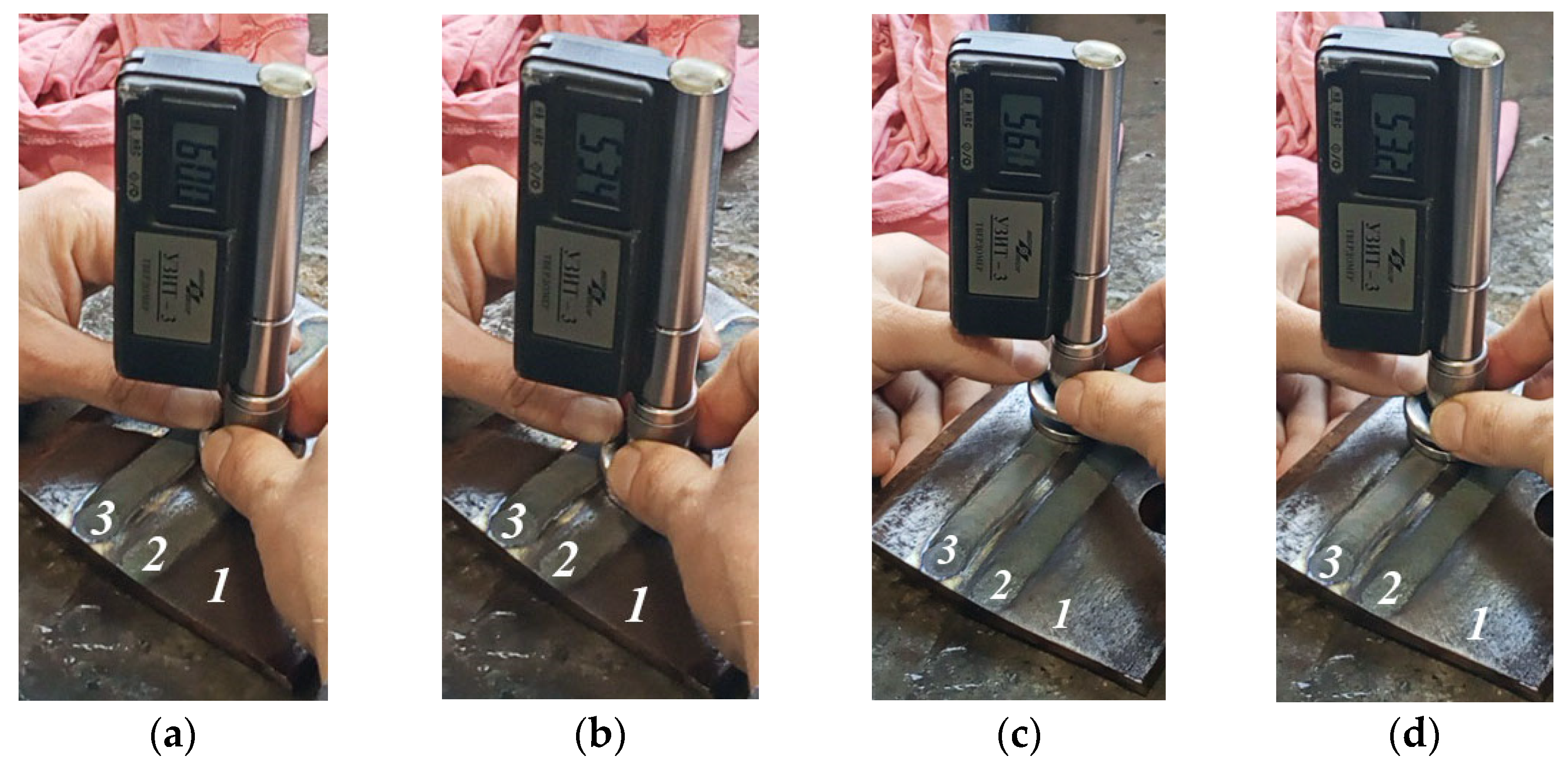
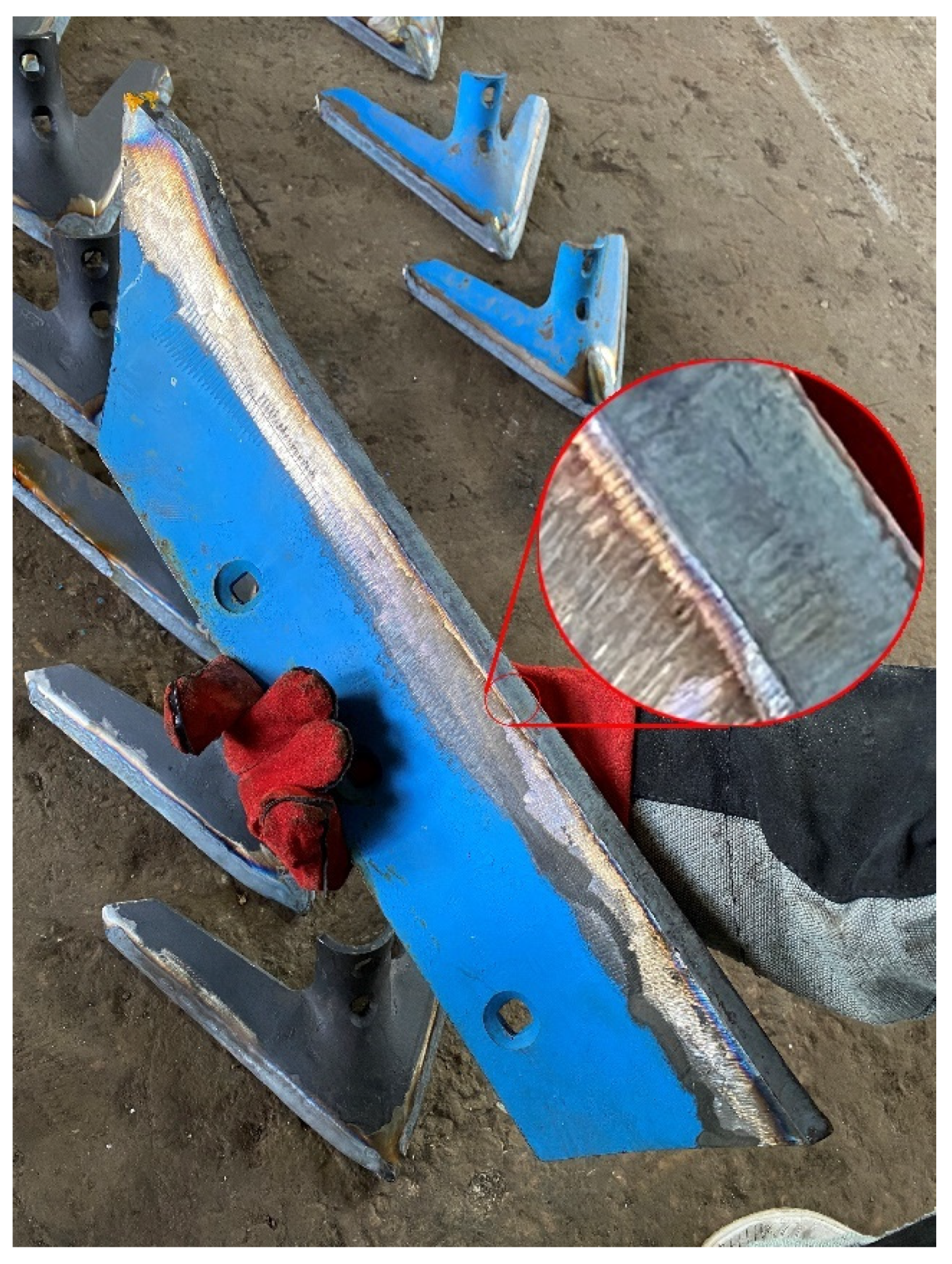
2.2. Methods of Confirming the Results of Calculations by Experiment

Experience shows that the hardening of structural steels to such a depth is achievable using surface plasma treatment (hardening) technology. Let us also note that to ensure tribotechnical properties (increase in wear resistance and decrease in the friction coefficient), which provide the required durability of the parts in the friction units, the thickness of the hardened layer of over 1.0–1.8 mm is not required. Since only the friction surface is subject to wear, in this case, as mentioned above, hardening of the entire part will increase the brittleness of the part. In addition, it is not economically feasible, and would involve an unreasonable increase in the thickness of the hardened layer. The depth of the hardened layer turned out to be sufficient; this was confirmed by the first results of field tests. To obtain test samples of hardened parts, a UDGZ-200 (Russtankom, Ekaterinburg, Russian Federation) plasma-hardening unit, which allowed a hardened layer depth of 0.5 to 2.0 mm and a width of 7–15 mm to be obtained, was used. Plasma hardening was performed with the following parameters: nozzle diameter 11 mm, argon flow 15 L/min and arc length 15–20 mm at a current of 150 A. Before the hardening, the sample had to be properly prepared: recommended roughness Rz < 16 μm, cleaning from soil, grease, paint and rust is necessary. To remove the paint, the grinding disc NC-22,23-G40-D125 and an angle grinder P.I.T 61808 PRO (speed 9600 rpm) were used; the same equipment were used to remove rust.
Low-alloyed structural 65G steel was used for ploughshare prototypes test with the following chemical composition (GOST 14959–2016): 0.62–0.70% C; 0.90–1.20% Mn; 0.17–0.37% Si; < 0.035% P; <0.035% S; <0.25% Cr; <0.20% Ni; and <0.25% Cu.
Macroscopic cross-section image was made with a Keyence VHX-7000 microscope (Keyence, Osaka, Japan). Metal microstructure studies were carried out on an optical research microscope Axio Observer D1m Carl Zeiss (Carl Zeiss AG, Obrekochen, Germany) designed to study the phase composition and structural features of the treated steel at a magnification from ×100 to ×1000.
To assess the most important indicators of reliability and durability over a long period of operation, various methods of non-destructive testing are usually used [35], including the ultrasonic method. Operational control of the hardness of the hardened surface was carried out using the UZIT-3 device (Introtest, Ekaterinburg, Russian Federation). The device does not require special setting or training and allows for on-line control of metal hardness by ultrasonic method without damaging the surface within HRC from 20 to 70, HB from 80 to 450.
The field tests were conducted with 2 mounted plows PLN-8-35 (Almaz, Barnaul, Russian) used together with 2 tractors Kirovec K744 p2 (Peterburgskiy Traktornyy Zavod, Petersburg, Russian). The operating speed of the machine-tractor unit was 10 km/h. The test was conducted on light loamy soil.

3. Results

Obviously, the greater the total thickness of the tip (chisel), the worse the penetration ability. The use of plasma hardening of soil-cutting tools will increase the wear resistance, which is especially important. There will be no need to increase the thickness. Moreover, it is crucial to determine the ideal thickness of the hardened layer. Experience shows that the efficiency of the plough body of a three-four-body non-reversible plough with a specific weight within the range of 110 ÷ 150 kg per body is relatively high if the thickness of the tip (chisel) is under 14 mm. A sufficient level of operability of eight-nine-body non-reversible ploughs and almost all reversible ploughs with a specific weight of 220 ÷ 480 kg per body is ensured with a tip (chisel) thickness of 16 ÷ 20 mm.
Let us calculate the rational thickness of the hardened layer, hplaz, depending on the relative wear resistance:
h p l a z = c ε r e f t i p ε r e f . p l a z t i p + ε r e f t i p
where ε r e f t i p   and ε r e f . p l a z t i p   are the relative wear resistance of the primary and hardened layers, respectively; and c is the thickness of the tip.
Based on the total thickness of the tip, c = 12 mm, let us perform the calculations for ploughshares made of 65G steel to work on light loamy soils with a hardness of 3 MPa. The values of the relative wear resistance of the steel and the hardened layer are reduced to the wear conditions at a pressure of pref = 0.1 MPa. The calculation results are given in Table 3.
After that, the influence of the quality of surface preparation for hardening was experimentally validated. The difference between these surfaces is shown in Figure 2.
At the same time, further repeated testing of the surface hardness with the UZIT-3 ultrasonic hardness tester (Figure 3) showed that there was no significant difference in the hardness of samples 2 and 3. Surface pre-treatment after hardening before ultrasonic hardness testing was not carried out, since there is no surface damage if the hardening mode is chosen correctly. At the same time, the thickness of the plow share in the section was 8–12 mm.
Consequently, hardening can be carried out without pretreatment; the only difference is the surface roughness; it changed in the second sample since it had not been pretreated. The difference is not significant, since, during the operation of the unit, the roughness of surfaces 2 and 3 are levelled within the first minutes of operation. Moreover, within the framework of the study, the study of changes in the chemical composition of steel after hardening and metallographic studies of changes in the metal structure was carried out [60,61,62,63,64,71].
The steel structure is shown in Figure 4. As shown in previous studies [60] on the surface, there is a microfusion zone, whose chemical composition corresponds to the steel composition with a carbon content of 0.65%. Upon rapid cooling, it transforms into acicular martensite with a fineness of needles amounting to 5–15 μm. This zone is followed by a zone of austenite transformed into martensite. In the microstructure of these layers, there is a small amount of retained austenite close to 20%, which depends on the depth of the hardened layer. This zone is followed by a layer of troostite, where the microhardness decreases and depends on the volumetric content of the occurring phases, and then sorbitol appears in the structure. The zone of sorbite location is determined by the central zones of the former austenite grains. It is characterised by a lower dispersion level of ferrite and cementite components therein, compared to the dispersion level of troostite, and exhibits a lower microhardness level. The microhardness in this zone also depends on the volumetric amount of the occurring phases. Furthermore, as one goes deeper into the sample, ferrite appears at the junction between the boundaries of former austenite grains, and the amount thereof exhibits a gradual increase. The structure remains ferrite-sorbitic and then smoothly transforms into a ferrite-pearlitic structure. The total microhardness decreases to the initial level. The initial structure represents a mixture of ferrite and pearlite grains with a volume fraction of each amounting to 50% [60].
The results of the study confirmed the operational measurements; the depth of the hardened layer was 1–1.8 mm, at which point the indicators obtained by the UZIT-3 ultrasonic hardness tester were confirmed, i.e., the hardness increased 3-fold. Table 4 shows the hardness measurement results and the calculated averages of the HB indicators.
As can be seen from Table 2 and Table 3, when ploughing light loamy soils, the service life of the tip of the serial ploughshare after plasma hardening increases in proportion to the increase in hardness 3-fold, from 10.0 ha to 31.6 ha. The preliminary results of field tests have shown that wear occurs evenly, that is, the blade and tip wear evenly.
Moreover, field tests have confirmed an increase in the service life of the ploughshares. Plasma hardening was applied to the test ploughshares made of 65G steel, which were installed together with the serial ones. After plowing 20.5 ha, serial shares fell into disrepair (resource was exhausted), the residual resource of hardened shares was about 20 hectares. The appearance of the plasma-taped ploughshare is shown in Figure 5.
In addition, during field tests, it was noticed that sharper plasma-hardened ploughshares have a positive effect on the unit’s performance, and this is noticeable not only in the relatively rapidly worn-out serial samples, but also in the ploughshares modified with various claddings, since any cladding leads to thickening. At the same time, as shown in Figure 5, plasma hardening does not change the geometry of the plough at all and, at the same time, it makes it 2–3 times more durable depending on soil conditions.

4. Discussion

The test results confirmed the validity of the proposed methodology for predicting the durability of the tools of soil-cutting agricultural machines, as well as the efficiency of using the UDGZ-200 plasma-hardening unit for their treatment. At the same time, currently, surfacing of various hardening materials (T-590 electrode, OSI-6 electrode, FBH-6–2 plasma surfacing, X12 steel, IH300H9F6 wear-resistant cast iron, TK-G corundum ceramics, WK-20 hard alloy) is widespread instead of plasma hardening and even a transition from a homogeneous stabilised blade to a two-layer equally resistant blade is being observed [30,31,32,33,34,36,37]. In our opinion, this significantly reduces the penetration ability and leads to a violation of agro-requirements when performing process operations and, consequently, to a loss of crop yields. Moreover, these alloys are next-order higher in cost than plasma hardening. At the same time, plasma hardening is not a difficult operation in terms of technology and can be carried out directly in an agricultural enterprise.
Therefore, the hardening of heavy-duty soil-cutting parts may significantly increase the profitability of agricultural production. Due to hardening to a depth of 1–1.8 mm, the service life of parts increases 2–3-fold depending on soil conditions; the downtime of expensive machine-tractor units for replacing worn-out parts is reduced. The sharpness of the blades of soil-cutting machines determines not only the fuel consumption rate and the reliability of tractors but also the performance of the MTUs as a whole, and, therefore, the observance of agrotechnical terms, requirements, and yield, and consequently, the profit of the agricultural enterprise and the profitability of crop production.

Author Contributions

Conceptualisation, M.B. and A.G.; formal analysis, M.B. and A.G.; methodology, M.B. and A.G.; investigation, M.B. and A.G.; writing—original draft A.G.; writing—review and editing, M.B. All authors have read and agreed to the published version of the manuscript.

Funding

This research was funded by the Science Committee of the Ministry of Education and Science of the Republic of Kazakhstan. The paper has been completed within the framework of project No. AP08052699 “The Development and Creation of an Experimental Site for Hardening Heavy-Duty Parts of Soil-Cutting Machines Using Innovative Plasma Technology”.

Institutional Review Board Statement

Not applicable.

Informed Consent Statement

Not applicable.

Data Availability Statement

The data presented in this study are available upon request from the corresponding author.

Acknowledgments

We would like to thank Jan Pawlik for providing cross-section image.

Conflicts of Interest

The authors declare no conflict of interest.

References

  1. Seok, J.H.; Moon, H. Agricultural Exports and Agricultural Economic Growth in Developed Countries: Evidence from OECD Countries. J. Int. Trade Econ. Dev. 2021, 30, 1004–1019. [Google Scholar] [CrossRef]
  2. Kipriyanov, F.A.; Medvedeva, N.A.; Medvedeva, S.V. Ensuring the Operational Reliability of the Tractor Fleet. IOP Conf. Ser. Earth Environ. Sci. 2019, 315, 062015. [Google Scholar] [CrossRef]
  3. Miodragović, R.; Tanasijević, M.; Mileusnić, Z.; Jovančić, P. Effectiveness Assessment of Agricultural Machinery Based on Fuzzy Sets Theory. Expert Syst. Appl. 2012, 39, 8940–8946. [Google Scholar] [CrossRef]
  4. Shilovsky, V.N.; Pitukhini, E.A.; Skobtsov, I.G. Technique for Improving the Organization of Maintenance of Transport and Technological Vehicles. IOP Conf. Ser. Earth Environ. Sci. 2021, 666, 062089. [Google Scholar] [CrossRef]
  5. Beaton, A.J.; Dhuyvetter, K.C.; Kastens, T.L.; Williams, J.R. Per unit costs to own and operate farm machinery. J. Agric. Appl. Econ. 2005, 37, 131–144. [Google Scholar] [CrossRef] [Green Version]
  6. Galiev, I.; Khafizov, C.; Adigamov, N.; Khusainov, R. Increase of Efficiency of Tractors Use in Agricultural Production. Eng. Rural Dev. 2018, 17, 23–25. [Google Scholar] [CrossRef]
  7. Gulyarenko, A.A. Calculation Method of the Reasonable Reliability Level Based on the Cost Criteria. J. Mach. Manuf. Reliab. 2018, 47, 96–103. [Google Scholar] [CrossRef]
  8. Babchenko, L.A.; Gulyarenko, A.A. Data Control for Reliability of Agricultural Tractors. J. Mach. Manuf. Reliab. 2020, 49, 900–906. [Google Scholar] [CrossRef]
  9. Starovoytov, S.I.; Akhalaya, B.K.; Sidorov, S.; Mironova, A. The trend of tillage equipment development. AMA Agric. Mech. Asia Afr. Lat. Am. 2020, 51, 77–81. Available online: https://www.agriculturalmechanization.com/app/download/14479928935/VOL.51_NO.3_SUMMER_2020.pdf?t=1611645201 (accessed on 10 May 2022).
  10. Ranjbarian, S.; Askari, M.; Jannatkhah, J. Performance of Tractor and Tillage Implements in Clay Soil. J. Saudi Soc. Agric. Sci. 2017, 16, 154–162. [Google Scholar] [CrossRef] [Green Version]
  11. Mohamed, K.G.; Rezakalla, A.I. Reliability-based design optimization strategy for soil tillage equipment considering soil parameter uncertainty. Adv. Eng. Res. 2016, 16, 136–147. [Google Scholar] [CrossRef] [Green Version]
  12. Vladutoiu, L.; Vladut, V.; Voiculescu, I.; Matache, M.; Radu, O.; Biris, S.; Voicea, I.; Paraschiv, G.; Atanasov, A.; Usenko, M. Increasing Agricultural Machinery Active Parts Durability by Hardening. Aktualni Zadaci Meh. Poljopr. Actual Tasks Agric. Eng. 2015, 43, 153–164. Available online: https://www.researchgate.net/profile/Valentin-Vladut/publication/274286917_INCREASING_AGRICULTURAL_MACHINERY_ACTIVE_PARTS_DURABILITY_BY_HARDENING/links/57dfaaa808ae72d72eac3f3d/INCREASING-AGRICULTURAL-MACHINERY-ACTIVE-PARTS-DURABILITY-BY-HARDENING.pdf (accessed on 10 May 2022).
  13. Owsiak, Z. Wear of Spring Tine Cultivator Points in Sandy Loam and Light Clay Soils in Southern Poland. Soil Tillage Res. 1999, 50, 333–340. [Google Scholar] [CrossRef]
  14. Motorin, V.A.; Gapich, D.S.; Borisenko, I.B.; Kurbanov, D.B. Simulation of the Wear of the Working Bodies of Chisel Plows. J. Frict. Wear 2020, 41, 71–77. [Google Scholar] [CrossRef]
  15. Kostencki, P.; Stawicki, T.; Białobrzeska, B. Durability and Wear Geometry of Subsoiler Shanks Provided with Sintered Carbide Plates. Tribol. Int. 2016, 104, 19–35. [Google Scholar] [CrossRef]
  16. Dickey, E.C.; Shelton, D.P.; Meyer, G.; Fairbanks, K. Determining crop residue cover with electronic image analysis. In Proceedings of the Eleventh International Congress on Agricultural Engineering, Dublin, Ireland, 4–8 September 1989; pp. 3056–3064. [Google Scholar]
  17. Bialobrzeska, B.; Kostencki, P. Abrasive Wear Characteristics of Selected Low-Alloy Boron Steels as Measured in Both Field Experiments and Laboratory Tests. Wear 2015, 328–329, 149–159. [Google Scholar] [CrossRef]
  18. Mironov, D.A.; Sidorov, S.A.; Liskin, I.V. Strength and Durability Characteristics of Soil-Cutting Working Tools. Agric. Mach. Technol. 2019, 13, 39–43. [Google Scholar] [CrossRef]
  19. Erokhin, M.N.; Novikov, V.S. Forecasting Durability of Working Elements Of Designed Soil-Cultivating Machines. Vestn. Fed. State Educ. Inst. High. Prof. Educ. Mosc. State Agroengineering Univ. Named After V.P. Goryachkin 2017, 6, 56–62. [Google Scholar] [CrossRef]
  20. Jankauskas, V.; Katinas, E.; Pusvaškis, M.; Leišys, R. A Study of the Durability of Hardened Plough Point. J. Frict. Wear 2020, 41, 78–84. [Google Scholar] [CrossRef]
  21. Katsitadze, J.; Kapanadze, I.; Kutelia, G.; Bidzinashvili, I. Research on Reliability of Plows Operating in Mountainous Conditions. Mach. Technol. Mater. 2016, 10, 7–9. Available online: https://stumejournals.com/journals/mtm/2016/3/7.full.pdf (accessed on 10 May 2022).
  22. Tajbakhsh, O.; Karparvarfard, S.H. Estimation of the fuel consumption rate of tractor due to different aspect ratios of chisel plow blade. Iran. J. Biosyst. Eng. 2015, 46, 201–208. [Google Scholar] [CrossRef]
  23. ALkhafaji, A.J.; Almosawi, A.A.; Alqazzaz, K.M. Performance of Combined Tillage Equipment and It’s Effect on Soil Properties. Int. J. Environ. Agric. Biotechnol. 2018, 3, 799–805. [Google Scholar] [CrossRef]
  24. Aulin, V.; Warouma, A.; Lysenko, S.; Kuzyk, A. Improving of the Wear Resistance of Working Parts Agricultural Machinery by the Implementation of the Effect of Self-Sharpening. Int. J. Eng. Technol. 2016, 5, 126. [Google Scholar] [CrossRef] [Green Version]
  25. Selig, E.T.; Nelson, R.D. Observations of Soil Cutting with Blades. J. Terramechanics 1964, 1, 32–53. [Google Scholar] [CrossRef]
  26. Siemens, J.; Weber, J.; Thornburn, T. Mechanics of soil as influenced by model tillage tools. Trans. ASAE 1965, 8, 1–0007. [Google Scholar] [CrossRef]
  27. Natsis, A.; Petropoulos, G.; Pandazaras, C. Influence of Local Soil Conditions on Mouldboard Ploughshare Abrasive Wear. Tribol. Int. 2008, 41, 151–157. [Google Scholar] [CrossRef]
  28. Nalbant, M.; Palali, A.T. Effects of different material coatings on the wearing of plowshares in soil tillage. Turk. J. Agric. For. 2011, 35, 215–223. [Google Scholar] [CrossRef]
  29. Er, U.; Par, B. Wear of Plowshare Components in SAE 950C Steel Surface Hardened by Powder Boriding. Wear 2006, 261, 251–255. [Google Scholar] [CrossRef]
  30. Rempp, A.; Widmann, M.; Killinger, A.; Gadow, R. Advanced Ceramic/Metal Polymer Multilayered Coatings for Industrial Applications. Key Eng. Mater. 2012, 533, 133–144. [Google Scholar] [CrossRef]
  31. Oliveira, T.G.d.; Costa, A.R.d. Influence of microstructure on micro-abrasive wear resistance of alloys Fe-Cr-C and Fe-Cr-C-Nb. Matéria 2019, 24, 1. [Google Scholar] [CrossRef]
  32. Wang, J.; Lu, J.; Xing, X.; Zhou, Y.; Liu, S.; Qi, X.; Yang, Q. Effects of B Contents on the Microstructure and Wear Resistance of Hypereutectic Fe-Cr-C Hardfacing Alloy Coating. Mater. Res. Express 2019, 6, 1065h2. [Google Scholar] [CrossRef]
  33. Latypov, R.; Serov, A.; Serov, N.; Chekha, O. Technology of Hardening Plowshares by Electrocontact Welding Using Waste from Tool Production. In Robotics, Machinery and Engineering Technology for Precision Agriculture; Springer: Singapore, 2021; pp. 197–203. [Google Scholar] [CrossRef]
  34. Titov, N.V.; Kolomeichenko, A.V.; Logachev, V.N.; Kravchenko, I.N.; Litovchenko, N.N. Investigation of the Hardness and Wear Resistance of Working Sections of Machines Hardened by Vibroarc Surfacing Using Cermet Materials. Weld. Int. 2015, 29, 737–739. [Google Scholar] [CrossRef]
  35. Remshev, E.Y.; Danilin, G.A.; Vorob’eva, G.A.; Silaev, M.Y. Ensuring the Operational Reliability of Elastic Elements by Acoustic Methods. Metallurgist 2015, 59, 225–228. [Google Scholar] [CrossRef]
  36. Kornilovich, S.A.; Redreev, G.V.; Vorobyov, D.A.; Zakharov, S.V. Improvement of Adhesion Strength of the Sprayed Material. IOP Conf. Ser. Mater. Sci. Eng. 2019, 582, 012042. [Google Scholar] [CrossRef]
  37. Królicka, A.; Szczepański, Ł.; Konat, Ł.; Stawicki, T.; Kostencki, P. The Influence of Microstructure on Abrasive Wear Micro-Mechanisms of the Claddings Produced by Welding Used in Agricultural Soil. Materials 2020, 13, 1920. [Google Scholar] [CrossRef] [Green Version]
  38. Borawski, A.; Szpica, D.; Mieczkowski, G.; Awad, M.M.; Shalaby, R.M.; Sallah, M. Proposition of Abrasion Resistance Determining Method of Materials Used for Production of Plowshares. In Proceedings of the International Scientific Conference Engineering for Rural Development, Jelgava, Latvia, 26–28 May 2021. [Google Scholar] [CrossRef]
  39. Swanson, P.; Vetter, A. The measurement of abrasive particle shape and its effect on wear. ASLE Trans. 1985, 28, 225–230. [Google Scholar] [CrossRef]
  40. Taha, S.; Taha, F.; Nekolayevech, Z. Estimating economical costs for operating agricultural machines and equipment during plowing operations. Iraqi J. Agric. Sci. 2016, 47, 385–390. [Google Scholar] [CrossRef]
  41. Kanaev, A.; Nukeshev, S.; Zhusin, B.; Milokumov, V. The Experience and the Problems in Improvement of Technical Level and Economic Effectiveness of Agricultural Machinery. Sci. Rev. 2012, 2, 21–27. Available online: https://kazatu.edu.kz/assets/i/science/sr2012_I10_05.pdf (accessed on 10 May 2022).
  42. Molenhuis, J. Budgeting Farm Machinery Costs; Ontario Ministry of Agriculture, Food and Rural Affairs: Guelph, ON, Canada, 2001; Available online: https://files.ontario.ca/omafra-budgeting-farm-machinery-costs-20-007-en-2020-05-12.pdf (accessed on 10 May 2022).
  43. Krivtsov, A. Forecasting the nature of the formation of two-layer soil-cutting profiles in the process of wear. Agro Panorama 2005, 2, 24–28. Available online: https://rep.bsatu.by/bitstream/doc/11383/1/krivcov-a-v-prognozirovanie-haraktera-formoobrazovaniya-dvuhslojnyh-pochvorezhushchih-profilej-v-processe-iznashivaniya.pdf (accessed on 10 May 2022).
  44. Sidorov, S.A.; Mironov, D.A.; Tsench, Y.S.; Mironova, A.V. Evaluation of wear resistance and resource of two-layer hardened soil-cutting working bodies in various soil conditions. Eng. Technol. Syst. 2020, 30, 699–710. [Google Scholar] [CrossRef]
  45. Orekhova, G. Forecasting the durability of plow shares in the treatment of soils of different degrees of moisture. Bull. Bryansk State Agric. Acad. 2020, 2, 28–32. Available online: https://cyberleninka.ru/article/n/prognozirovanie-dolgovechnosti-pluzhnyh-lemehov-pri-obrabotke-pochv-raznoy-stepeni-vlazhnosti (accessed on 10 May 2022).
  46. Korshunov, V.Y. Calculation of the wear rate of deposited materials during the restoration of tillage implements. Rural Mach. Oper. 2020, 1, 32–33. Available online: https://libryansk.ru/files/projectimage/agro/text/korshunov_sm_2020_01.pdf (accessed on 10 May 2022).
  47. Gray, R.D. Alloys and AutomobilesThe Life of Elwood Haynes; Indiana Historical Society: Indianapolis, IN, USA, 1979. [Google Scholar]
  48. Sidorov, S.; Mironov, D.; Khoroshenkov, V.; Khlusova, E. Surfacing methods for increasing the service life of rapidly wearing working tools of agricultural machines. Weld. Int. 2016, 30, 808–812. [Google Scholar] [CrossRef]
  49. Kostencki, P.; Stawicki, T.; Królicka, A.; Sędłak, P. Wear of cultivator coulters reinforced with cemented-carbide plates and hardfacing. Wear 2019, 438, 203063. [Google Scholar] [CrossRef]
  50. Lvov, P. A Method of Surfacing Wear-Resistant Alloys. 1951. Available online: https://rusneb.ru/catalog/000224_000128_0000092002_19510101_A1_SU/ (accessed on 10 May 2022).
  51. Erokhin, M.; Novikov, V. Increasing the strength and wear resistance of the plowshare. Agroengineering 2008, 3, 100–107. Available online: https://cyberleninka.ru/article/n/povyshenie-prochnosti-i-iznosostoykosti-lemeha-pluga (accessed on 10 May 2022).
  52. Katsitadze, J.; Pawlowski, T.; Phutkaradze, Z. Plowshares Wear Investigation of the Plows Working in Mountainous Conditions Using Statistical Probabilistic Modeling. J. Agric. Sci. Technol. A 2018, 8, 253–257. [Google Scholar] [CrossRef] [Green Version]
  53. Dzhabborov, N.I.; Dobrinov, A.V.; Jabborov, P.N. Research and Modeling of the Wear Process of Parts of the Soil Tillage Working Implements. IOP Conf. Ser. Earth Environ. Sci. 2021, 699, 012038. [Google Scholar] [CrossRef]
  54. Ozhegov, N.; Dzhabborov, N.; Dobrinov, A.; Fedkin, D. Estimation of wear rate of hard faced ploughshares. In Proceedings of the Environmentally Friendly Agriculture and Forestry for Future Generations, Saint Petersburg, Russia, 26–28 February 2015; pp. 191–193. Available online: https://elibrary.ru/item.asp?id=24861069 (accessed on 10 May 2022).
  55. Buylov, V.N.; Lyulyakov, I.V.; Makarov, S.A.; Danilin, A.V.; Chekmarev, V.V. Forecasting of the Soil Processing Units Working Bodies Resource. IOP Conf. Ser. Earth Environ. Sci. 2020, 422, 012115. [Google Scholar] [CrossRef]
  56. Bartenev, I.; Pozdnyakov, E. Wearing ability of soils and its effect on the durability of the working bodies of tillage machines. J. For. Eng. 2013, 3, 114–123. [Google Scholar] [CrossRef]
  57. Myalenko, V.I. Modeling of Reliability When Designing Soil Cutting Parts of Agricultural Machines. Tract. Agric. Mach. 2015, 82, 44–47. [Google Scholar] [CrossRef]
  58. Korotkov, V.A. Strengthening of Steel by Plasma Quenching and Carbonitriding. Russ. Eng. Res. 2019, 39, 234–236. [Google Scholar] [CrossRef]
  59. Kanaev, A.; Gulyarenko, A.; Bogomolov, A.; Sarsembaeva, T. Analysis of mechanisms for hardening constructional steels by structure parameters. Metalurgija 2022, 61, 241–243. Available online: https://hrcak.srce.hr/clanak/381655 (accessed on 10 May 2022).
  60. Kanaev, A.T.; Gulyarenko, A.A.; Sarsembaeva, T.E.; Ayazbaeva, A.B. Structure Formation under Plasma-Assisted Hardening of Thin-Walled Low-Weight Parts. Steel Transl. 2021, 51, 582–586. [Google Scholar] [CrossRef]
  61. Yang, L.J. Plasma Surface Hardening of ASSAB 760 Steel Specimens with Taguchi Optimisation of the Processing Parameters. J. Mater. Processing Technol. 2001, 113, 521–526. [Google Scholar] [CrossRef]
  62. Korotkov, V.A. Impact of Plasma Hardening on the Wear Resistance of 38XC Steel. J. Frict. Wear 2017, 38, 302–304. [Google Scholar] [CrossRef]
  63. Korotkov, V.A. Properties and Commercial Application of Manual Plasma Hardening. Met. Sci. Heat Treat. 2016, 58, 449–454. [Google Scholar] [CrossRef]
  64. Konstantinova, M.; Balanovskiy, A.; Gozbenko, V.; Kargapoltsev, S.; Karlina, A.; Shtayger, M.; Guseva, E.; Kuznetsov, B. Application of plasma surface quenching to reduce rail side wear. In IOP Conference Series: Materials Science and Engineering; IOP Publishing: Bristol, UK, 2019; p. 012146. [Google Scholar] [CrossRef] [Green Version]
  65. Yang, Y.; Yan, M.; Zhang, S.; Guo, J.; Jiang, S.; Li, D. Diffusion behavior of carbon and its hardening effect on plasma carburized M50NiL steel: Influences of treatment temperature and duration. Surf. Coat. Technol. 2018, 333, 96–103. [Google Scholar] [CrossRef]
  66. Wu, B.; Li, J.; Ye, J.; Tan, J.; Liu, L.; Song, J.; Chen, X.; Pan, F. Work hardening behavior of Ti particle reinforced AZ91 composite prepared by spark plasma sintering. Vacuum 2021, 183, 109833. [Google Scholar] [CrossRef]
  67. Krawczyk, J.; Bembenek, M.; Pawlik, J. The Role of Chemical Composition of High-Manganese Cast Steels on Wear of Excavating Chain in Railway Shoulder Bed Ballast Cleaning Machine. Materials 2021, 14, 7794. [Google Scholar] [CrossRef]
  68. Bembenek, M.; Krawczyk, J.; Pańcikiewicz, K. The Wear on Roller Press Rollers Made of 20Cr4/1.7027 Steel under Conditions of Copper Concentrate Briquetting. Materials 2020, 13, 5782. [Google Scholar] [CrossRef]
  69. Krawczyk, J.; Bembenek, M.; Frocisz, Ł.; Śleboda, T.; Paćko, M. The Effect of Sandblasting on Properties and Structures of the DC03/1.0347, DC04/1.0338, DC05/1.0312, and DD14/1.0389 Steels for Deep Drawing. Materials 2021, 14, 3540. [Google Scholar] [CrossRef]
  70. Orynbekov, D.; Sarsembayeva, T.; Kanaev, A.; Gulyarenko, A. Nanoparticle-strengthened-martensitic Surface Layered Constructed Steel by Plasma Hardening Rout. J. Nanostruct. 2021, 11, 814–824. [Google Scholar] [CrossRef]
  71. Saburkin, D.A. Increasing the Durability of the Plowshare by Improving Its Design and Technological Parameters; Moscow State Agroengineering University: Moscow, Russia, 2008; Available online: https://static.freereferats.ru/_avtoreferats/01003440483.pdf (accessed on 10 May 2022).
Figure 1. The rejecting parameters of the ploughshare.
Agriculture 12 00841 g001
Figure 2. The effect of surface pretreatment: (a) the view, (b) the cross-section of hardening line 2; 1—non-hardened surface; 2—surface hardened without additional treatments; 3—surface preliminarily cleaned from surface marks (rust, scratches, etc.) using a grinding machine before hardening.
Agriculture 12 00841 g002
Figure 3. Operational hardness test: (a,b) surface hardened without additional treatments; (c,d) surface preliminarily cleaned from surface marks (rust, scratches, etc.) using a grinding machine before hardening, 1—non-hardened surface; 2—surface hardened without additional treatments; 3—surface preliminarily cleaned from surface marks (rust, scratches, etc.) using a grinding machine before hardening.
Agriculture 12 00841 g003
Figure 4. The steel structure: (a) non-hardened surface; (b) surface hardened without additional treatments; (c) surface preliminarily cleaned from surface marks (rust, scratches, etc.) using a grinding machine before hardening.
Agriculture 12 00841 g004
Figure 5. The appearance of the plasma-hardened ploughshare.
Agriculture 12 00841 g005
Table 1. Relative wear capacity of soils [19].
Soil TypeRelative Wear Capacity of the Soil, m
Sandy soil0.87
Sandy-loam soil0.62
Loamy soil:
  light0.42
  medium0.32
  heavy0.22
Clayey soil:
  light0.15
  medium0.10
  heavy0.06
Quartz particles with a size of 0.16 ÷ 0.32 μm1.0
Table 2. The calculation results.
ParameterParameter Values on Soil
SandyLoamy (Light)Clayey (Light)
Hardness, MPa
135135135
Soil pressure on the tip, p t i p , MPa0.480.821.240.480.821.240.480.821.24
Soil pressure on the blade, p b l a , MPa0.120.270.310.120.270.310.120.270.31
Serial ploughshare service life, ha:
tip9.84.852.9520.710.06.0358.828.316.7
blade28.54.62.0660.410.14.42166.228.412.5
The ratio of the service lives of the blade and the tip2.90.950.692.91.010.732.821.010.74
The service life of the test ploughshare of 65G steel, ha:
tip14.026.944.1529.714.68.6681.440.423.9
blade79.312.353.31160.026.26.9450.072.119.3
The ratio of the service lives of the blade and the tip5.651.780.795.381.790.85.521.780.8
Table 3. The rational thickness of the hardened layer and the potential service life of the ploughshare tip on the example of 65G steel (ε = 1.28).
Hardened Material, Its Relative Wear ResistanceThe Thickness of the Hardened Layer, mmThe Relative Wear Resistance of the Tip ε r e f t i p The Potential Life of the Tip, Ha
65 G   steel ,   ε r e f . p l a z t i p = 8 1.61.2831.6
Table 4. Hardness measurement results and calculated average values of indicators on the HRC scale.
Hardness on HRC Scale before Hardening, Steel 65G (Serial Sample)Hardness on HRC Scale after Hardening, Steel 65G
The average of middle 10 measurnet (without 5 max. and 5 min.) 18.253.2
Standard deviation0.702.64
Variance0.496.97
Publisher’s Note: MDPI stays neutral with regard to jurisdictional claims in published maps and institutional affiliations.

