Article

Practical Structural Design and Construction of an Innovative Composite Plastic Greenhouse

1
Department of Civil Engineering, National Pingtung University of Science and Technology, No.1 Hseuh-Fu Rd., Neipu Towship 912, Pingtung County, Taiwan
2
Department of Materials Engineering, National Pingtung University of Science and Technology, No.1 Hseuh-Fu Rd., Neipu Towship 912, Pingtung County, Taiwan
*
Author to whom correspondence should be addressed.
Agriculture 2021, 11(11), 1051; https://doi.org/10.3390/agriculture11111051
Submission received: 6 September 2021 / Revised: 18 October 2021 / Accepted: 20 October 2021 / Published: 26 October 2021
(This article belongs to the Special Issue Greenhouse Technology and Management)

Abstract

:
A composite plastic material made of recycled Polyethylene terephthalate (PET), Nylon, and glass fiber reinforced Nylon was innovated and applied to the construction of a prototype simple greenhouse in this study. With reference to the mechanical properties of a conventional galvanized steel greenhouse, sectional dimensions of the composite plastic structural members were determined. Structural performances of the conventional galvanized steel and the composite plastic greenhouse models were analyzed under static design wind loads. It was realized that the greenhouse model designed with composite plastic 田-sections of 5 mm wall thickness could have peak displacement response and sectional forces comparable to that of the galvanized steel greenhouse. Therefore, the 田-sections with 5 mm wall thickness were manufactured and used to construct the prototype simple greenhouse. On-site free vibration tests were conducted to estimate the dynamic characteristics of the prototype for validating the design assumptions and assembly procedure. The test results indicated that the prototype had a similar vibration period to that predicted from the numerical model. Moreover, the composite plastic greenhouse could have an average damping ratio of 6.2%.

1. Introduction

Agricultural facilities can be generally defined as the facilities that are used to improve the environment of cultivating and/or breeding animals and/or plants for enhancing the qualities and/or quantities of agricultural products as revealed in the technical guidelines issued by the European Commission Joint Research Centre [1]. Among the various agricultural facilities, greenhouses have an over three-hundred-year-long history and have been evolved with technologies to satisfy the needs of modern agriculture. It is known that the basic function of a greenhouse is to provide a well-controlled indoor environment for optimal growth and productivity of the target crops. In addition, the greenhouse should be capable of protecting the target crops from frequent natural hazards and pest intrusion. Therefore, the design and construction of a greenhouse are involved with several important factors. Von Elsner et al. [2] made a comprehensive overview on the main factors influencing greenhouse design and the observations of the factors from several European countries. Moreover, in an accompanying paper [3], the characteristics of several greenhouse designs adopted in European countries were demonstrated and their advantages and disadvantages were discussed. Villagran et al. [4] investigated the spatial distribution of temperature and relative humidity inside a greenhouse built in the Colombian Caribbean. Flores-Velazquez et al. [5] used a validated computational fluid dynamic model to improve the design of the greenhouse mechanical ventilation system in three postulated configurations. López-Cruz et al. [6] made a review on the development and analysis of dynamical mathematical models of greenhouse climate and addressed the importance of dynamic models in understanding, optimizing, and controlling of the greenhouse system.
Greenhouse structures are generally constructed using thin-walled steel or aluminum frames covered with glass or plastic cladding. Owing to the characteristic of lightweight, wind load is the major concern for the structural design of greenhouses, especially in the typhoon-prone regions [7,8]. Emekli et al. [9] conducted numerical analyses to examine the safety of five selected types of greenhouse structures under design wind loads in the Mediterranean region of Turkey. Saltuk [10] used the finite element analysis program SAP2000 [11] to design and analyze a sample glass-covered gable-roofed greenhouse in Antalya province, Turkey. Indore et al. [7] used finite element method to investigate the member forces of some common greenhouse frames under load combinations in India and suggested some revisions to the specifications. These studies indicated that appropriate structural analysis and design are necessary for the safety of greenhouses under wind loads.
Taiwan is located at a natural hazard prone region. In addition to seismic attacks, periodic typhoons and torrential rain are even more common in general. In recent years, due to significant climate change, strong wind and heavy rain become the most potential factors for agricultural disasters, especially for high-valued flowers and vegetables. Hence, it is important to develop hazard-resistant gardening facilities to increase the agricultural resilience. The Council of Agriculture (COA) of Taiwan has been promoting the application of greenhouse structures for pest protection and disaster mitigation. It has been over three decades in the history of agricultural greenhouse in Taiwan [12]. Originally, according to the Taiwan Building Code, design and construction of greenhouse should be performed by licensed architects. Several developed countries have adopted more flexible design codes for greenhouses to enhance their agricultural competitiveness [13,14,15]. Hence, the COA has proposed an alternate approach to reduce the cost for the design and construction of greenhouses. That is the architectural commitment is no longer mandatory if the greenhouse is designed and constructed as one of the standard types issued by the COA. There are nine standard types of greenhouse structures and six of them (designated as UTP, UBP, VTP, VBP, WTG, and SP) were designed with a wind-resistance level of Beaufort Scale 11 [16]. The rest (designated as UP, LT, and LTP) were proposed as simple plastic film or net greenhouses and no specific wind-resistance level was prescribed. Nevertheless, the common greenhouse structures made of galvanized steel are usually expensive as compared with the crops for general farmers, so most of them cannot afford it. Therefore, it will be beneficial to those farmers if the price of greenhouses could be moderately or significantly reduced. For examples, Pack and Mehta [17] proposed an affordable greenhouse to reduce the costs for east Africa. Saglam et al. [18] proposed a prefabricated simple greenhouse structure with plastic columns and a series of novel model units that permits an inexperienced person to quickly and easily construct.
In fact, there are many disposable plastic products in daily life. According to the statistics publicized on the Recycling Fund Management Board of Environmental Protection Administration (EPA) in Taiwan (https://recycle.epa.gov.tw/ConvenienceServices /Downloads accessed on 30 September 2021), around 80% of those disposable plastic products are recycled every year, including Polyethylene terephthalate (PET), Polyethylene (PE), Polypropylene (PP), Polystyene (PS), and Polyvinylchloride (PVC). It is a very stable recycled rate. If the recycled plastics could be reproduced through appropriate process and manufacture, they may be a suitable alternative material for simple greenhouses. Hence, a composite plastic made of recycled PET, Nylon, and glass fiber reinforced Nylon was produced and applied to the structural frames of a prototype simple greenhouse. An appropriate section was determined for the composite plastic frame members and used in the structural design of the prototype simple greenhouse. Numerical comparisons for the performances of the simple greenhouse models made of conventional galvanized steel and the composite plastic under static wind load were carried out. After the performance evaluation, the composite plastic structural members and associated fasteners were manufactured and the prototype simple greenhouse was constructed. On-site free vibration tests of the prototype greenhouse were conducted to estimate its fundamental vibration period and structural damping.

2. Materials and Methods

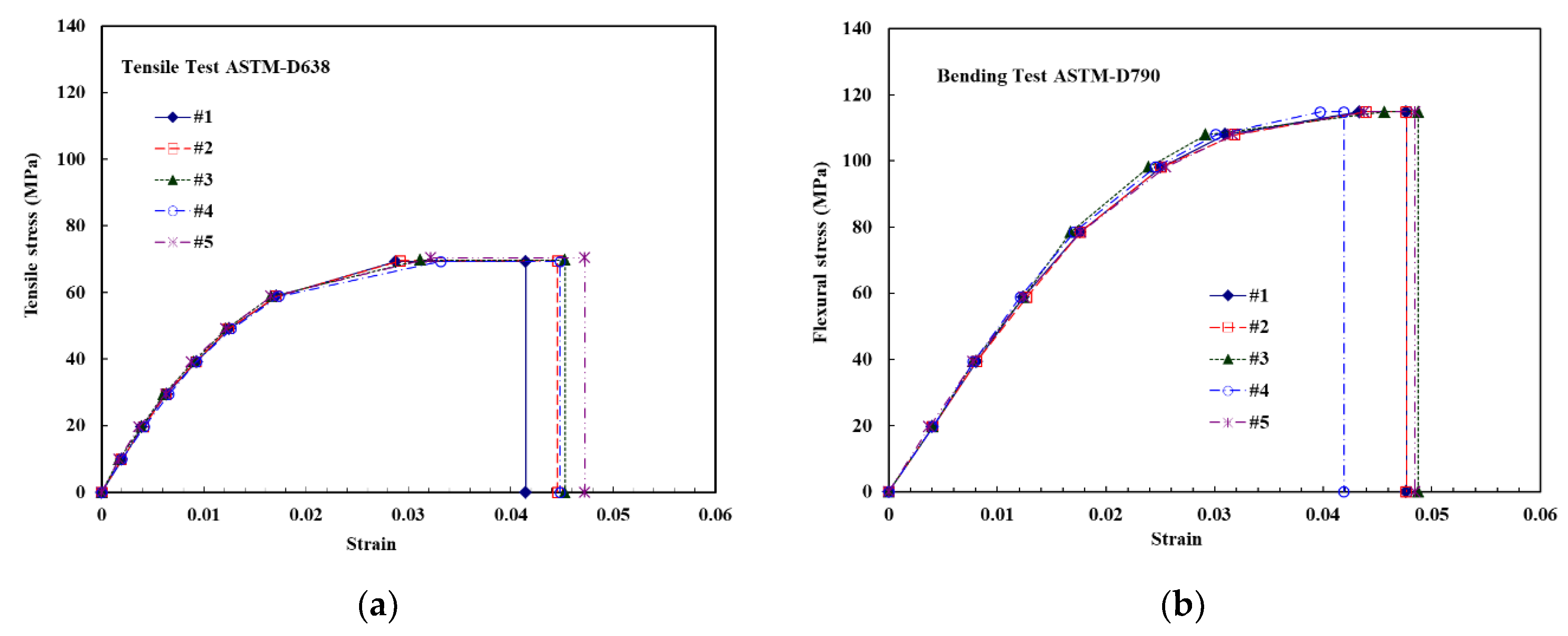
2.1. Material Strengths

As an initial application of the recycled plastic material, the proposed greenhouse frame is similar to the UP-type greenhouse issued by the COA of Taiwan. The UP-type greenhouse is constructed with galvanized cold-formed SSC400 steel, which is regulated by the CNS 6183 material standard of Taiwan [19]. The composite plastic material in this study is made of PET, Nylon, and glass fiber reinforced Nylon. Its flexural and tensile properties may be obtained following the ASTM D790 and D638 test method, respectively [20,21]. Figure 1a,b show the flexural and tensile stress-strain response of five test specimens manufactured and tested by the Plastic Industry Development Center of Taiwan. It is seen that consistently stable properties could be obtained for the composite plastic material. Table 1 compares the basic properties of the SSC400 steel and the composite plastic. It is seen that the elastic modulus and flexural yielding stress of the composite plastic were respectively approximated to 2.6% and 50% of the counterparts of the SSC400 steel. This implied that larger section dimensions should be provided for the composite plastic greenhouse for similar structural performance to the conventional galvanized steel greenhouse.

2.2. Design of Section

Sectional rigidity of a structural frame, which is expressed as the product of elastic modulus E and the sectional moment of inertia I, is highly relevant to its performance under external loadings. Therefore, an appropriate EI value was the first criterion for determining the sectional dimensions of the composite plastic greenhouse. Moreover, the feasibility in practical manufacture was considered in the determination. Accordingly, a pipe section (φ 50 × 10), a square-tube section (□ 50 × 50 × 10), and a square-tube section with crisscross inside (田 50 × 50 × 5) were selected as shown in Table 2. The φ 50 × 10 pipe section had an outer diameter of 50 mm and a wall thickness of 10 mm. The square-tube section had a 50-mm outer side length and a 10-mm wall thickness, which was represented as □ 50 × 50 × 10. The square-tube section with crisscross had a 50-mm outer side length and 5-mm wall and crisscross thicknesses, which was represented as 田 50 × 50 × 5. Their EI values and sectional tensile, compressive, and flexural strengths were compared with that of the typical sections (φ 26.2 × 1.6) used in the galvanized steel greenhouse. Since the galvanized steel section was used as the basis of comparison, the compressive and flexural strengths shown in the table were calculated according to the design formulae in the AISC Specification for Structural Steel Buildings [22] with an assumed effective length of 2 m. It is seen that the 田 50 × 50 × 5 section had a sectional rigidity EI and axial compressive strength approximated to that of the steel section. Hence, it was used in the composite plastic greenhouse frames to examine the response under design wind loads.

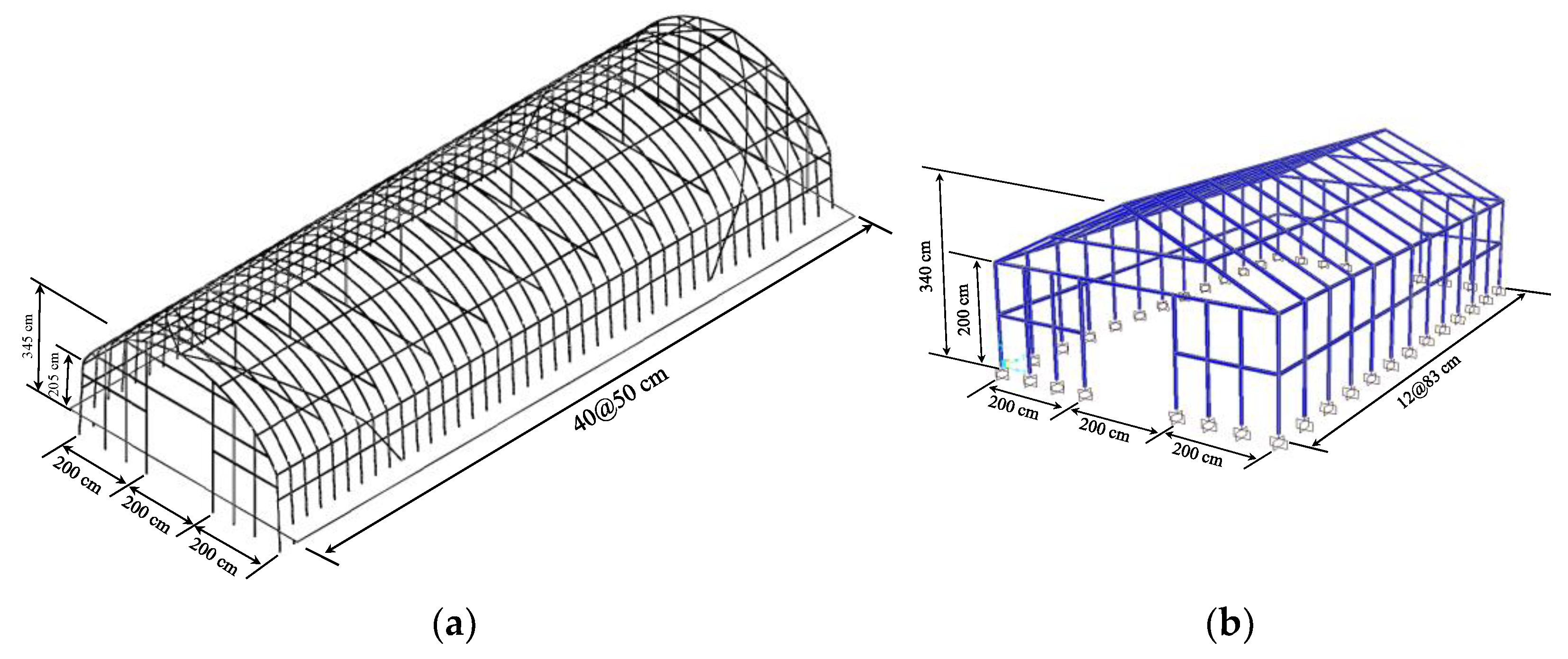
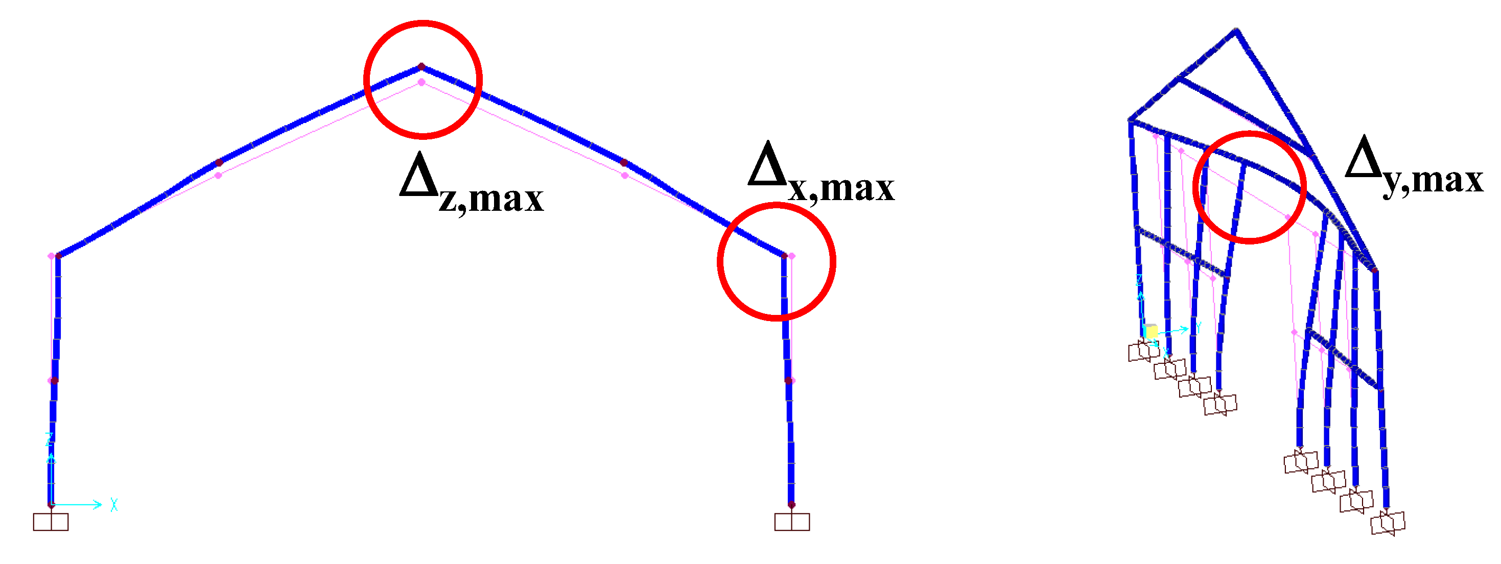
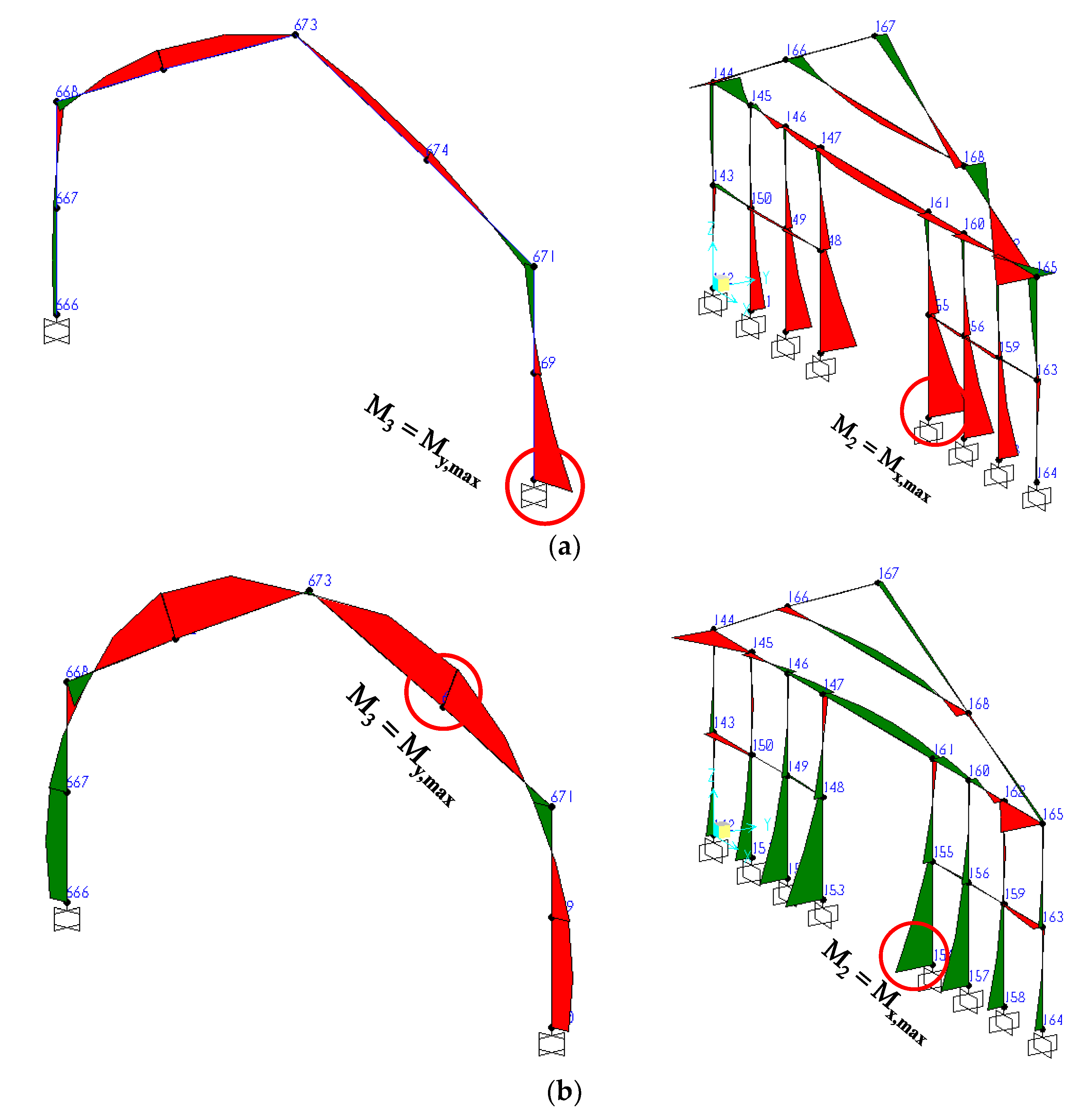
2.3. Structural Model

The wind-resisting frames of the UP-type greenhouse consisted of a series of curved portal frames with 500 mm center-to-center spacing, as shown in Figure 2a. Considering the practicability of the composite plastic product, the curved portal frames were changed into a series of gable frames for the proposed composite plastic greenhouse, as shown in Figure 2b. The greenhouse had a center-to-center plan dimension of 600 cm in width and 996 cm in length. The center-to-center spacing of the gable frames was 83 cm. The roof ridge was 3.4 m above the ground and the column posts were 2 m high. The gable frames at both ends of the greenhouse were composed of eight columns and two horizontal joists to form the main resisting systems against wind loads.
To evaluate the performance of the composite plastic greenhouse under design wind load, two beam-column finite element models as the structural form in Figure 2b, one with SSC400 φ 26.2 × 1.6 steel sections and the other with the composite plastic 田 50 × 50 × 5 sections, were constructed using the commercial SAP2000 program [11]. Structural members of the greenhouse frames were simulated with beam-column elements. Material properties shown in Table 1 were used for the structural members. The φ 26.2 × 1.6 steel sections were obtained from assigning the outer diameters and wall thickness to the default pipe section in the program. However, the 田 50 × 50 × 5 section was constructed using the Section Designer function in the program. Fixed-base conditions and rigid joint connections were assumed for the structural frames. Self-weight of structural members were automatically considered and used as the dynamic mass in the eigenvalue analysis. The first three modal periods of the two greenhouse models are shown in Table 3. Both models had their first mode vibration in the vertical direction, second mode vibration in the transverse direction, and third mode vibration in the longitudinal direction. The self-weight of each model is also included in the table. The model designed with the composite plastic sections had larger self-weight than that with the SSC400 steel sections. That was because of the apparently larger sectional area used in the plastic greenhouse. Therefore, its modal periods were moderately larger than the steel greenhouse. The quasi-static longitudinal and transverse responses of the two structural models under specified design wind load were compared in the next section.

3. Results and Discussion

3.1. Performance Evaluation

Most of the standard greenhouse structures issued by the COA of Taiwan were specified as resistant to the Beaufort Scale 11 wind load [23]. Hence, this wind scale was selected to determine the loading on the greenhouse models. The correspondent design wind speed is 33.0 m/s. As described in the structural analysis report issued by the Agriculture and Food Agency (AFA) of Taiwan, the greenhouse was regarded as an enclosed building frame and subject to Exposure Category C, which is open terrain with scattered obstructions having heights generally less than 9.1 m [24]. The design wind pressure was calculated as
p = q G C p q i ( G C p i ) ,
where q and qi are the external and internal velocity pressure, respectively. C p is the external pressure coefficient and G is the gust-effect factor. ( G C p i ) is the product of the internal pressure coefficient and the gust-effect factor. The external velocity pressure was calculated as
q ( z ) = 0.589 K ( z ) K z t [ I V 10 ( C ) ] 2   ( N / m 2 ) ,
where K(z) is the velocity pressure exposure coefficient evaluated at height z and K z t is the topographic factor. The former was calculated as 0.812 and the latter was 1.0 in this study. I is an importance factor, which was equal to 0.9 for the greenhouse. V 10 ( C ) is the basic wind speed for Exposure Category C and was equal to 33.0 m/s. The design wind pressure was calculated as 421.8 N/m2 and then multiplied with the tributary width of each structural member to obtain the equivalent uniformly distributed wind loads. Longitudinal (Y) and transverse (X) axes of the structural plan were considered as the main wind directions for the greenhouse. Linearly static analyses under the wind loads were conducted for the greenhouse models and their responses were compared to evaluate the adequacy of the composite plastic sections.
Table 4 compares the peak displacement responses of the two models in the longitudinal (Y), transverse (X), and vertical (Z) directions under the equivalent static wind loads. It is seen that the composite plastic greenhouse model had moderately larger displacement response to that of the galvanized steel greenhouse. Nevertheless, both models had comparable peak sectional forces, as presented in the next section. Therefore, it was determined not to increase the sectional dimensions of the composite plastic members. Figure 3 shows the nodal locations of the peak displacement response in the X, Y, and Z direction under the design wind loads. As shown in the figure, the peak displacement response in the X and Z direction respectively occurred at windward rafter-column joint and the roof ridge of the portal frame. The peak longitudinal displacement occurred at the joist-column joint of the gable frame.
Table 5 shows the peak sectional internals of the two models under the design wind loads. The subscript “2” and “3” refer to the local axes of the member sections. It is seen that both models had comparable maximum sectional forces. Although most of the structural members were subjected to axial tension, the joists of the gable frames on both sides of the greenhouse might suffer from compression. The maximum axial compression occurred in the horizontal joists of the gable frames. Under the transverse (X) wind load, the maximum moments occurred at the column base of the middle and the sideward gable frames, as shown in Figure 4a. The maximum M3 and M2 were respectively induced by the windward and sideward loadings. Figure 4b shows the locations of the maximum moments under the longitudinal (Y) wind load. The maximum moment on the windward frame occurred at the column base of the sideward frame. The uplift loading on the roof induced a maximum M3 at the mid-span of the roof rafter.
As compared with Table 2, it was realized that the maximum flexural demand of the steel greenhouse would exceed its yield strength under the design wind load. It could be even larger than the plastic flexural strength of the steel section, which was 0.238 kN-m. This implied that plastic deformation could be induced and the steel greenhouse could have displacement response apparently larger than that shown in Table 4 under the Beaufort Scale 11 wind load. On the contrary, the maximum flexural demand of the composite plastic greenhouse was below its yield strength. This confirmed a conservative design for the composite plastic members.
The maximum section forces obtained from the linearly elastic analysis under the equivalent static wind load were used to design the fasteners of the composite plastic members. Cold-form stainless steel was used for the fasteners. The design process was composed of drawing the 3D model of the fasteners and simulating the sectional forces under the design wind load. Thread bolts were used to fix the fasteners on the structural members. Details of the fastener design can be found in reference [25].

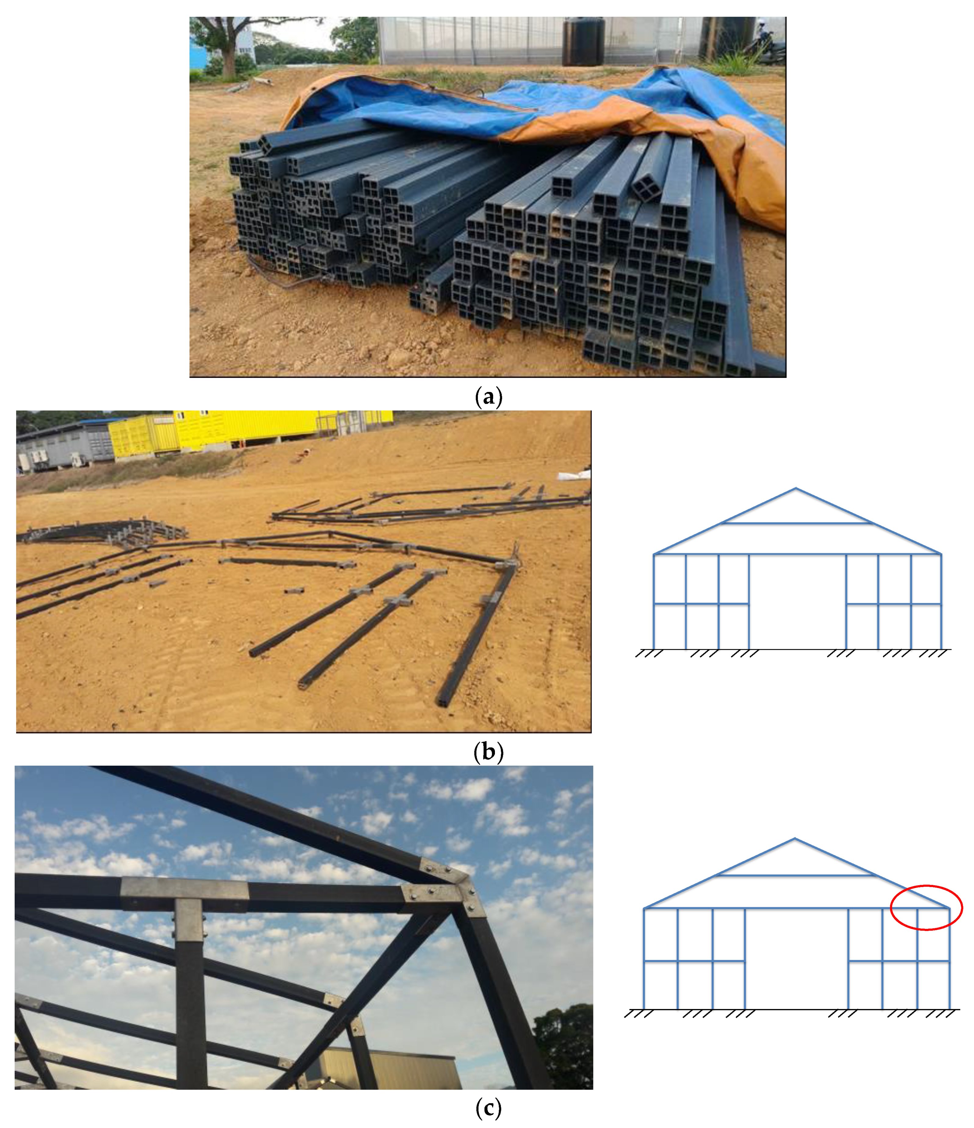
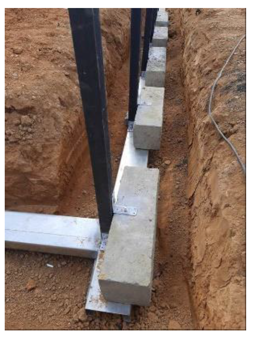
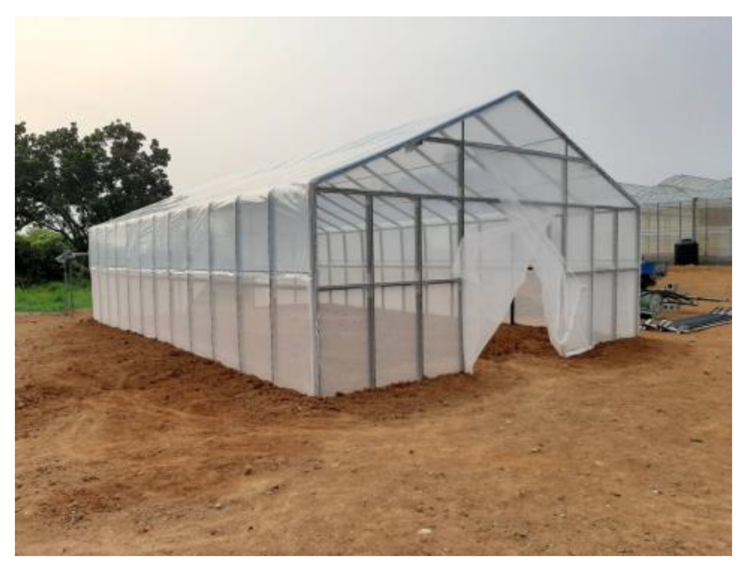
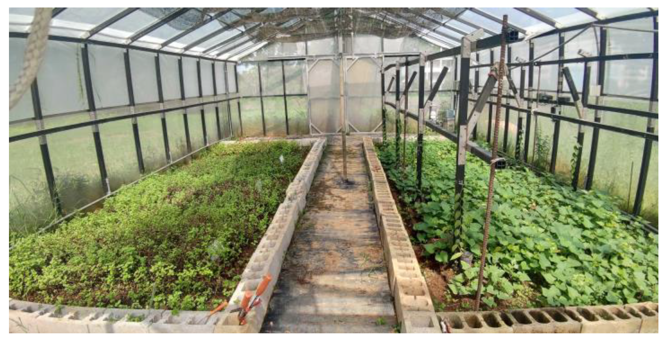
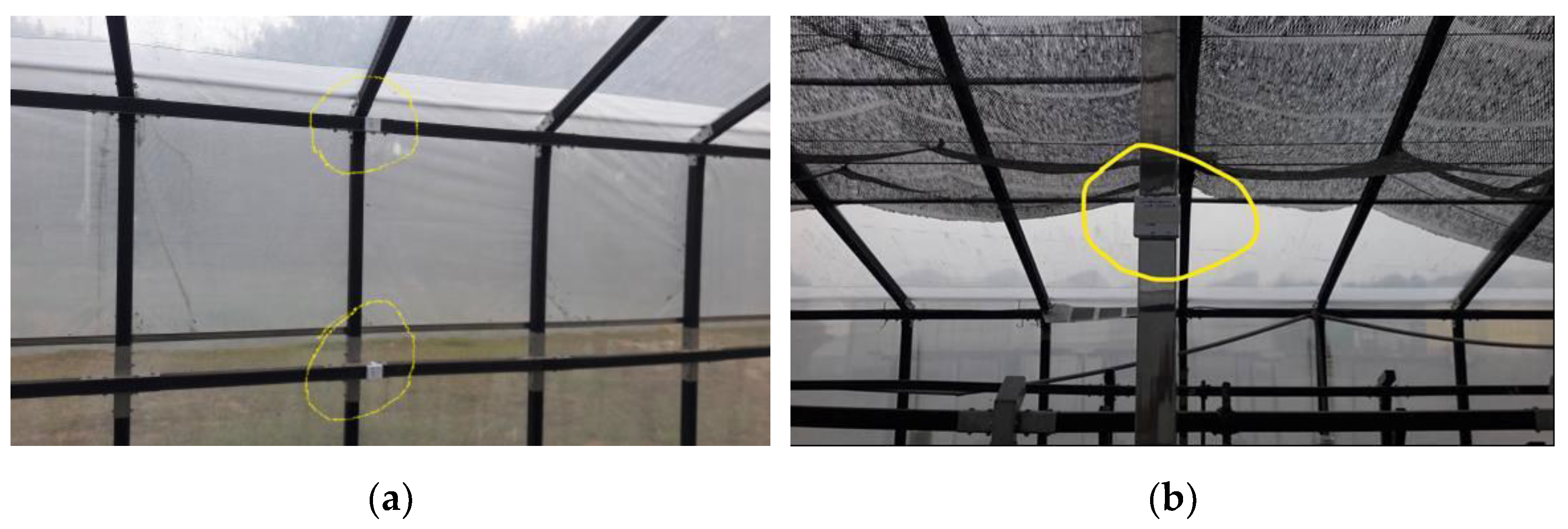
3.2. Field Construction

From the evaluation of the sectional properties and structural performance of the composite plastic greenhouse, the sectional dimensions were confirmed and the structural members were manufactured by the Plastic Industry Development Center of Taiwan. According to structural design drawings, three different member lengths of 2.5 m, 3.3 m, and 2.0 m were produced and processed on site for construction. Figure 5a shows the raw members delivered from the manufacturer. The raw members were trimmed to the designed lengths on site according to the design drawings. Figure 5b shows the assembling process of the gable frames. Structural members were assembled using stainless steel fasteners to form the planar gable frames. Planar gable frames were then connected through roof ridges and purlins to form a complete structural frame. Figure 5c shows the joint fastener of the column, rafter, and joist of the gable frame.
From the structural analysis results, it was realized that the greenhouse had to resist a 20,267 kN uplifting force under the design wind load. This indicated that the columns had to be appropriately tied to the ground. Therefore, a 500 mm deep and 500 mm wide trench was dug along the perimeter of the premises for construction of the structural foundation. The foundation was constructed with welded steel C-channels aligned with the perimeter of the premises. The welded C-channels helped to level off the gable frames and the column posts could be easily anchored to the steel channels, as shown in Figure 6. Moreover, concrete blocks were used to increase the gravity loading of the greenhouse to resist the uplifting wind loads. The total weight of the C-channels, concrete blocks, and cover soils on the C-channels was amounted to 50,698 kN, which was apparently larger than the uplifting force.
After the construction of the structural frame and anchorage of the columns, stainless steel glazing bars with card slots and circlips were used to fix the plastic covers on the frame members. Figure 7 shows the completed structural frame and plastic sheeting. After the completion, vanilla, sweet potato, spearmint, apple mint, peppermint, and lemon balm had been successfully grown in the composite plastic greenhouse, as shown in Figure 8.

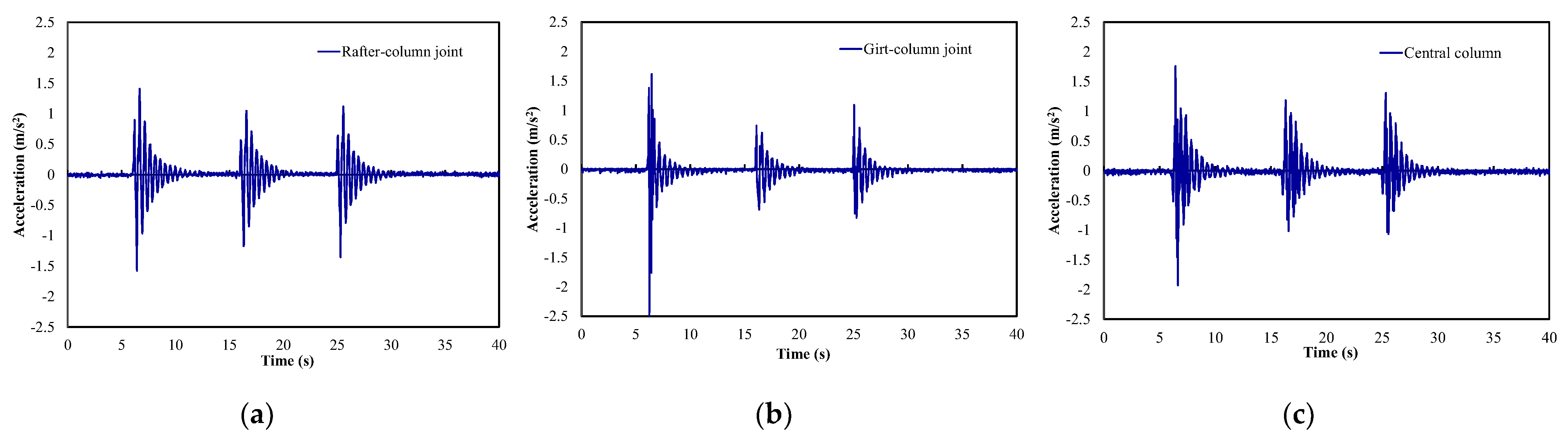
3.3. Field Free Vibration Tests

The structural design and performance evaluation of the composite plastic greenhouse under the equivalent static wind load were conducted using the numerical model. Rigid joint connections and fixed base were assumed for the designed fasteners and the structural foundation, respectively. Moreover, the composite plastic members were processed and assembled on site to construct the prototype greenhouse. Moreover, after the construction of the structural frame, a stainless steel column was supplemented to provide additional support to the middle gable frame for reducing the roof deflection under dead load. Therefore, field free vibration tests were conducted to investigate the adequacy of the assumptions and processing approaches made in the design and construction procedure.
Since the structure is more vulnerable to wind-induced vibration in the transverse direction, which is parallel to the planes of the gable frames, the test was conducted for the transverse vibration mode. Three PASCO wireless accelerometers [26] were instrumented to the middle gable frame and the central stainless column. The accelerometer had a measurement range of 16 g (1 g = 9.8 m/s2) with an accuracy of 0.002 g. One was attached to the rafter-column joint and another to the girt-column joint, as indicated in Figure 9a. The girt-column joint was located at half height of the rafter-column joint. The third one was attached to the central stainless steel column at the same height as the rafter-column joint, as shown in Figure 9b.
Free vibration was generated by pushing the middle gable frame from the outside of the greenhouse to a deformed state artificially and then suddenly released. The pushing-and-releasing sequence was repeated three times. Figure 10a–c show the recorded acceleration time histories at the rafter-column joint, girt-column joint, and central column of the gable frame, respectively. The acceleration data was recorded at 50 Hz sampling rate. It is seen from Figure 10a,c that except for the first spike of each test, the rafter-column joint and the central column had similar acceleration magnitude. This revealed that the gable frame had good integrity under the free vibrations. Moreover, the girt-column joint presented an acceleration response approximated to two-thirds of the rafter-column joint.
The fundamental period and damping ratio of the greenhouse structure in the transverse direction were estimated from the recorded time histories of each test. The first spike cycle was omitted in the estimation. Accordingly, the fundamental period, T, was calculated as
T = ( t i + N t i ) / N ,
where t i and t i + N were the time of the i-th and (i+N)-th peak in the time histories, respectively. N was the number of cycles. Moreover, the damping ratio, ξ , was calculated using the logarithmic decrement method [27] as
ξ = ln ( A i + N / A i ) / N 4 π 2 + [ ln ( A i + N / A i ) / N ] 2 ,
where A i and A i + N were the magnitude of the i-th and (i+N)-th peak in the acceleration time histories, respectively.
Table 6a presents the calculated periods from each accelerometer for the three tests. It is seen that consistent vibration periods were obtained from the free vibration tests. The average fundamental period was 0.476 s, which was slightly smaller than the transverse modal period 0.498 s in Table 3. The main reason was that the central column was not included in the original numerical model. When the central column was included in the numerical model, the transverse modal period would be 0.457 s. This indicated that the numerical structural model could capture the vibration characteristic of the prototype greenhouse. Table 6b presents the calculated damping ratios from each accelerometer for the three tests. It is seen that the damping ratio varied from 5.0% to 8.2%, depending on the location and vibration amplitude [28]. The average damping ratio was 6.2%, which was apparently larger than the conventional assumed 2% damping ratio for the galvanized steel greenhouse structures. Because of the larger damping ratio, the composite plastic greenhouse can have better vibration mitigation under wind excitations than the conventional galvanized steel greenhouse constructed under the same conditions.

3.4. Discussion

Wind load is the major environmental loading for the design of greenhouse structures. From the comparison study by Kim et al. [29], the calculations of wind load are similar among several greenhouse design standards. Therefore, the performance evaluation of the prototype composite plastic greenhouse was conducted under the conventional design wind load. Similar to the studies by Emekli et al. [9], Saltuk [10], and Indore et al. [7], most of the structural members were suffered from axial tensions. However, according to the tensile capacity of either the SSC400 galvanized steel or the composite plastic section, tensile failure was unlikely to occur. Instead, the proposed prototype greenhouse frame was more vulnerable to flexural failure under the design wind loads. The maximum moment could occur at the column base or the roof rafter, which was similar to the analysis results revealed by Kendirli [30].
The numerical structural model of the prototype greenhouse had a transverse fundamental period of 0.457 s, which was only 4% less than the average measured period of 0.476 s from the free vibration tests. This indicated that the assumption of rigid connection was valid for the composite plastic greenhouse. Therefore, the custom-made fasteners could provide sufficient constrain on the member connections. Moreover, the specially designed foundation could provide adequate fixity for the column bases. Sufficient base fixity and connection constrain made the deformation of the prototype greenhouse occurred in the composite plastic members rather than the joints. The nature of the composite plastic contributed to higher damping ratio than conventional steel greenhouses [31]. However, because the section of the composite plastic members was determined on the basis of the specified structural type and dimensions, further studies should be conducted prior to its application to different types of greenhouses.

4. Conclusions

A composite plastic material made of recycled PET, Nylon, and glass fiber reinforced Nylon was proposed for application to a simple greenhouse structure. The composite plastic material has a lower elastic modulus and yield strength as compared with conventional galvanized steel. Therefore, comparisons of member strengths and sectional rigidities were conducted to determine the appropriate section dimensions for the simple greenhouse structures. Performances of two greenhouse models constructed with the conventional SSC400 galvanized steel pipes and the composite plastic 田-sections under equivalent static wind loads were evaluated. The analysis results revealed that under the specified Beaufort Scale 11 wind load, both the galvanized steel and the composite plastic greenhouse models had comparable peak responses. However, with a significantly larger flexural strength for the designed 田-sections, the composite plastic greenhouse model was more resistant to the design wind load.
Production of the composite plastic members and custom-made fasteners were completed and a prototype greenhouse structure was constructed. On-site free vibration tests were conducted to validate the design assumptions and assembly procedure. The test results show that the prototype greenhouse had similar vibration period to that predicted from the numerical model. Moreover, the composite plastic greenhouse can have an average damping ratio of 6.2%, which is larger than the conventional assumed 2% damping for the galvanized steel greenhouse. Therefore, the composite plastic greenhouse can have better vibration mitigation under wind excitations. However, because the applied wind load may vary with the structural dimensions, such as structural height and width, the sectional and structural dimensions should be adhered to the current recommendations. Further studies should be conducted if the proposed composite plastic members would be applied to different structural types of greenhouses.

Author Contributions

Conceptualization, Y.-C.L. and M.-H.T.; methodology, M.-H.T.; software, M.-H.T.; validation, Y.-C.L. and M.-H.T.; formal analysis, M.-H.T.; investigation, Y.-C.L. and M.-H.T.; resources, Y.-C.L.; data curation, M.-H.T.; writing—original draft preparation, M.-H.T.; writing—review and editing, M.-H.T.; visualization, M.-H.T.; supervision, Y.-C.L.; project administration, Y.-C.L.; funding acquisition, Y.-C.L. All authors have read and agreed to the published version of the manuscript.

Funding

This research was funded by the Ministry of Science and Technology grant number MOST 107-2321-B-020-002.

Institutional Review Board Statement

Not applicable.

Informed Consent Statement

Not applicable.

Data Availability Statement

The data presented in this study are available on request from the corresponding author.

Conflicts of Interest

The authors declare no conflict of interest.

References

  1. INSPIRE Thematic Working Group. INSPIRE Data Specification on Agricultural and Aquaculture Facilities—Technical Guidelines; European Commission Joint Research Centre: Brussels, Belgium, 2013; Available online: https://inspire.ec.europa.eu/id/document/tg/af (accessed on 19 October 2021).
  2. Von Elsner, B.; Briassoulis, D.; Waaijenberg, D.; Mistriotis, A.; von Zabeltitz, C.; Gratraud, J.; Russo, G.; Suay-Cortes, R. Review of structural and functional characteristics of greenhouses in European Union countries: Part I, design requirements. J. Agric. Eng. Res. 2000, 75, 1–16. [Google Scholar] [CrossRef] [Green Version]
  3. Von Elsner, B.; Briassoulis, D.; Waaijenberg, D.; Mistriotis, A.; von Zabeltitz, C.; Gratraud, J.; Russo, G.; Suay-Cortes, R. Review of structural and functional characteristics of greenhouses in European Union countries: Part II, typical designs. J. Agric. Eng. Res. 2000, 75, 111–126. [Google Scholar] [CrossRef] [Green Version]
  4. Villagran, E.; Leon, R.; Rodriguez, A.; Jaramillo, J. 3D Numerical analysis of the natural ventilation behavior in a Colombian greenhouse established in warm climate conditions. Sustainability 2020, 12, 8101. [Google Scholar] [CrossRef]
  5. Flores-Velazquez, J.; Montero, J.I.; Baeza, E.J.; Lopez, J.C. Mechanical and natural ventilation systems in a greenhouse designed using computational fluid dynamics. Int. J. Agric. Biol. Eng. 2014, 7, 1–16. [Google Scholar]
  6. López-Cruz, I.L.; Fitz-Rodríguez, E.; Salazar-Moreno, R.; Rojano-Aguilar, A.; Kacira, M. Development and analysis of dynamical mathematical models of greenhouse climate: A review. Eur. J. Hortic. Sci. 2018, 83, 269–280. [Google Scholar] [CrossRef]
  7. Indore, N.S.; Kale, S.J.; Bashir, A.A.; Singh, R.K.; Singh, H. Structural analysis of common existing greenhouses designs in different agro climatic zones of India. Int. J. Agric. Eng. 2020, 13, 80–89. [Google Scholar] [CrossRef]
  8. Gupta, D.; Santosh, D.T.; Debnath, S. Modeling and simulation application for greenhouse microclimatic studies and structural analysis. In Protected Cultivation and Smart Agriculture; Maitra, S., Gaikwad, D.J., Shankar, T., Eds.; New Delhi Publishers: New Delhi, India, 2020; pp. 300–312. [Google Scholar] [CrossRef]
  9. Emekli, N.Y.; Kendirli, B.; Kurunc, A. Structural analysis and functional characteristics of greenhouses in the Mediterranean region of Turkey. Afr. J. Biotechnol. 2010, 9, 3131–3139. [Google Scholar]
  10. Saltuk, B. Structural analysis example of steel construction greenhouses. Eur. J. Sci. Technol. 2019, 16, 61–68. [Google Scholar] [CrossRef]
  11. SAP2000 Version 12.0. Linear and Nonlinear Static and Dynamic Analysis and Design of Three-dimensional Structures; Computers and Structures Inc.: Berkeley, CA, USA, 2012. [Google Scholar]
  12. Chang, Y.C.; Wu, M.Z. Development and importance of domestic gardening facilities. Tech. Serv. Rep. Spec. Issue Gard. Facil. Cultiv. Sub-Trop. Reg. 1994, 47, 3–5. [Google Scholar]
  13. NGMA. Structural Design Manual; The National Greenhouse Manufacture Association (NGMA): Harrisburg, PA, USA, 2013. [Google Scholar]
  14. CEN. Greenhouses: Design and Construction- Part 1: Commercial Production Greenhouses CEN-PREN 13031-1; European Committee for Standardization: Brussels, Belgium, 2017. [Google Scholar]
  15. JGHA. Guidelines for Gardening Facilities Safety Constructions; Japan Greenhouse Horticulture Association (JGHA): Tokyo, Japan, 2015. [Google Scholar]
  16. Lin, M.Z.; Hung, T.C. Introduction of the agricultural greenhouse design drawings and structural calculation. Agric. Policy Aff. Counc. Agric. 2008, 188, 24–28. (In Chinese) [Google Scholar]
  17. Pack, M.; Mehta, K. Design of affordable greenhouses for east Africa. In Proceedings of the 2012 IEEE Global Humanitarian Technology Conference, Seattle, WA, USA, 21–24 October 2012; pp. 104–110. [Google Scholar] [CrossRef]
  18. Saglam, C.; Guzel, M.; Cetin, N. A greenhouse construction with fiber-reinforced plastic chords and triangular pyramid models. Fresenius Environ. Bull. 2018, 27, 9447–9452. [Google Scholar]
  19. CNS. Standard 6138: Light Gauge Steels for General Structures; Chinese National Standards (CNS); Bureau of Standards, Metrology and Inspection: Taipei, Taiwan, 2016. [Google Scholar]
  20. ASTM. Standard D638: Standard Test Method for Tensile Properties of Plastics; ASTM International: West Conshohocken, PA, USA, 2014. [Google Scholar]
  21. ASTM. Standard D790: Standard Test Methods for Flexural Properties of Unreinforced and Reinforced Plastics and Electrical Insulating Materials; ASTM International: West Conshohocken, PA, USA, 2017. [Google Scholar]
  22. AISC. Specification for Structural Steel Buildings (ANSI/AISC 360–10); American Institute of Steel Construction (AISC): Chicago, IL, USA, 2010. [Google Scholar]
  23. Chang, C.Y.; Tien, Y.S.; Chen, L.H. Studies on the improvement of wind resistance capacity in the walk-in tunnel greenhouse in Taiwan. Rep. Taichung Dist. Agric. Res. Ext. Stn. 2012, 114, 45–55. (In Chinese) [Google Scholar]
  24. MOI. Code and Commentary of Wind-Resistant Design for Buildings; Ministry of Interior (MOI): Taipei, Taiwan, 2015. [Google Scholar]
  25. Yang, C.J.; Wang, C.H.; Lee, Y.C.; Tsai, M.H. Recycled plastic composite rod-based design of fasteners in the simplified greenhouse. Int. J. Mater. Mech. Manuf. 2019, 7, 210–213. [Google Scholar] [CrossRef]
  26. PASCO. Reference Guide 013-15734A; PASCO Scientific: Roseville, CA, USA, 2021. [Google Scholar]
  27. Chopra, A.K. Dynamics of Structures: Theory and Applications to Earthquake Engineering; Prentice-Hall: Hoboken, NJ, USA, 1995. [Google Scholar]
  28. Tsai, M.H.; Zhang, J.; Song, Y.P.; Lu, J.K. Dynamic performance of a composite building structure under seismic ground motions. Earthq. Struct. 2018, 15, 179–191. [Google Scholar] [CrossRef]
  29. Kim, R.; Lee, I.; Yeo, U.; Lee, S. Evaluation of various national greenhouse design standards for wind loading. Biosyst. Eng. 2019, 188, 136–154. [Google Scholar] [CrossRef]
  30. Kendirli, B. Structural analysis of greenhouses: A case study in Turkey. Build. Environ. 2006, 41, 864–871. [Google Scholar] [CrossRef]
  31. Ha, T.; Shin, S.H.; Kim, H. Damping and natural period evaluation of tall RC buildings using full-scale data in Korea. Appl. Sci. 2020, 10, 1568. [Google Scholar] [CrossRef] [Green Version]
Figure 1. (a) Bending test results; (b) tensile test results.
Agriculture 11 01051 g001
Figure 2. (a) UP-type standard greenhouse; (b) proposed composite plastic greenhouse.
Agriculture 11 01051 g002
Figure 3. Locations of peak displacement response under the design wind load.
Agriculture 11 01051 g003
Figure 4. (a). Locations of maximum moment under the transverse wind load. (b). Locations of maximum moment under the longitudinal wind load.
Agriculture 11 01051 g004
Figure 5. (a). Raw members delivered from the manufacturer. (b). Assembling process of the gable frames. (c). Joint fastener of the column, rafter, and joist.
Agriculture 11 01051 g005
Figure 6. Construction of the structural foundation.
Agriculture 11 01051 g006
Figure 7. The completed structural frame and glazing bars.
Agriculture 11 01051 g007
Figure 8. The growing plants in the prototype greenhouse (right garden bed: vanilla, sweet potato; left garden bed: spearmint, apple mint, peppermint, lemon balm).
Agriculture 11 01051 g008
Figure 9. (a) Location of accelerometers on the gable frame; (b) location of accelerometer on the central stainless column.
Agriculture 11 01051 g009
Figure 10. Recorded acceleration time histories at the (a) rafter-column joint; (b) girt-column joint; and (c) central column.
Agriculture 11 01051 g010
Table 1. Comparison of the basic properties.
MaterialE (GPa)σy (MPa)Density (kg/m3)
SSC400 steel2002457840
Composite plastic5.261151430
Note: E is the elastic modulus and σy is the flexural yield stress.
Table 2. Comparison of sectional properties and strengths.
MaterialSection (mm)EI (kN-m2)Pn (kN)Ty (kN)My (kN-m)
SSC400 steelφ 26.2 × 1.61.884.0630.30.176
Composite plasticφ 50 × 101.403.0487.51.226
Composite plastic□ 50 × 50 × 102.385.15103.02.081
Composite plastic田 50 × 50 × 51.764.5082.11.412
Note: EI is the sectional rigidity, Pn is the compressive strength, Ty is the tensile strength, and My is the flexural yield strength.
Table 3. Self-weight and the first three modal periods of the greenhouse models (s).
MaterialW (kN)T1T2T3
SSC400 steel2.4620.3570.3320.288
Composite plastic4.6210.5290.4980.427
Table 4. Comparison of peak displacement response (mm).
Wind DirectionSSC400 Galvanized SteelComposite Plastic
XYZXYZ
X550299698627389770
Y229273478243360509
Table 5. Comparison of peak internals under equivalent wind load (kN, m).
Wind DirectionSSC400 Galvanized SteelComposite Plastic
+P−PM3M2+P−PM3M2
X4.43−5.361.190.824.17−4.871.170.79
Y3.11−3.710.470.732.83−3.250.450.71
Table 6. (a) Estimated transverse fundamental periods (s). (b) Estimated transverse damping ratios.
(a)
Test No.Rafter JointGirt JointCentral Column
10.4680.4800.488
20.4760.4720.472
30.4760.4760.476
(b)
Test No.Rafter JointGirt JointCentral Column
16.4%5.1%8.2%
25.7%5.0%6.5%
36.7%5.2%7.3%
Publisher’s Note: MDPI stays neutral with regard to jurisdictional claims in published maps and institutional affiliations.

