Three-Dimensional Geometric Analysis of Balloon-Expandable Covered Stents Improves Classification of Complications after Fenestrated Endovascular Aneurysm Repair
Abstract
1. Introduction
2. Materials and Methods
2.1. Study Population
2.2. CTA Scan Protocol
2.3. Geometric Analysis of BECS
- Gap bridged by the BECS, defined as the centerline distance from the wall of the FSG to the orifice of the target artery at the aortic wall.
- Apposition between the BECS and the target artery, defined as the centerline distance from circumferential apposition between the BECS and the target artery to the distal end of circumferential apposition of the BECS.
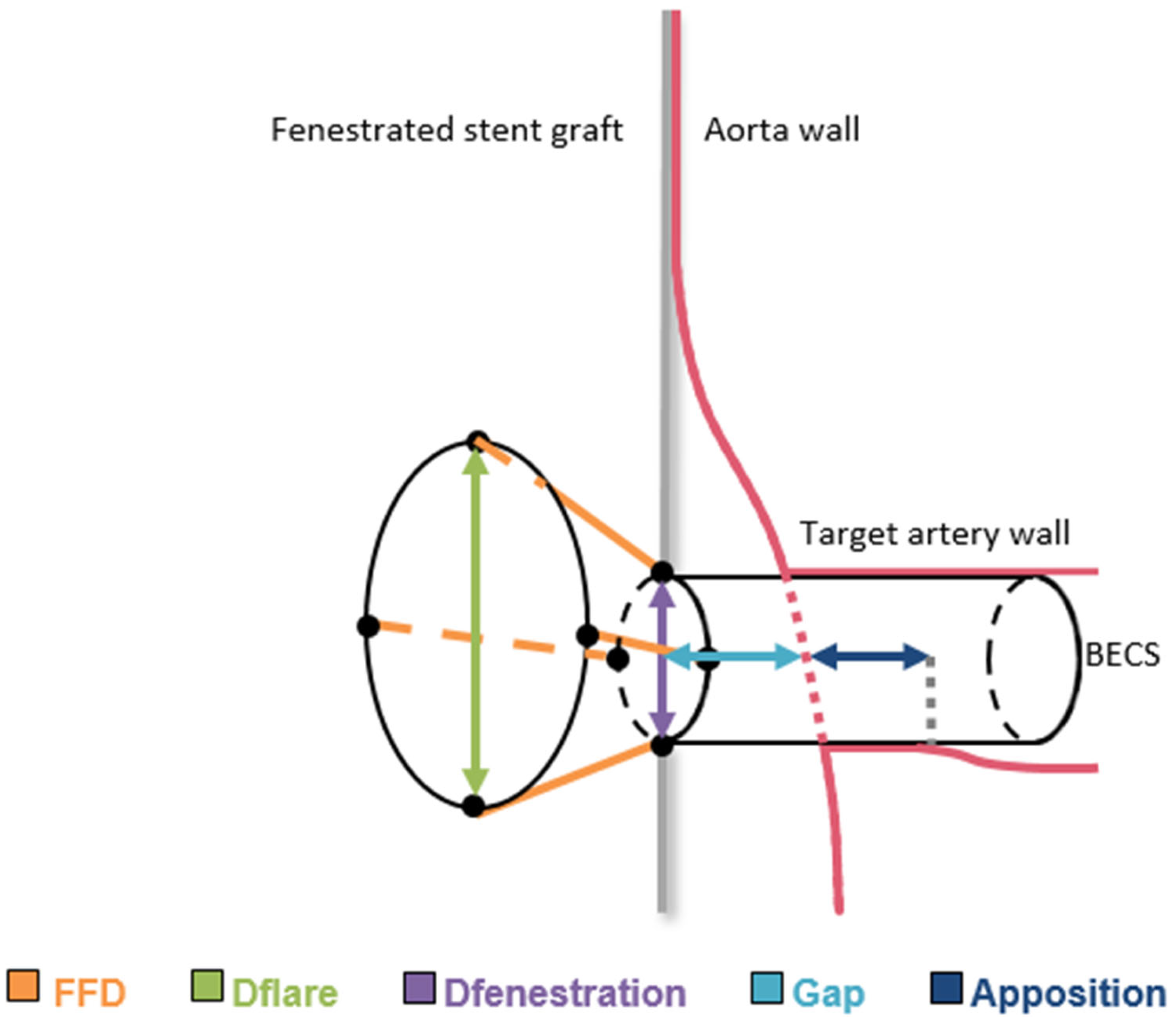
- Flare-to-fenestration distance (FFD), defined as the length of the BECS from the proximal end of the flare to its corresponding point at the fenestration. This is calculated for the entire circumference of the flare and reported as the shortest FFD.
- Diameter of the BECS at the proximal end of the flare (Dflare), reported as the minimum and maximum diameters.
- Diameter of the BECS at the fenestration (Dfenestration), reported as the minimum and maximum diameters.
2.4. BECS-Associated Endoleak Classification
- E1.
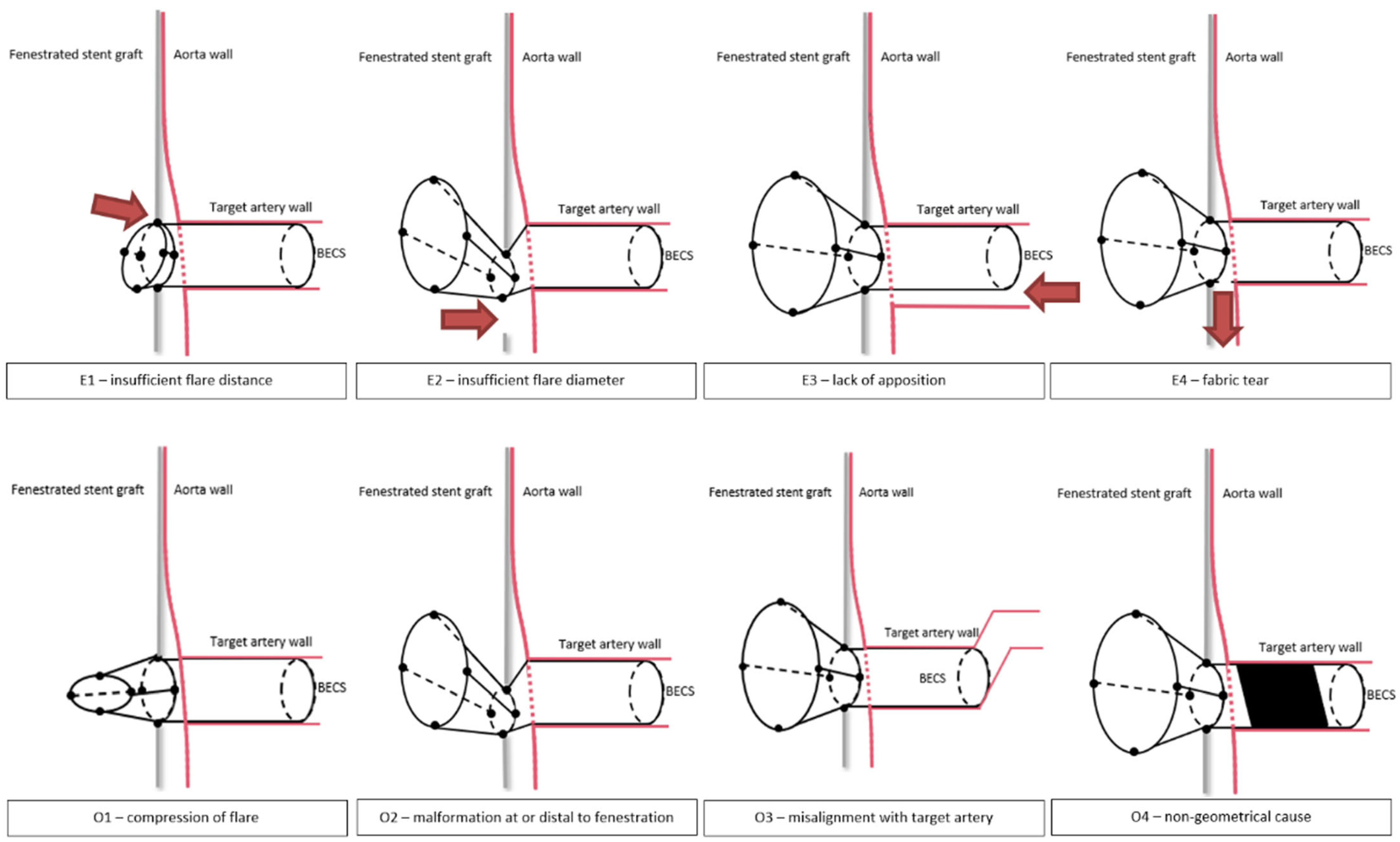
- The first cause of endoleak is insufficient proportion of the BECS inside the FSG, resulting in an endoleak between the flared end of the BECS and FSG fabric. During the FEVAR procedure, this can occur due to inadequate deployment of the BECS. During follow-up, this can occur when the BECS migrates out of the FSG. The required reintervention exists of proximal BECS extension.
- E2.
- The second cause of endoleak is a diameter mismatch between the flared end of the BECS and the fenestration, resulting in an endoleak. During the FEVAR procedure, this may occur during BECS deployment as a result of inadequate flaring or an undersized BECS compared to the dimensions of the fenestration, or dislocation of the BECS due to wire, catheter or delivery system maneuvers. During follow-up, this can occur as a result of BECS compression caused by FSG migration. The required reintervention exists of re-flaring the BECS and eventual proximal BECS extension.
- E3.
- The third cause of endoleak is insufficient apposition between the distal part of the BECS and the target artery, resulting in blood flow into the aneurysm. This type of endoleak has previously been classified by Oderich et al. as a type 1c endoleak [13]. During the FEVAR procedure, this can occur due to insufficient BECS length or an undersized BECS diameter compared to the diameter of the target artery. During follow-up, this can occur due to BECS migration towards the aortic lumen. One of the underlying mechanisms for this is an increasing gap between the FSG and the aortic wall due to progression of disease or secondary to another endoleak that promotes aneurysm growth. The required reintervention exists of distal BECS extension.
- E4.
- The fourth cause of endoleak is fabric tear. This type of endoleak has previously been classified by Oderich et al. as a type 3d endoleak [13]. During the FEVAR procedure, this can occur due to damage of the BECS fabric, for example by calcified arteries. During follow-up, this can be caused by a stent fracture resulting from BECS fatigue or FSG migration. The required reintervention exists of deployment of a new covered stent to seal the fabric tear or perforation.
2.5. BECS Obstruction Classification
- O1.
- The first cause of stenosis or occlusion is compression of the flared part of the BECS. During the FEVAR procedure, this can occur due to insufficient or failed flaring, or dislocation of the BECS due to wire, catheter or delivery system maneuvers. During follow-up, this can be due to collapse of the flare, potentially caused by FSG migration [16]. The required reintervention should focus on re-flaring of the BECS, eventually with proximal extension.
- O2.
- The second cause of stenosis or occlusion is BECS compression at the level of or distal to the fenestration, or blockage of the BECS inflow by the FSG fabric. During the FEVAR procedure, this can occur due to misalignment of the fenestration with the target artery. During follow-up, this can be caused by FSG migration, or the FSG fabric can obstruct the inflow of the target artery after complete FSG-BECS disconnection. The required reintervention exists of re-flaring the BECS and eventual proximal BECS extension with a new covered stent to strengthen the FSG-BECS connection.
- O3.
- The third cause of stenosis or occlusion is misalignment of the distal end of the BECS with the target artery. This may cause turbulent flow patterns or obstruction [17]. During the FEVAR procedure, this can be due to insufficient BECS length and/or hostile target artery anatomy such as curvature and tortuosity [18]. Especially for the celiac trunk, this mode of failure can also be caused by median arcuate ligament compression [19]. The reintervention should focus on relining of the distal end of the BECS.
- O4.
- The fourth cause of stenosis or occlusion is a non-geometric BECS related. Patient-related risk factors for BECS obstruction due to blood clotting and thrombus formation may be suspected when BECS geometry causes are ruled out. Low flow velocity results in low wall shear stress, which has been associated with thrombus formation [20]. In-stent thrombosis can occur at any time during follow-up.
2.6. BECS Fracture Classification
- F1.
- One single strut fracture;
- F2.
- Multiple single strut fractures;
- F3.
- Transverse linear BECS fracture without displacement;
- F4.
- Transverse linear BECS fracture with displacement.
2.7. Statistical Analysis
3. Results
3.1. Patient Outcomes
3.2. BECS Outcomes
3.3. BECS-Associated Endoleak
- E1.
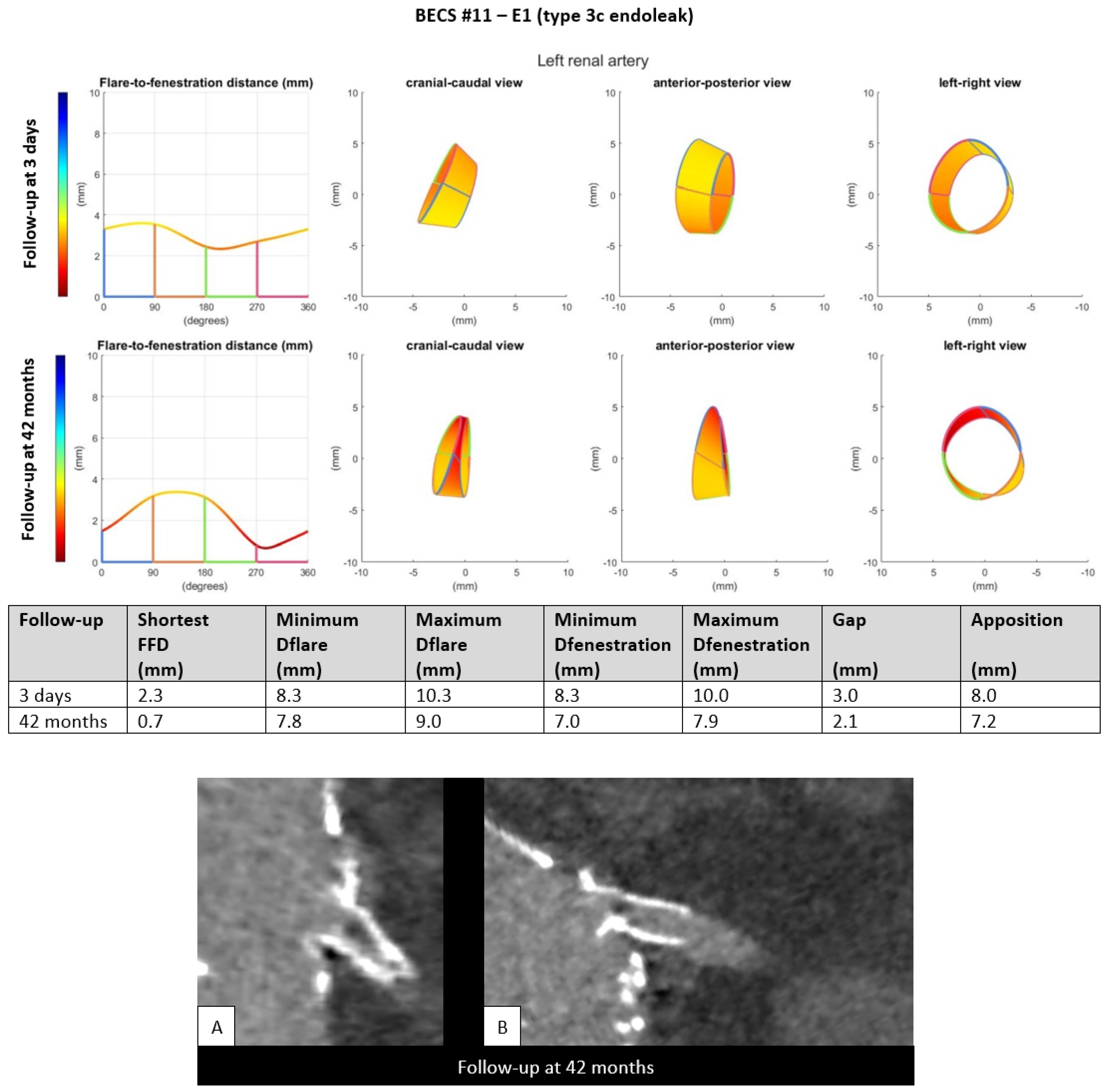
- Five BECSs had an endoleak due to insufficient length of the flare (FFD) or FSG-BECS disconnection and were categorized as E1 (Table 1, BECS #08, #09, #10, #11, and #12). BECS #11 is used as an example demonstrating this mode of failure (Figure 3). An endoleak of the BECS in the left renal artery was reported on the 42-months post-FEVAR CTA scan. Geometric analysis showed a shortest FFD of 2.3 mm on the 3-days post-FEVAR CTA scan and 0.7 mm on the 42-months post-FEVAR CTA scan, indicating BECS migration. The BECS was successfully relined with a proximal extension during reintervention.Figure 3. BECS #11 is an example of E1; endoleak due to insufficient flare distance. At the top, geometric analysis of 3-days and 42-months post-FEVAR CTA scans are shown. From left to right for both follow-up moments: circumferential FFD and cranial-caudal, anterior-posterior, and left-right view of the flare. At the bottom, (A) stretched vessel view of the aorta and (B) snake view of the left renal artery of the 42-months post-FEVAR CTA scan which showed the type 3c endoleak.Figure 3. BECS #11 is an example of E1; endoleak due to insufficient flare distance. At the top, geometric analysis of 3-days and 42-months post-FEVAR CTA scans are shown. From left to right for both follow-up moments: circumferential FFD and cranial-caudal, anterior-posterior, and left-right view of the flare. At the bottom, (A) stretched vessel view of the aorta and (B) snake view of the left renal artery of the 42-months post-FEVAR CTA scan which showed the type 3c endoleak.
- E2.
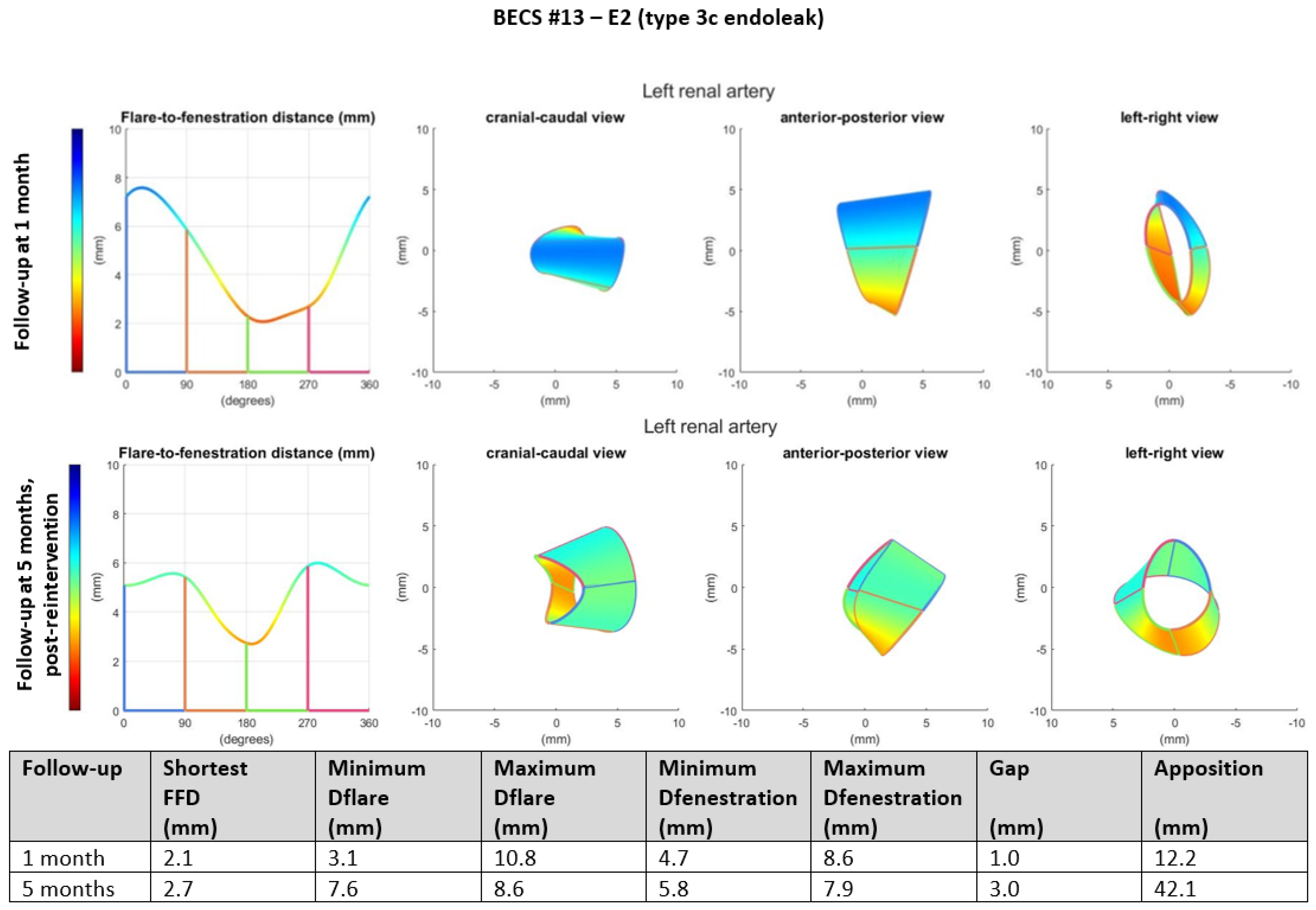
- Two BECSs had an endoleak due to insufficient flare resulting in mismatch between the diameter of the BECS and the fenestration and were categorized as E2 and E2/O1 (Table 1, BECS #13 and #14, respectively). BECS #13 is used as an example demonstrating this mode of failure (Figure 4). An endoleak of the BECS in the left renal artery was reported on the 1-month post-FEVAR CTA scan. Geometric analysis of this post-FEVAR CTA scan showed minimum and maximum diameters of the flare of 3.1 mm and 10.8 mm, indicating an oval-shaped flare. Fenestration dimensions of the FSG were 6 × 8 mm and minimum and maximum diameters of the BECS at the fenestration were 4.7 mm and 8.6 mm, causing the endoleak. This BECS was successfully relined by renewed flaring and placement of a proximal extension.Figure 4. BECS #13 is an example of E2, endoleak due to insufficient flare. Geometric analysis was performed for the 1-month post-FEVAR CTA scan and post-reintervention CTA scan. Insufficient flaring of the proximal end of the BECS caused a type 3c endoleak on the 1-month post-FEVAR CTA scan. The geometric analysis shows an oval-shaped flare with a minimum diameter of 3.1 mm. The endoleak was treated successfully by renewed flaring and proximal extension. The geometric analysis of the post-reintervention CTA scan shows a circle-shaped flare with a minimum diameter of 7.6 mm.Figure 4. BECS #13 is an example of E2, endoleak due to insufficient flare. Geometric analysis was performed for the 1-month post-FEVAR CTA scan and post-reintervention CTA scan. Insufficient flaring of the proximal end of the BECS caused a type 3c endoleak on the 1-month post-FEVAR CTA scan. The geometric analysis shows an oval-shaped flare with a minimum diameter of 3.1 mm. The endoleak was treated successfully by renewed flaring and proximal extension. The geometric analysis of the post-reintervention CTA scan shows a circle-shaped flare with a minimum diameter of 7.6 mm.
- E3.
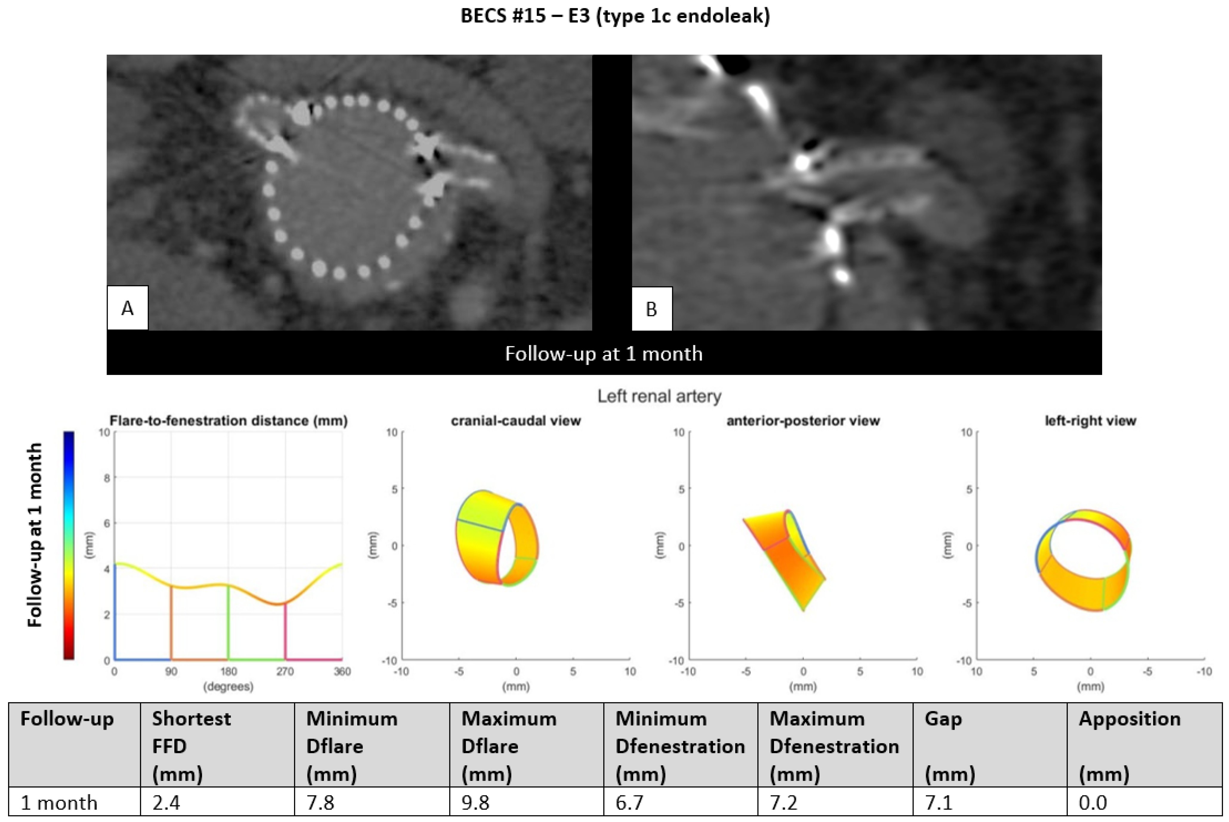
- One BECS had an endoleak due to loss of apposition between the BECS and the target artery and was categorized as E3 (Table 1, BECS #15). An endoleak of the BECS in the left renal artery was reported on the 1-month post-FEVAR CTA scan. Geometric analysis showed no circumferential apposition and a gap of 7.1 mm between FSG and aortic wall (Figure 5). This BECS was relined with an oversized balloon without resolving the endoleak. There was no further follow-up information available; the patient died from a stroke.Figure 5. BECS #15 is an example of E3, endoleak due to insufficient circumferential apposition between the BECS and the target artery. The 1-month post-FEVAR CTA scan ((A); axial view of the aorta, (B); snake view of the left renal artery) reported a type 1c endoleak. Geometric analysis was performed of the 1-month post-FEVAR CTA scan and reported lack of apposition.Figure 5. BECS #15 is an example of E3, endoleak due to insufficient circumferential apposition between the BECS and the target artery. The 1-month post-FEVAR CTA scan ((A); axial view of the aorta, (B); snake view of the left renal artery) reported a type 1c endoleak. Geometric analysis was performed of the 1-month post-FEVAR CTA scan and reported lack of apposition.
- E4.
- One BECS had an endoleak that is most likely caused by fabric tear and was categorized as E4 (Table 1, BECS #16). An endoleak of the BECS in the left renal artery was reported on the 1-month post-FEVAR CTA scan (Figure 6). Geometric analysis showed a sufficiently positioned BECS with a D-ratio of 0.9 for both the flare and the fenestration, and 10.3 mm apposition. There was no reintervention performed because this patient suffered oncological disease with poor prognosis.Figure 6. BECS #16 is an example of E4, endoleak due to fabric tear. The 1-month post-FEVAR CTA scan ((A); stretched vessel view of the aorta, (B); axial view of aorta) showed a flared BECS in the fenestrated stent graft, and the BECS is open. Geometric analysis of the 1-month post-FEVAR CTA scan showed no other cause that may explain the endoleak.Figure 6. BECS #16 is an example of E4, endoleak due to fabric tear. The 1-month post-FEVAR CTA scan ((A); stretched vessel view of the aorta, (B); axial view of aorta) showed a flared BECS in the fenestrated stent graft, and the BECS is open. Geometric analysis of the 1-month post-FEVAR CTA scan showed no other cause that may explain the endoleak.
3.4. BECS Obstruction
- O1.
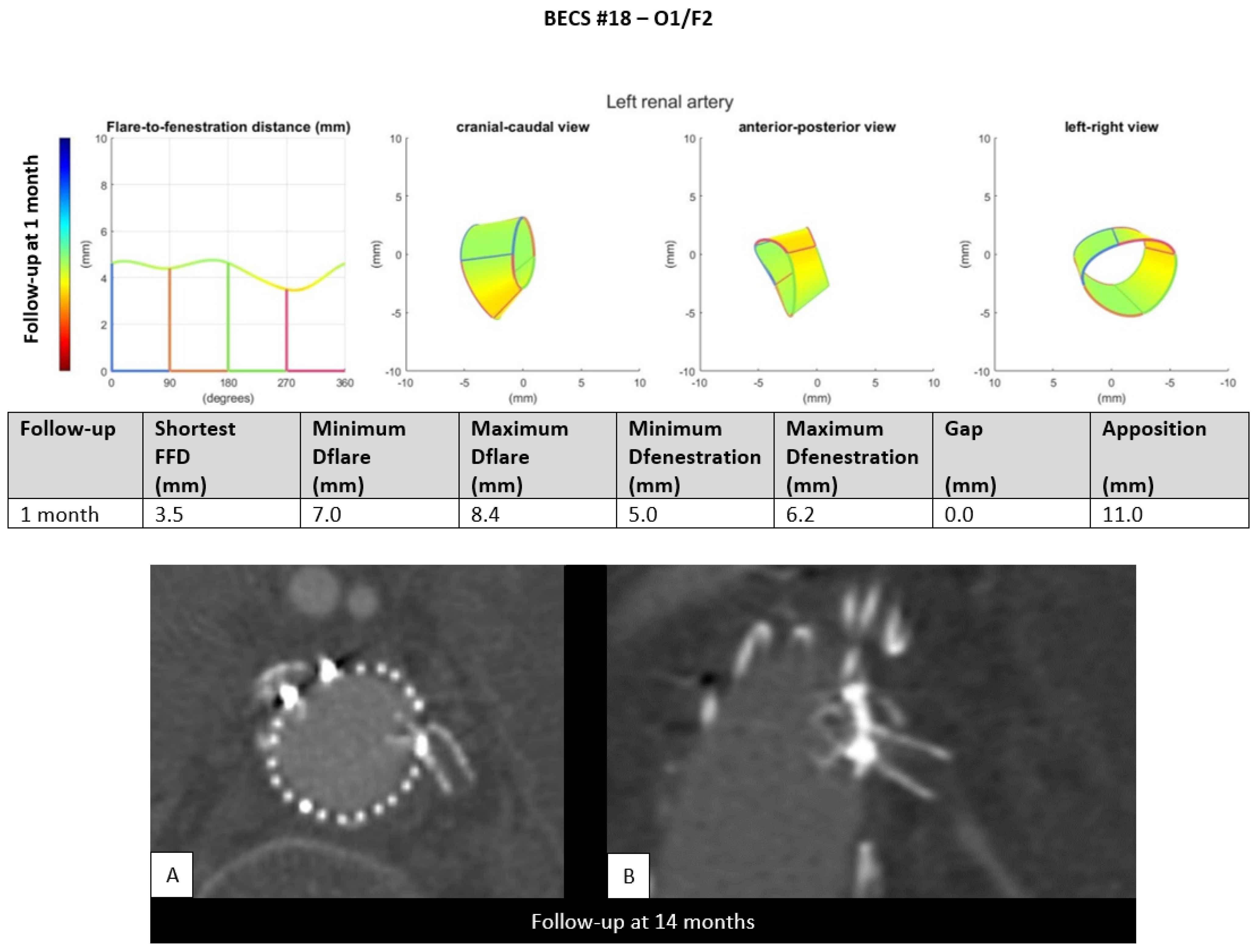
- Two BECSs had compression of the flared end and were categorized as O1 and O1/F2 (Table 1, BECS #17 and #18, respectively). BECS #18 is used as an example demonstrating this mode of failure (Figure 7). This BECS in the left renal artery was occluded and fractured on the 14-month post-FEVAR CTA scan. A collapsed flare was seen on the snake view of the target artery, caused by FSG migration. There were no treatment options for this patient.Figure 7. BECS #18 is an example of O1, combined with F2, obstruction due to flare compression and fracture of multiple struts. Geometric analysis of the 1-month post-FEVAR CTA scan shows a good flare with adequate diameters. The 14-months post-FEVAR CTA scan ((A); axial view of the aorta, (B); stretched vessel view of the aorta) showed a compressed and fractured BECS in the left renal artery.Figure 7. BECS #18 is an example of O1, combined with F2, obstruction due to flare compression and fracture of multiple struts. Geometric analysis of the 1-month post-FEVAR CTA scan shows a good flare with adequate diameters. The 14-months post-FEVAR CTA scan ((A); axial view of the aorta, (B); stretched vessel view of the aorta) showed a compressed and fractured BECS in the left renal artery.
- O2.
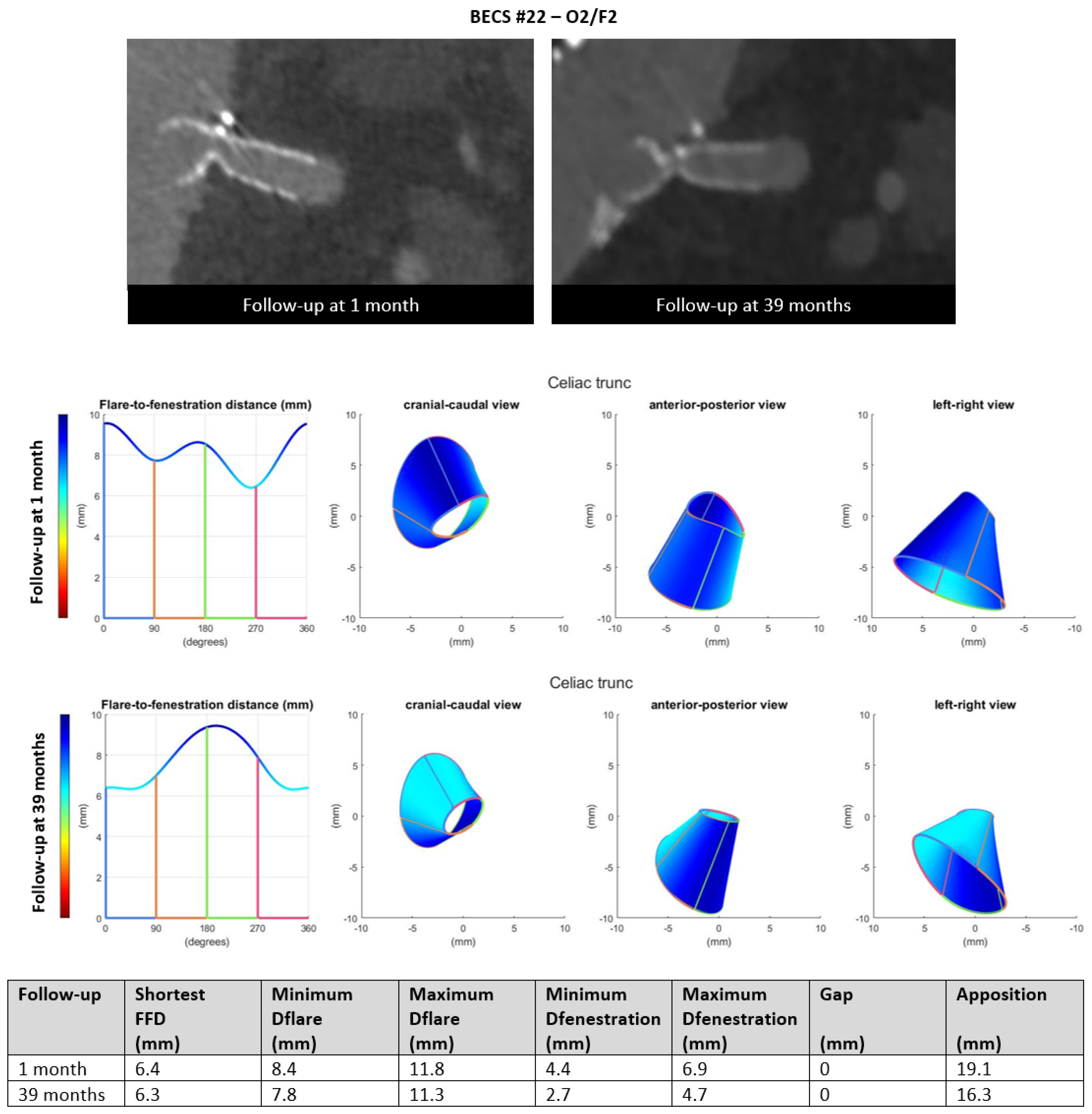
- Six BECSs had compression of the BECS at the level of the fenestration and were categorized; two as O2, three as O2/F2, and one as O2/F2/E1 (Table 1, BECS #19, #20, #21, #22, #23, and #24, respectively). BECS #22 is used as an example demonstrating this mode of failure (Figure 8). A 90% stenosis and type F2 fracture were reported for the BECS in the celiac trunk on the 39-months post-FEVAR CTA scan. Geometric analysis showed minimum and maximum diameter of fenestration of 4.4 by 6.9 on the 1-month post-FEVAR CTA scan, which decreased to 2.7 by 4.7 mm on the 39-months post-FEVAR CTA scan. BECS compression at the level of the fenestration was caused by FSG migration. A successful reintervention with Endoanchors was performed to prevent further FSG migration. There was no reintervention of the BECS complication performed due to technical difficulties.Figure 8. BECS #22 is an example of O2, combined with F2, obstruction due to compression at the fenestration and fracture of multiple struts. At the top, the snake view of 1-month and 39-months post FEVAR-CTA scans—at the bottom, geometric analysis of both follow-up moments, confirming the decreasing diameter at the height of the fenestration.Figure 8. BECS #22 is an example of O2, combined with F2, obstruction due to compression at the fenestration and fracture of multiple struts. At the top, the snake view of 1-month and 39-months post FEVAR-CTA scans—at the bottom, geometric analysis of both follow-up moments, confirming the decreasing diameter at the height of the fenestration.
- O3.
- One BECS was categorized as O3 (Table 1, BECS #25). This BECS in the celiac trunk had an 80% stenosis distal of the BECS on the 3-months post-FEVAR CTA scan (Figure 9). This was caused by median arcuate ligament compression. Geometric analysis showed subtle changes in BECS geometry between the 10-days and 3-months post-FEVAR CTA scan. There was no reintervention indicated by the physicians as the patient was symptom free and the SMA was patent with adequate collaterals to the distal celiac trunk branches.Figure 9. BECS #25 is an example of O3, obstruction due to misalignment or constriction of the distal end of the BECS with the target artery. At the top, geometric analysis of the 10-days and 3-months post-FEVAR CTA scans showed a good flare without major geometrical changes. At the bottom, the snake view of the 3-month post-FEVAR CTA scan showed 80% stenosis distal to the BECS due to median arcuate ligament compression.Figure 9. BECS #25 is an example of O3, obstruction due to misalignment or constriction of the distal end of the BECS with the target artery. At the top, geometric analysis of the 10-days and 3-months post-FEVAR CTA scans showed a good flare without major geometrical changes. At the bottom, the snake view of the 3-month post-FEVAR CTA scan showed 80% stenosis distal to the BECS due to median arcuate ligament compression.
- O4.
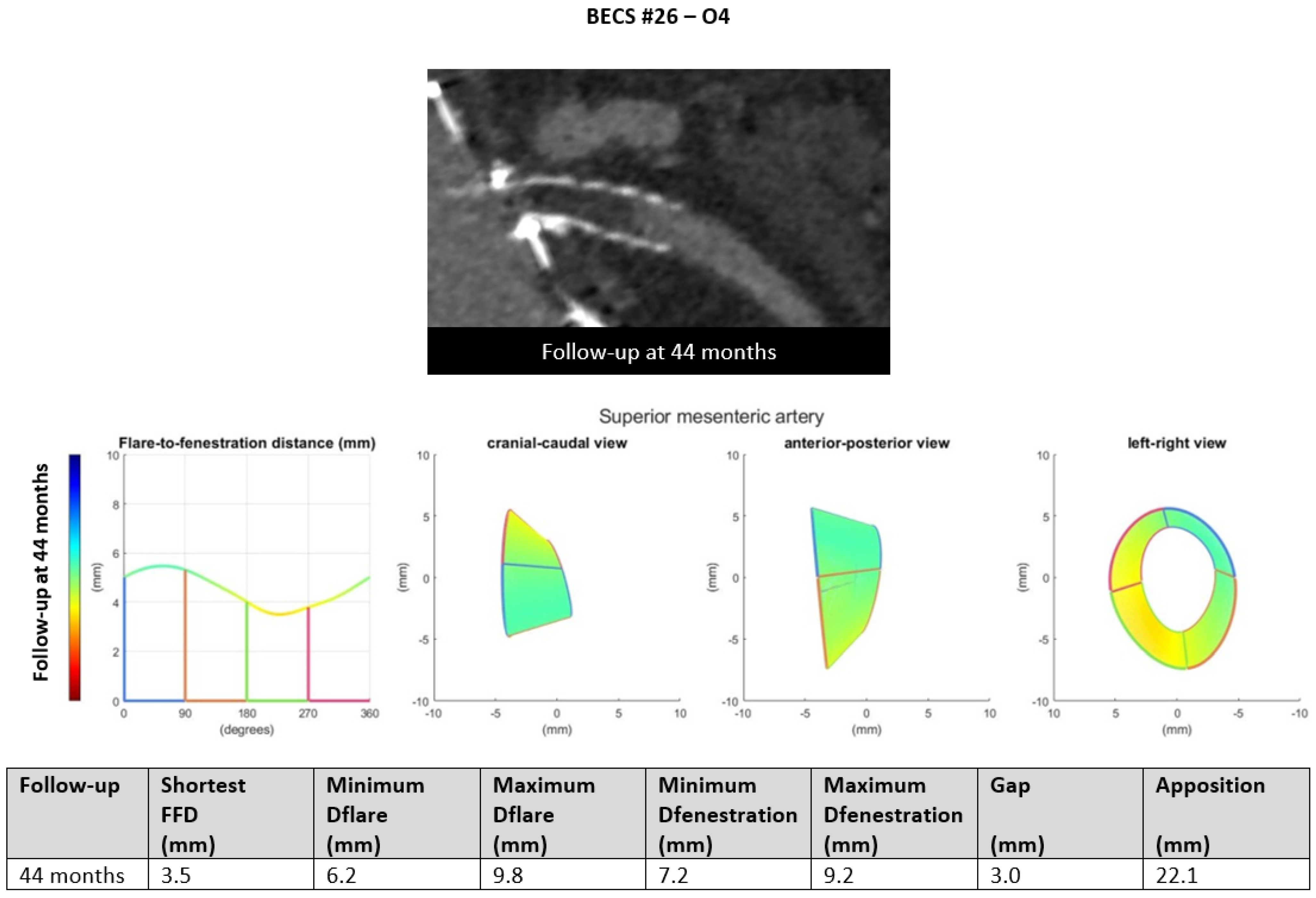
- Six BECSs had no geometric cause and were categorized as O4 (Table 1, BECS #26, #27, #28, #29, #30, and #31). BECS #26 is used as an example demonstrating this mode of failure (Figure 10). This BECS in the SMA was occluded on the 44-month post-FEVAR CTA scan. Geometric analysis showed no abnormalities of the BECS stent frame itself. The occlusion was caused by thrombosis due to confirmed cryoglobulinemia type 2. No reintervention was performed as the patient refused treatment and subsequently died as a result of multi-organ failure.Figure 10. BECS #26 is an example of O4, obstruction without a geometrical cause. The 44-month post-FEVAR CTA scan reported an occluded BECS. Geometric analysis showed no abnormalities of the BECS geometry that may have caused the occlusion.Figure 10. BECS #26 is an example of O4, obstruction without a geometrical cause. The 44-month post-FEVAR CTA scan reported an occluded BECS. Geometric analysis showed no abnormalities of the BECS geometry that may have caused the occlusion.
3.5. BECS Fracture
4. Discussion
5. Conclusions
Author Contributions
Funding
Institutional Review Board Statement
Informed Consent Statement
Data Availability Statement
Conflicts of Interest
Appendix A
References
- Antoniou, G.A.; Juszczak, M.T.; Antoniou, S.A.; Katsargyris, A.; Haulon, S. Editor’s Choice—Fenestrated or Branched Endovascular versus Open Repair for Complex Aortic Aneurysms: Meta-Analysis of Time to Event Propensity Score Matched Data. Eur. J. Vasc. EndoVasc. Surg. 2021, 61, 228–237. [Google Scholar] [CrossRef]
- Verhoeven, E.L.; Katsargyris, A.; Oikonomou, K.; Kouvelos, G.; Renner, H.; Ritter, W. Fenestrated Endovascular Aortic Aneurysm Repair as a First Line Treatment Option to Treat Short Necked, Juxtarenal, and Suprarenal Aneurysms. Eur. J. Vasc. EndoVasc. Surg. 2016, 51, 775–781. [Google Scholar] [CrossRef]
- Dossabhoy, S.S.; Simons, J.P.; Diamond, K.R.; Flahive, J.M.; Aiello, F.A.; Arous, E.J.; Messina, L.M.; Schanzer, A. Reinterventions after fenestrated or branched endovascular aortic aneurysm repair. J. Vasc. Surg. 2018, 68, 669–681. [Google Scholar] [CrossRef]
- Bootun, R.; Carey, F.; Al-Thaher, A.; Al-Alwani, Z.; Crawford, M.; Delbridge, M.; Ali, T.; Al-Jundi, W. Comparison between open repair with suprarenal clamping and fenestrated endovascular repair for unruptured juxtarenal abdominal aortic aneurysms. J. CardioVasc. Surg. 2022, 63, 44–51. [Google Scholar] [CrossRef]
- Sveinsson, M.; Sonesson, B.; Kristmundsson, T.; Dias, N.; Resch, T. Long-term outcomes after fenestrated endovascular aortic repair for juxtarenal aortic aneurysms. J. Vasc. Surg. 2022, 75, 1164–1170. [Google Scholar] [CrossRef]
- Patel, S.R.; Roy, I.N.; McWilliams, R.G.; Brennan, J.A.; Vallabhaneni, S.R.; Neequaye, S.K.; Smout, J.D.; Fisher, R.K. Characterising the incidence and mode of visceral stent failure after fenestrated endovascular aneurysm repair (FEVAR). JRSM CardioVasc. Dis. 2021, 10, 20480040211012503. [Google Scholar] [CrossRef]
- Mezzetto, L.; Scorsone, L.; Silingardi, R.; Gennai, S.; Piffaretti, G.; Mantovani, A.; Bush, R.L.; Haulon, S.; Veraldi, G.F. Bridging Stents in Fenestrated and Branched Endovascular Aneurysm Repair: A Systematic REVIEW. Ann. Vasc. Surg. 2021, 73, 454–462. [Google Scholar] [CrossRef]
- Resch, T.; de Vries, J.P.; Haulon, S. Optimising Target Vessel Patency after Complex Aortic Repair: Things We Know that We Know. Eur. J. Vasc. EndoVasc. Surg. 2021, 62, 4–6. [Google Scholar] [CrossRef]
- Overeem, S.; Schuurmann, R.; Schumacher, M.; Jolink, F.; Ketel, M.; Nijendijk, B.; Slump, K.; Versluis, M.; de Vries, J.P. Validation of a Novel Methodology to Evaluate Changes in the Flare Geometry of Renovisceral Bridging Stent-Grafts After Fenestrated Endovascular Aneurysm Repair. J. EndoVasc. Ther. 2020, 27, 436–444. [Google Scholar] [CrossRef]
- Van der Riet, C.; Schuurmann, R.C.L.; Bokkers, R.P.H.; van der Zijden, F.A.; Tielliu, I.F.J.; Slump, C.H.; de Vries, J.P.M. In Vitro Geometry Analysis of Fenestrations in Endovascular Aneurysm Repair. J EndoVasc. Ther. 2022. online ahead of print. [Google Scholar] [CrossRef]
- Van der Riet, C.; Schuurmann, R.C.L.; Verhoeven, E.L.G.; Zeebregts, C.J.; Tielliu, I.F.J.; Bokkers, R.P.H.; Katsargyris, A.; de Vries, J.P.M. Outcomes of Advanta V12 Covered Stents After Fenestrated Endovascular Aneurysm Repair. J. EndoVasc. Ther. 2021, 28, 700–706. [Google Scholar] [CrossRef]
- Schwartz, J. Calculating Percent Stenosis. Am. J. Neuroradiol. 2001, 22, 228. [Google Scholar]
- Oderich, G.S. Endovascular Aortic Repair: Current Techniques with Fenestrated, Branched and Parallel Stent-Grafts; Springer International Publishing: Cham, Switzerland, 2011. [Google Scholar]
- Squizzato, F.; Antonello, M.; Forcella, E.; Coppadoro, S.; Colacchio, C.; Xodo, A.; Grego, F.; Piazza, M. Geometrical determinants of target vessel instability in fenestrated endovascular aortic repair. J. Vasc. Surg. 2022, 76, 335–343.e2. [Google Scholar] [CrossRef]
- Crawford, S.A.; Osman, E.; Doyle, M.G.; Lindsay, T.F.; Amon, C.H.; Forbes, T.L. Impact of fenestrated stent graft misalignment on patient outcomes. J. Vasc. Surg. 2019, 70, 1056–1064. [Google Scholar] [CrossRef]
- De Niet, A.; Post, R.B.; Reijnen, M.; Zeebregts, C.J.; Tielliu, I.F.J. Geometric changes over time in bridging stents after branched and fenestrated endovascular repair for thoracoabdominal aneurysm. J. Vasc. Surg. 2019, 70, 702–709. [Google Scholar] [CrossRef]
- Ou, J.; Tang, A.Y.S.; Chiu, T.L.; Chow, K.W.; Chan, Y.C.; Cheng, S.W.K. Haemodynamic Variations of Flow to Renal Arteries in Custom-Made and Pivot Branch Fenestrated Endografting. Eur. J. Vasc. EndoVasc. Surg. 2017, 53, 133–139. [Google Scholar] [CrossRef]
- Fidalgo-Domingos, L.; San Norberto, E.M.; Fidalgo-Domingos, D.; Martín-Pedrosa, M.; Cenizo, N.; Estévez, I.; Revilla, Á.; Vaquero, C. Geometric and hemodynamic analysis of fenestrated and multibranched aortic endografts. J. Vasc. Surg. 2020, 72, 1567–1575. [Google Scholar] [CrossRef]
- Squizzato, F.; Oderich, G.S.; Tenorio, E.R.; Mendes, B.C.; DeMartino, R.R. Effect of celiac axis compression on target vessel-related outcomes during fenestrated-branched endovascular aortic repair. J. Vasc. Surg. 2021, 73, 1167–1177.e1161. [Google Scholar] [CrossRef]
- Tran, K.; Feliciano, K.B.; Yang, W.; Schwarz, E.L.; Marsden, A.L.; Dalman, R.L.; Lee, J.T. Patient-specific changes in aortic hemodynamics is associated with thrombotic risk after fenestrated endovascular aneurysm repair with large diameter endografts. JVS Vasc. Sci. 2022, 3, 219–231. [Google Scholar] [CrossRef]
- Lee, D.; Kim, J.K.; Jung, H.D.; Huh, T.W.; Yim, N.Y.; Oh, H.J.; Chang, N.K.; Choi, S.-J.-N. Risk Factors and Clinical Evaluation of Superficial Femoral Artery Stent Fracture: Protégé GPS Stent. J. Korean Soc. Radiol. 2010, 63, 513–518. [Google Scholar] [CrossRef][Green Version]
- Tenorio, E.R.; Oderich, G.S.; Sandri, G.A.; Ozbek, P.; Kärkkäinen, J.M.; Macedo, T.A.; Vrtiska, T.; Cha, S. Impact of onlay fusion and cone beam computed tomography on radiation exposure and technical assessment of fenestrated-branched endovascular aortic repair. J. Vasc. Surg. 2019, 69, 1045–1058.e1043. [Google Scholar] [CrossRef]
- Dijkstra, M.L.; Eagleton, M.J.; Greenberg, R.K.; Mastracci, T.; Hernandez, A. Intraoperative C-arm cone-beam computed tomography in fenestrated/branched aortic endografting. J. Vasc. Surg. 2011, 53, 583–590. [Google Scholar] [CrossRef]
- Gennai, S.; Leone, N.; Saitta, G.; Migliari, M.; Lauricella, A.; Farchioni, L.; Silingardi, R. Intravascular Ultrasound in Branched and Fenestrated Endovascular Aneurysm Repair: Initial Experience in a Single-Center Cohort Study. J. EndoVasc. Ther. 2021, 28, 828–836. [Google Scholar] [CrossRef]
- De Niet, A.; Zeebregts, C.J.; Reijnen, M. Outcomes after treatment of complex aortic abdominal aneurysms with the fenestrated Anaconda endograft. J. Vasc. Surg. 2020, 72, 25–35.e21. [Google Scholar] [CrossRef]
| BECS ### Figure Number | FSG Device | Target Artery | Size of Fenestration (Width × Height, mm) | Size of BECS (Diameter × Length, mm) | Time between FEVAR and First Post-FEVAR CTA (Months) | Time between FEVAR and Complication (Months) | Complication or Combined Complications | Mode(s) of Failure | Cause | Reintervention (Yes/No; Explanation) |
|---|---|---|---|---|---|---|---|---|---|---|
| BECS #01 | Zenith | LRA | 6 × 8 | 7 × 22 | N.A. | 0 | Endoleak | Technical failure | Unknown | No; patient refused further treatment |
| BECS #02 | Zenith | RRA | 6 × 8 | 7 × 22 | N.A. | 0 | Occlusion | Technical failure | Unknown | No |
| BECS #03 | Zenith | LRA | 6 × 8 | 7 × 22 | Only DUS | 10 | Occlusion | Unknown (no CTA scan) | Unknown | Yes; recanalization but unsuccessful. Afunctional kidney |
| BECS #04 a | Zenith | RRA | 6 × 8 | 6 × 22 | Only DUS | 13 | Stenosis | Unknown (no CTA scan) | Unknown | Yes; extra stent and PTA, success |
| BECS #05 a | Zenith | LRA | 6 × 8 | 6 × 22 | Only DUS | 13 | Occlusion | Unknown (no CTA scan) | Unknown | Yes; recanalization and extra stent, success |
| BECS #06 | Zenith | LRA | 6 × 8 | 6 × 22 | 2 | 14 | Stenosis | CTA scan not suitable for geometric analysis | Unknown | No; no renal insufficiency |
| BECS #07 | Zenith | RRA | 6 × 8 | 5 × 22 | <1 | 19 | Fracture and stenosis | CTA scan not suitable for geometric analysis | Unknown | Yes; extra stent, success |
| BECS #08 | Zenith | SMA | 8 × 8 | 8 × 38 | 1 | 32 | Endoleak | E1 | BECS migration | Yes; proximal extension, success |
| BECS #09 b | Zenith | RRA | 6 × 8 | 6 × 22 | <1 | 7 | Endoleak | E1 | BECS migration, due to FSG migration due to new dissection of suprarenal aorta | Yes; proximal extension, success |
| BECS #10 | Zenith | SMA | 8 × 8 | 8 × 38 | 1 | 14 | Endoleak | E1 | BECS migration | Yes; proximal extension, success |
| BECS #11 Figure 3 | Zenith | LRA | 6 × 8 | 6 × 22 | <1 | 42 | Endoleak | E1 | BECS migration | Yes; proximal extension, success |
| BECS #12 | Zenith | LRA | 6 × 8 | 5 × 22 | 3 | 3 | Endoleak | E1 | BECS malposition (during FEVAR procedure) | No; oncological disease with short life expectancy |
| BECS #13 Figure 4 | Zenith | LRA | 6 × 8 | 5 × 22 | 1 | 1 | Endoleak | E2 | Technical failure at flared end | Yes; renewed flaring and extra stent, success |
| BECS #14 | Zenith | LRA | 6 × 8 | 6 × 22 | <1 | <1 | Endoleak and 70% stenosis | E2/O1 | Technical failure at flared end | Yes; renewed flaring and extra stent, success |
| BECS #15 Figure 5 | Zenith | LRA | 6 × 8 | 6 × 22 | 1 | 1 | Endoleak | E3 | Too short BECS (sizing problem) | Yes; re-ballooned but unsuccessful. Patient died due to other reason |
| BECS #16 Figure 6 | Zenith | LRA | 6 × 8 | 7 × 22 | 1 | 1 | Endoleak | E4 | Probably fabric tear | No; oncological disease with short life expectancy |
| BECS #17 | Zenith | LRA | 6 × 8 | 7 × 32 | 1 | 1 | 50% stenosis | O1 | Technical failure at flared end | No; without clinical consequences, DUS follow-up |
| BECS #18 Figure 7 | Zenith | LRA | 6 × 8 | 6 × 22 | 1 | 14 | Occlusion and fracture | O1/F2 | Flare compression due to migration/rotation of FSG | No; no reintervention options |
| BECS #19 c | Zenith | RRA | 6 × 8 | 7 × 38 | 1 | 3 | 60% stenosis | O2 | Compression at fenestration | Yes; re-flaring, success |
| BECS #20 | Anaconda | Right ARA | 6 × 6 | 5 × 22 | 2 | 2 | Occlusion | O2 | FSG-BECS disconnection | No; there were no treatment options and no clinical consequences (ARA) |
| BECS #21 d | Anaconda | LRA | 7 × 7 | 6 × 22 | <1 | 14 | 70% stenosis and fracture | O2/F2 | FSG migration | Yes; re-PTA and additional stent, success |
| BECS #22 Figure 8 | Anaconda | TRU | 9 × 9 | 8 × 32 | 1 | 39 | 90% stenosis and fracture | O2/F2 | FSG migration | No; asymptomatic stenosis and no reintervention options |
| BECS #23 d | Anaconda | TRU | 7 × 7 | 6 × 22 | <1 | 44 | Occlusion and fracture | O2/F2 | FSG migration, leading to upward facing BECS with compression and fracture | No; no clinical consequences and no reintervention options |
| BECS #24 b | Zenith | SMA | 8 × 8 | 8 × 38 | <1 | 7 | 90% stenosis, fracture, and endoleak | O2/F2/E1 | FSG migration due to new dissection of suprarenal aorta | Yes; extra stent, success |
| BECS #25 e Figure 9 | Zenith | TRU | 8 × 8 | 6 × 22 | <1 | 3 | 80% stenosis distal of the BECS | O3 | Too short BECS, ending in tortuous TRU | No; asymptomatic stenosis |
| BECS #26 Figure 10 | Zenith | SMA | 8 × 8 | 9 × 38 | <1 | 44 | Occlusion | O4 | Thrombosis, cryoglobulin type 2 | No; patient refused treatment and died due to MOF |
| BECS #27 | Anaconda | SMA | 8 × 8 | 7 × 38 | 1 | 22 | 50% lumen reduction due to thrombus in BECS | O4 | Thrombosis ECI | No; after 6 months DUS follow-up, with stationary 50% in-BECS lumen reduction due to thrombus |
| BECS #28 f | Anaconda | TRU | 7 × 7 | 7 × 32 | 1 | 11 | Occlusion | O4 | Thrombosis ECI | No; patient not suitable for reintervention, died due to MOF |
| BECS #29 f | Anaconda | RRA | 8 × 8 | 6 × 32 | 1 | 47 | Occlusion | O4 | Progression of FSG thrombosis ECI | No; patient not suitable for reintervention, died due to MOF |
| BECS #30 f | Anaconda | LRA | 9 × 9 | 6 × 32 | 1 | 47 | Occlusion | O4 | Progression of FSG thrombosis ECI | No; patient not suitable for reintervention, died due to MOF |
| BECS #31 f | Anaconda | SMA | 10 × 10 | 9 × 32 | 1 | 47 | Occlusion | O4 | Progression of FSG thrombosis ECI | No; patient not suitable for reintervention, died due to MOF |
| BECS #32 c | Zenith | LRA | 6 × 8 | 7 × 38 | 1 | 64 | Fracture | F1 | ECI | No; open BECS on CTA |
| BECS #33 e | Zenith | SMA | 8 × 8 | 8 × 32 | <1 | 15 | Fracture | F2 | ECI | No; open BECS on CTA |
| BECS #34 | Anaconda | RRA | 7 × 7 | 6 × 22 | 1 | 35 | Fracture | F4 | FSG migration | No; open BECS on CTA and DUS, no good reintervention options |
Publisher’s Note: MDPI stays neutral with regard to jurisdictional claims in published maps and institutional affiliations. |
© 2022 by the authors. Licensee MDPI, Basel, Switzerland. This article is an open access article distributed under the terms and conditions of the Creative Commons Attribution (CC BY) license (https://creativecommons.org/licenses/by/4.0/).
Share and Cite
van der Riet, C.; Schuurmann, R.C.L.; Verhoeven, E.L.G.; Katsargyris, A.; Tielliu, I.F.J.; Resch, T.; Bokkers, R.P.H.; de Vries, J.-P.P.M. Three-Dimensional Geometric Analysis of Balloon-Expandable Covered Stents Improves Classification of Complications after Fenestrated Endovascular Aneurysm Repair. J. Clin. Med. 2022, 11, 5716. https://doi.org/10.3390/jcm11195716
van der Riet C, Schuurmann RCL, Verhoeven ELG, Katsargyris A, Tielliu IFJ, Resch T, Bokkers RPH, de Vries J-PPM. Three-Dimensional Geometric Analysis of Balloon-Expandable Covered Stents Improves Classification of Complications after Fenestrated Endovascular Aneurysm Repair. Journal of Clinical Medicine. 2022; 11(19):5716. https://doi.org/10.3390/jcm11195716
Chicago/Turabian Stylevan der Riet, Claire, Richte C. L. Schuurmann, Eric L. G. Verhoeven, Athanasios Katsargyris, Ignace F. J. Tielliu, Timothy Resch, Reinoud P. H. Bokkers, and Jean-Paul P. M. de Vries. 2022. "Three-Dimensional Geometric Analysis of Balloon-Expandable Covered Stents Improves Classification of Complications after Fenestrated Endovascular Aneurysm Repair" Journal of Clinical Medicine 11, no. 19: 5716. https://doi.org/10.3390/jcm11195716
APA Stylevan der Riet, C., Schuurmann, R. C. L., Verhoeven, E. L. G., Katsargyris, A., Tielliu, I. F. J., Resch, T., Bokkers, R. P. H., & de Vries, J.-P. P. M. (2022). Three-Dimensional Geometric Analysis of Balloon-Expandable Covered Stents Improves Classification of Complications after Fenestrated Endovascular Aneurysm Repair. Journal of Clinical Medicine, 11(19), 5716. https://doi.org/10.3390/jcm11195716


