A Review on Inorganic Nanoparticles Modified Composite Membranes for Lithium-Ion Batteries: Recent Progress and Prospects


Abstract
1. Introduction
2. Inorganic Particle-Coated Composite Membranes
2.1. Dip-Coating Technique
2.2. Particles Doping Technique
2.3. Inorganic-Organic Hybrid Materials Use in Coating
2.4. Water Soluble Binder Use in Coating
2.5. Inorganic Particles Coating on Cathode
2.6. Coating by Sol-Gel Technique
2.7. Polydopamine Use in Coating
2.8. Inorganic Particles-Coating by Plasma Radiation and Grafting Technique
2.9. Surface Modified Particles-Coating
2.10. Hollow Inorganic Particles-Coating
2.11. Different Substrate Use in Coating
2.12. Coating by Inorganic Particles Cross Linking Technique
3. Inorganic Particle-Filled Composite Membranes
4. Inorganic Particle-Filled Non-Woven Mats
5. Summary and Future Directions
Authors Contributions
Funding
Conflicts of Interest
References
- Goodenough, J.B.; Park, K.-S. The Li-Ion Rechargeable Battery: A Perspective. J. Am. Chem. Soc. 2013, 135, 1167–1176. [Google Scholar] [CrossRef] [PubMed]
- Arora, P.; Zhang, Z. Battery separators. Chem. Rev. 2004, 104, 4419–4462. [Google Scholar] [CrossRef] [PubMed]
- Xu, K. Nonaqueous Liquid Electrolytes for Lithium-Based Rechargeable Batteries. Chem. Rev. 2004, 104, 4303–4418. [Google Scholar] [CrossRef] [PubMed]
- Jeong, H.; Kim, D.; Uk, Y.; Lee, S. Effect of phase inversion on microporous structure development of Al2O3/poly (vinylidene fluoride-hexafluoropropylene) -based ceramic composite separators for lithium-ion batteries. J. Power Sources 2010, 195, 6116–6121. [Google Scholar] [CrossRef]
- Jeong, H.; Chul, S.; Lee, S. Effect of microporous structure on thermal shrinkage and electrochemical performance of Al2O3/poly (vinylidene fluoride-hexafluoropropylene) composite separators for lithium-ion batteries. J. Membr. Sci. 2010, 364, 177–182. [Google Scholar] [CrossRef]
- Miao, R.; Liu, B.; Zhu, Z.; Liu, Y.; Li, J.; Wang, X.; Li, Q. PVDF-HFP-based porous polymer electrolyte membranes for lithium-ion batteries. J. Power Sources 2008, 184, 420–426. [Google Scholar] [CrossRef]
- Pu, W.; He, X.; Wang, L.; Jiang, C.; Wan, C. Preparation of PVDF–HFP microporous membrane for Li-ion batteries by phase inversion. J. Membr. Sci. 2006, 272, 11–14. [Google Scholar] [CrossRef]
- Liu, T.; Chang, Z.; Yin, Y.; Chen, K.; Zhang, Y.; Zhang, X. The PVDF-HFP gel polymer electrolyte for Li-O2 battery. Solid State Ionics 2018, 318, 88–94. [Google Scholar] [CrossRef]
- Cui, Z.; Shi, H.; Ding, J.; Zhang, J.; Wang, H.; Wang, H. Fabrication of poly (vinylidene fluoride) separator with better thermostability and electrochemical performance for lithium ion battery by blending polyester. Mater. Lett. 2018, 228, 466–469. [Google Scholar] [CrossRef]
- Liang, Y.; Cheng, S.; Zhao, J.; Zhang, C.; Sun, S.; Zhou, N.; Qiu, Y.; Zhang, X. Heat treatment of electrospun Polyvinylidene fluoride fibrous membrane separators for rechargeable lithium-ion batteries. J. Power Sources 2013, 240, 204–211. [Google Scholar] [CrossRef]
- Yang, C.-C.; Lian, Z.-Y.; Lin, S.J.; Shih, J.-Y.; Chen, W.-H. Preparation and application of PVDF-HFP composite polymer electrolytes in LiNi0.5Co0.2Mn0.3O2 lithium-polymer batteries. Electrochim. Acta 2014, 134, 258–265. [Google Scholar] [CrossRef]
- Asghar, M.R.; Zhang, Y.; Wu, A.; Yan, X.; Shen, S.; Ke, C.; Zhang, J. Preparation of microporous Cellulose/Poly(vinylidene fluoride-hexafluoropropylene) membrane for lithium ion batteries by phase inversion method. J. Power Sources 2018, 379, 197–205. [Google Scholar] [CrossRef]
- Xiao, W.; Zhao, L.; Gong, Y.; Liu, J.; Yan, C. Preparation and performance of poly (vinyl alcohol) porous separator for lithium-ion batteries. J. Membr. Sci. 2015, 487, 221–228. [Google Scholar] [CrossRef]
- Lian, F.; Wen, Y.; Ren, Y.; Guan, H. A novel PVB based polymer membrane and its application in gel polymer electrolytes for lithium-ion batteries. J. Membr. Sci. 2014, 456, 42–48. [Google Scholar] [CrossRef]
- Wang, H.; Wang, T.; Yang, S.; Fan, L. Preparation of thermal stable porous polyimide membranes by phase inversion process for lithium-ion battery. Polymer (Guildf) 2013, 54, 6339–6348. [Google Scholar] [CrossRef]
- Li, W.; Pang, Y.; Liu, J.; Liu, G.; Wang, Y.; Xia, Y. A PEO-based gel polymer electrolyte for lithium ion batteries. RSC Adv. 2017, 23494–23501. [Google Scholar] [CrossRef]
- Jiang, F.; Yin, L.; Yu, Q.; Zhong, C.; Zhang, J. Bacterial cellulose nanofibrous membrane as thermal stable separator for lithium-ion batteries. J. Power Sources 2015, 279, 21–27. [Google Scholar] [CrossRef]
- Li, M.X.; Wang, X.W.; Yang, Y.Q.; Chang, Z.; Wu, Y.P.; Holze, R. A dense cellulose-based membrane as a renewable host for gel polymer electrolyte of lithium ion batteries. J. Membr. Sci. 2015, 476, 112–118. [Google Scholar] [CrossRef]
- Raghavan, P.; Manuel, J.; Zhao, X.; Kim, D.-S.; Ahn, J.-H.; Nah, C. Preparation and electrochemical characterization of gel polymer electrolyte based on electrospun polyacrylonitrile nonwoven membranes for lithium batteries. J. Power Sources 2011, 196, 6742–6749. [Google Scholar] [CrossRef]
- Abraham, K.M.; Alamgir, M. Li + -Conductive Solid Polymer Electrolytes with Liquid-Like Conductivity. J. Electrochem. Soc. 1990, 137, 1657–1658. [Google Scholar] [CrossRef]
- Min, H.-S.; Ko, J.-M.; Kim, D.-W. Preparation and characterization of porous polyacrylonitrile membranes for lithium-ion polymer batteries. J. Power Sources 2003, 119–121, 469–472. [Google Scholar] [CrossRef]
- Liao, Y.H.; Zhou, D.Y.; Rao, M.M.; Li, W.S.; Cai, Z.P.; Liang, Y.; Tan, C.L. Self-supported poly (methyl methacrylate –acrylonitrile–vinyl acetate) -based gel electrolyte for lithium ion battery. J. Power Sources 2009, 189, 139–144. [Google Scholar] [CrossRef]
- Li, D.; Shi, D.; Feng, K.; Li, X.; Zhang, H. Poly (ether ether ketone) (PEEK) porous membranes with super high thermal stability and high rate capability for lithium-ion batteries. J. Membr. Sci. 2017, 530, 125–131. [Google Scholar] [CrossRef]
- Deng, F.; Wang, X.; He, D.; Hu, J.; Gong, C.; Ye, Y.S.; Xie, X.; Xue, Z. Microporous polymer electrolyte based on PVDF/PEO star polymer blends for lithium ion batteries. J. Membr. Sci. 2015, 491, 82–89. [Google Scholar] [CrossRef]
- Li, D.; Zhang, H.; Li, X. Porous polyetherimide membranes with tunable morphology for lithium-ion battery. J. Membr. Sci. 2018, 565, 42–49. [Google Scholar] [CrossRef]
- Huang, X.; Hitt, J. Lithium ion battery separators: Development and performance characterization of a composite membrane. J. Membr. Sci. 2013, 425–426, 163–168. [Google Scholar] [CrossRef]
- Lee, H.; Yanilmaz, M.; Toprakci, O.; Fu, K.; Zhang, X. A review of recent developments in membrane separators for rechargeable lithium-ion batteries. Energy Environ. Sci. 2014, 7, 3857–3886. [Google Scholar] [CrossRef]
- Juang, R.-S.; Hsieh, C.-T.; Chen, P.-A.; Chen, Y.-F. Microwave-assisted synthesis of titania coating onto polymeric separators for improved lithium-ion battery performance. J. Power Sources 2015, 286, 526–533. [Google Scholar] [CrossRef]
- Yang, P.; Zhang, P.; Shi, C.; Chen, L.; Dai, J.; Zhao, J. The functional separator coated with core-shell structured silica-poly(methyl methacrylate) sub-microspheres for lithium-ion batteries. J. Membr. Sci. 2015, 474, 148–155. [Google Scholar] [CrossRef]
- Fu, D.; Luan, B.; Argue, S.; Bureau, M.N.; Davidson, I.J. Nano SiO2 particle formation and deposition on polypropylene separators for lithium-ion batteries. J. Power Sources 2012, 206, 325–333. [Google Scholar] [CrossRef]
- Lee, Y.; Lee, H.; Lee, T.; Ryou, M.; Lee, Y.M. Synergistic thermal stabilization of ceramic/co-polyimide coated polypropylene separators for lithium-ion batteries. J. Power Sources 2015, 294, 537–544. [Google Scholar] [CrossRef]
- Prasanna, K.; Kim, C.-S.; Lee, C.W. Effect of SiO2 coating on polyethylene separator with different stretching ratios for application in lithium ion batteries. Mater. Chem. Phys. 2014, 146, 545–550. [Google Scholar] [CrossRef]
- Shi, C.; Zhang, P.; Chen, L.; Yang, P.; Zhao, J. Effect of a thin ceramic-coating layer on thermal and electrochemical properties of polyethylene separator for lithium-ion batteries. J. Power Sources 2014, 270, 547–553. [Google Scholar] [CrossRef]
- Liu, H.; Xu, J.; Guo, B.; He, X. Effect of Al2O3/SiO2composite ceramic layers on performance of polypropylene separator for lithium-ion batteries. Ceram. Int. 2014, 40, 14105–14110. [Google Scholar] [CrossRef]
- An, M.-Y.; Kim, H.-T.; Chang, D.-R. Multilayered separator based on porous polyethylene layer, Al2O3 layer and electro-spun PVdF nanofiber layer for lithium batteries. J. Solid State Electrochem. 2014, 18, 1807–1814. [Google Scholar] [CrossRef]
- Prasanna, K.; Subburaj, T.; Lee, W.J.; Lee, C.W. Polyethylene separator: Stretched and coated with porous nickel oxide nanoparticles for enhancement of its efficiency in Li-ion batteries. Electrochim. Acta 2014, 137, 273–279. [Google Scholar] [CrossRef]
- Yeon, D.; Lee, Y.; Ryou, M.-H.; Lee, Y.M. New flame-retardant composite separators based on metal hydroxides for lithium-ion batteries. Electrochim. Acta 2015, 157, 282–289. [Google Scholar] [CrossRef]
- Panjaitan, E.; Manaf, A.; Soegijono, B.; Kartini, E. Effect of Additional Poly Vinyledene Fluoride (PVDF) on LiCoO2 Cathodes. Procedia Chem. 2012, 4, 60–64. [Google Scholar] [CrossRef][Green Version]
- Chong, J.; Xun, S.; Zheng, H.; Song, X.; Liu, G.; Ridgway, P.; Qiang, J.; Battaglia, V.S. A comparative study of polyacrylic acid and poly (vinylidene difluoride) binders for spherical natural graphite/LiFePO4 electrodes and cells. J. Power Sources 2011, 196, 7707–7714. [Google Scholar] [CrossRef]
- Kim, J.S.; Choi, W.; Cho, K.Y.; Byun, D.; Lim, J.; Lee, J.K. Effect of polyimide binder on electrochemical characteristics of surface-modified silicon anode for lithium ion batteries. J. Power Sources 2013, 244, 521–526. [Google Scholar] [CrossRef]
- Oh, J.; Jin, D.; Kim, K.; Song, D.; Lee, Y.M.; Ryou, M. Improving the Cycling Performance of Lithium-Ion Battery Si/Graphite Anodes Using a Soluble Polyimide Binder. ACS Omega 2017, 2, 8438–8444. [Google Scholar] [CrossRef]
- Qian, G.; Wang, L.; Shang, Y.; He, X.; Tang, S.; Liu, M.; Li, T.; Zhang, G.; Wang, J. Polyimide Binder: A Facile Way to Improve Safety of Lithium Ion Batteries. Electrochim. Acta 2016, 187, 113–118. [Google Scholar] [CrossRef]
- Park, J.-H.; Cho, J.; Park, W.; Ryoo, D.; Yoon, S.; Kim, J.H.; Jeong, Y.U.; Lee, S. Close-packed SiO2/poly(methyl methacrylate) binary nanoparticles-coated polyethylene separators for lithium-ion batteries. J. Power Sources 2010, 195, 8306–8310. [Google Scholar] [CrossRef]
- Zhang, P.; Chen, L.; Shi, C.; Yang, P.; Zhao, J. Development and characterization of silica tube-coated separator for lithium ion batteries. J. Power Sources 2015, 284, 10–15. [Google Scholar] [CrossRef]
- Chen, H.; Lin, Q.; Xu, Q.; Yang, Y.; Shao, Z.; Wang, Y. Plasma activation and atomic layer deposition of TiO2 on polypropylene membranes for improved performances of lithium-ion batteries. J. Membr. Sci. 2014, 458, 217–224. [Google Scholar] [CrossRef]
- Zhang, H.; Zhou, M.-Y.; Lin, C.-E.; Zhu, B.-K. Progress in polymeric separators for lithium ion batteries. RSC Adv. 2015, 5, 89848–89860. [Google Scholar] [CrossRef]
- Fontenele, M.; Carneiro, K.; Agrellos, R.; Oliveira, D.; Oliveira-Silva, A.; Vieira, V.; Negreiros, E.; Machado, E.; Araujo, H. The Ca2+-dependent protease Calpain A regulates Cactus/I kappaB levels during Drosophila development in response to maternal Dpp signals. Mech. Dev. 2017, 126, 737–751. [Google Scholar] [CrossRef] [PubMed]
- Muthukrishnan, K.; Vanaraja, M.; Boomadevi, S.; Karn, R.K.; Singh, V.; Singh, P.K.; Pandiyan, K. Studies on acetone sensing characteristics of ZnO thin film prepared by sol–gel dip coating. J. Alloys Compd. 2016, 673, 138–143. [Google Scholar] [CrossRef]
- Shi, C.; Dai, J.; Shen, X.; Peng, L.; Li, C.; Wang, X.; Zhang, P.; Zhao, J. A high-temperature stable ceramic-coated separator prepared with polyimide binder/Al2O3particles for lithium-ion batteries. J. Membr. Sci. 2016, 517, 91–99. [Google Scholar] [CrossRef]
- Dong, X.; Mi, W.; Yu, L.; Jin, Y.; Lin, Y.S. Zeolite coated polypropylene separators with tunable surface properties for lithium-ion batteries. Microporous Mesoporous Mater. 2016, 226, 406–414. [Google Scholar] [CrossRef]
- Lee, D.W.; Lee, S.H.; Kim, Y.N.; Oh, J.M. Preparation of a high-purity ultrafine α-Al2O3powder and characterization of an Al2O3-coated PE separator for lithium-ion batteries. Powder Technol. 2017, 320, 125–132. [Google Scholar] [CrossRef]
- Luo, X.; Liao, Y.; Zhu, Y.; Li, M.; Chen, F.; Huang, Q.; Li, W. Investigation of nano-CeO2 contents on the properties of polymer ceramic separator for high voltage lithium ion batteries. J. Power Sources 2017, 348, 229–238. [Google Scholar] [CrossRef]
- Yang, S.; Qin, H.; Li, X.; Li, H.; Yao, P. Enhancement of Thermal Stability and Cycling Performance of Lithium-Ion Battery at High Temperature by Nano-ppy/OMMT-Coated Separator. J. Nanomater. 2017, 2017, 1–10. [Google Scholar] [CrossRef]
- Park, H.-K.; Kong, B.-S.; Oh, E.-S. Effect of high adhesive polyvinyl alcohol binder on the anodes of lithium ion batteries. Electrochem. commun. 2011, 13, 1051–1053. [Google Scholar] [CrossRef]
- Mancini, M.; Nobili, F.; Tossici, R.; Marassi, R. Study of the electrochemical behavior at low temperatures of green anodes for Lithium ion batteries prepared with anatase TiO2 and water soluble sodium carboxymethyl cellulose binder. Electrochim. Acta 2012, 85, 566–571. [Google Scholar] [CrossRef]
- Qiu, L.; Shao, Z.; Wang, D.; Wang, F.; Wang, W.; Wang, J. Novel polymer Li-ion binder carboxymethyl cellulose derivative enhanced electrochemical performance for Li-ion batteries. Carbohydr. Polym. 2014, 112, 532–538. [Google Scholar] [CrossRef] [PubMed]
- Qiu, L.; Shao, Z.; Wang, D.; Wang, W.; Wang, F.; Wang, J. Enhanced electrochemical properties of LiFePO4 (LFP) cathode using the carboxymethyl cellulose lithium (CMC-Li) as novel binder in lithium-ion battery. Carbohydr. Polym. 2014, 111, 588–591. [Google Scholar] [CrossRef]
- Lu, H.; Hagberg, J.; Lindbergh, G.; Cornell, A. Li4Ti5O12 flexible, lightweight electrodes based on cellulose nanofibrils as binder and carbon fibers as current collectors for Li-ion batteries. Nano Energy 2017, 39, 140–150. [Google Scholar] [CrossRef]
- Zhang, F.; Tang, Y.; Yang, Y.; Zhang, X.; Lee, C. Electrochimica Acta In-situ assembly of three-dimensional MoS 2 nanoleaves/carbon nano fi ber composites derived from bacterial cellulose as fl exible and binder-free anodes for enhanced lithium-ion batteries. Electrochim. Acta 2016, 211, 404–410. [Google Scholar] [CrossRef]
- Nirmale, T.C.; Kale, B.B.; Varma, A.J. A review on cellulose and lignin based binders and electrodes: Small steps towards a sustainable lithium ion battery. Int. J. Biol. Macromol. 2017, 103, 1032–1043. [Google Scholar] [CrossRef]
- Lim, S.; Kim, S.; Ahn, K.H.; Lee, S.J. The effect of binders on the rheological properties and the microstructure formation of lithium-ion battery anode slurries. J. Power Sources 2015, 299, 221–230. [Google Scholar] [CrossRef]
- Deng, Y.; Song, X.; Ma, Z.; Zhang, X.; Shu, D.; Nan, J. Al2O3/PVdF-HFP-CMC/PE separator prepared using aqueous slurry and post-hot-pressing method for polymer lithium-ion batteries with enhanced safety. Electrochim. Acta 2016, 212, 416–425. [Google Scholar] [CrossRef]
- Jeon, H.; Yeon, D.; Lee, T.; Park, J.; Ryou, M.-H.; Lee, Y.M. A water-based Al2O3 ceramic coating for polyethylene-based microporous separators for lithium-ion batteries. J. Power Sources 2016, 315, 161–168. [Google Scholar] [CrossRef]
- Yang, C.; Tong, H.; Luo, C.; Yuan, S.; Chen, G.; Yang, Y. Boehmite particle coating modified microporous polyethylene membrane: A promising separator for lithium ion batteries. J. Power Sources 2017, 348, 80–86. [Google Scholar] [CrossRef]
- Kim, S.W.; Ryou, M.-H.; Lee, Y.M.; Cho, K.Y. Effect of liquid oil additive on lithium-ion battery ceramic composite separator prepared with an aqueous coating solution. J. Alloys Compd. 2016, 675, 341–347. [Google Scholar] [CrossRef]
- Lee, H.; Jeon, H.; Gong, S.; Ryou, M.-H.; Lee, Y.M. A facile method to enhance the uniformity and adhesion properties of water-based ceramic coating layers on hydrophobic polyethylene separators. Appl. Surf. Sci. 2018, 427, 139–146. [Google Scholar] [CrossRef]
- Jeong, H.; Lee, S. Closely packed SiO2 nanoparticles/poly(vinylidene fluoride-hexafluoropropylene) layers-coated polyethylene separators for lithium-ion batteries. J. Power Sources 2011, 196, 6716–6722. [Google Scholar] [CrossRef]
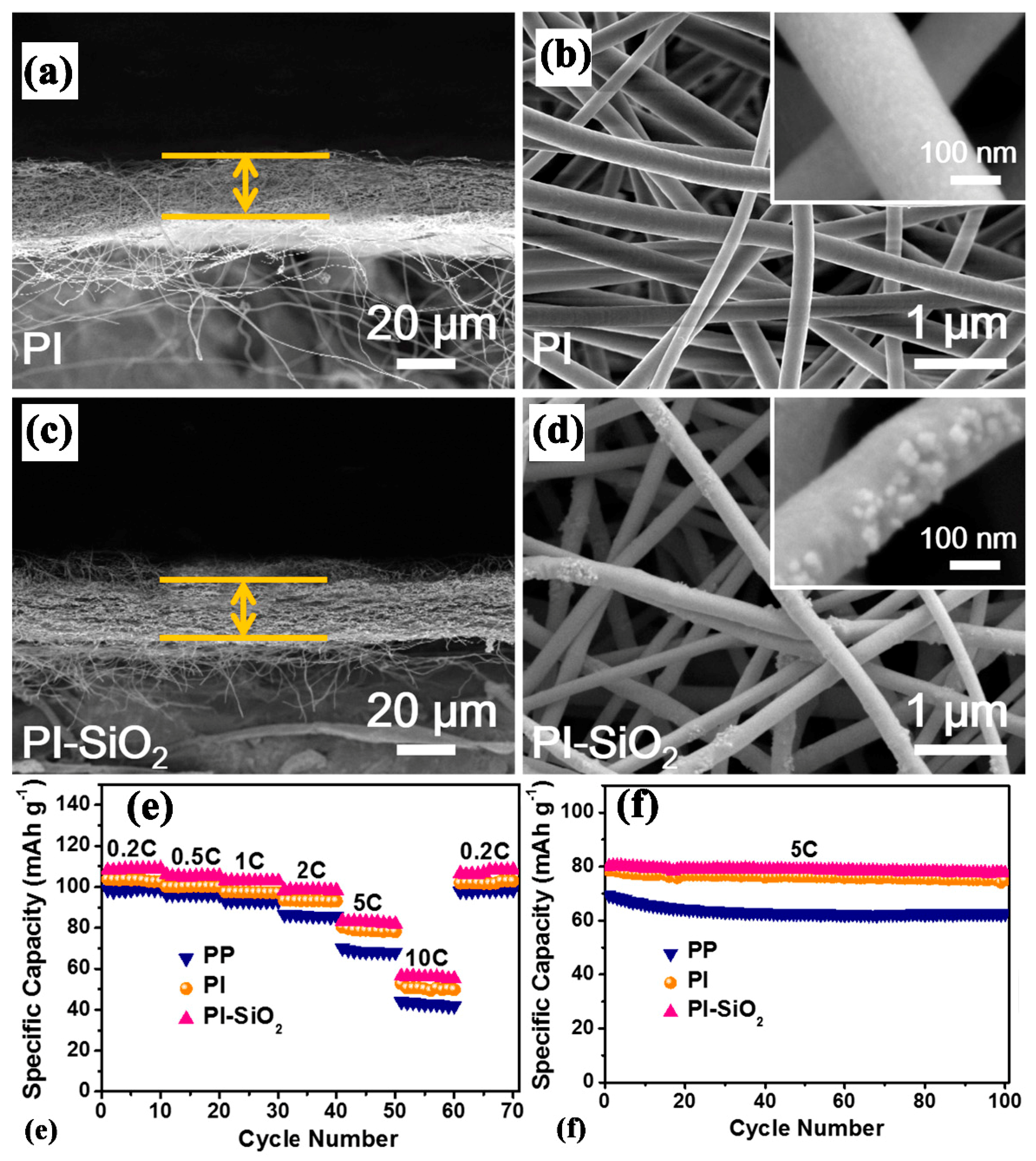
- Liang, X.; Yang, Y.; Jin, X.; Huang, Z.; Kang, F. The high performances of SiO2/Al2O3-coated electrospun polyimide fibrous separator for lithium-ion battery. J. Membr. Sci. 2015, 493, 1–7. [Google Scholar] [CrossRef]
- Chen, P.; Shen, J.; Wang, T.; Dai, M.; Si, C.; Xie, J.; Li, M.; Cong, X.; Sun, X. Zeolitic imidazolate framework-67 based separator for enhanced high thermal stability of lithium ion battery. J. Power Sources 2018, 400, 325–332. [Google Scholar] [CrossRef]
- Mi, W.; Sharma, G.; Dong, X.; Jin, Y.; Lin, Y.S. Electrode-supported thin α-alumina separators for lithium-ion batteries. J. Power Sources 2016, 305, 209–216. [Google Scholar] [CrossRef]
- Feng, G.; Li, Z.; Mi, L.; Zheng, J.; Feng, X.; Chen, W. Polypropylene/hydrophobic-silica-aerogel-composite separator induced enhanced safety and low polarization for lithium-ion batteries. J. Power Sources 2018, 376, 177–183. [Google Scholar] [CrossRef]
- Chao, C.-Y.; Feng, Y.-F.; Hua, K.; Li, H.; Wu, L.-J.; Zhou, Y.-S.; Dong, Z.-W. Enhanced wettability and thermal stability of polypropylene separators by organic-inorganic coating layer for lithium-ion batteries. J. Appl. Polym. Sci. 2018, 135, 46478. [Google Scholar] [CrossRef]
- Zhang, Z.; Yuan, W.; Li, L. Enhanced wettability and thermal stability of nano-SiO2/poly(vinyl alcohol)-coated polypropylene composite separators for lithium-ion batteries. Particuology 2018, 37, 91–98. [Google Scholar] [CrossRef]
- Xie, J.-D.; Fu, C.-C.; Liao, C.-C.; Juang, R.-S. Sol–gel deposition of silica nanospheres onto polymeric separators for improved performance of Li-ion batteries. J. Taiwan Inst. Chem. Eng. 2017, 81, 199–205. [Google Scholar] [CrossRef]
- Chen, W.; Shi, L.; Wang, Z.; Zhu, J.; Yang, H.; Mao, X.; Chi, M.; Sun, L.; Yuan, S. Porous cellulose diacetate-SiO2 composite coating on polyethylene separator for high-performance lithium-ion battery. Carbohydr. Polym. 2016, 147, 517–524. [Google Scholar] [CrossRef] [PubMed]
- Pi, J.-K.; Wu, G.-P.; Yang, H.-C.; Arges, C.G.; Xu, Z.-K. Separators with Biomineralized Zirconia Coatings for Enhanced Thermo- and Electro-Performance of Lithium-Ion Batteries. ACS Appl. Mater. Interfaces 2017, 9, 21971–21978. [Google Scholar] [CrossRef] [PubMed]
- Shi, C.; Dai, J.; Li, C.; Shen, X.; Peng, L.; Zhang, P.; Wu, D.; Sun, D.; Zhao, J. A modified ceramic-coating separator with high-temperature stability for lithium-ion battery. Polymers (Basel). 2017, 9, 159. [Google Scholar] [CrossRef] [PubMed]
- Jeon, H.; Jin, S.Y.; Park, W.H.; Lee, H.; Kim, H.-T.; Ryou, M.-H.; Lee, Y.M. Plasma-assisted water-based Al2O3 ceramic coating for polyethylene-based microporous separators for lithium metal secondary batteries. Electrochim. Acta 2016, 212, 649–656. [Google Scholar] [CrossRef]
- Lee, J.Y.; Lee, Y.M.; Bhattacharya, B.; Nho, Y.-C.; Park, J.-K. Separator grafted with siloxane by electron beam irradiation for lithium secondary batteries. Electrochim. Acta 2009, 54, 4312–4315. [Google Scholar] [CrossRef]
- Sohn, J.; Im, J.S.; Gwon, S.; Choi, J.; Shin, J.; Nho, Y.-C. Preparation and characterization of a PVDF-HFP/PEGDMA-coated PE separator for lithium-ion polymer battery by electron beam irradiation. Radiat. Phys. Chem. 2009, 78, 505–508. [Google Scholar] [CrossRef]
- Zhu, X.; Jiang, X.; Ai, X.; Yang, H.; Cao, Y. TiO2 ceramic-grafted polyethylene separators for enhanced thermostability and electrochemical performance of lithium-ion batteries. J. Memb. Sci. 2016, 504, 97–103. [Google Scholar] [CrossRef]
- Jiang, X.; Zhu, X.; Ai, X.; Yang, H.; Cao, Y. Novel Ceramic-Grafted Separator with Highly Thermal Stability for Safe Lithium-Ion Batteries. ACS Appl. Mater. Interfaces 2017, 9, 25970–25975. [Google Scholar] [CrossRef] [PubMed]
- Choi, Y.; Kim, J., II; Moon, J.; Jeong, J.; Park, J.H. Electron beam induced strong organic/inorganic grafting for thermally stable lithium-ion battery separators. Appl. Surf. Sci. 2018, 444, 339–344. [Google Scholar] [CrossRef]
- Liu, M.; Zhang, P.; Gou, L.; Hou, Z.; Huang, B. Enhancement on the thermostability and wettability of lithium-ion batteries separator via surface chemical modification. Mater. Lett. 2017, 208, 98–101. [Google Scholar] [CrossRef]
- Nho, Y.-C.; Sohn, J.-Y.; Shin, J.; Park, J.-S.; Lim, Y.-M.; Kang, P.-H. Preparation of nanocomposite γ-Al2O3/polyethylene separator crosslinked by electron beam irradiation for lithium secondary battery. Radiat. Phys. Chem. 2017, 132, 65–70. [Google Scholar] [CrossRef]
- Cho, J.; Jung, Y.C.; Lee, Y.S.; Kim, D.W. High performance separator coated with amino-functionalized SiO2 particles for safety enhanced lithium-ion batteries. J. Membr. Sci. 2017, 535, 151–157. [Google Scholar] [CrossRef]
- Mao, X.; Shi, L.; Zhang, H.; Wang, Z.; Zhu, J.; Qiu, Z.; Zhao, Y.; Zhang, M.; Yuan, S. Polyethylene separator activated by hybrid coating improving Li+ ion transference number and ionic conductivity for Li-metal battery. J. Power Sources 2017, 342, 816–824. [Google Scholar] [CrossRef]
- Liao, H.; Zhang, H.; Qin, G.; Hong, H.; Li, Z.; Lin, Y.; Li, L. Novel Core-Shell PS-co-PBA@SiO2 Nanoparticles Coated on PP Separator as “Thermal Shutdown Switch” for High Safety Lithium-Ion Batteries. Macromol. Mater. Eng. 2017, 302, 1700241. [Google Scholar] [CrossRef]
- Zheng, W.; Zhu, Y.; Na, B.; Lv, R.; Liu, H.; Li, W.; Zhou, H. Hybrid silica membranes with a polymer nanofiber skeleton and their application as lithium-ion battery separators. Compos. Sci. Technol. 2017, 144, 178–184. [Google Scholar] [CrossRef]
- Wang, Z.; Xiang, H.; Wang, L.; Xia, R.; Nie, S.; Chen, C.; Wang, H. A paper-supported inorganic composite separator for high-safety lithium-ion batteries. J. Membr. Sci. 2018, 553, 10–16. [Google Scholar] [CrossRef]
- Wu, D.; Deng, L.; Sun, Y.; Teh, K.S.; Shi, C.; Tan, Q.; Zhao, J.; Sun, D.; Lin, L. A high-safety PVDF/Al2O3 composite separator for Li-ion batteries via tip-induced electrospinning and dip-coating. RSC Adv. 2017, 7, 24410–24416. [Google Scholar] [CrossRef]
- Xiao, W.; Liu, J.; Yan, C. Nanofiber/ZrO2-based mixed matrix separator for high safety/high-rate lithium–ion batteries. Chem. Phys. Lett. 2017, 686, 134–139. [Google Scholar] [CrossRef]
- Li, W.; Li, X.; Yuan, A.; Xie, X.; Xia, B. Al2O3/poly(ethylene terephthalate) composite separator for high-safety lithium-ion batteries. Ionics (Kiel). 2016, 22, 2143–2149. [Google Scholar] [CrossRef]
- Jiang, F.; Nie, Y.; Yin, L.; Feng, Y.; Yu, Q.; Zhong, C. Core–shell-structured nanofibrous membrane as advanced separator for lithium-ion batteries. J. Membr. Sci. 2016, 510, 1–9. [Google Scholar] [CrossRef]
- Xiao, W.; Wang, J.; Wang, H.; Gong, Y.; Zhao, L.; Liu, J.; Yan, C. Hollow mesoporous silica sphere-embedded composite separator for high-performance lithium-ion battery. J. Solid State Electrochem. 2016, 20, 2847–2855. [Google Scholar] [CrossRef]
- Luo, D.; Chen, M.; Xu, J.; Yin, X.; Wu, J.; Chen, S.; Wang, L.; Wang, H. Polyphenylene sulfide nonwoven-based composite separator with superior heat-resistance and flame retardancy for high power lithium ion battery. Compos. Sci. Technol. 2018, 157, 119–125. [Google Scholar] [CrossRef]
- Xu, Q.; Wei, C.; Fan, L.; Peng, S.; Xu, W.; Xu, J. A bacterial cellulose/Al2O3 nanofibrous composite membrane for a lithium-ion battery separator. cellulose 2017, 1889–1899. [Google Scholar] [CrossRef]
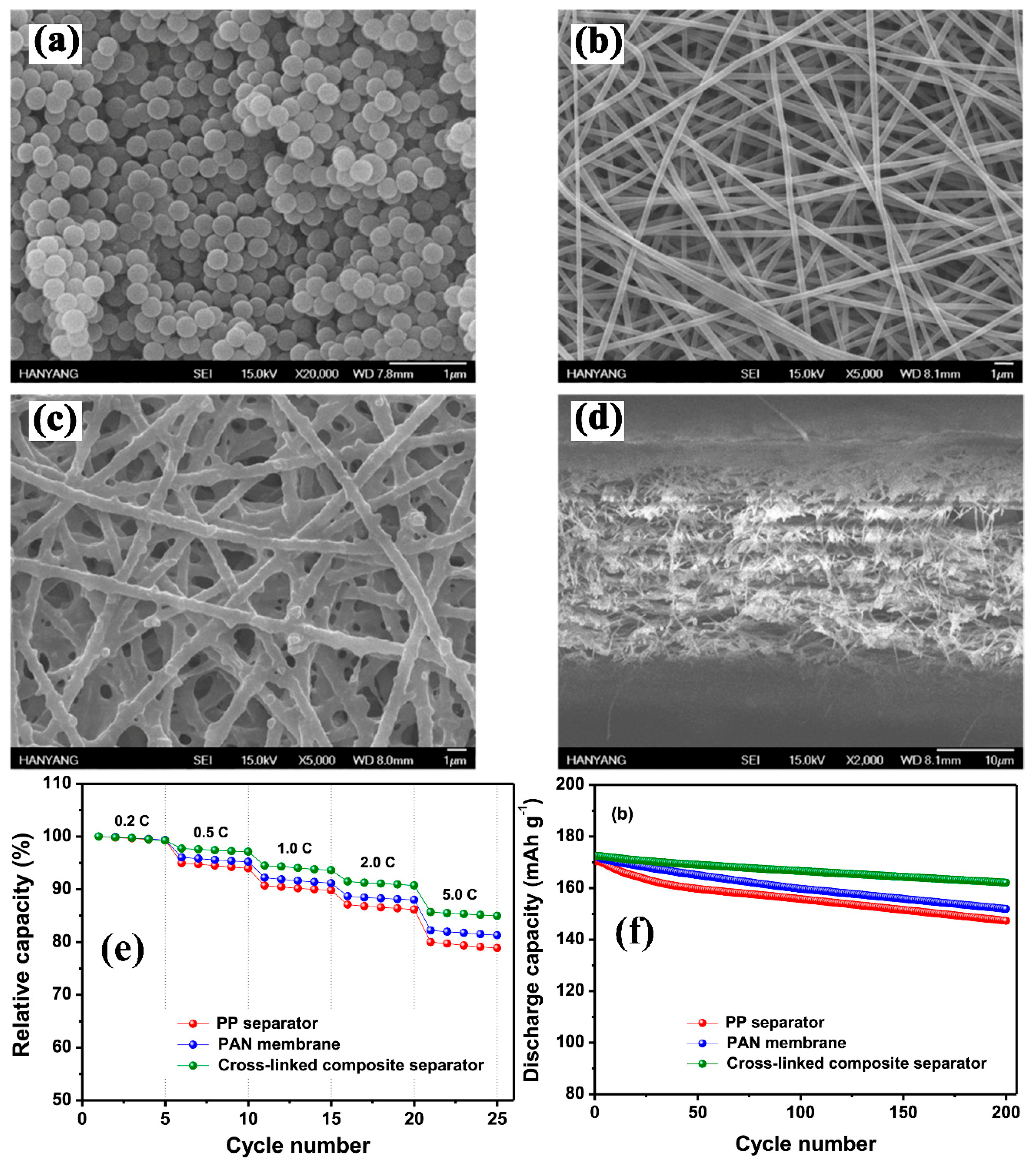
- Park, S.-R.; Jung, Y.-C.; Shin, W.-K.; Ahn, K.H.; Lee, C.H.; Kim, D.-W. Cross-linked fibrous composite separator for high performance lithium-ion batteries with enhanced safety. J. Membr. Sci. 2017, 527, 129–136. [Google Scholar] [CrossRef]
- Aravindan, V.; Vickraman, P.; Sivashanmugam, A.; Thirunakaran, R.; Gopukumar, S. Comparison among the performance of LiBOB, LiDFOB and LiFAP impregnated polyvinylidenefluoride-hexafluoropropylene nanocomposite membranes by phase inversion for lithium batteries. Curr. Appl. Phys. 2013, 13, 293–297. [Google Scholar] [CrossRef]
- Aravindan, V.; Vickraman, P.; Prem Kumar, T. ZrO2 nanofiller incorporated PVC/PVdF blend-based composite polymer electrolytes (CPE) complexed with LiBOB. J. Membr. Sci. 2007, 305, 146–151. [Google Scholar] [CrossRef]
- Aravindan, V.; Gnanaraj, J.; Madhavi, S.; Liu, H.-K. Lithium-Ion Conducting Electrolyte Salts for Lithium Batteries. Chem.- Eur. J. 2011, 17, 14326–14346. [Google Scholar] [CrossRef] [PubMed]
- Aravindan, V.; Vickraman, P.; Krishnaraj, K. Li+ ion conduction in TiO2 filled polyvinylidenefluoride-co-hexafluoropropylene based novel nanocomposite polymer electrolyte membranes with LiDFOB. Curr. Appl. Phys. 2009, 9, 1474–1479. [Google Scholar] [CrossRef]
- Nunes-Pereira, J.; Costa, C.M.; Lanceros-Méndez, S. Polymer composites and blends for battery separators: State of the art, challenges and future trends. J. Power Sources 2015, 281, 378–398. [Google Scholar] [CrossRef]
- Singh, V.; Joung, D.; Zhai, L.; Das, S.; Khondaker, S.I.; Seal, S. Graphene based materials: Past, present and future. Prog. Mater. Sci. 2011, 56, 1178–1271. [Google Scholar] [CrossRef]
- Shi, X.; Ma, N.; Wu, Y.; Lu, Y.; Xiao, Q.; Li, Z.; Lei, G. Fabrication and electrochemical properties of LATP/PVDF composite electrolytes for rechargeable lithium-ion battery. Solid State Ionics 2018, 325, 112–119. [Google Scholar] [CrossRef]
- Costa, C.M.; Kundu, M.; Cardoso, V.F.; Machado, A.V.; Silva, M.M. Silica/poly(vinylidene fluoride) porous composite membranes for lithium- ion battery separators. J. Membr. Sci. 2018, 564, 842–851. [Google Scholar] [CrossRef]
- Wang, X.; Xu, G.; Wang, Q.; Lu, C.; Zong, C.; Zhang, J.; Yue, L.; Cui, G. A phase inversion based sponge-like polysulfonamide/SiO2 composite separator for high performance lithium-ion batteries. Chin. J. Chem. Eng. 2018, 26, 1292–1299. [Google Scholar] [CrossRef]
- Cohen, C.; Tanny, G.B.; Prager, S. Diffusion-controlled formation of porous structures in ternary polymer systems. J. Polym. Sci. Polym. Phys. Ed. 1979, 17, 477–489. [Google Scholar] [CrossRef]
- Yong, S.K.; Hyo, J.K.; Un, Y.K. Asymmetric membrane formation via immersion precipitation method. I. Kinetic effect. J. Membr. Sci. 1991, 60, 219–232. [Google Scholar] [CrossRef]
- Ali, S.; Tan, C.; Waqas, M.; Lv, W.; Wei, Z.; Wu, S.; Boateng, B.; Liu, J.; Ahmed, J.; Xiong, J.; et al. Highly Efficient PVDF-HFP/Colloidal Alumina Composite Separator for High-Temperature Lithium-Ion Batteries. Adv. Mater. Interfaces 2018, 5, 1701147. [Google Scholar] [CrossRef]
- Nunes-Pereira, J.; Kundu, M.; Gören, A.; Silva, M.M.; Costa, C.M.; Liu, L.; Lanceros-Méndez, S. Optimization of filler type within poly(vinylidene fluoride-co-trifluoroethylene) composite separator membranes for improved lithium-ion battery performance. Compos. Part B 2016, 96, 94–102. [Google Scholar] [CrossRef]
- Cui, J.; Liu, J.; He, C.; Li, J.; Wu, X. Composite of polyvinylidene fluoride–cellulose acetate with Al(OH)3 as a separator for high-performance lithium ion battery. J. Membr. Sci. 2017, 541, 661–667. [Google Scholar] [CrossRef]
- Zhang, Y.; Wang, Z.; Xiang, H.; Shi, P.; Wang, H. A thin inorganic composite separator for lithium-ion batteries. J. Membr. Sci. 2016, 509, 19–26. [Google Scholar] [CrossRef]
- Solarajan, A.K.; Murugadoss, V.; Angaiah, S. High performance electrospun PVdF-HFP/SiO2 nanocomposite membrane electrolyte for Li-ion capacitors. J. Appl. Polym. Sci. 2017, 134, 45177. [Google Scholar] [CrossRef]
- Angulakshmi, N.; Stephan, A.M. Electrospun Trilayer Polymeric Membranes as Separator for Lithium–ion Batteries. Electrochim. Acta 2014, 127, 167–172. [Google Scholar] [CrossRef]
- Chen, W.; Liu, Y.; Ma, Y.; Yang, W. Improved performance of lithium ion battery separator enabled by co-electrospinnig polyimide/poly(vinylidene fluoride-co-hexafluoropropylene) and the incorporation of TiO2-(2-hydroxyethyl methacrylate). J. Power Sources 2015, 273, 1127–1135. [Google Scholar] [CrossRef]
- Bhute, M.V.; Mahant, Y.P.; Kondawar, S.B. Materials NanoScience Titanium dioxide/poly (vinylidene fluoride) hybrid polymer composite nanofibers as potential separator for lithium ion battery. J. Mater. Nanosci. 2017, 4, 6–12. [Google Scholar]
- Zhang, J.; Xiang, Y.; Jamil, M.I.; Lu, J.; Zhang, Q.; Zhan, X.; Chen, F. Polymers/zeolite nanocomposite membranes with enhanced thermal and electrochemical performances for lithium-ion batteries. J. Membr. Sci. 2018, 564, 753–761. [Google Scholar] [CrossRef]
- Smith, S.A.; Williams, B.P.; Lak, Y. Effect of polymer and ceramic morphology on the material and electrochemical properties of electrospun PAN/polymer derived ceramic composite nano fi ber membranes for lithium ion battery separators. J. Membr. Sci. 2017, 526, 315–322. [Google Scholar] [CrossRef]
- Fang, C.; Yang, S.; Zhao, X.; Du, P.; Xiong, J. Electrospun montmorillonite modified poly(vinylidene fluoride) nanocomposite separators for lithium-ion batteries. Mater. Res. Bull. 2016, 79, 1–7. [Google Scholar] [CrossRef]
- Li, H.; Wu, D.; Wu, J.; Dong, L.-Y.; Zhu, Y.-J.; Hu, X. Flexible, High-Wettability and Fire-Resistant Separators Based on Hydroxyapatite Nanowires for Advanced Lithium-Ion Batteries. Adv. Mater. 2017, 29, 1703548. [Google Scholar] [CrossRef] [PubMed]
- Zhao, H.; Deng, N.; Yan, J.; Kang, W.; Ju, J.; Wang, L. E ff ect of OctaphenylPolyhedral oligomeric silsesquioxane on the electrospun Poly-m-phenylene isophthalamid separators for lithium-ion batteries with high safety and excellent electrochemical performance. Chem. Eng. J. 2019, 356, 11–21. [Google Scholar] [CrossRef]
- Wang, Y.; Wang, S.; Fang, J.; Ding, L.-X.; Wang, H. A nano-silica modified polyimide nanofiber separator with enhanced thermal and wetting properties for high safety lithium-ion batteries. J. Membr. Sci. 2017, 537, 248–254. [Google Scholar] [CrossRef]
- Chen, W.; Liu, Y.; Ma, Y.; Liu, J.; Liu, X. Improved performance of PVdF-HFP/PI nanofiber membrane for lithium ion battery separator prepared by a bicomponent cross-electrospinning method. Mater. Lett. 2014, 133, 67–70. [Google Scholar] [CrossRef]
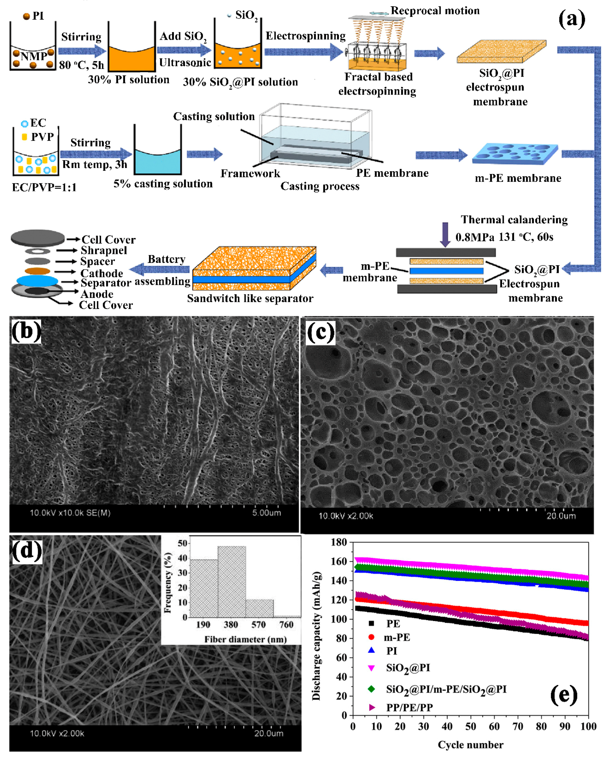
- Liu, J.; Liu, Y.; Yang, W.; Ren, Q.; Li, F.; Huang, Z. Lithium ion battery separator with high performance and high safety enabled by tri-layered SiO2 @PI/m-PE/SiO2 @PI nanofiber composite membrane. J. Power Sources 2018, 396, 265–275. [Google Scholar] [CrossRef]
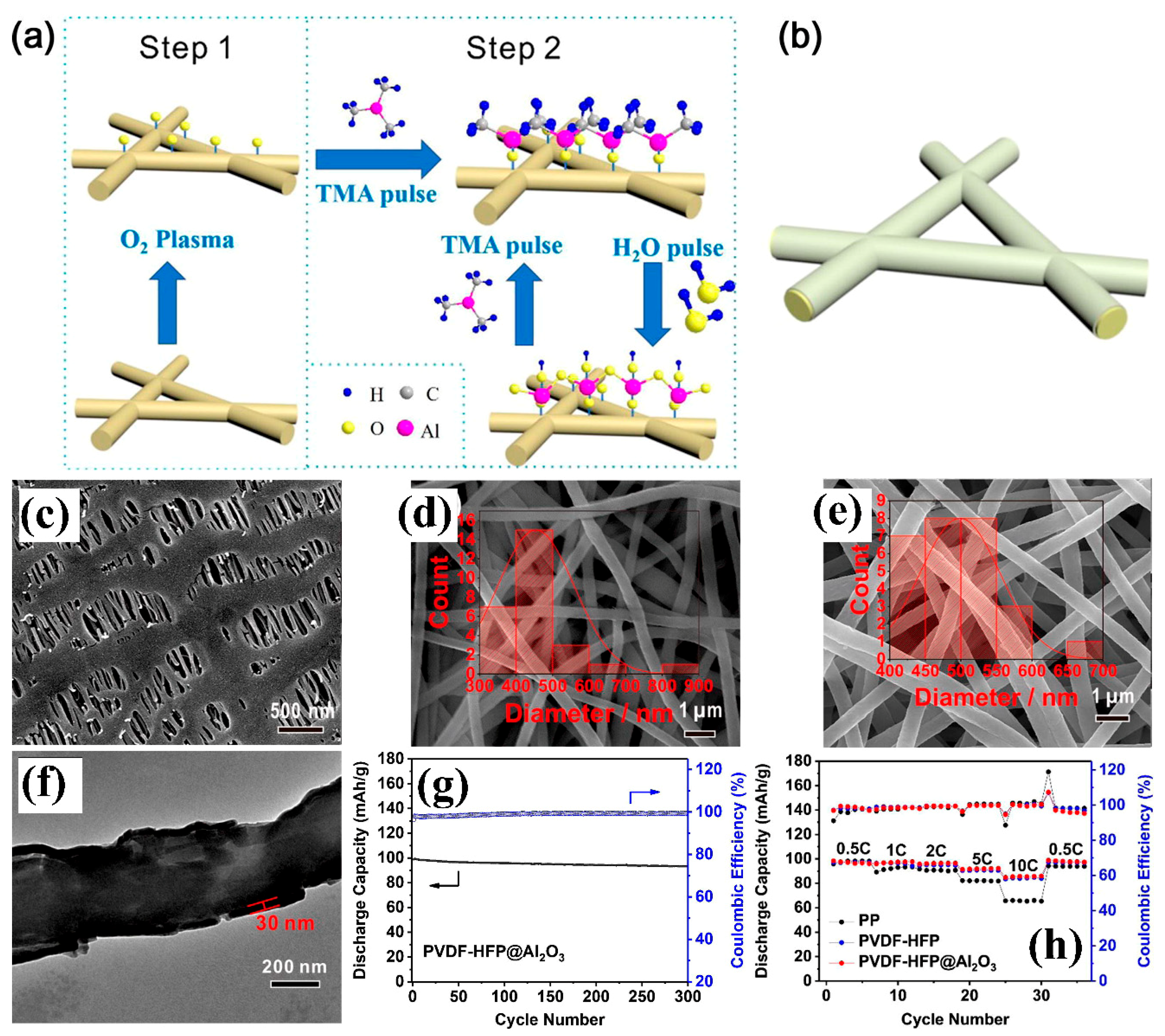
- Shen, X.; Li, C.; Shi, C.; Yang, C.; Deng, L.; Zhang, W.; Peng, L.; Dai, J.; Wu, D.; Zhang, P.; et al. Core-shell structured ceramic nonwoven separators by atomic layer deposition for safe lithium-ion batteries. Appl. Surf. Sci. 2018, 441, 165–173. [Google Scholar] [CrossRef]
- Jiang, Y.; Ding, Y.; Zhang, P.; Li, F.; Yang, Z. Temperature-dependent on/off PVP@TiO2 separator for safe Li-storage. J. Membr. Sci. 2018, 565, 33–41. [Google Scholar] [CrossRef]
- Yanilmaz, M.; Lu, Y.; Zhu, J.; Zhang, X. Silica/polyacrylonitrile hybrid nano fi ber membrane separators via sol- gel and electrospinning techniques for lithium-ion batteries. J. Power Sources 2016, 313, 205–212. [Google Scholar] [CrossRef]


| Substrate/Inorganic Particles | Polymer Binder | Fabrication Method | Composite Separator Thickness (μm)/Electrolyte | Ion Conduction (σ)/Thermal Stability/Shrinkage Percentage | Cathode/Anode | Electrochemical Performance | Refs. |
|---|---|---|---|---|---|---|---|
| PE/Al2O3 | Polyimide | Automatic coating machine | 26/- | 0.70 mS cm−1/160 °C/0% | LiMn2O4/Li | In 3.0 V to 4.2 V 0.5 C ≈ 107 mAh g−1 1 C ≈ 105 mAh g−1 2 C ≈ 101 mAh g−1 5 C ≈ 92.5 mAh g−1 | [49] |
| PP/Zeolite | PVDF | Dip coating | 22/1 M LiPF6− EC-DEC-DMC (1:1:1 V:V:V) | - | Li4Ti5O12/Li | Enhanced electrolyte uptake, electrolyte retention and stable capacity at different rate. | [50] |
| PE/α-Al2O3 | - | Dip coating | 32–35/1 M LiPF6− EC-DEC (1:1 V:V) | -/140 °C/60% | LiCoO2/Li | In 3.0 to 4.3 V Thermally stable, 244.4% electrolyte uptake, 87% capacity after 100 cycles for 0.5 C rate. | [51] |
| PE/CeO2 | P(MMA-BA-AN-St) | One side coating | 75/1M LiPF6− EMC-EC-DEC (5:3:2 V:V:V) | -/2.5 mS cm−1/135 °C/0% | LiNi0.5Mn1.5O4/Li | In 3.0 to 5.0 V 0.2 C ≈ 131 mAh g−1 0.2 C ≈ 125 mAh g−1 0.5 C ≈ 120 mAh g−1 1 C ≈ 119 mAh g−1 | [52] |
| PE/Al2O3 | BA+ MMA | Automatic bar coating machine | 16/1 M LiPF6− EC-DEC (1:1 V:V) | -/0.68 mS cm−1/130 °C/1.6% | LiCoO2/Graphite | In 3.0 to 4.2 V 0.2 C ≈ 132 mAh g−1 0.5 C ≈ 125 mAh g−1 1.0 C ≈ 119 mAh g−1 2 C ≈ 101 mAh g−1 5 C ≈ 53 mAh g−1 | [65] |
| PE/Nano-ppy/OMMT | PVDF | Dip coating | -/1 M LiPF6 DEC-EC-EMC (1:1:1 V:V:V) | -/4.31 mS cm−1/80 °C/0% | LiNi1/3Co1/3Mn1/3O2/Li | In 2.7 to 4.2 V 0.5 C ≈ 125.9 mAh g−1 After 100 cycles At 80 °C 80% capacity retention | [53] |
| PE/Al2O3 | PVdF-HFP/CMC | Dip coating | 12/1 M LiPF6− EC-DEC-PC-EMC (2:3:1:3 V:V:V) | 9.3 mS cm−1/110 °C/0% | LiCoO2/graphite | In 3.0 to 4.35 V 0.2 C ≈ 162mAh g−1 0.5 C ≈ 161mAh g−1 1.0 C ≈ 158mAh g−1 1.5 C ≈ 153mAh g−1 2 C ≈ 144mAh g−1 | [62] |
| PE/Al2O3 | CMC | Bar coating on one side | -/1 M LiPF6− EC-EMC (3:7 V:V) | 0.846 mS cm−1/140 °C/0% | LiMn2O4/Graphite | In 3.0 to 4.3 V 0.5 C ≈ 109 mAh g−1 1.0 C ≈ 108 mAh g−1 2.0 C ≈ 99 mAh g−1 5.0 C ≈ 90 mAh g−1 7.0 C ≈ 80 mAh g−1 10 C ≈ 70 mAh g−1 15 C ≈ 50 mAh g−1 20 C ≈ 30 mAh g−1 | [63] |
| PE/AlOOH | PVA | One side dip coating | 17.15/1 M LiPF6− EC-DEC (1:1 V:V) | 6.56 mS cm−1/180 °C/3% | Li4Ti5O12/Li | In 1.0 to 2.5 V 0.2 C ≈ 152mAh g−1 0.5 C ≈ 150mA hg−1 1.0 C ≈ 142mAh g−1 2.0 C ≈ 130mAh g−1 | [64] |
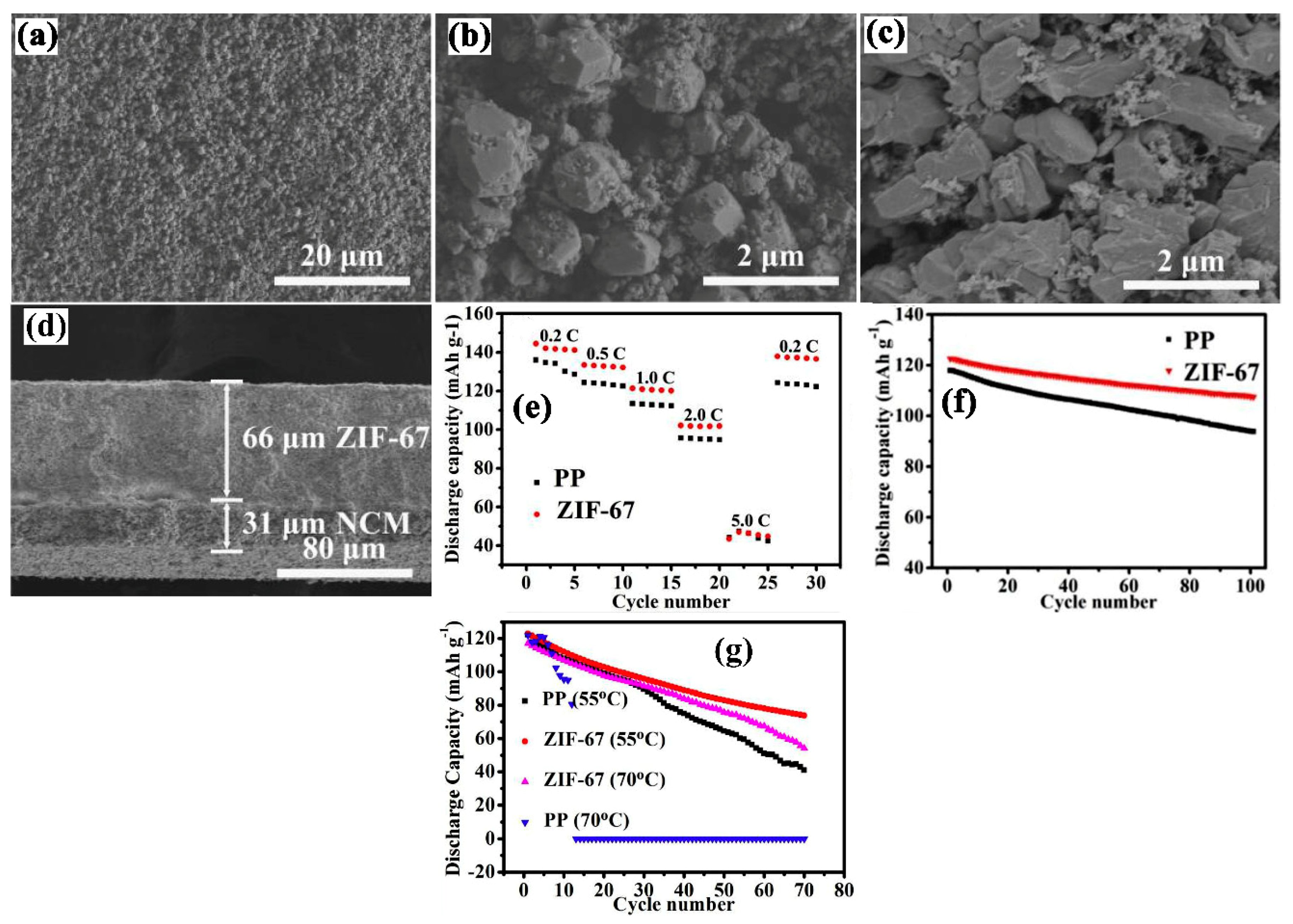
| NCM Cathode/Zeolitic imidazolate | PVDF | Blade coating | 66/1 M LiPF6− EC-DMC-DEC (1:1:1 V:V:V) | 1.64 mS cm−1/100 °C/0% | LiNi0.5Co0.2Mn0.3O2(NCM)/Li | In 3.0 to 4.2 V 0.2 C ≈ 142 mAh g−1 0.5 C ≈ 133 mAh g−1 1.0 C ≈ 121 mAh g−1 2.0 C ≈ 102 mAh g−1 5.0 C ≈ 44 mAh g−1 | [69] |
| LTO cathode/Alumina | PVA | Blade coating | 25/1 M LiPF6− EC-DEC-DMC (1:1:1, V:V:V) | 2.39 mS cm−1/120 °C/0% | LTO/Li | In 1.0 to 2.5 V 0.2 C ≈ 171 mAh g−1 0.5 C ≈ 165 mAh g−1 1.0 C ≈ 150 mAh g−1 2.0 C ≈ 0 mAh g−1 | [70] |
| PP/SiO2 | PVDF | Dip coating | -/1 M LiPF6− EC-DMC (1:1 V:V) | 0.63 mS cm−1/160 °C/24.5% | LiFePO4/Li | In 2.0 to 4.3 V 0.2 C ≈ 158 mAh g−1 0.5 C ≈ 150 mAh g−1 1.0 C ≈ 141 mAh g−1 2.0 C ≈ 133 mAh g−1 4 C ≈ 123 mAh g−1 8 C ≈ 101 mAh g−1 | [71] |
| PP/SiO2 | r-glycidoxy propyl trimethoxy silane | Dip coating | -/- | 0.55 mS cm−1/160 °C/25% | LiCoO2/Graphite | In 2.5 to 4.2 V 0.2 C ≈ 5.1mAh g−1 0.5 C ≈ 4.5mAh g−1 1.0 C ≈ 4mAh g−1 2 C ≈ 2.5mAh g−1 | [72] |
| PP/SiO2 | PVA | Dip Coating | -/1 M LiPF6− EC-DMC-DEC (1:1:1, V:V:V) | -/1.26 mS cm−1/170 °C/8.3% | LiCoO2/Li | In 3.0 to 4.2 V 0.2 C ≈ 131.8 mAh g−1 0.5 C ≈ 131 mAh g−1 1.0 C ≈ 129 mAh g−1 2.0 C ≈ 119 mAh g−1 | [73] |
| PP/PE/PP/SiO2 | PVDF-HFP | Dip coating | -/1 M LiPF6− EC-PC-DMC (1:1:1 V:V:V) | -/180 °C/38% | LTO/Li | In 1 to 3 V 0.1 C ≈ 161 mAh g−1 1 C ≈ 152 mAh g−1 | [74] |
| PE/SiO2 | Cellulose diacetate | Coating by Sol-gel method | 16/1 M LiPF6− EC-DEC-EMC (1:1:1 W:W:W) | -/0.624 mS cm−1/- | LiCoO2/Li | In 3.0 to 4.2 V 0.2 C ≈ 153 mAh g−1 0.5 C ≈ 141 mAh g−1 1 C ≈ 120 mAh g−1 2 C ≈ 91 mAh g−1 3 C ≈ 79 mAh g−1 | [75] |
| PE/Al2O3 | CMC | One side Dip coating | 27/1.15 M LiPF6− EC-EMC (3:7 V:V) | 0.758 mS cm−1/140/0% | LiMn2O4/graphite | In 3.0 to 4.4 V 86% capacity retention after 100 cycles at 1 C. | [66] |
| PE/Al2O3 | CMC | Dip coating | 24/1 M LiPF6− EC-DMC-DEC (1:1:1 V:V:V) | 0.71 mS cm−1/200 °C/0% | LiMn2O4/Li | In 3 to 4.2 V 0.5 C ≈ 106 mAh g−1 1 C ≈ 104 mAh g−1 2 C ≈ 97.5 mAh g−1 4 C ≈ 85 mAh g−1 | [77] |
| PP/ZrO2 | - | Dip coating | -/1 M LiPF6− EC-DEC-DMC (1:1:1 V:V:V) | 1.61 mS cm−1/140 °C/0% | LiFePO4/Li | In 3.0 to 4.2 V 0.1 C ≈ 159.4 mAh g−1 0.2 C ≈ 150 mAh g−1 1.0 C ≈ 137.5 mAh g−1 2.0 C ≈ 125 mAh g−1 5.0 C ≈ 100 mAh g−1 | [76] |
| PE/Al2O3 | CMC | a wire bar (Mayer bar)-coating process using | 26/1M LiPF6– EC-EMC (1:1 V:V) | 0.967–1.182 mS cm−1/140 °C/0% | LiMn2O4/Li | In 3.0 to 4.4 V No shrinkage at 140 °C Stable capacity for 100 cycles as compared to bare PE separator | [78] |
| PE/TiO2 | - | Grafting by electron beam radiation | -/1M LiPF6– EC-DEC-DMC (1:1:1 V:V) | 0.32–0.50 mS cm−1/150 °C/36% | LiFePO4/Graphite | In 3.0 to 4.0 V No shrinkage at 150 °C Slightly better capacity retention as compare to PE separator | [81] |
| PE/Al2O3 | - | Grafting by electron beam radiation | 16/1M LiP6– EC-DEC-EMC (1:1:1, V:V:V) | 0.53 mS cm−1/150 °C/0% | LiFePO4/graphite | In 2.0 to 4.0 V 0.2 C ≈ 125 mAh g−1 0.5 C ≈ 121 mAh g−1 1 C ≈ 115 mAh g−1 2 C ≈ 102 mAh g−1 5 C ≈ 80 mAh g−1 | [82] |
| PE/SiO2 | - | Coating by grafting | 1M LiPF6– EC-DEC- EMC (1:1:1, v:v:v) | 0.8164 mS cm−1/150 °C/0% | LiCoO2/Graphitized mesocarbon microbead | In 3 to 4.3 V 0.2 C ≈ 149 mAh g−1 0.5 C ≈ 146 mAh g−1 1 C ≈ 142 mAh g−1 1.5 C ≈ 135 mAh g−1 2 C≈130 mAh g−1 3 C ≈ 89 mAh g−1 4 C ≈ 60 mAh g−1 5 C ≈ 45 mAh g−1 7 C ≈ 29 mAh g−1 | [83] |
| PP/SiO2 | - | Grafting and dip coating | 28/- | 1.43 mS cm−1/150 °C/12% | - | 0.2 C ≈ 175 mAh g−1 0.5 C ≈ 164 mAh g−1 1 C ≈ 130 mAh g−1 2 C ≈ 85 mAh g−1 | [84] |
| PE/Al2O3 | PVDF-HFP | Dip coating and after electron beam radiation | -/1M LiClO4 EC-DEC (1:1 V:V) | 1.3 mS cm−1/-/0% | LiCoO4/MCMB graphite | In 3.0–4.2 V 99% capacity retention after 100 cycles at 0.5 C rate. | [85] |
| PE/SiO2 | PVDF-HFP | Dip coating | 25/1.15M LiPF6– EC-EMC (3:7, V:V) | 0.81 mS cm−1/130 °C/0% | LiNi1/3CO1/3Mn1/3O2/(MCMB) graphite | In 3.0 to 4.5 V Stable cycling performance at 0.5C rate with minimal drop of capacity after 200 cycles. | [86] |
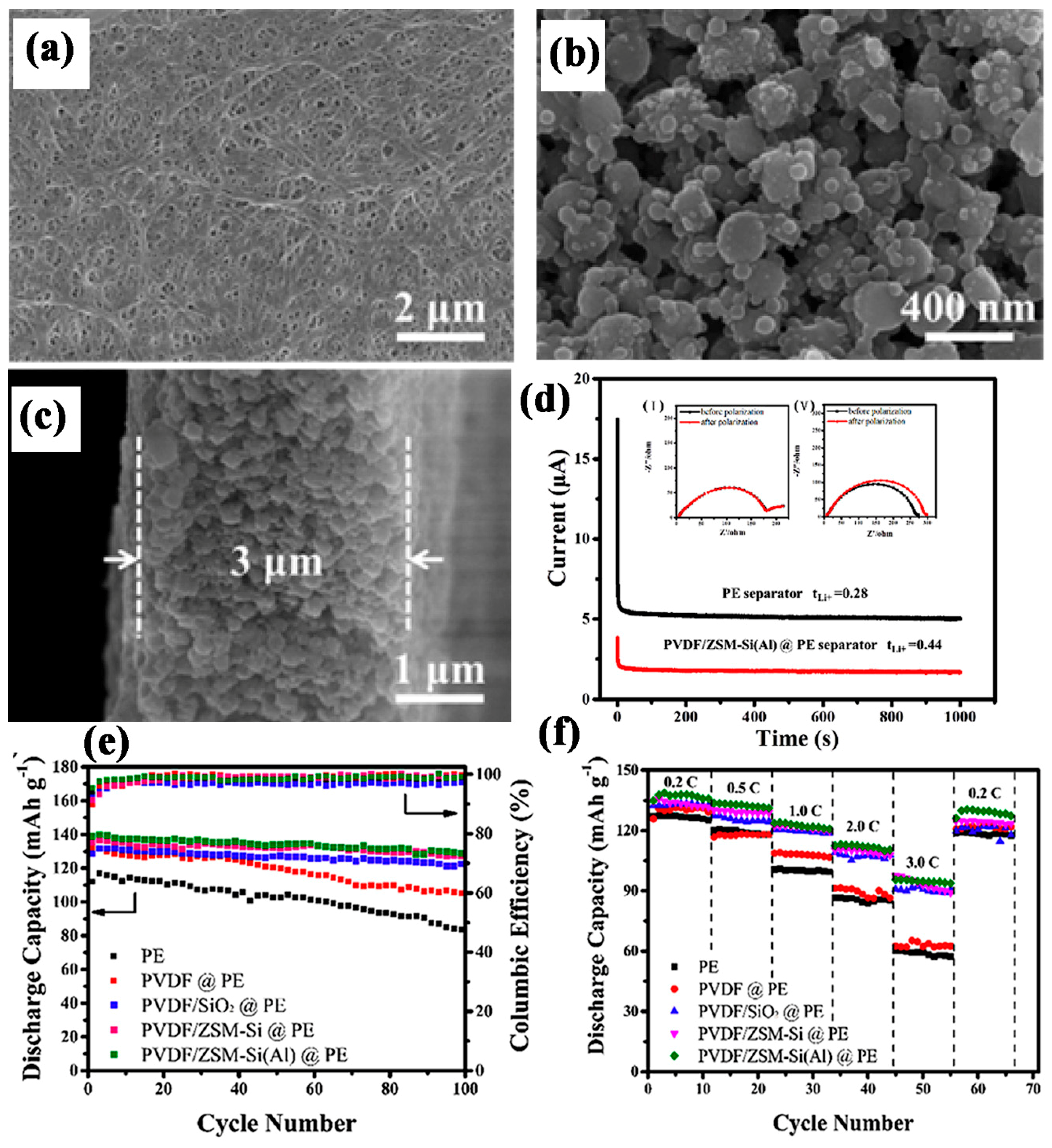
| PE/Al-SiO2 | PVDF | Dip coating | 18/1M LiPF6– EC-EMC-DEC (1:1:1, V:V:V) | 0.30–0.54 mS cm−1/130 °C/0% | LiCoO2/Li | In 3.0 to 4.2 V High lithium transference number 0.30-0.44. 95% capacity retention after 100 cycles at 0.2 C | [87] |
| PP/PS-b-PBA@SiO2 | HEC | Spray coating | - | 0.65 mS cm−1/160 °C/2% | LiFePO4/Li | In 2.75 to 4.2 0.5 C ≈ 145 mAh g−1 1 C ≈ 140 mAh g−1 5 C ≈ 134 mAh g−1 10 C ≈ 120 mAh g−1 | [88] |
| PVDF/PAN/SiO2 | PVDF | Dip coating | -/1 M LiPF6− EC-DMC-EMC (1:1:1, V:V:V) | 1.50–1.68 mS cm−1/200 °C/0% | LiFePO4/Li | In 2.5 to 4.5 V 0.2 C ≈ 151 mAh g−1 0.5 C ≈ 147 mAh g−1 1 C ≈ 138 mAh g−1 2 C≈126 mAh g−1 5 C ≈ 104 mAh g−1 | [89] |
| Cellulose paper/Al2O3 | CMC/PEG | Spray coating | 48/1 M LiPF6− EC-DEC (1:1 W:W) | 1.64 mS cm−1/130 °C/0% | LiCoO2/Graphite | In 3.0–4.35 V 0.5 C ≈ 152 mAh g−1, 1 C ≈ 150 mAh g−1 2 C ≈ 142 mAh g−1 4 C ≈ 123 mAh g−1 8 C ≈ 95 mAh g−1 | [90] |
| PVDF/Al2O3 | PEO | Dip coating | 74/1 M LiPF6− EC-DEC-DMC (1:1:1 W:W:W) | 2.23 mS cm−1/140 °C/2% | LiMn2O4/graphite | In 0.2–4.2 V 0.5 C ≈ 121 mAh g−1 1.0 C ≈ 119.1 mAh g−1 2.0 C ≈ 115 mAh g−1 4.0 C ≈ 110 mAh g−1 | [91] |
| PVA/ZrO2 | Bacterial cellulose | Deposition method | 25/1 M LiPF6− EC-DEC (1:1, V:V) | 2.14 mS cm−1/150 °C/3 % | LiFePO4/Li | In 2.5–4.2 V 0.5 C ≈ 144 mAh g−1 2.0 C ≈ 117 mAh g−1 8.0 C ≈ 81 mAhg−1 32 C ≈ 48 mAhg−1 64 C ≈ 20 mAhg−1 | [92] |
| PET/Al2O3 | PAAS | Dip coating | 25/1 M LiPF6− EC-EMC-DEC (1:1:1 V:V:V) | 1.13 mS cm−1/150 °C/0 % | LiNi1/3Co1/3Mn1/3O2/LiCoO2/Li | In 3.0 to 4.3 V 1 C ≈ 140 mAh g−1 2 C ≈ 130 mAh g−1 5 C ≈ 112 mAh g−1 10 C ≈ 97 mAh g−1 15 C ≈ 80 mAh g−1 20 C ≈ 64 mAh g−1 | [93] |
| BC/SiO2 | - | Sol-gel coating | 76.1/1 M LiPF6− EC-DEC (1:1 W:W) | 18.5 mS cm−1/200 °C/0 % | LiFePO4/Li | In 2.50–4.20 V 0.2 C ≈ 142 mAh g−1 0.5 C ≈ 120 mAh g−1 1 C ≈ 105 mAh g−1 2 C ≈ 90 mAh g−1 3 C ≈ 70 mAh g−1 5 C ≈ 50 mAh g−1 | [94] |
| PET/Hollow silica | PVDF-HFP | Dip coating | 22/1 M LiPF6− EC-DEC (1:1, V:V) | 2.57 mS cm−1/150 °C/0% | LiFePO4/Li | In 2.5–4.2 V 0.5 C ≈ 141 mAhg−1 1 C ≈ 137 mAhg−1 2 C ≈ 127 mAhg−1 3 C ≈ 112 mAhg−1 8 C ≈ 90 mAhg−1 | [95] |
| PPS/SiO2 | PVDF-HFP | Dip coating | 114/1 M LiPF6− EC-DEC (1:1, V:V) | 1.02 mS cm−1/250 °C/0% | LiFePO4/Li | 0.2 C ≈ 145 mAh g−1 0.5 C ≈ 140 mAh g−1 1 C ≈ 135 mAh g−1 2 C ≈ 83 mAh g−1 | [96] |
| BC/Al2O3 | - | Dip coating | 30/1 M LiPF6− EC-DMC-DEC (1:1:1, V:V:V) | 4.91 mS cm−1/150 °C/0% | LiFePO4/Li | In 2.5–4.2 V 0.2 C ≈ 160 mAh g−1 0.5 C ≈ 140 mAh g−1 1 C ≈ 130 mAh g−1 | [97] |
| PAN/SiO2 | TEGDA | Dip Coating | 35/1.15 M LiPF6− EC-EMC-DEC (3:5:2, V:V:V) | 2.1 mS cm−1/200 °C/0% | LiNi0.6Co0.6Mn0.2O2/Graphite | In 2.6–4.3 V Initial discharge capacity 172.5 mAh g−1 Final discharge capacity 162.1 mA h g−1 After 100 cycles. | [98] |
| PVDF/LATP | - | Casting method | -/1 M LiPF6− EC-EMC-DMC (1:1:1, V:V:V) | -/0.967 mS cm−1/- | LiFePO4Li | In 2.5–4.2 V Optimum ratio (LATP:PVDF 2:1) 0.1 C ≈ 163.5 mAh g−1 0.2 C ≈ 155 mAh g−1 0.5 C ≈ 150 mAh g−1 1 C ≈ 141 mAh g−1 | [105] |
| PVDF/SiO2 | - | Phase inversion | -/1 M LiPF6− EC-DMC (1:1, V:V) | -/0.9 mS cm−1/- | LiFePO4Li | In 2.5–4.2 V 0.1 C ≈ 150 mAh g−1 0.2 C ≈ 149 mAh g−1 0.5 C ≈ 140 mAh g−1 10 C ≈ 128mAh g−1 2 C ≈ 119mAh g−1 | [106] |
| PSA/SiO2 | - | Phase inversion | 40/1 M LiPF6− EC-DMC (1:1, V:V) | 0.748 mS cm−1/150 °C/0% | LiCoO2/Li | 0.2 C ≈ 146 mAh g−1 0.5 C ≈ 132 mAh g−1 2 C ≈ 113 mAh g−1 5 C ≈ 95 mAh g−1 10 C ≈ 70 mAh g−1 | [107] |
| PVDF-HFP/Al2O3 | - | Solvent evaporation method | 40–45/1 M LiPF6− EC-DMC-EMC-DMC +2% VC | 0.7 mS cm−1/150 °C/4.5% | LiFePO4/Li | In 2.5–4.2 V 0.2 C ≈ 155 mAh g−1 0.5 C ≈ 152 mAh g−1 1 C ≈ 139 mAh g−1 2 C ≈ 120 mAh g−1 | [110] |
| P(VDF-TrFE) P(VDF-TrFE) 4% MMT 16% NaY 16% BaTiO3 0.1%MWCNT | - | Solvent casting method | -/1 M LiTFSI PC | -/0.32 mS cm−1/- 0.36 mS cm−1 0.39 mS cm−1 0.64 mS cm−1 0.33 mS cm−1 | LiFePO4/Li | For 4% MMT 0.1 C-175 mAh g−1 0.2 C ≈ 169 mAh g−1 0.5 C ≈ 157 mAh g−1 1 C ≈ 140 mAh g−1 2 C ≈ 95 mAh g−1 | [111] |
| PVDF/CA/Al(OH)2 | - | Phase inversion | -/1 M LiPF6− EC-DMC-EMC (1:1:1, W:W:W) | 2.85 mS cm−1/160 °C/4.6 % | LiCoO2/Li | In 3.0–4.2 V 0.1 C ≈ 158 mAh g−1 0.2 C ≈ 155 mAh g−1 0.5 C ≈ 151 mAh g−1 1 C ≈ 149 mAh g−1 2 C ≈ 145 mAh g−1 4 C ≈ 135 mAh g−1 8 C ≈ 128.28 mAh g−1 | [112] |
| SBR/Al2O3 | - | Phase inversion method | 37/1 M LiPF6− EC-DMC (1:1, W:W) | 0.93 mS cm−1/130 °C/0 % | LiNi1/3Co1/3Mn1/3O2/graphite | 0.5 C ≈ 155 mAh g−1 1 C ≈ 151 mAh g−1 2 C ≈ 148 mAh g−1 4 C ≈ 140 mAh g−1 8 C ≈ 128 mAh g−1 | [113] |
| PVDF/TiO2 | - | Electrospinning | 50/1 M LiPF6− EC-DEC (1:1 V:V) | -/4.15 mS cm−1/- | - | High electrolyte uptake, high ion conductivity, wide electrochemical window | [117] |
| PC4SA-co-PMMA-co-PMPS/ZCM-5 | - | Electrospinning | -/1 M LiPF6− EC-EMC-DEC (1:1:1, V:V:V) | 1.72 mS cm−1/150 °C/0% | LiFePO4/Li | In 2.5–4.2 V 0.1 C ≈ 153 mAh g−1 0.2 C ≈ 146 mAh g−1 0.5 C ≈ 140 mAh g−1 1 C ≈ 130 mAh g−1 2 C ≈ 120 mAh g−1 5 C ≈ 110 mAh g−1 | [118] |
| PAN/SiO2 | - | Electrospinning | -/1 M LiPF6− EC-DMC-DEC | -/1.04 ± 0.05 mS cm−1/- | LiCoO2/Graphite | In 2.5–4.2 V 0.1 C ≈ 135 mAh g−1 0.2 C ≈ 130 mAh g−1 0.5 C ≈ 126 mAh g−1 1 C ≈ 123 mAh g−1 2 C ≈ 115 mAh g−1 5 C ≈ 72 mAh g−1 | [119] |
| PVDF/MMT | - | Electrospinning | -/1 M LiPF6− EC-EMC-DEC (1:1:1, V:V:V) | 4.20 mS cm−1/150 °C/13.5% | LiFePO4/Li | In 2.5–4.2 V 0.2 C ≈ 157 mAh g−1 0.5 C ≈ 139 mAh g−1 1 C ≈ 129 mAh g−1 2 C ≈ 115 mAh g−1 | [120] |
| Cellulose/HAP | - | Electrospinning | 56/1 M LiPF6− EC-EMC (1:1:1, V:V:V) | -/200 °C/0% | LiFePO4/Li | 0.5 C ≈ 144 mAh g−1 1 C ≈ 139 mAh g−1 2 C ≈ 130 mAh g−1 3 C ≈ 125 mAh g−1 4 C ≈ 120 mAh g−1 5 C ≈ 118 mAh g−1 | [121] |
| PMIA/Octaphenyl-POSS | - | Electrospinning | 90–110 μm/1 M LiPF6− EC-DMC (1:1 V:V) | -/1.93 mS cm−1/240 °C/0% | LiCoO2/Li | 0.1 C ≈ 167 mAh g−1 0.5 C ≈ 159 mAh g−1 1 C ≈ 150 mAh g−1 1.5 C ≈ 137.5 mAh g−1 2 C≈119 mAh g−1 | [122] |
| PI/SiO2 | - | Electrospinning | 20/1 M LiPF6− EC-DEC (1:1, V:V) | 2.27 mS cm−1/250 °C/0% | LiMn2O4/Li | In 3.5–4.3 V 0.2 C ≈ 110 mAh g−1 0.5 C ≈ 107 mAh g−1 1 C ≈ 103 mAh g−1 2 C ≈ 99 mAh g−1 5 C ≈ 82 mAh g−1 10 C ≈ 55 mAh g−1 | [123] |
| SiO2@PI/m-PE/SiO2@PI | - | Electrospinning + Dip coating | 32/1 M LiPF6− EC-DEC ( 1∶1, V:V) | 0.941 mS cm−1/-/- | LiCoO2/Li | In 2.8–4.2 V Initial discharge capacity: 162.4 mAh g−1 Capacity retention: 83.5% after 100 cycles at 0.2 C | [125] |
| PVDF-HFP/Al2O3 | - | Electrospinning +Atomic layer deposition | 42 ± 2/ 1 M LiClO4 (EC-DMC, W:W) | 1.24 mS cm−1/270 °C/0% | LiMn2O4/graphite | In 3–4.2 V 0.5 C ≈ 199 mAhg−1 1 C ≈ 199 mAhg−1 2 C ≈ 196 mAh g−1 3 C ≈ 192 mAh g−1 10 C ≈ 186 mAh g−1 | [126] |
| PVP/TiO2 | - | Electrospinning | -/1 M LiPF6− EC-DEC-DMC (1:1:1, V:V:V) | 1.27 mS cm−1/500 °C/0% | LiFePO4/Li | In 2.5–4.2 V 0.2 C ≈ 143 mAh g−1 0.5 C ≈ 120 mAh g−1 1 C ≈ 108mAh g−1 2 C ≈ 90 mAh g−1 3 C ≈ 70 mAh g−1 5 C ≈ 50 mAh g−1 | [127] |
| PAN/SiO2 | - | Electrospinning | 65/1 M LiPF6− EC-EMC (1:1, V:V) | 2.6 mS cm−1/150 °C/0% | LiFePO4/Li | In 2.5–4.2 V 0.2 C ≈ 163 mAh g−1 0.5 C ≈ 157 mAh g−1 1 C ≈ 142 mAh g−1 2 C ≈ 127 mAh g−1 4 C ≈ 118 mAh g−1 8 C ≈ 83 mAh g−1 | [128] |
© 2019 by the authors. Licensee MDPI, Basel, Switzerland. This article is an open access article distributed under the terms and conditions of the Creative Commons Attribution (CC BY) license (http://creativecommons.org/licenses/by/4.0/).
Share and Cite
Asghar, M.R.; Anwar, M.T.; Naveed, A. A Review on Inorganic Nanoparticles Modified Composite Membranes for Lithium-Ion Batteries: Recent Progress and Prospects. Membranes 2019, 9, 78. https://doi.org/10.3390/membranes9070078
Asghar MR, Anwar MT, Naveed A. A Review on Inorganic Nanoparticles Modified Composite Membranes for Lithium-Ion Batteries: Recent Progress and Prospects. Membranes. 2019; 9(7):78. https://doi.org/10.3390/membranes9070078
Chicago/Turabian StyleAsghar, Muhammad Rehman, Muhammad Tuoqeer Anwar, and Ahmad Naveed. 2019. "A Review on Inorganic Nanoparticles Modified Composite Membranes for Lithium-Ion Batteries: Recent Progress and Prospects" Membranes 9, no. 7: 78. https://doi.org/10.3390/membranes9070078
APA StyleAsghar, M. R., Anwar, M. T., & Naveed, A. (2019). A Review on Inorganic Nanoparticles Modified Composite Membranes for Lithium-Ion Batteries: Recent Progress and Prospects. Membranes, 9(7), 78. https://doi.org/10.3390/membranes9070078