
Water–Energy Nexus: Membrane Engineering Towards a Sustainable Development


Abstract
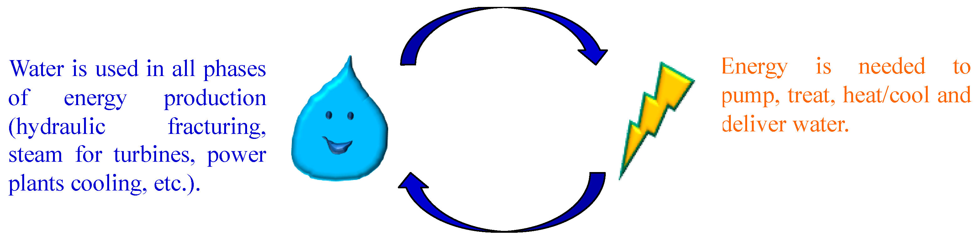
1. Introduction
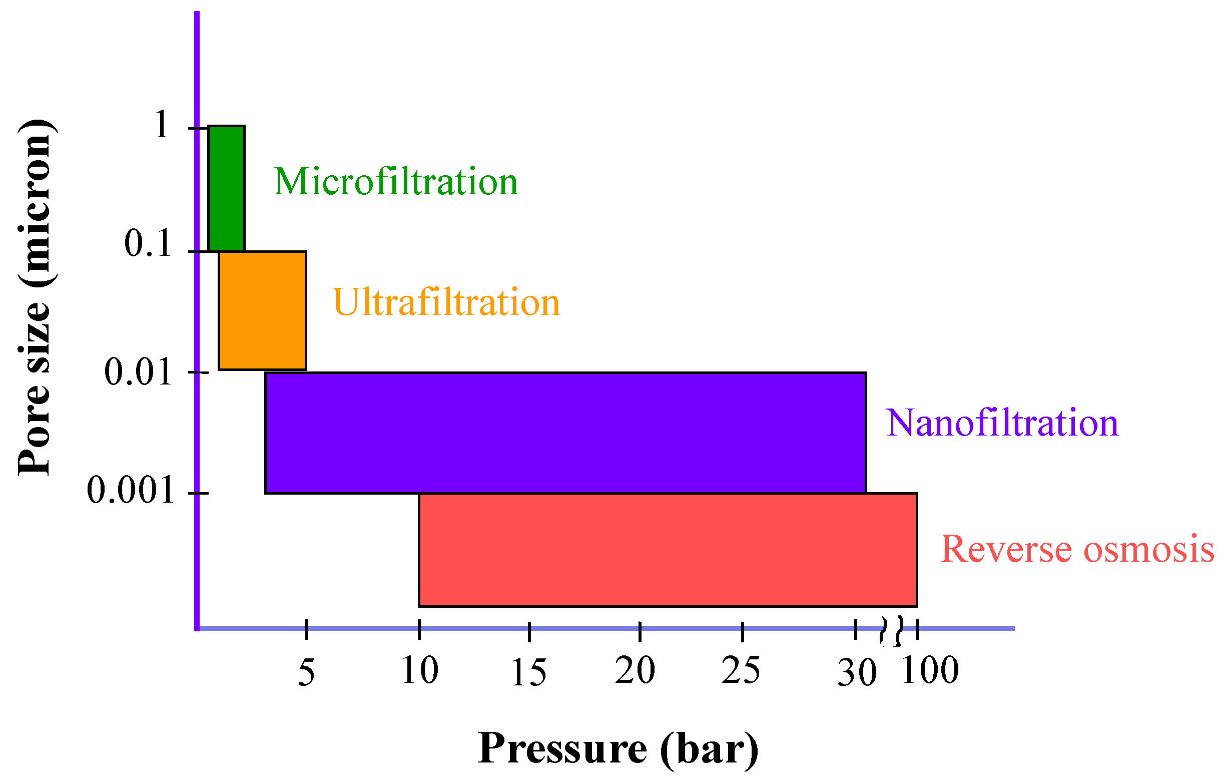
2. Membrane Operations for Water Treatment
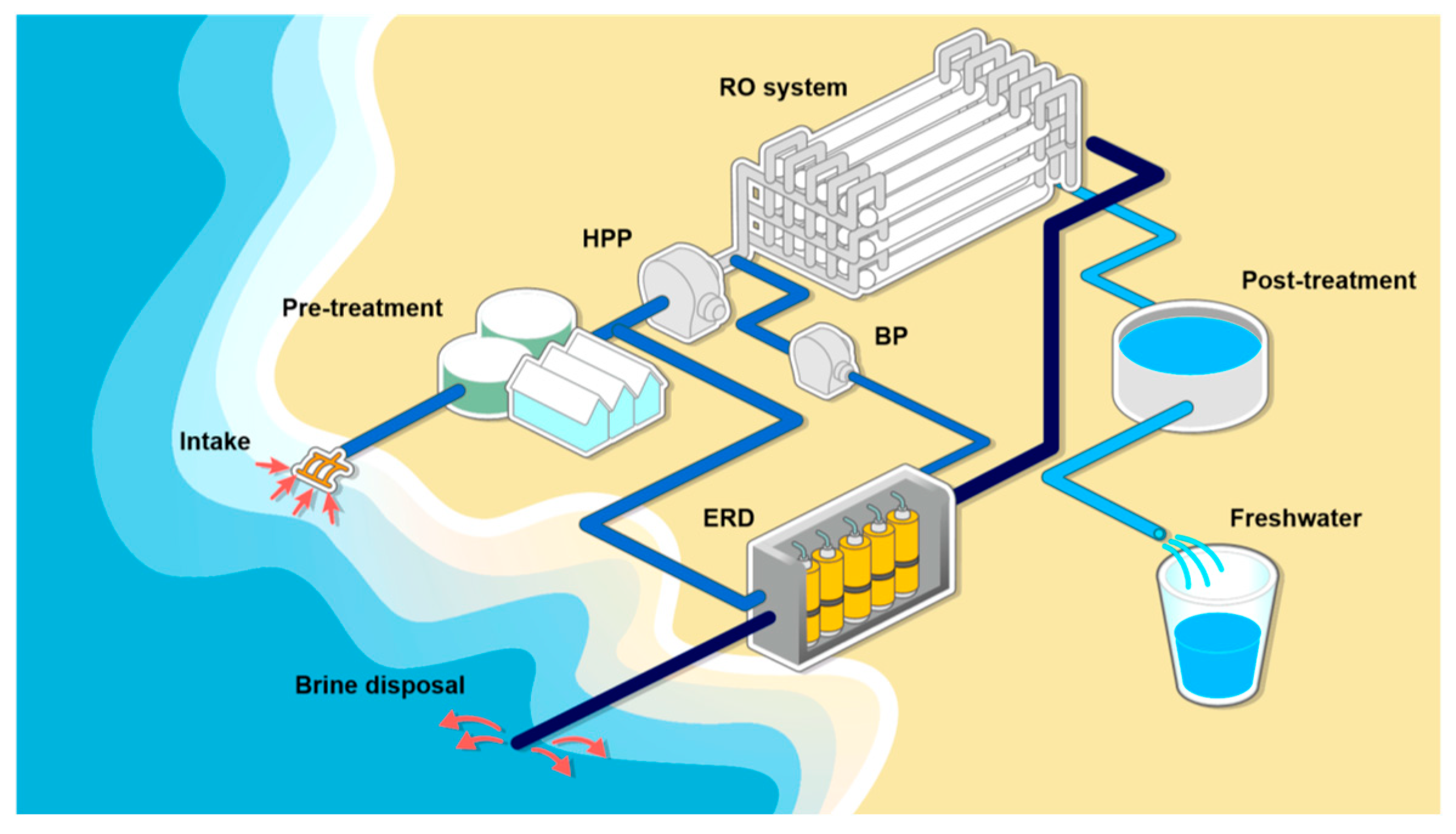
3. Case Study: Desalination by RO and MD
4. Conclusions
Funding
Institutional Review Board Statement
Informed Consent Statement
Data Availability Statement
Conflicts of Interest
References
- WCED. Our Common Future; The World Commission on Environment and Development, Oxford University Press: Oxford, UK; New York, NY, USA, 1987; p. 400. [Google Scholar]
- Available online: https://www.un.org/sustainabledevelopment/development-agenda/ (accessed on 10 February 2025).
- Sustainable Development Goals Report of the United Nations. 2023, pp. 1–80. Available online: https://unstats.un.org/sdgs/report/2023/ (accessed on 7 February 2025).
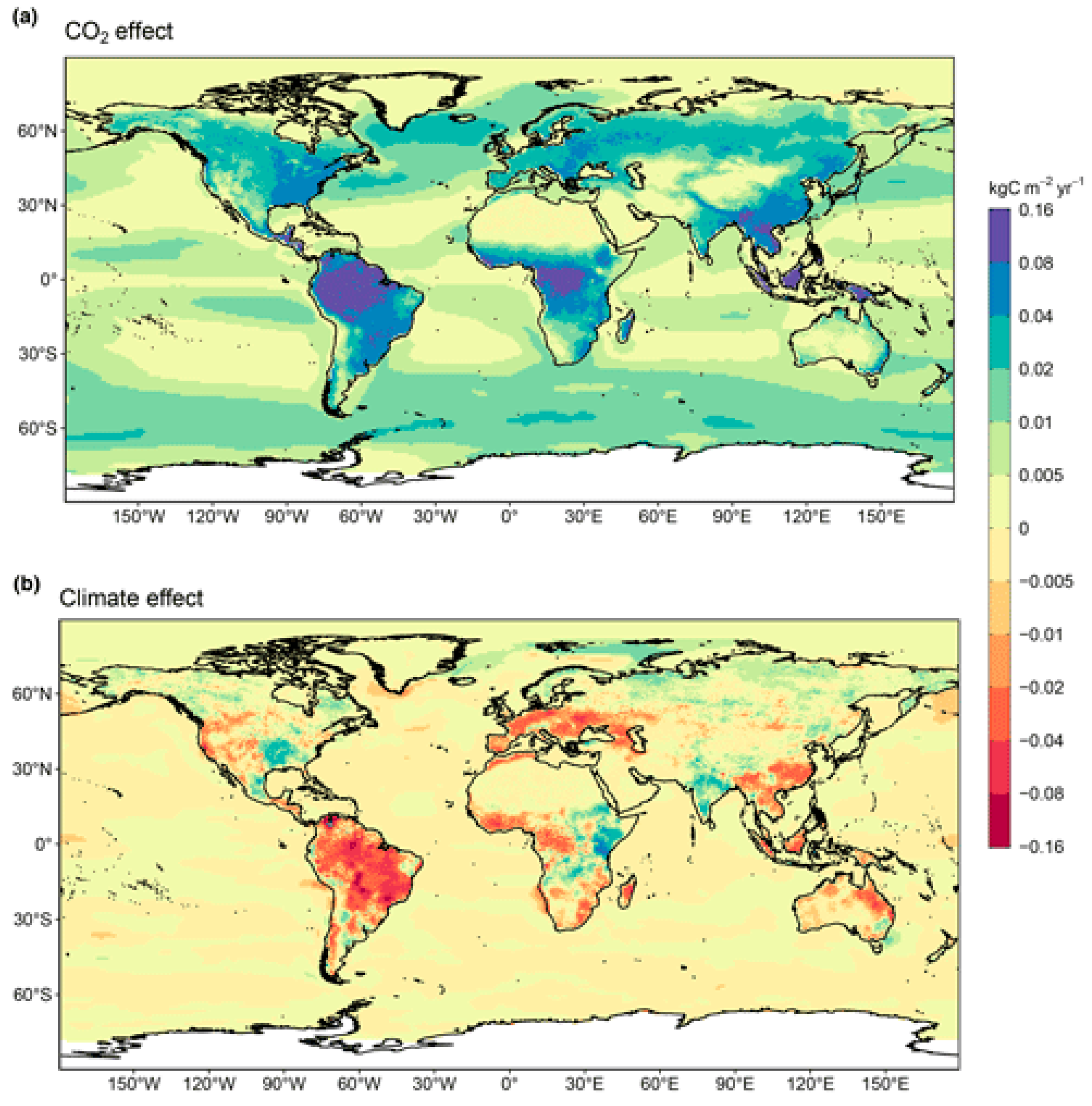
- Friedlingstein, P.; O’Sullivan, M.; Jones, M.W.; Andrew, R.M.; Bakker, D.C.E.; Hauck, J.; Landschützer, P.; Le Quéré, C.; Luijkx, I.T.; Peters, G.P.; et al. Global carbon Budget 2023. Earth Syst. Sci. Data (ESSD) 2023, 15, 5301–5369. [Google Scholar] [CrossRef]
- Badruzzaman, M.; Voutchkov, N.; Weinrich, L.; Jacangelo, J.G. Selection of pretreatment technologies for seawater reverse osmosis plants: A review. Desalination 2019, 449, 78–91. [Google Scholar] [CrossRef]
- Patel, S.K.; Lee, B.; Westerhoff, P.; Elimelech, M. The potential of electrodialysis as a cost-effective alternative to reverse osmosis for brackish water desalination. Water Res. 2024, 250, 121009. [Google Scholar] [CrossRef] [PubMed]
- Kurihara, M.; Ito, Y. Sustainable Seawater Reverse Osmosis Desalination as Green Desalination in the 21st Century. J. Membr. Sci. Res. 2020, 6, 20–29. [Google Scholar] [CrossRef]
- Kim, J.; Park, K.; Yang, D.R.; Hong, S. A comprehensive review of energy consumption of seawater reverse osmosis desalination plants. Appl. Energy 2019, 254, 113652. [Google Scholar] [CrossRef]
- Blandin, G.; Verliefde, A.R.D.; Tang, C.Y.; Le-Clech, P. Opportunities to reach economic sustainability in forward osmosis–reverse osmosis hybrids for seawater desalination. Desalination 2015, 363, 26–36. [Google Scholar] [CrossRef]
- Altaee, A.; Millar, G.J.; Zaragoza, G.; Sharif, A. Energy efficiency of RO and FO–RO system for high-salinity seawater treatment. Clean Technol. Environ. Policy 2017, 19, 77–91. [Google Scholar] [CrossRef]
- Seo, J.; Kim, Y.M.; Chae, S.H.; Lim, S.J.; Park, H.; Kim, J.H. An optimization strategy for a forward osmosis-reverse osmosis hybrid process for wastewater reuse and seawater desalination: A modeling study. Desalination 2019, 463, 40–49. [Google Scholar] [CrossRef]
- Bartholomew, T.V.; Meya, L.; Arena, J.T.; Siefert, N.S.; Mauter, M.S. Osmotically assisted reverse osmosis for high salinity brine treatment. Desalination 2017, 421, 3–11. [Google Scholar] [CrossRef]
- Peters, C.D.; Hankins, N.P. Osmotically assisted reverse osmosis (OARO): Five approaches to dewatering saline brines using pressure-driven membrane processes. Desalination 2019, 458, 1–13. [Google Scholar] [CrossRef]
- Mo, Z.; Peters, C.D.; Long, C.; Hankins, N.P.; She, Q. How split-feed osmotically assisted reverse osmosis (SF-OARO) can outperform conventional reverse osmosis (CRO) processes under constant and varying electricity tariffs. Desalination 2022, 530, 115670. [Google Scholar] [CrossRef]
- Rantissi, T.; Gitis, V.; Zong, Z.; Hankins, N. Transforming the Water-Energy Nexus in Gaza: A Systems Approach. Glob. Challenges 2024, 8, 2300304. [Google Scholar] [CrossRef]
- Zhang, H.; Yang, W.; Rainwater, K.; Song, L. Limiting extractable energy from pressure retarded osmosis with different pretreatment costs for feed and draw solutions. J. Membr. Sci. 2017, 544, 208–212. [Google Scholar] [CrossRef]
- Benjamin, J.; Arias, M.E.; Zhang, Q. A techno-economic process model for pressure retarded osmosis based energy recovery in desalination plants. Desalination 2020, 476, 114218. [Google Scholar] [CrossRef]
- Chakraborty, A.; Roy, A. Water–energy nexus for estuarine systems with seasonal salinity variations: A thermodynamic feasibility analysis of reverse osmosis (RO)–pressure retarded osmosis (PRO) combinations. Water Supply 2020, 20, 2415–2427. [Google Scholar] [CrossRef]
- Tufa, R.A.; Rugiero, E.; Chanda, D.; Hnàt, J.; van Baak, W.; Veerman, J.; Fontananova, E.; Di Profio, G.; Drioli, E.; Bouzek, K.; et al. Salinity gradient power-reverse electrodialysis and alkaline polymer electrolyte water electrolysis for hydrogen production. J. Membr. Sci. 2016, 514, 155–164. [Google Scholar] [CrossRef]
- Micari, M.; Bevacqua, M.; Cipollina, A.; Tamburini, A.; Van Baak, W.; Putts, T.; Micale, G. Effect of different aqueous solutions of pure salts and salt mixtures in reverse electrodialysis systems for closed-loop applications. J. Membr. Sci. 2018, 551, 315–325. [Google Scholar] [CrossRef]
- Ortiz-Imedio, R.; Gomez-Coma, L.; Fallanza, M.; Ortiz, A.; Ibañez, R.; Ortiz, I. Comparative performance of Salinity Gradient Power-Reverse Electrodialysis under different operating conditions. Desalination 2019, 457, 8–21. [Google Scholar] [CrossRef]
- Shalaby, S.M.; Sharshir, S.W.; Kabeel, A.E.; Kandeal, A.W.; Abosheiasha, H.F.; Abdelgaied, M.; Hamed, M.H.; Yang, N. Reverse osmosis desalination systems powered by solar energy: Preheating techniques and brine disposal challenges—A detailed review. Energy Convers. Manag. 2022, 251, 114971. [Google Scholar] [CrossRef]
- Zhang, G.; Wang, X. Seawater Desalination System Driven by Sustainable Energy: A Comprehensive Review. Energies 2024, 17, 5706. [Google Scholar] [CrossRef]
- Shokri, A.; Fard, M.S. Water-energy nexus: Cutting edge water desalination technologies and hybridized renewable-assisted systems; challenges and future roadmaps. Sustain. Energy Technol. Assess. 2023, 57, 103173. [Google Scholar] [CrossRef]
- Nassrullah, H.; Anis, S.F.; Hashaikeh, R.; Hilal, N. Energy for desalination: A state-of-the-art review. Desalination 2020, 491, 114569. [Google Scholar] [CrossRef]
- Huang, L.-B.; Di Vincenzo, M.; Li, Y.; Barboiu, M. Artificial Water Channels: Towards Biomimetic Membranes for Desalination. Chem. Eur. J. 2021, 27, 2224–2239. [Google Scholar] [CrossRef]
- Qi, S.; Wang, R.; Chaitra, G.K.M.; Torres, J.; Hu, X.; Fane, A.G. Aquaporin-based biomimetic reverse osmosis membranes: Stability and long-term performance. J. Membr. Sci. 2016, 508, 94–103. [Google Scholar] [CrossRef]
- Wan Azelee, I.; Goh, P.S.; Lau, W.J.; Ismail, A.F.; Rezaei-Dasht Arzhandi, M.; Wong, K.C.; Subramaniam, M.N. Enhanced desalination of polyamide thin film nanocomposite incorporated with acid treated multiwalled carbon nanotube-titania nanotube hybrid. Desalination 2017, 409, 163–170. [Google Scholar] [CrossRef]
- Chan, W.-F.; Marand, E.; Martin, S.M. Novel zwitterion functionalized carbon nanotube nanocomposite membranes for improved RO performance and surface anti-biofouling resistance. J. Membr. Sci. 2016, 509, 125–137. [Google Scholar] [CrossRef]
- Anis, S.F.; Hashaikeh, R.; Hilal, N. Flux and salt rejection enhancement of polyvinyl (alcohol) reverse osmosis membranes using nano-zeolite. Desalination 2019, 470, 114104. [Google Scholar] [CrossRef]
- Duan, J.; Pan, Y.; Pacheco, F.; Litwiller, E.; Lai, Z.; Pinnau, I. High-performance polyamide thin-film-nanocomposite reverse osmosis membranes containing hydrophobic zeolitic imidazolate framework-8. J. Membr. Sci. 2015, 476, 303–310. [Google Scholar] [CrossRef]
- Elsaid, K.; Kamil, M.; Sayed, E.T.; Abdelkareem, M.A.; Wilberforce, T.; Olabi, A. Environmental impact of desalination technologies: A review. Sci. Total Environ. 2020, 748, 141528. [Google Scholar] [CrossRef]
- Missimer, T.M.; Maliva, R.G. Environmental issues in seawater reverse osmosis desalination: Intakes and outfalls. Desalination 2018, 434, 198–215. [Google Scholar] [CrossRef]
- Panagopoulos, A.; Haralambous, K.-J. Environmental impacts of desalination and brine treatment-Challenges and mitigation measures. Mar. Pollut. Bull. Part B 2020, 161, 111773. [Google Scholar] [CrossRef]
- Winter, D.; Koschikowski, J.; Wieghaus, M. Desalination using membrane distillation: Experimental studies on fullscale spiral wound modules. J. Membr. Sci. 2011, 375, 104–112. [Google Scholar] [CrossRef]
- Jansen, A.E.; Assink, J.W.; Hanemaaijer, J.H.; van Medevoort, J.; van Sonsbeek, E. Development and pilot testing offull-scale membrane distillation modules for deployment of waste heat. Desalination 2013, 323, 55–65. [Google Scholar] [CrossRef]
- Available online: www.memsys.eu (accessed on 10 February 2025).
- Zhao, K.; Heinzl, W.; Wenzel, M.; Büttner, S.; Bollen, F.; Lange, G.; Heinzl, S.; Sarda, N. Experimental study of the memsys vacuum-multi-effect-membrane-distillation (V-MEMD) module. Desalination 2013, 323, 150–160. [Google Scholar] [CrossRef]
- Kim, Y.-D.; Thu, K.; Choi, S.-H. Solar-assisted multi-stage vacuum membrane distillation system with heat recovery unit. Desalination 2015, 367, 161–171. [Google Scholar] [CrossRef]
- Gopi, G.; Arthanareeswaran, G.; Ismail, A.F. Perspective of renewable desalination by using membrane distillation. Chem. Eng. Res. Des. 2019, 144, 520–537. [Google Scholar] [CrossRef]
- Li, Q.; Beier, L.-J.; Tan, J.; Brown, C.; Lian, B.; Zhong, W.; Wang, Y.; Ji, C.; Dai, P.; Li, T.; et al. An integrated, solar-driven membrane distillation system for water purification and energy generation. Appl. Energy 2019, 237, 534–548. [Google Scholar] [CrossRef]
- Anand, B.; Shankar, R.; Murugavelh, S.; Rivera, W.; Prasad, K.M.; Nagarajan, R. A review on solar photovoltaic thermal integrated desalination technologies. Renew. Sustain. Energy Rev. 2021, 141, 110787. [Google Scholar] [CrossRef]
- Shalaby, S.M.; Hammad, F.A.; Zayed, M.E. Current progress in integrated solar desalination systems: Prospects from coupling configurations to energy conversion and desalination processes. Process. Saf. Environ. Prot. 2023, 178, 494–510. [Google Scholar] [CrossRef]
- Sarbatly, R.; Chiam, C.-K. Evaluation of geothermal energy in desalination by vacuum membrane distillation. Appl. Energy 2013, 112, 737–746. [Google Scholar] [CrossRef]
- Khan, E.U.; Martin, A.R. Optimization of hybrid renewable energy polygeneration system with membrane distillation for rural households in Bangladesh. Energy 2015, 93, 1116–1127. [Google Scholar] [CrossRef]
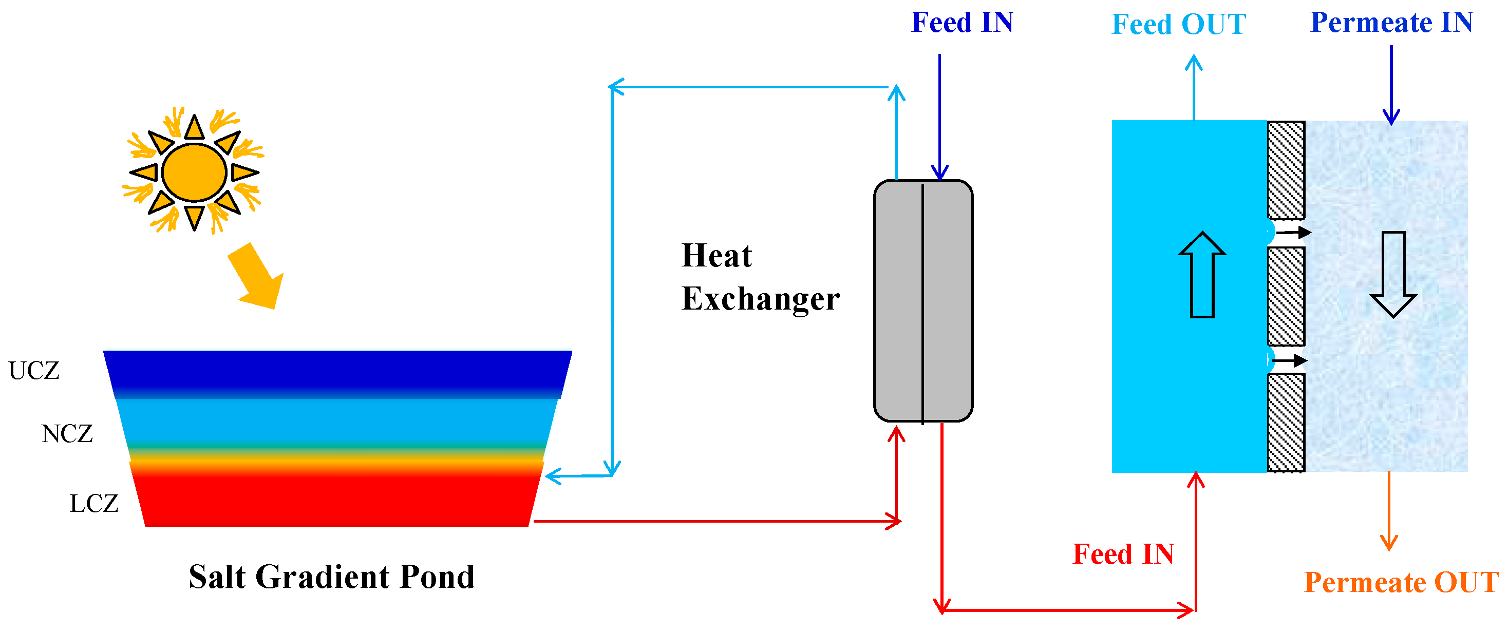
- Nakoa, K.; Rahaoui, K.; Date, A.; Akbarzadeh, A. An experimental review on coupling of solar pond with membrane distillation. Sol. Energy 2015, 119, 319–331. [Google Scholar] [CrossRef]
- Suárez, F.; Urtubia, R. Tackling the water-energy nexus: An assessment of membrane distillation driven by salt-gradient solar ponds. Clean Technol. Environ. Policy 2016, 18, 1697–1712. [Google Scholar] [CrossRef]
- Zaragoza, G.; Ruiz-Aguirre, A.; Guillén-Burrieza, E. Efficiency in the use of solar thermal energy of small membrane desalination systems for decentralized water production. Appl. Energy 2014, 130, 491–499. [Google Scholar] [CrossRef]
- Chafidz, A.; Kerme, E.D.; Wazeer, I.; Khalid, Y.; Ajbar, A.; Al-Zahrani, S.M. Design and fabrication of a portable and hybrid solar-powered membrane distillation system. J. Clean. Prod. 2016, 133, 631–647. [Google Scholar] [CrossRef]
- Raluy, R.G.; Schwantes, R.; Subiela, V.J.; Peñate, B.; Melián, G.; Betancort, J.R. Operational experience of a solar membrane distillation demonstration plant in Pozo Izquierdo-Gran Canaria Island (Spain). Desalination 2012, 290, 1–13. [Google Scholar] [CrossRef]
- Lee, J.-G.; Kim, W.-S.; Choi, J.-S.; Ghaffour, N.; Kim, Y.-D. Dynamic solar-powered multi-stage direct contact membrane distillation system: Concept design, modeling and simulation. Desalination 2018, 435, 278–292. [Google Scholar] [CrossRef]
- Wang, Y.; Xu, Z.; Lior, N.; Zeng, H. An experimental study of solar thermal vacuum membrane distillation desalination. Desalin. Water Treat. 2015, 53, 887–897. [Google Scholar] [CrossRef]
- Mohan, G.; Kumar, U.; Pokhrel, M.K.; Martin, A. A novel solar thermal polygeneration system for sustainable production of cooling, clean water and domestic hot water in United Arab Emirates: Dynamic simulation and economic evaluation. Appl. Energy 2016, 167, 173–188. [Google Scholar] [CrossRef]
- Qtaishat, M.R.; Banat, F. Desalination by solar powered membrane distillation systems. Desalination 2013, 308, 186–197. [Google Scholar] [CrossRef]
- Moore, S.E.; Mirchandani, S.D.; Karanikola, V.; Nenoff, T.M.; Arnold, R.G.; Sáez, A.E. Process modeling for economic optimization of a solar driven sweeping gas membrane distillation desalination system. Desalination 2018, 437, 108–120. [Google Scholar] [CrossRef]
- Cheng, L.H.; Lin, Y.H.; Chen, J. Enhanced air gap membrane desalination by novel finned tubular membrane modules. J. Membr. Sci. 2011, 378, 398–406. [Google Scholar] [CrossRef]
- Summers, E.K.; Lienhard, J.H. Experimental study of thermal performance in air gap membrane distillation systems, including the direct solar heating of membranes. Desalination 2013, 330, 100–111. [Google Scholar] [CrossRef]
- Ho, C.-D.; Ng, C.A.; Wang, P.-H.; Cheng, C.-H. Theoretical and experimental studies of immediate assisted solar air gap membrane distillation systems. Desalination Water Treat. 2016, 57, 3846–3860. [Google Scholar] [CrossRef]
- Guillén-Burrieza, E.; Blanco, J.; Zaragoza, G.; Alarcón, D.-C.; Palenzuela, P.; Ibarra, M.; Gernjak, W. Experimental analysis of an air gap membrane distillation solar desalination pilot system. J. Membr. Sci. 2011, 379, 386–396. [Google Scholar] [CrossRef]
- Guillén-Burrieza, E.; Zaragoza, G.; Miralles-Cuevas, S.; Blanco, J. Experimental evaluation of two pilot-scale membrane distillation modules used for solar desalination. J. Membr. Sci. 2012, 409–410, 264–275. [Google Scholar] [CrossRef]
- Walton, J.; Lu, H.; Turner, C.; Solis, S.; Hein, H. Solar and Waste Heat Desalination by Membrane Distillation. In Desalination and Water Purification Research and Development Program Report No. 81; College of Engineering, University of Texas at El Paso: El Paso, TX, USA, 2004. [Google Scholar]
- Mericq, J.-P.; Laborie, S.; Cabassud, C. Evaluation of systems coupling vacuum membrane distillation and solar energy for seawater desalination. Chem. Eng. J. 2011, 166, 596–606. [Google Scholar] [CrossRef]
- Zhao, R.; Li, J.; Zhang, Z.; Long, R.; Liu, W.; Liu, Z. Harvesting net power and desalinating water by pressure-retarded membrane distillation. Sci. China Technol. Sci. 2022, 65, 214–220. [Google Scholar] [CrossRef]
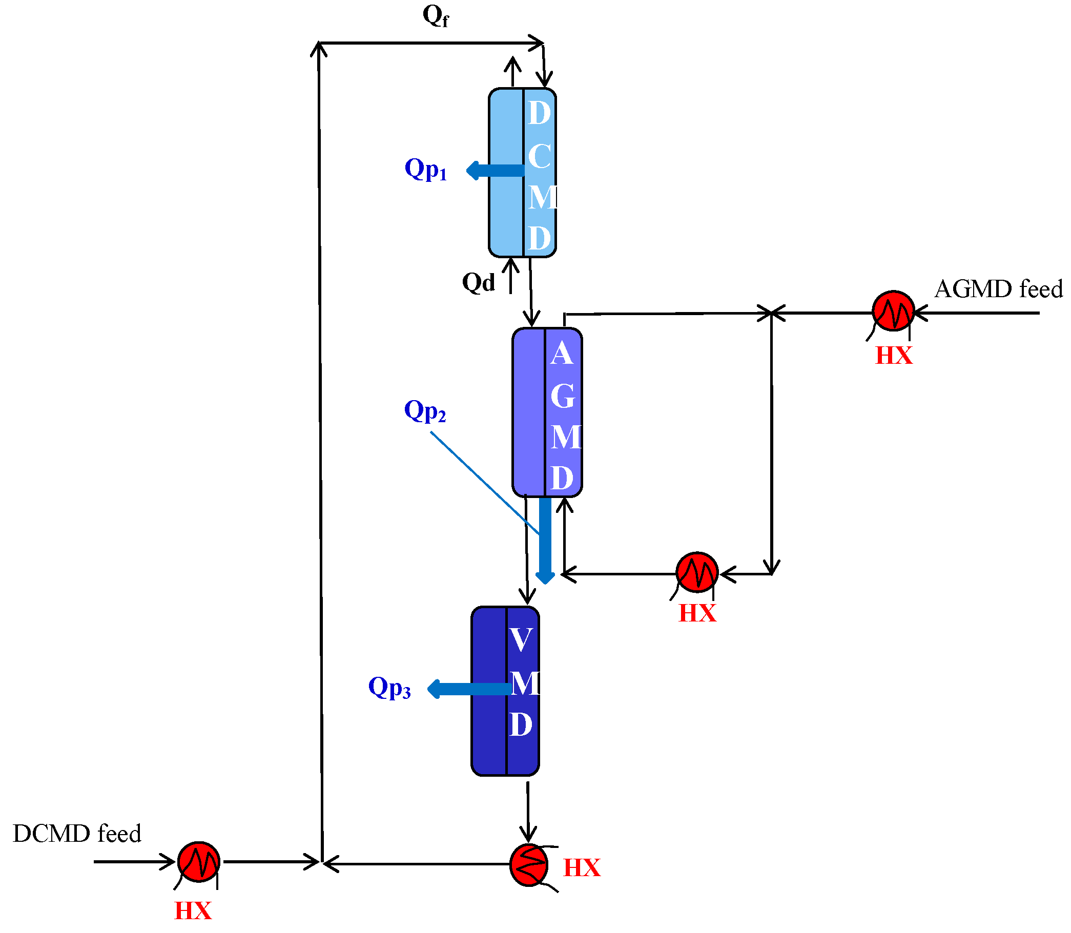
- Criscuoli, A. Improvement of the Membrane Distillation performance through the integration of different configurations. Chem. Eng. Res. Des. 2016, 111, 316–322. [Google Scholar] [CrossRef]
- Criscuoli, A. Thermal Performance of Integrated Direct Contact and Vacuum Membrane Distillation Units. Energies 2021, 14, 7405. [Google Scholar] [CrossRef]
- Criscuoli, A. Boosting the Membrane Distillation performance by exploiting its configurations. Sep. Purif. Technol. 2025, 361, 131510. [Google Scholar] [CrossRef]
- Criscuoli, A.; Drioli, E. New metrics for evaluating the performance of membrane operations in the logic of process intensification. Ind. Eng. Chem. Res. 2007, 46, 2268–2271. [Google Scholar] [CrossRef]
- Taamneh, Y.; Bataineh, K. Improving the performance of direct contact membrane distillation utilizing spacer-filled channel. Desalination 2017, 408, 25–35. [Google Scholar] [CrossRef]
- Kandi, A.; Mohammed, H.A.; Khiadani, M.; Shafieian, A. The effect of turbulence promoters on DCMD process: A comprehensive review. J. Water Process. Eng. 2025, 69, 106810. [Google Scholar] [CrossRef]
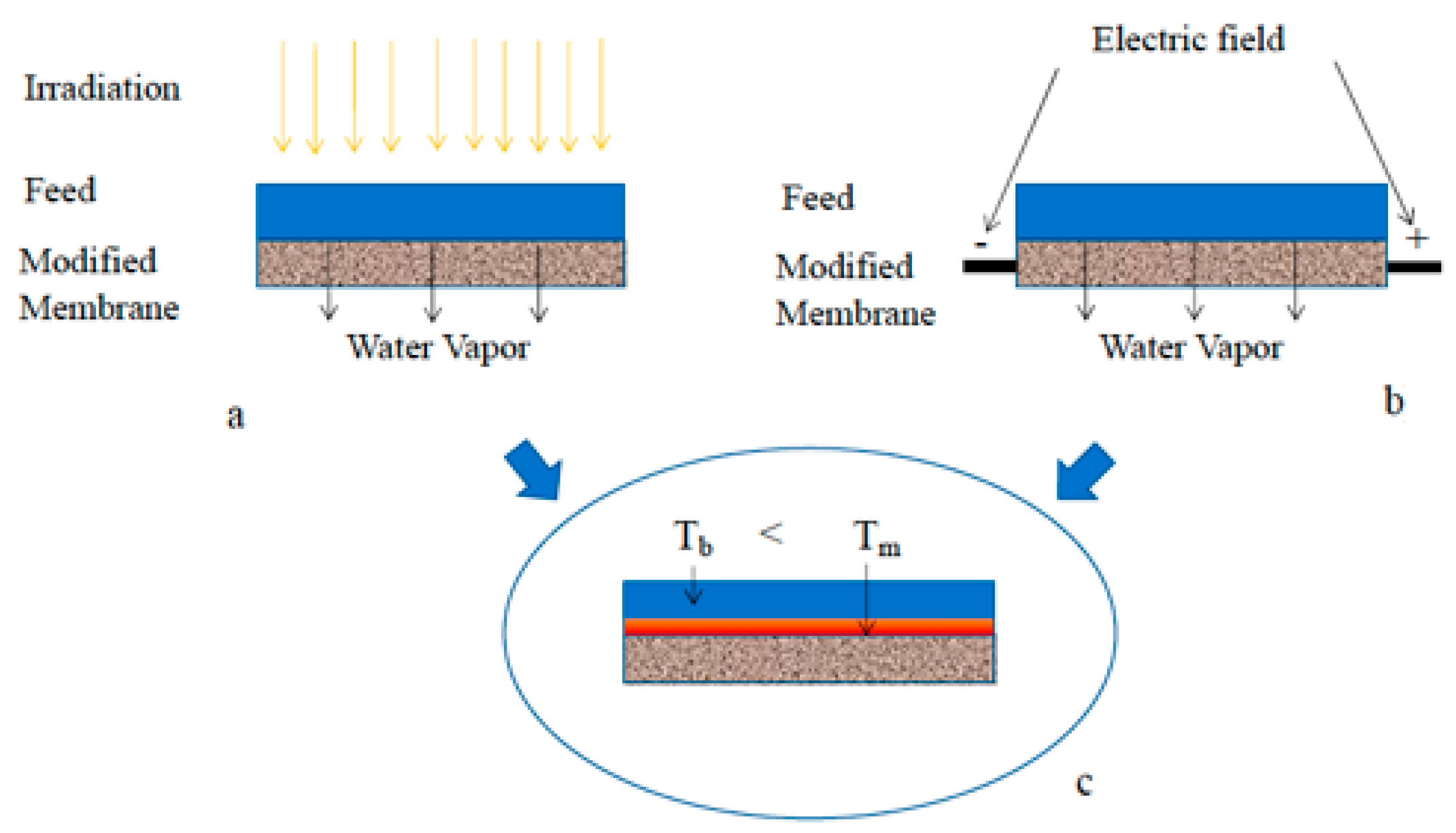
- Ye, H.; Li, X.; Deng, L.; Li, P.; Zhang, T.; Wang, X.; Hsiao, B.S. Silver nanoparticle-enabled photothermal nanofibrous membrane for light-driven membrane distillation. Ind. Eng. Chem. Res. 2019, 58, 3269–3281. [Google Scholar] [CrossRef]
- Song, L.; Huang, Q.; Huang, Y.; Bi, R.; Xiao, C. An electro-thermal braid-rein- forced PVDF hollow fiber membrane for vacuum membrane distillation. J. Membr. Sci. 2019, 591, 117359. [Google Scholar] [CrossRef]
- Anvari, A.; Kekre, K.M.; Azimi, Y.A.; Yao, Y.; Ronen, A. Membrane distillation of high salinity water by induction heated thermally conducting membranes. J. Membr. Sci. 2019, 589, 117253. [Google Scholar] [CrossRef]
- Subrahmanya, T.M.; Lin, P.T.; Chiao, Y.-H.; Widakdo, J.; Chuang, C.-H.; Rahmadhanty, S.F.; Yoshikawa, S.; Hung, W.-S. High Performance Self-Heated Membrane Distillation System for Energy Efficient Desalination Process. J. Mater. Chem. A 2021, 9, 7868–7880. [Google Scholar] [CrossRef]
- Huang, J.; Tang, T.; He, Y. Coupling photothermal and Joule-heating conversion for self-heating membrane distillation enhancement. Appl. Therm. Eng. 2021, 199, 117557. [Google Scholar] [CrossRef]
- Soukane, S.; Son, H.S.; Mustakeem, M.; Obaid, M.; Alpatova, A.; Qamar, A.; Jin, Y.; Ghaffour, N. Materials for energy conversion in membrane distillation localized heating: Review, analysis and future perspectives of a paradigm shift. Renew. Sustain. Energy Rev. 2022, 167, 112702. [Google Scholar] [CrossRef]
- Farid, M.U.; Kharraz, J.A.; Sun, J.; Boey, M.W.; Riaz, M.A.; Wong, P.W.; Jia, M.; Zhang, X.; Deka, B.J.; Khanzada, N.K.; et al. Advancements in Nanoenabled Membrane Distillation for a Sustainable Water-Energy-Environment Nexus. Adv. Mater. 2023, 36, 2307950. [Google Scholar] [CrossRef]
- Criscuoli, A.; Carnevale, M.C. Localized heating to improve the thermal efficiency of membrane distillation systems. Energies 2022, 15, 5990. [Google Scholar] [CrossRef]
- Zhang, Y.; Liu, L.; Li, K.; Hou, D.; Wang, J. Enhancement of Energy Utilization Using Nanofluid in Solar Powered Membrane Distillation. Chemosphere 2018, 212, 554–562. [Google Scholar] [CrossRef] [PubMed]
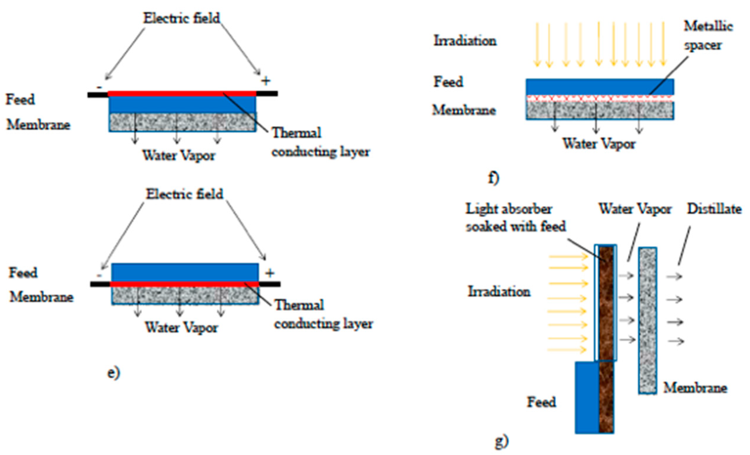
- Ang, E.H.; Tan, Y.Z.; Chew, J.W. A three-dimensional plasmonic spacer enables highly efficient solar-enhanced membrane distillation of seawater. J. Mater. Chem. A 2019, 7, 10206. [Google Scholar] [CrossRef]
- Tan, Y.Z.; Ang, E.H.; Chew, J.W. Metallic spacers to enhance membrane distillation. J. Membr. Sci. 2019, 572, 171–183. [Google Scholar] [CrossRef]
- Han, F.; Liu, S.; Wang, K.; Zhang, X. Enhanced Performance of Membrane Distillation Using Surface Heating Process. Membranes 2021, 11, 866. [Google Scholar] [CrossRef]
- Wang, J.; Liu, Y.; Rao, U.; Dudley, M.; Ebrahimi, N.D.; Lou, J.; Han, F.; Hoek, E.M.V.; Tilton, N.; Cath, T.Y.; et al. Conducting thermal energy to the membrane/water interface for the enhanced desalination of hypersaline brines using membrane distillation. J. Membr. Sci. 2021, 626, 119188. [Google Scholar] [CrossRef]
- Gong, B.; Yang, H.; Wu, S.; Xiong, G.; Yan, J.; Cen, K.; Bo, Z.; Ostrikov, K. Graphene Array-Based Anti-fouling Solar Vapour Gap Membrane Distillation with High Energy Efficiency. Nano-Micro Lett. 2019, 11, 51. [Google Scholar] [CrossRef]


| Desalination Process | SEC (kWh/m3) | Normalized (to SWRO) Capital Cost |
|---|---|---|
| SWRO | 2.5–4.0 | 1.00 |
| FO-RO | 1.3–1.5 | 1.21 |
| OARO | 1.8 | 1.15 |
Disclaimer/Publisher’s Note: The statements, opinions and data contained in all publications are solely those of the individual author(s) and contributor(s) and not of MDPI and/or the editor(s). MDPI and/or the editor(s) disclaim responsibility for any injury to people or property resulting from any ideas, methods, instructions or products referred to in the content. |
© 2025 by the author. Licensee MDPI, Basel, Switzerland. This article is an open access article distributed under the terms and conditions of the Creative Commons Attribution (CC BY) license (https://creativecommons.org/licenses/by/4.0/).
Share and Cite
Criscuoli, A. Water–Energy Nexus: Membrane Engineering Towards a Sustainable Development. Membranes 2025, 15, 98. https://doi.org/10.3390/membranes15040098
Criscuoli A. Water–Energy Nexus: Membrane Engineering Towards a Sustainable Development. Membranes. 2025; 15(4):98. https://doi.org/10.3390/membranes15040098
Chicago/Turabian StyleCriscuoli, Alessandra. 2025. "Water–Energy Nexus: Membrane Engineering Towards a Sustainable Development" Membranes 15, no. 4: 98. https://doi.org/10.3390/membranes15040098
APA StyleCriscuoli, A. (2025). Water–Energy Nexus: Membrane Engineering Towards a Sustainable Development. Membranes, 15(4), 98. https://doi.org/10.3390/membranes15040098