1. Introduction
Biotechnology manufacturing processes make use of cell culture operations to grow cells that produce the desired therapeutic (e.g., monoclonal antibodies, virus vectors, etc.). Bioreactor clarification operations are used to remove the unwanted particulate matter (cells, cell debris, etc.) from the growth medium that contains the product of interest. Typically, manufacturing processes are run in batch mode.
However, there is significant interest in the development of continuous biomanufacturing processes [
1]. The major advantages of continuous manufacturing processes are lower capital and operating costs. This results from the more efficient utilization of the process equipment, a smaller footprint and equipment size, and a higher productivity due to less equipment downtime [
2]. However, in the biopharmaceutical industry, the cost of goods has not been the dominant driver, explaining the slower development of continuous biomanufacturing processes. This has begun to change with the development of biosimilars and the desire to enable greater US-based manufacturing to reduce the reliance on overseas supply chains. Additionally, continuous biomanufacturing can lead to improved product quality resulting from the much shorter residence times and steady state operation.
Most of the advances in continuous biomanufacturing have focused on upstream processes [
3]. Significant progress has been made on the development of continuous cell culture processes, with media added continuously while the product is removed in what is commonly referred to as a perfusion bioreactor. Cost analyses indicate that higher cell densities obtained in continuous cell culture operations lead to higher production rates and lower costs [
4]. Unlike batch operations, where the bioreactor is clarified at the end of the cell culture operation, the product needs to be removed continuously while retaining the cells in perfusion operations. Consequently, some type of cell retention device must be integrated with the bioreactor. A variety of cell retention devices have been explored with different methods of action, such as filtration, sedimentation, centrifugation, ultrasonic fixation, and dielectrophoretic exclusion [
5]. Filtration-based methods are of particular interest since they can effectively remove both whole cells and relatively small cell debris, depending upon the pore size of the filter. Here, we focused on tangential flow filtration (TFF), as it can easily be incorporated into batch and continuous manufacturing processes.
TFF has many advantages over other bioreactor clarification operations for both batch and continuous processing [
6]. If an appropriate-pore-size membrane is used, e.g., 0.22 or 0.45 mm, the permeate is sufficiently “clean” to be directly fed to the subsequent capture step (most commonly Protein A chromatography for monoclonal antibody production). However, the high cell density in state-of-the-art bioreactors often causes membrane fouling, leading to product rejection and a low filtrate flux, compromising the viability of TFF. Further, especially for emerging therapeutics such as virus vectors, cell lysis is often required, as the product of interest is not excreted into the growth medium. TFF for the clarification of cell lysates is extremely challenging due to rapid membrane fouling.
TFF can easily be incorporated as a cell retention device in perfusion operations. However, high cell densities tend to lead to higher rates of fouling. Higher rates of fouling invariably lead to product sieving losses during operation, especially over extended periods of time. Three methods may be used to minimize fouling during TFF. The membrane structure can be modified. Da et al. [
7,
8] indicated that the use of a reverse asymmetric membrane where the more open pore structure faces the feed stream and the barrier layer faces the permeate can lead to higher productivity during batch operation. Alternatively, one can modify the TFF operating conditions. For example, alternating tangential filtration (ATF), in which the direction of the feed flow is alternated in a cyclic fashion, can minimize fouling, but the operating filtrate flux in these systems is typically <3 L m
−2 h
−1 [
9]; thus, large membrane areas are required for commercial manufacturing operations.
A third approach for enhancing the performance of TFF that is appropriate for both batch and continuous operations is to integrate TFF as a secondary clarification step with another unit operation used to reduce the load of particulate matter (cells and cell debris) before performing TFF. In perfusion processes, the primary clarification operation must be amenable for continuous operation with the recycling of the retained cells. Thus, depth filtration, which is widely used for initial clarification, is not viable in this application. The incorporation of an appropriate continuous primary clarification step would reduce the particulate load in the feed to the TFF step, minimizing fouling and the associated reductions in product recovery during extended operation of the perfusion bioreactor. Modular chemical process intensification, where two unit operations are combined to achieve an integrated system with a higher performance than each of the individual unit operations, is of growing interest in the biotechnology industry [
10,
11]. Here, we investigated for the first time the use of a hydrocyclone as the primary clarification operation in combination with TFF as the secondary clarification operation.
Hydrocyclones have been used for many years for particle separations from liquid streams in the mineral-processing, chemical, and petrochemical industries. They can be easily scaled up and used in continuous manufacturing and have low operating costs [
12,
13]. The feed stream is introduced at the top of the hydrocyclone, as shown in
Figure 1a. There are two exits from the hydrocyclone: the underflow, which contains the larger (higher-density) particulate matter, and the overflow, which contains a low concentration of smaller (lower-density) particles. The larger and higher-density particles move towards the wall due to centrifugal and drag forces as well as the pressure gradient. They then move downwards and into the underflow. The smaller and lower-density particles move upwards and exit with the overflow [
14]. The degree of separation of the particles into the underflow depends on the rate of centrifugal sedimentation. While the principle of separation is the same as in classical centrifugation, the hydrocyclone has no moving parts, eliminating many of the challenges of large-scale continuous centrifuges.
Several investigators have examined the use of a hydrocyclone alone for mammalian cell separations [
15,
16]. These studies indicate that, for CHO cells, a separation efficiency in the overflow versus underflow as high as 99% can be obtained with cell viabilities as high as 90% at pressure drops of up to 3 bar. Hydrocyclones have also been used as a cell retention device for perfusion bioreactors where similar cell viabilities were achieved. Ni et al. [
13] provided a review of the important design parameters.
Hydrocyclones are ideally suited for the separation of particles 10 mm or larger, but they are much less effective at removing smaller cell debris. Particles of a given size will reach an equilibrium radial position where the outward terminal settling velocity equals the inward radial velocity of the liquid (see
Figure 1a). Particles with an equilibrium position that coincides with the locus of zero liquid vertical velocity have an equal probability of leaving via the underflow or overflow. This is known as the cut size. Reducing the cut size by optimizing the various geometric parameters will lead to higher feed pressures. However, high feed pressures are undesirable for perfusion bioreactors, as they will adversely affect cell viability. Thus, a secondary clarification operation will be required after the hydrocyclone to obtain a product stream suitable for subsequent downstream processing operations.
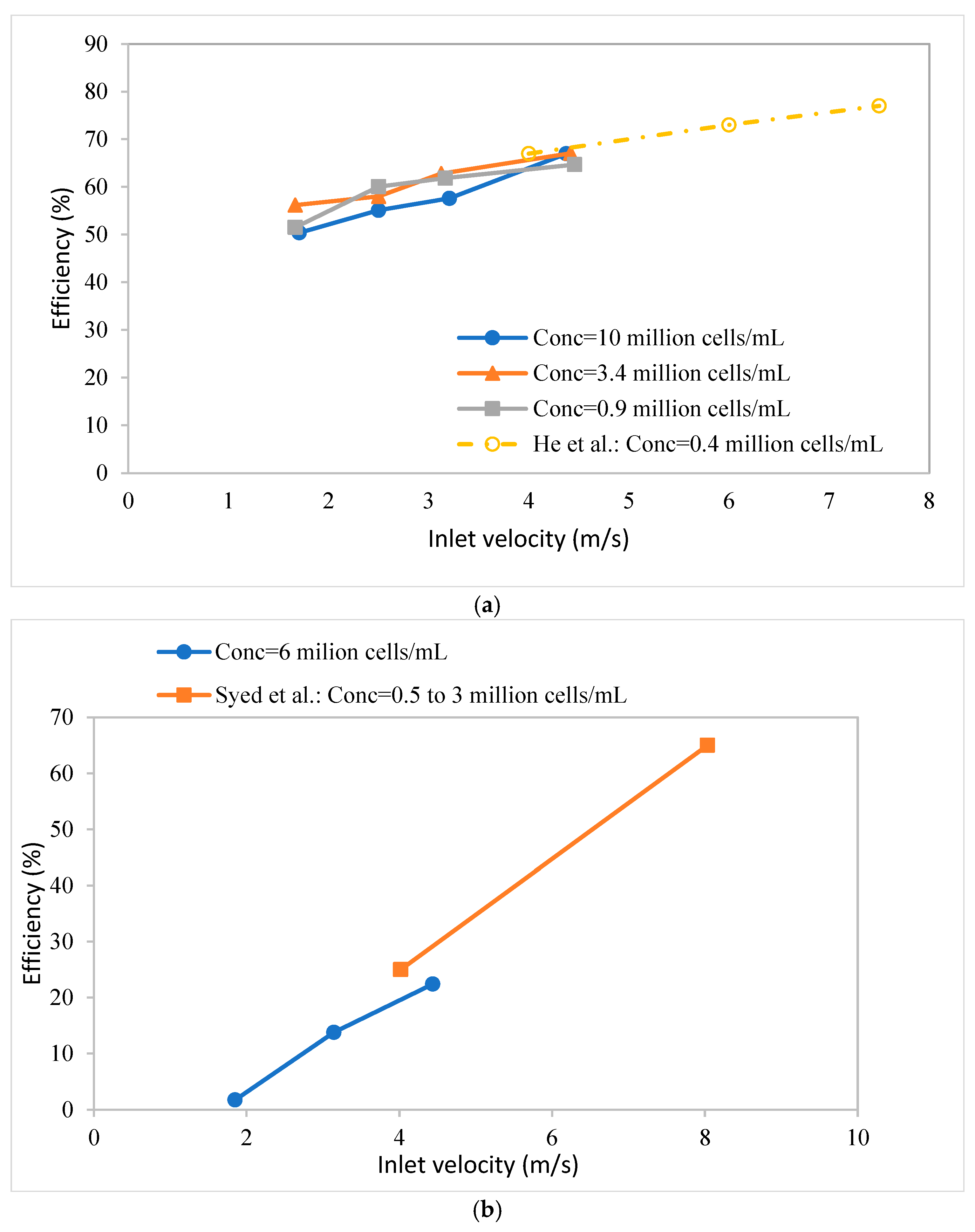
Syed et al. [
17] used a hydrocyclone for primary cell separation, with a spiral microchannel used for secondary clarification, as the cell retention device for a perfusion bioreactor. They indicated up to 75% separation of cells by the hydrocyclone with <5% loss in cell viability. The spiral microchannel system removed more than 90% of the remaining particulate matter; thus, some type of additional clarification would likely still be needed. In addition, scaling up the spiral microchannel device is likely to be challenging. He et al. [
18] investigated in detail the viability loss of CHO cells for a continuous cell culture using hydrocyclones. They indicate that cell viability decreases with an increase in the hydrocyclone cone angle (see
Figure 1b) and inlet velocity due to the increased pressure drop to which the cells are subjected. The highest separation efficiencies obtained by He et al. [
18] were <90%, although there was no discussion of how the required secondary clarification would be performed.
The current study provides the first analysis of using a hydrocyclone in combination with TFF in order to improve the performance of the TFF operation. The hydrocyclone reduces the load of particulate matter in the feed stream to the microfiltration unit, significantly reducing the rate of fouling and increasing the performance of the TFF unit. Two different hydrocyclones were fabricated using 3D printing based on literature designs. Two different TFF modules were investigated, with one containing an essentially symmetric membrane and one having a reverse asymmetric membrane. The effects of the different membrane morphologies are also discussed. The results provide insights into the development of an integrated hydrocyclone–TFF bioreactor clarification process with applications in batch and continuous bioprocessing operations.
2. Materials and Methods
2.1. Materials
The reagents used in this study were biotechnology grade or higher if not specified. FreeStyle™ CHO-S cells were obtained from ThermoFisher (Waltham, MA, USA). CHOgro® Expression Media and the poloxamer 188 (Pluronic) solution, 10% w/v in cell-culture-grade water, were purchased from Mirus Bio (Madison, WI, USA). L-glutamine, TRITON™ X-100, and sodium hydroxide were purchased from VWR (Radnor, PA, USA). Trypan blue was purchased from Sigma-Aldrich (Burlington, MA, USA).
All the rubber tubing and peristaltic pumps used to deliver fluids were purchased from Masterflex (Vernon Hills, IL, USA). The water used in this work was obtained from a ThermoFisher 18 MΩ Barnstead Smart2pure system (Schwerte, Germany). An electronic scale (PL602-S) was purchased from Mettler Toledo (Columbus, OH, USA). Two hollow fiber microfiltration modules were custom manufactured for this work by Asahi Kasei Bioprocess (Glenview, Il, USA). The BioOptimal™ MF-SL filter had a membrane surface area of 0.00041 m2, with a pore size of 0.4 μm on the permeate side and 40 μm on the feed side. The module is unique in that the more open support structure faces the feed, unlike conventional microfiltration modules in which the size-selective “skin” faces the feed. The UJP module has a membrane surface area of 0.00032 m2. The barrier layer, which faces the feed stream, has a nominal pore size of 0.65 μm, as provided by the manufacturer. While there is variation in the average pore size from the inside to the outside of the fiber, the membrane is much more symmetric in structure. Both hollow fiber membranes were manufactured by a wet spinning process. The membrane materials were polyvinylidene-fluoride for the UJP and polysulfone for the BioOptimal MF-SL filters. The hydrocyclones were fabricated by 3D printing as described below.
2.2. Cell Culture
FreeStyle™ CHO-S cells were cultured using flasks in a shaker incubator at 37 °C and 125 rpm. A humidified atmosphere consisting of 8% CO2 was used. Cell titers of up to 25 million cells/mL were obtained using CHOgro® Expression media supplemented with 8 mM L-glutamine and 0.3% pluronic. First, CHO cells were thawed and then passaged after a few days repeatedly to obtain the desired concentration. The cell density was evaluated under a microscope using a hemacytometer with trypan blue exclusion dye used to identify the number of dead cells. The trypan blue exclusion assay is based on the principle that live cells have intact cell membranes that will exclude the dye, while dead cells will turn blue. The cell sample was mixed with dye and then visually examined. Viable cells appeared clear while nonviable cells appeared blue.
The cell viability was determined by Equation (1):
where
and
are the number of viable and total cells, respectively.
2.3. Hydrocyclone Designs
There have been numerous studies that have considered the design of hydrocyclones [
19]. Several geometrical and operational factors should be considered, among which the inlet and outlet diameters, cone angle, vortex finder depth and thickness, inlet pressure and velocity, and concentration of particulate matter are important [
12,
13]. The inlet and outlet diameters and ratios primarily influence the velocity of the fluid and the pressure drop. For mammalian cells, these two factors are important, as high pressures lead to a reduction in cell viability.
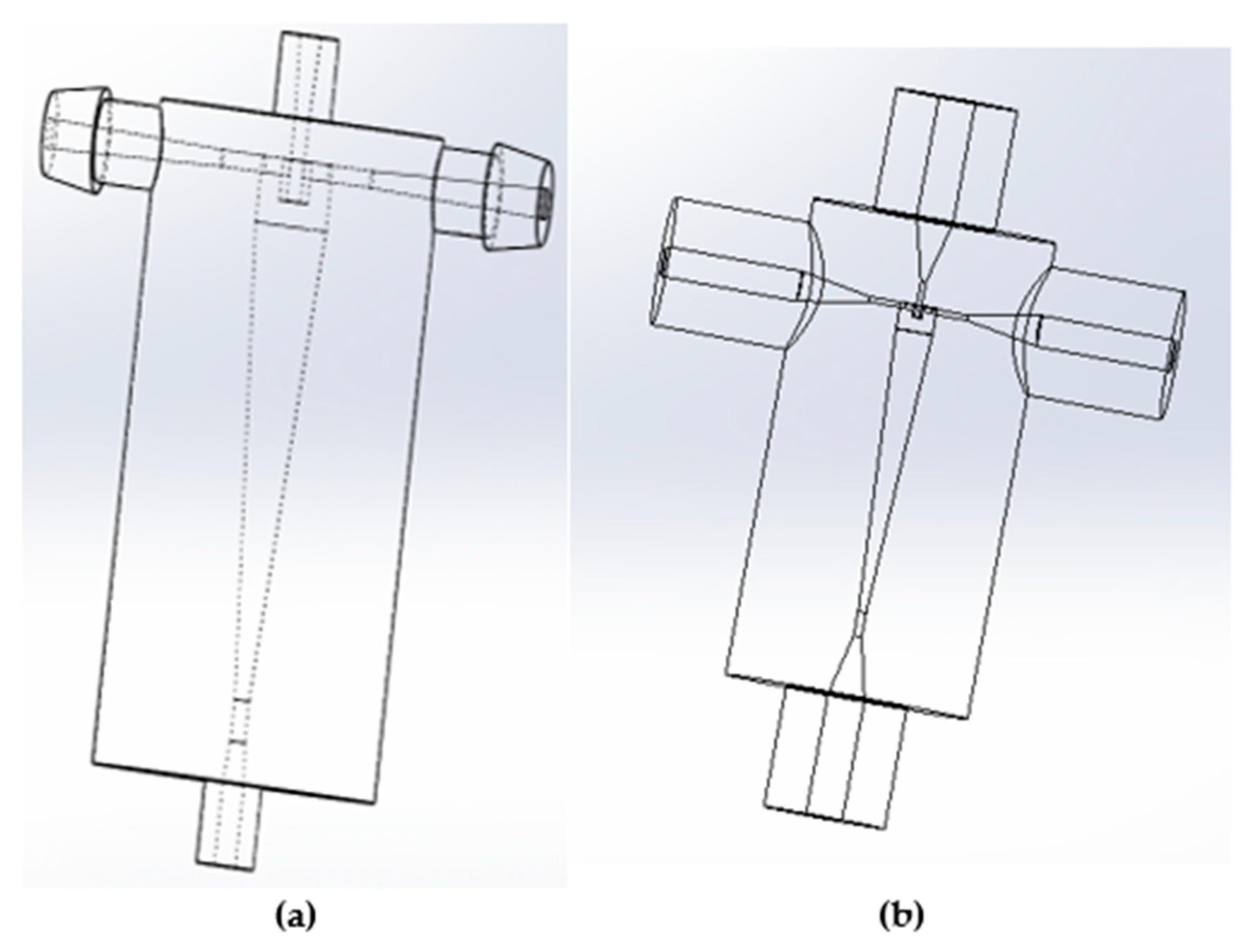
The hydrocyclones in this study were made using Fromlab 3-D printers (Somerville, MA, USA) using gray and clear resins (
Figure 2). The designs were based on the hydrocyclones used in previous bioreactor clarification studies [
17,
18].
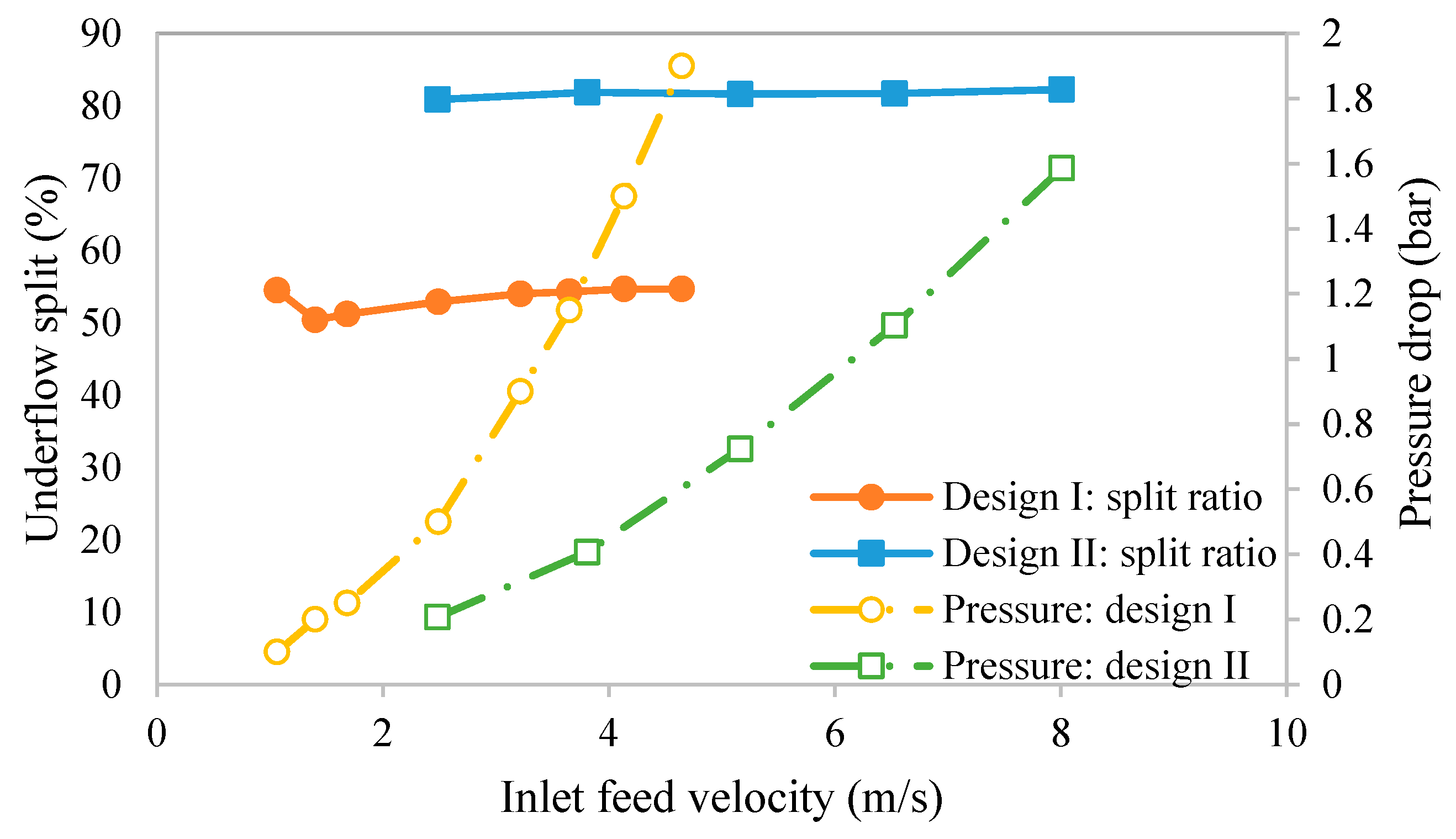
Table 1 shows the design parameters. Design I (larger hydrocyclone) is based on the work by He et al. [
18], while design II is based on the work by Syed et al. [
17]. As can be seen, design I is simpler and has the same inlet and outlet diameters. Both hydrocyclones are based on the Bradley hydrocyclone.
Table 2 compares important design ratios for the two hydrocyclones to the ratios provided by Bradley [
20]. The Bradley hydrocyclones have been shown to provide high separation efficiencies [
19]. As can be seen, both hydrocyclones have elements of Bradley’s optimized ratios. The SolidWorks PDM 2023 software (Cleverbridge, Inc., Chicago, IL, USA) was used to design the hydrocyclones prior to printing, as shown in
Figure 2.
2.4. Experimental Setup and Procedure
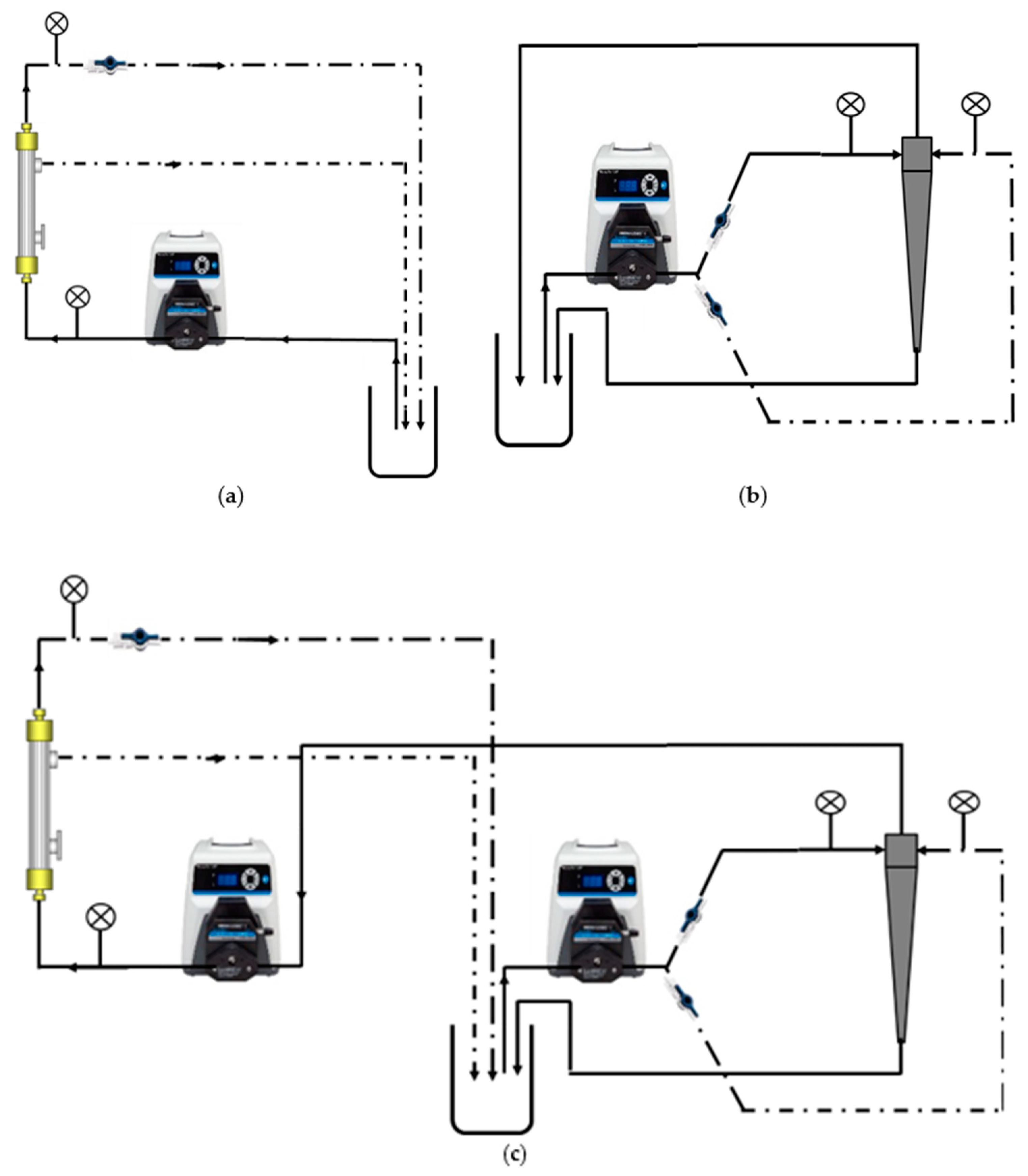
Three different clarification operations were considered: TFF only, hydrocyclone only, and an integrated hydrocyclone and TFF process, as shown in
Figure 3.
Before starting each experiment, the hydrocyclone was washed with 10% bleach followed by DI water. Then, the supplemented media was circulated through the system prior to adding the cell suspension. The TFF filters were also cleaned, regenerated, and washed with PBS, a NaOH/bleach solution, and then DI water, in that order. For the hydrocyclones, prior to testing with the cell suspension, the underflow DI water split ratio was determined using Equation (2).
where
and
are the underflow rate and the feed flow rate, respectively. Various cell densities were investigated. We compare our result to the work of He et al. [
18] and Syed et al. [
17]. He et al. determined the separation efficiency as
where
and
are the cell concentrations in the underflow and overflow, respectively. Syed et al. defined the separation efficiency differently as
where
is the cell concentration in the feed. The results obtained here were compared to the respective literature data based on these definitions, given by Equations (3) and (4).
2.5. Bioreactor Harvesting
Prior to use, the microfiltration modules were flushed with 1 L of DI water. The DI water was pumped through the fiber lumen with the permeate line open, enabling water to pass through the retentate and permeate flow paths. The same procedure was used for the UJP and BioOptimal MF SL filters. This filter preparation was not expected to have any effect on filter performance.
The membrane was regenerated after use according to the following protocol. The filter was first flushed with 1–2 L of DI water at room temperature to remove cells and weakly bound debris. The feed was pumped through the fiber lumen and the permeate line was opened, allowing water to pass through the retentate and permeate lines. Next, the membrane was back-flushed (fluid pumped from outside the fibers through the membrane to the fiber lumen) using about 100 mL of 0.5 N NaOH with 3000 ppm NaClO at room temperature. The module was then forward-flushed (i.e., fluid flows from fiber lumen through the membrane to the shell side) using 0.5 N NaOH with 3000 ppm NaClO at 30 mL/min for 30 min at room temperature. Using the same solution composition, the module was back-flushed at 30 mL/min for 30 min. The last two steps were repeated 3–4 times. The filter was then stored overnight in 0.5 N NaOH with 3000 ppm NaClO. Finally, the next day, the filter was flushed (flow from the feed side to the retentate side) with 1–7 L of water until the pH was neutralized. The nominal water flux for the BioOptimal MF-SL was >21,000 L m−2 h−1. For the UJP filter, the nominal water flux was 1200 L m−2 h−1. Both fluxes were at a TMP of 0.1 MPa and a temperature of 25 °C.
Two sets of TFF experiments were run. The first series of experiments involved running the UJP and BioOptimal MF-SL filters at a wall shear rate of 2000 s−1 (feed flow rate of 16 mL min−1 for the UJP filter and 32 mL min−1 for the BioOptimal MF-SL filter) in concentration mode. A wall shear rate of 2000 s−1 was chosen based on the manufacturer’s recommendations and previous studies. The experiments were run in batch concentration mode. The cell density was 9 million/mL and the feed volume was 50 mL. The initial transmembrane pressure (TMP) was 3.4 kPa (0.5 psi) and 13 kPa (2 psi) for the BioOptimal MF-SL and UJP filters, respectively. It is essential that the BioOptimal is run at a low TMP in order to prevent compaction of the stabilized cake layer within the more open membrane pore structure that faces the feed stream. These TMP values resulted in an initial permeate flux of 1100 L m−2 h−1 for both modules. Experiments were also run at different cell viabilities using the BioOptimal MF-SL filter under the same experimental conditions. The cell viability was decreased by reducing the rate of nutrient addition. The experiments were designed to investigate the effect of the reverse asymmetric membrane structure on flux decline.
The second set of TFF experiments was run with and without an integrated hydrocyclone. These experiments were run in total recycle mode. The feed flow rate to the hyrocyclone was 50 mL min−1. The overflow from the hydrocyclone was introduced to the TFF module at a feed flow rate of 10 mL min−1, corresponding to wall shear rates of 620 s−1 and 1280 s−1 for the BioOptimal MF-SL and UJP filters, respectively. The initial TMP for TFF only (without the hydrocyclone) was 3.7 ± 0.14 kPa (0.54 ± 0.02 psi) for the BioOptimal MF-SL and 12.4 ± 1.3 kPa (1.8 ± 0.19 psi) for the UJP filter. For the integrated system, the TMP was 4.0 ± 0.41 kPa (0.58 ± 0.06) and 12.1 ± 0.83 kPa (1.76 ± 0.12 psi) for the BioOptimal and UJP modules, respectively.
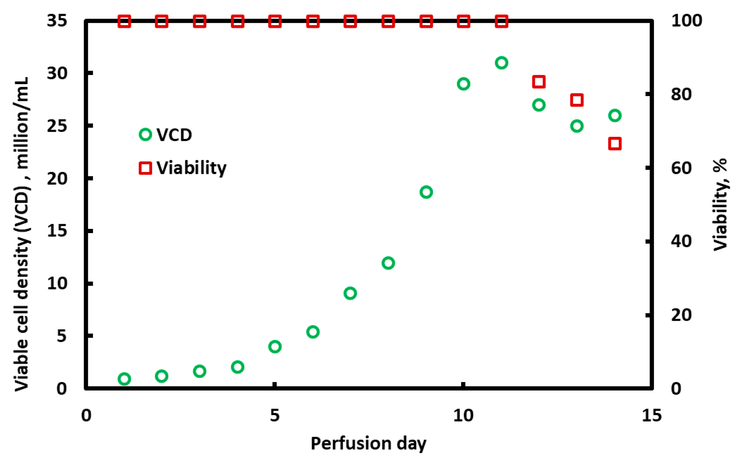
Additional experiments were conducted using the BioOptimal MF-SL filter in ATF mode. A Repligen (Waltham, MA, USA) alternating tangential flow-2 (ATF-2) filtration system was used for perfusion system setup. The setup used a diaphragm pump to both withdraw and return the cell suspension to the bioreactor. The perfusion rate was 300 mL min−1, i.e., 300 mL of fluid was pumped in and out of the bioreactor in 1 min. Although no frequency was set, considering that the displacement of one exchange is 120 mL, about 20 s was estimated for 1 displacement (120 mL). The frequency was controlled by the ATF flow rate. The ATF flow rate is the most important parameter. The set points for the pH, temperature, and DO were 7, 37 °C, and 40%. A Sartorius (Göttingen, Germany) BioStat A plus with a starting cell density of 1 million viable cells/mL in a 1.5 L working volume was used. Perfusion was initiated one day after inoculation at 1 reactor volume per day (RV/day). The perfusion rate was then increased to 1.5 RV/day when the cell density approached a value of 10 million viable cells/mL. After that, the perfusion rate was maintained at 1.5 RV/day. The perfusion run was performed for 14 days.
4. Discussion
TFF is a very attractive unit operation for clarification of cell culture media in perfusion bioreactors, as the permeate can typically be introduced directly to the first capture chromatography operation without any additional clarification. Furthermore, TFF can be easily adapted for both batch and continuous clarification. However, membrane fouling is a serious limitation that restricts the practical use of TFF.
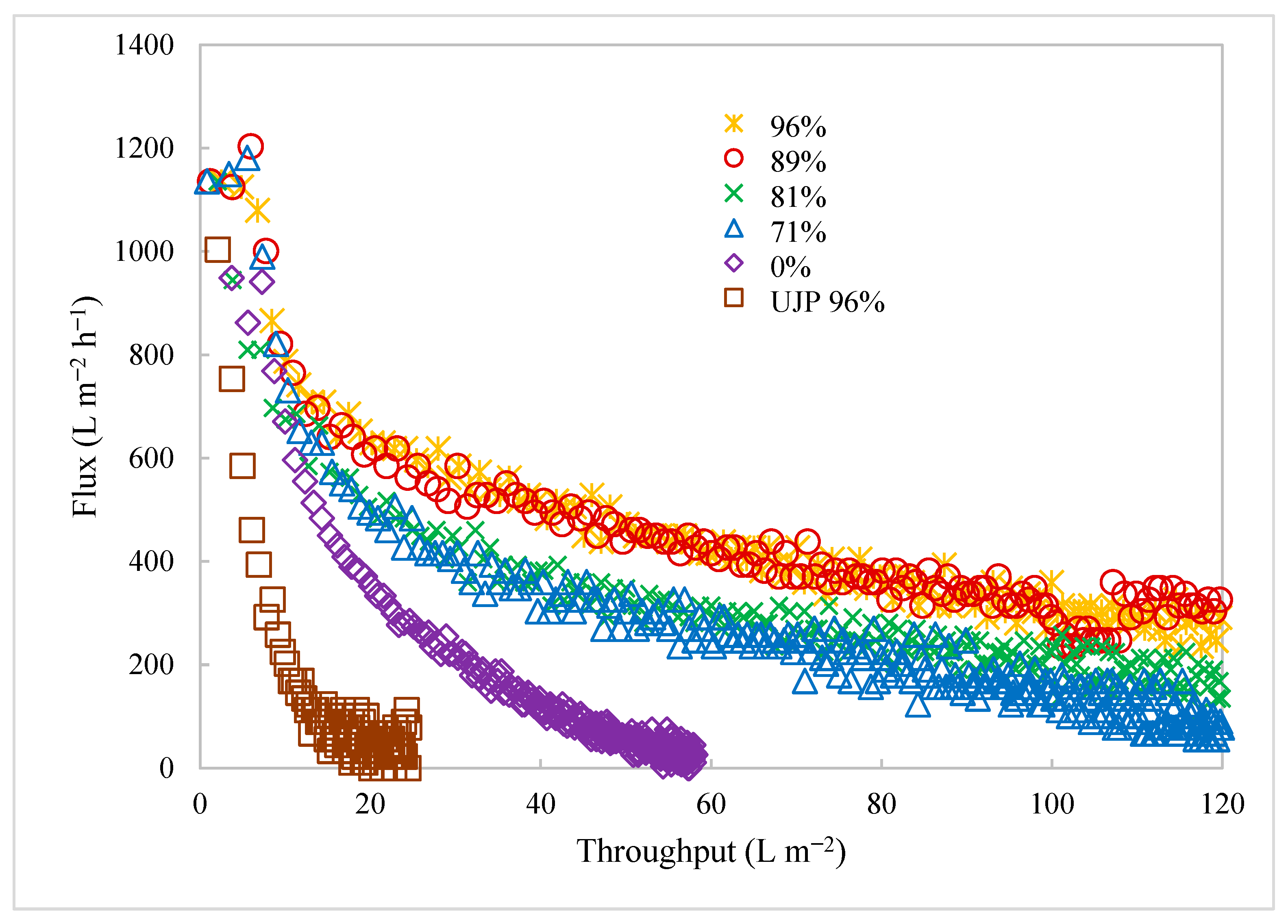
Figure 5 indicates that, for traditional TFF membranes, where the barrier layer faces the feed stream, rapid flux decline occurs due to absorption of foulants and deposition of rejected species directly on or within the barrier layer of the membrane. As shown in
Figure 5 and in our earlier studies [
7,
8], the use of a reverse asymmetric membrane can be beneficial in this application, as the support structure helps stabilize a highly permeable layer of rejected particulate matter. Foulants are removed by this dynamic membrane, thus protecting the barrier layer that faces the permeate stream from membrane fouling. However, as seen in
Figure 5, as the cell viability decreases, cell debris will cause significant fouling even of these reverse asymmetric membranes, leading to a more rapid flux decline and the need to replace the membrane module to enable long-term continuous operations. In a continuous process, the flux would be much lower, but must be maintained for up to 2 months.
Here, for the first time, we combined a hydrocyclone with TFF for clarification of a CHO cell culture. The hydrocyclone provides the primary clarification operation, significantly reducing the particulate concentration in the feed to the TFF module. For traditional TFF membranes where the barrier layer faces the feed, reducing the foulant load in the feed leads to more stable fluxes over a longer time (see
Figure 9b). Note that these experiments were not run under sterile conditions, which limited the duration of the integrated clarification process. It is likely that, if the integrated hydrocyclone–TFF experiments were conducted under sterile conditions for several days, the more stable permeate flux for the integrated process would be more significant when compared to the TFF operation alone.
In contrast, at least over a 2 h period, it appears that the integrated process offers no measurable advantage when using the BioOptimal module for the second clarification step. A similar result was observed in parallel studies, where a BioOptimal module was used in ATF mode for 2 weeks. In this experiment, the permeate flux and the rate of medium addition to the bioreactor were matched: 152 L m
−2 h
−1 for the first 5 days of operation and then 229 L m
−2h
−1 for days 6 to 14 of operations. Both the traditional TFF membranes and the reverse asymmetric membrane showed no flux decline over a 2-week period. ATF has been proposed as another way to suppress membrane fouling. This method typically uses slightly larger-inner-diameter hollow fiber membranes, although any TFF membrane could potentially be used. ATF makes use of altered fluid mechanics and operation at a very low filtrate flux to suppress membrane fouling. A diaphragm pump is used that removes and returns the feed through the same port [
21,
22]. While feed flow reversal leads to suppression of fouling, a disadvantage of the process is that the permeate fluxes are low, resulting in very large membrane surface areas for large-scale commercial operation.
The results obtained here indicate that, for a reverse asymmetric membrane that is more resistant to flux decline, the benefits of an integrated process are likely to be greater at a low cell viability or for extremely long run times, e.g., 2 months. An integrated process may be well suited for continuous biomanufacturing operations, particularly when using conventional TFF membranes in which the size-selective layer faces the cell culture media. Further investigations under sterile conditions for much longer run times will be required in order to determine the effectiveness of integrating a hydrocyclone as the primary clarification step prior to TFF. Nevertheless, the membrane choice will be important (pore size, morphology, asymmetric structure, etc.) for the design and implementation of an optimized two-step clarification process incorporating both a hydrocyclone and a TFF membrane unit.


 and
and 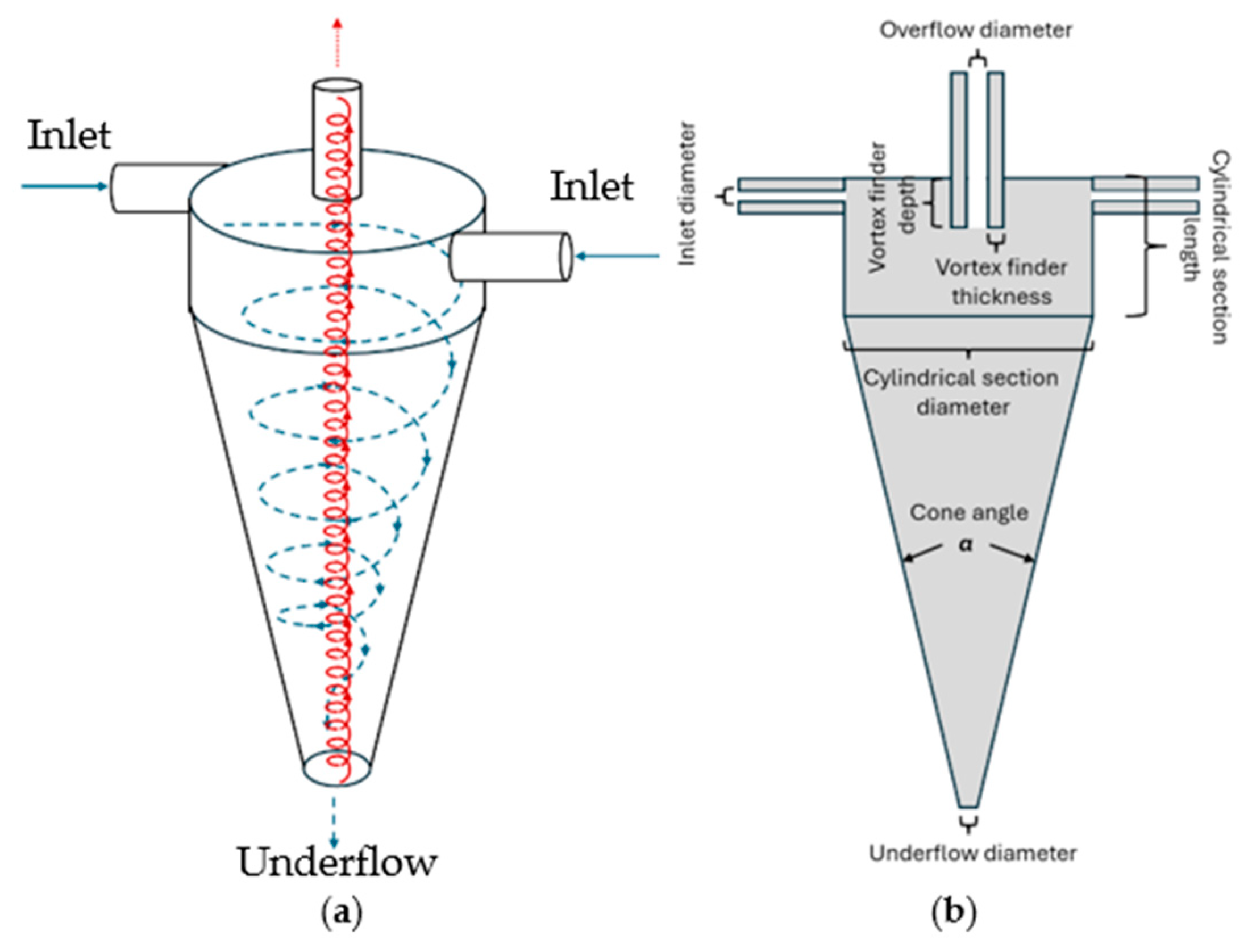


