

Preparation of Chemically Resistant Cellulose Benzoate Hollow Fiber Membrane via Thermally Induced Phase Separation Method


 , ,
, ,  and
and 
Abstract
:1. Introduction
2. Materials and Methods
2.1. Materials
2.2. Solvent Screening
2.3. Phase Separation Temperature Measurement
2.4. Preparation of Hollow Fiber Membrane
2.5. Evaluation of the Prepared Hollow Fiber Membrane
2.5.1. SEM Observation
2.5.2. Pure Water Permeability (PWP)
2.5.3. Particle Rejection
2.5.4. Chlorine Resistance and Alkali Resistance Test
3. Results
3.1. Solvent Screening for Membrane Preparation via TIPS
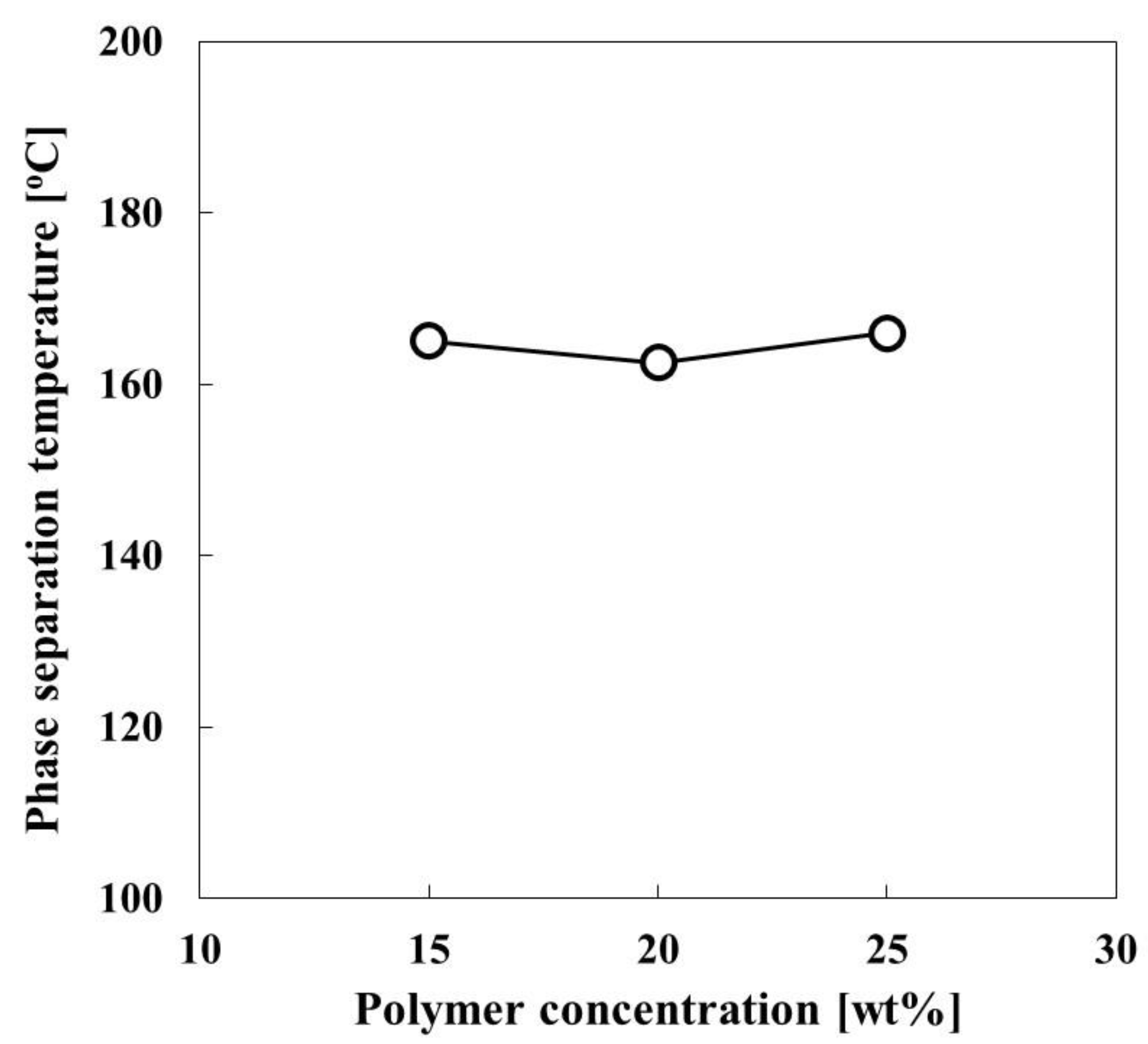
3.2. Phase Diagram of CBzOH/1,3-BG for the TIPS
3.3. Membrane Structure and Performance
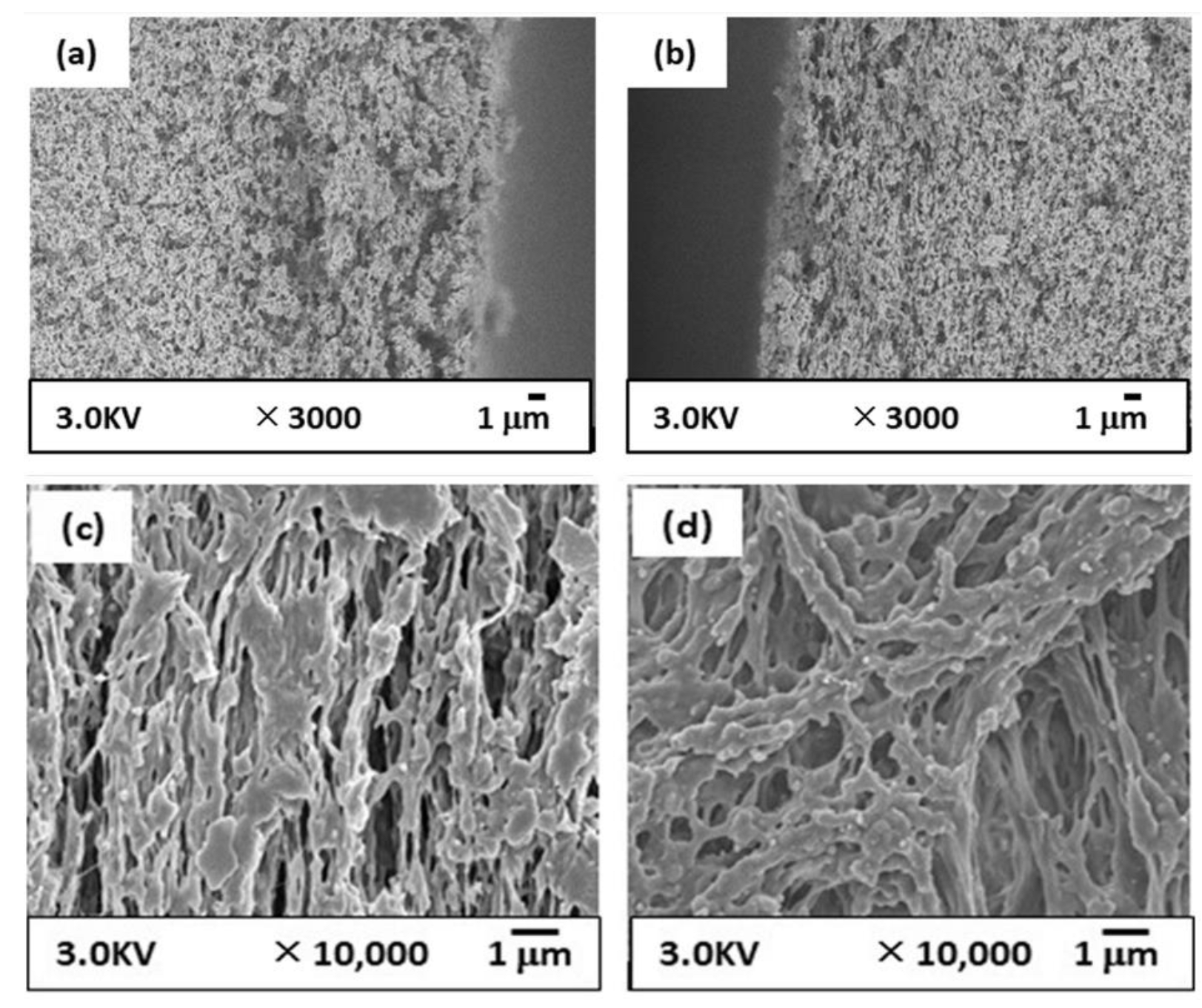
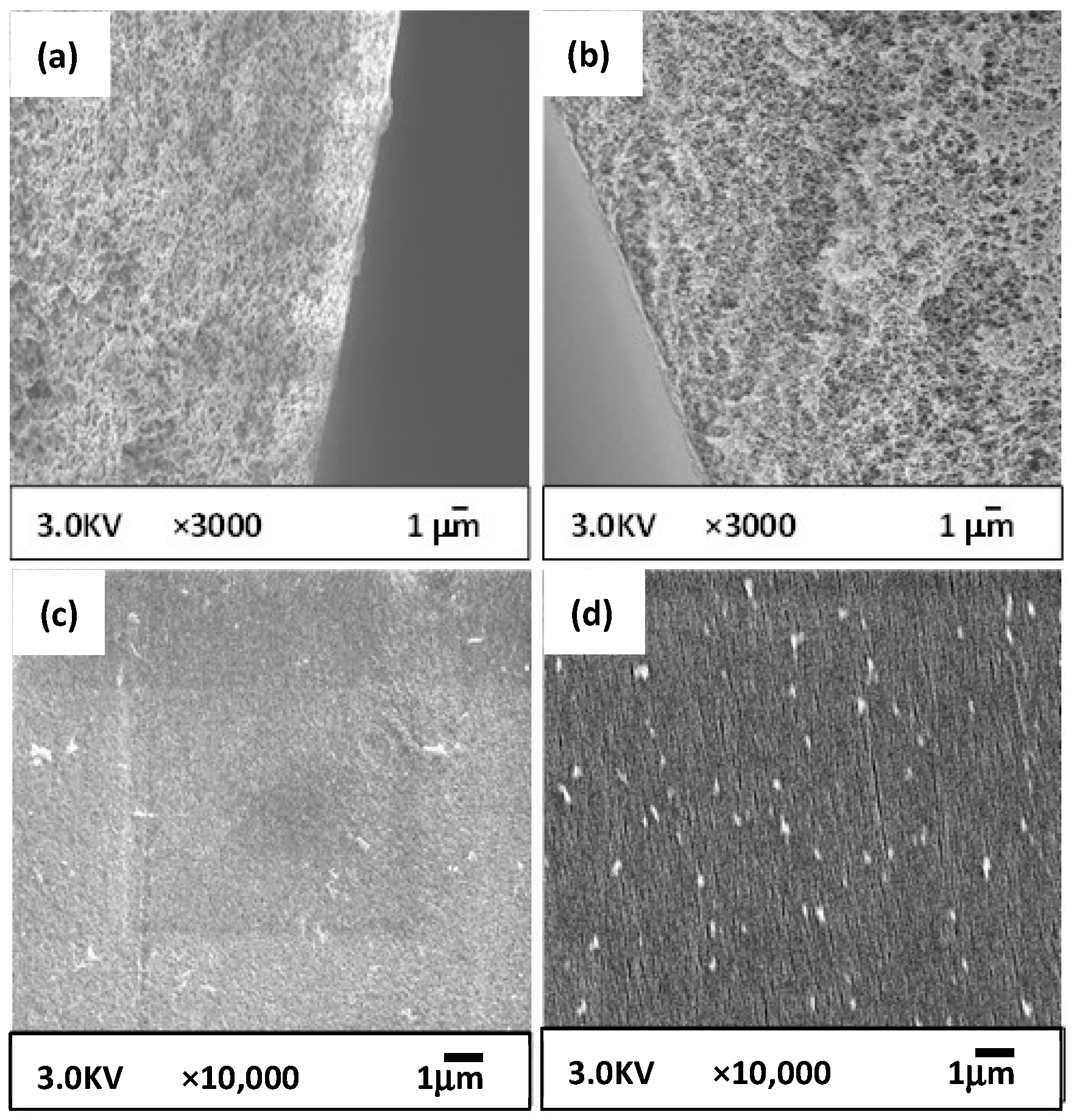
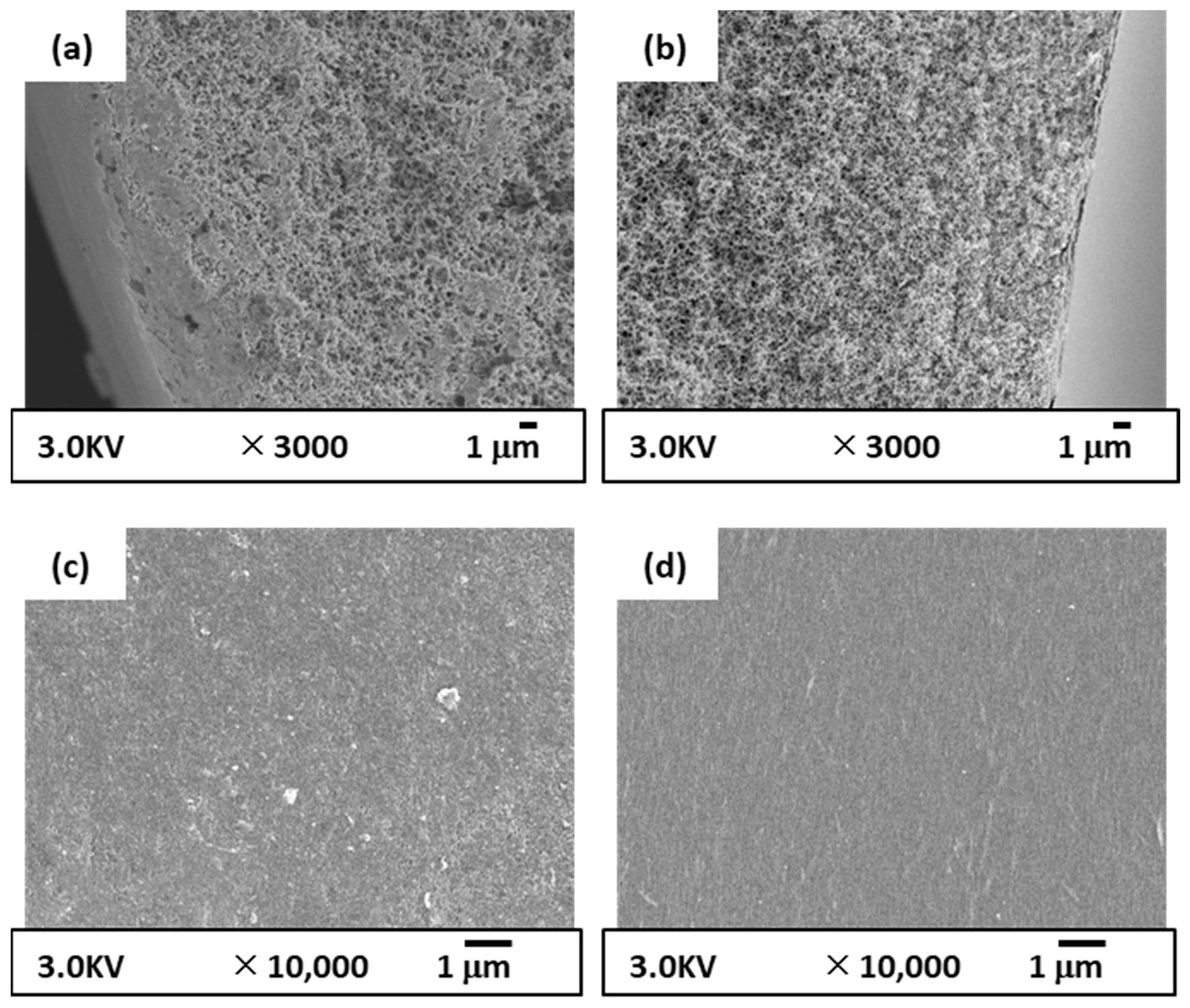
3.3.1. Membrane Structure
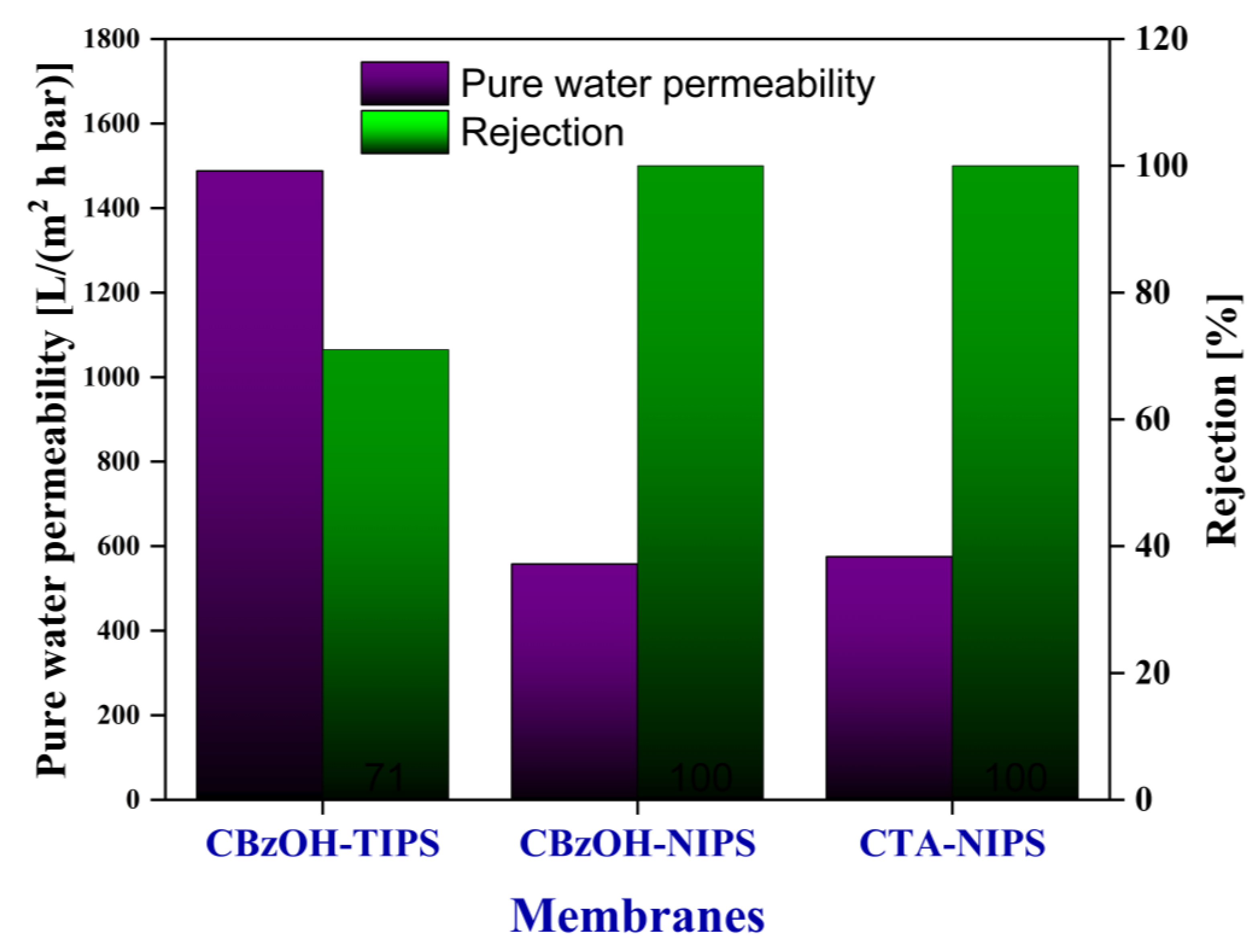
3.3.2. Pure Water Permeability (PWP) and Particle Rejection
3.3.3. Chlorine Resistance
4. Conclusions
Author Contributions
Funding
Institutional Review Board Statement
Informed Consent Statement
Data Availability Statement
Conflicts of Interest
Appendix A
Appendix A.1. Solvent Screening

| Chemicals | δd [(J/cm3)0.5] | δp [(J/cm3)0.5] | δh [(J/cm3)0.5] | δt [(J / cm3)0.5] | Tm * [°C] | |
|---|---|---|---|---|---|---|
| Polymer | Cellulose triacetate (CBzOH) | 20.7 | 4.2 | 12.6 | 24.5 | - |
| Cellulose triacetate (CTA) | 17.2 | 5.2 | 12.0 | 21.7 | 300 | |
| Solvent | Glycerin | 17.4 | 11.3 | 27.2 | 34.2 | 18 |
| 1,5-pentanediol | 17.0 | 8.9 | 19.8 | 31.1 | −16 | |
| 3-Methyl-1,5-pentanediol | 16.7 | 8.1 | 17.6 | 29.5 | No data | |
| Neopentyl glycol (NPG) | 16.3 | 7.1 | 16.6 | 28.4 | 128 | |
| 2-Methyl-2,4-pentanediol | 16.7 | 6.8 | 15.0 | 28.0 | −40 | |
| Diethylene glycol | 16.6 | 12.0 | 19.0 | 27.9 | −7 | |
| 1,3-butylene glycol (1,3-BG) | 16.5 | 8.1 | 20.9 | 27.8 | −77 | |
| Tetraethyl glycol | 16.5 | 9.4 | 15.3 | 27.8 | −6 | |
| Tripropylene glycol | 16.9 | 9.9 | 13.9 | 27.6 | −30 | |
| Triethylene glycol | 16 | 12.5 | 18.6 | 27.5 | - | |
| N-Ethyltoluene Sulfonamide | 18.6 | 13.0 | 7.8 | 27.4 | - | |
| Diethylene glycol monoacetate | 16.7 | 8.4 | 13.7 | 27.3 | −32 | |
| 2-ethyl-1,3-hexanediol (EHD) | 16.4 | 6.2 | 14.0 | 27.1 | −40 | |
| Dimethyl sulfoxide | 18.4 | 16.4 | 10.2 | 26.7 | 18 | |
| sulfolane (SF) | 17.8 | 17.4 | 8.7 | 26.4 | 27 | |
| Dipropylene glycol | 16.5 | 10.6 | 17.7 | 26.4 | −40 | |
| 2,5-dimethyl-2,5-hexanediol | 16.4 | 5.6 | 11.0 | 25.7 | 89 | |
| γ-Butyrolactone | 18.0 | 16.6 | 7.4 | 25.6 | −42 | |
| Dialyl phthalate | 17.8 | 8.5 | 4.0 | 25.5 | - | |
| α-terpineol | 17.1 | 3.6 | 7.6 | 25.3 | 31 | |
| 1,6-Hexanediol | 15.7 | 8.4 | 17.8 | 25.2 | 39 | |
| Tetrahydrofurfuryl acetate | 16.9 | 6.5 | 7.2 | 25.0 | - | |
| Bis phthalate (2-methoxyethyl) | 17.2 | 9.7 | 5.4 | 24.9 | −45 | |
| Diethyl maleate | 16.7 | 5.6 | 7.6 | 24.8 | −10 | |
| Diethyl fumarate | 16.7 | 5.6 | 7.6 | 24.8 | 2 | |
| Mentanol | 16.8 | 3.5 | 6.6 | 24.7 | 35 | |
| Propylene glycol diacetate | 16.4 | 5.5 | 7.9 | 24.5 | −75 | |
| 1,4-Butanediol diacetate | 16.4 | 5.5 | 7.4 | 24.3 | - | |
| 1,3-butylene glycol diacetate | 16.4 | 5.2 | 7.4 | 24.3 | - | |
| Ethyl lactate acetate | 16.3 | 5.5 | 7.6 | 24.3 | - | |
| Tarpinyl acetate | 16.7 | 2.8 | 4.2 | 24.0 | <−80 | |
| Polyethylene glycol(6000) | 16.5 | 6.9 | 4.8 | 23.8 | 62 | |
| Tripropylene glycol-methyl-n-propyl ether | 15.9 | 6.2 | 7.1 | 23.6 | - | |
| Diisobutyl fumarate | 16.2 | 3.6 | 5.3 | 23.5 | 8 | |
| Dihydrotestosterone acetate | 16.4 | 2.7 | 3.4 | 23.4 | - | |
| Dipropylene glycol methyl-n-propyl ether | 15.6 | 4.3 | 4.1 | 22.4 | −14.5 | |
| Dipropylene glycol-methyl-isopentyl ether | 15.5 | 3.7 | 3.7 | 22.2 | - | |
| Triethyl phosphate | 16.7 | 11.4 | 9.2 | 22.2 | - | |
| Dimethyl phthalate | 18.6 | 10.8 | 4.9 | 22.1 | 5.5 | |
| 1,1,3,3-tetramethylurea | 16.7 | 8.2 | 11.0 | 21.6 | - | |
| Trimethyl phosphate | 15.7 | 10.5 | 10.2 | 21.5 | −46 | |
| Triethyl citrate | 16.5 | 4.9 | 12.0 | 21.0 | -45 | |
| Dipropylene glycol methyl ether | 15.5 | 5.7 | 11.2 | 20.0 | −25.2 | |
| Dipropylene glycol n-propyl ether | 15.6 | 6.1 | 11.0 | 20.0 | <−80 | |
| Diethyl phthalate | 17.6 | 9.6 | 4.5 | 20.5 | −41 | |
| Di-n-butyl phthalate | 17.8 | 8.6 | 4.1 | 20.2 | −35 | |
| Diethylene glycol monobutyl ether | 15.7 | 6.5 | 10.0 | 19.7 | −68 | |
| Dipropylene glycol n-butyl ether | 15.7 | 6.5 | 10.0 | 19.7 | <−75 | |
| Dimethyl succinate | 16.1 | 7.7 | 8.8 | 19.9 | 18 | |
| Dimethyl adipate | 16.3 | 6.8 | 8.5 | 19.6 | 10 | |
| Diethyl succinate | 16.2 | 6.8 | 8.7 | 19.6 | - | |
| Glycerol triacetate | 16.5 | 4.5 | 9.1 | 19.4 | −78 | |
| Tripropylene glycol methyl ether | 15.3 | 5.5 | 10.4 | 19.3 | <−78 | |
| Bis sebacate (2-ethylhexyl) | 16.2 | 5.0 | 9.0 | 19.2 | −67 | |
| Diethyl adipic acid | 16.4 | 6.2 | 7.5 | 19.1 | −20 | |
| o-Triethyl Acetyl Citrate | 16.6 | 3.5 | 8.6 | 19.0 | - | |
| Dipropylene glycol methyl ether acetate | 16.3 | 4.9 | 8.0 | 18.8 | −25 | |
| Bis phthalate (2-ethylhexyl) | 16.6 | 7.0 | 3.1 | 18.3 | −50 | |
| Di-n-butyl fumarate | 16.7 | 3.0 | 6.7 | 18.2 | −35 | |
| Tributyl phosphate | 16.3 | 6.3 | 4.3 | 18.0 | −79 | |
| Di-n-butyl sebacate | 16.7 | 4.5 | 4.1 | 17.8 | −11 | |
| Solvent | Ra [(J/cm3)0.5] |
|---|---|
| 1,5-pentanediol | 10.2 |
| Neopentyl glycol (NPG) | 10.0 |
| 2-Methyl-2,4-pentanediol | 8.7 |
| Diethylene glycol | 13.0 |
| 1,3-butylene glycol (1,3-BG) | 12.4 |
| Tetraethyl glycol | 10.3 |
| Tripropylene glycol | 9.5 |
| Triethylene glycol | 13.9 |
| N-Ethyltoluene Sulfonamide | 10.8 |
| Diethylene glycol monoacetate | 9.0 |
| 2-ethyl-1,3-hexanediol (EHD) | 8.9 |
| Dimethyl sulfoxide | 13.2 |
| sulfolane (SF) | 14.9 |
| Dipropylene glycol | 11.7 |
| 2,5-dimethyl-2,5-hexanediol | 8.8 |
| γ-Butyrolactone | 14.4 |
| Dialyl phthalate | 11.1 |
| α-terpineol | 8.7 |
| 1,6-Hexanediol | 12.0 |
| Tetrahydrofurfuryl acetate | 9.5 |
| Diethyl maleate | 9.4 |
| Diethyl fumarate | 9.4 |
| Propylene glycol diacetate | 9.8 |
| 1,4-Butanediol diacetate | 10.0 |
| 1,3-butylene glycol diacetate | 10.0 |
| Ethyl lactate acetate | 10.1 |
| Triethyl phosphate | 11.2 |
| Dimethyl phthalate | 10.9 |
| 1,1,3,3-tetramethylurea | 9.0 |
| Trimethyl phosphate | 12.0 |
| Dipropylene glycol methyl ether | 10.5 |
| Diethyl phthalate | 11.5 |
| Di-n-butyl phthalate | 11.1 |
| Diethylene glycol monobutyl ether | 10.5 |
| Dimethyl succinate | 10.5 |
| Dimethyl adipate | 10.0 |
| Diethyl succinate | 10.1 |
| Glycerol Triacetate (Triacetin) | 9.0 |
| Tripropylene glycol methyl ether | 11.0 |
| Diethyl adipic acid | 10.1 |
| o-Triethyl Acetyl Citrate | 9.1 |
| Tributyl phosphate | 12.2 |
| Solvent | Ra [(J/cm3)0.5] |
|---|---|
| 3-methyl-1,5-pentanediol | 10.2 |
| 2-Methyl-2,4-pentanediol | 8.7 |
| 1,3-BG | 12.4 |
| Tripropylene glycol | 9.5 |
| EHD | 8.9 |
| Dipropylene glycol | 11.7 |
| 2,5-dimethyl-2,5-hexanediol | 8.8 |
| α-terpineol | 8.7 |
| δd [(J/cm3)0.5] | δp [(J/cm3)0.5] | δh [(J/cm3)0.5] | δt [(J/cm3)0.5] | Tm * [°C] | ||
|---|---|---|---|---|---|---|
| Polymer | ||||||
| CBzOH | 20.7 | 4.2 | 12.6 | 24.5 | - | |
| Solvent | ||||||
| 1,3-BG | 16.5 | 8.1 | 20.9 | 27.8 | −77 | |
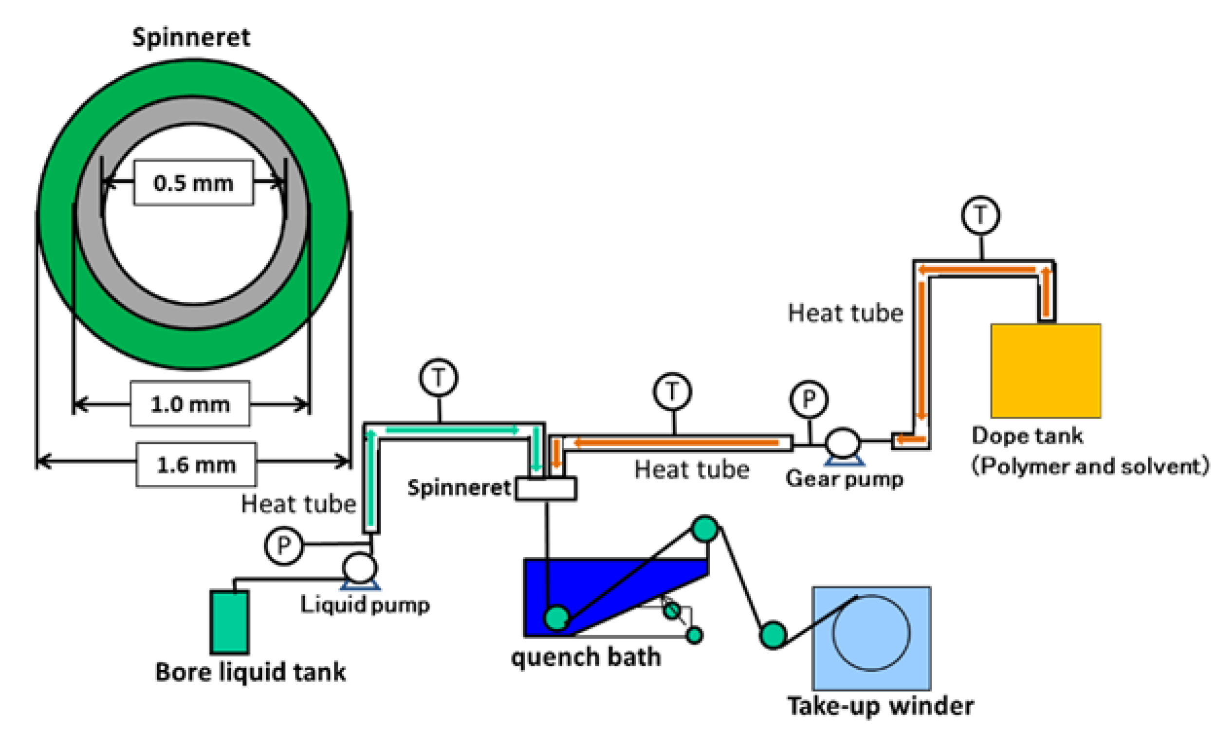
Appendix A.2. Preparation of Hollow Fiber Membrane via Non-Solvent Induces Phase Separation (NIPS)
| Preparation Conditions | Parameters | |
|---|---|---|
| Polymer solution composition [wt%] | CBzOH/DMSO | 14/86 |
| CTA/DMSO | 17/83 | |
| Dope tank temperature [°C] | 85~90 °C | |
| Gear pump temperature [°C] | 90 °C | |
| Dope solution flow rate [g/min] | 14 g/min for CBzOH membrane | |
| Bore liquid | Water | |
| Bore liquid flow rate [g/min] | 10 g/min for CBzOH membrane | |
| Air gap [mm] | 25 | |
| Quenching bath liquid | Water | |
| Quenching bath temperature [°C] | 90 °C | |
| Take-up speed [m/min] | 9 m/min for CBzOH membrane | |


| Membranes | Water Contact Angle (°) |
|---|---|
| CBzOH | 76.2 ± 0.8 |
| CBzOH NaClO treated | 73.2 ± 0.8 |
| CTA | 58.4 ± 0.7 |
| CTA NaClO treated | 35.9 ± 0.5 |
References
- Ren, J.; Wang, R. Preparation of Polymeric Membranes. In Membrane and Desalination Technologies, Handbook of Environmental Engineering; Wang, L.K., Chen, J.P., Hung, Y.-T., Shammas, N.K., Eds.; Humana Press: Totowa, NJ, USA, 2008; Volume 13, pp. 47–100. [Google Scholar]
- Mulder, M. Basic Principles of Membrane Technology; Kluwer Academic Publisher: Amsterdam, The Netherlands, 1997. [Google Scholar]
- Lu, X.; Elimelech, M. Fabrication of desalination membranes by interfacial polymerization: History, current efforts, and future directions. Chem. Soc. Rev. 2021, 50, 6290–6307. [Google Scholar] [CrossRef] [PubMed]
- Ji, C.; Zhai, Z.; Jiang, C.; Hu, P.; Zhao, S.; Xue, S.; Yang, Z.; He, T.; Niu, Q.J. Recent advances in high-performance TFC membranes: A review of the functional interlayers. Desalination 2021, 500, 114869. [Google Scholar] [CrossRef]
- Cui, Z.; Drioli, E.; Lee, Y.M. Recent progress in fluoropolymers for membranes. Prog. Polym. Sci. 2014, 39, 164–198. [Google Scholar] [CrossRef]
- Peng, N.; Widjojo, N.; Sukitpaneenit, P.; Teoh, M.M.; Lipscomb, G.G.; Chung, T.-S.; Lai, J.-Y. Evolution of polymeric hollow fibers as sustainable technologies: Past, present, and future. Prog. Polym. Sci. 2012, 37, 1401–1424. [Google Scholar] [CrossRef]
- Ulbricht, M. Advanced functional polymer membranes. Polymer 2006, 47, 2217–2262. [Google Scholar] [CrossRef]
- Ul-Islam, M.; Ul-Islam, S.; Yasir, S.; Fatima, A.; Ahmed, W.; Lee, Y.S.; Manan, S.; Ullah, M.W. Potential Applications of Bacterial Cellulose in Environmental and Pharmaceutical Sectors. Curr. Pharm. Des. 2020, 26, 5793–5806. [Google Scholar] [CrossRef] [PubMed]
- Peng, B.L.; Yao, Z.L.; Wang, X.C.; Crombeen, M.; Sweeney, D.G.; Tam, K.C. Cellulose-based materials in wastewater treatment of petroleum industry. Green Energy Environ. 2020, 5, 37–49. [Google Scholar] [CrossRef]
- Mollahosseini, A.; Abdelrasoul, A.; Shoker, A. A critical review of recent advances in hemodialysis membranes hemocompatibility and guidelines for future development. Mater. Chem. Phys. 2020, 248, 122911. [Google Scholar] [CrossRef]
- Wang, D. A critical review of cellulose-based nanomaterials for water purification in industrial processes. Cellulose 2019, 26, 687–701. [Google Scholar] [CrossRef]
- Douglass, E.F.; Avci, H.; Boy, R.; Rojas, O.J.; Kotek, R. A Review of Cellulose and Cellulose Blends for Preparation of Bio-derived and Conventional Membranes, Nanostructured Thin Films, and Composites. Polym. Rev. 2018, 58, 102–163. [Google Scholar] [CrossRef]
- Lu, P.; Gao, Y.; Umar, A.; Zhou, T.; Wang, J.; Zhang, Z.; Huang, L.; Wang, Q. Recent Advances in Cellulose-Based Forward Osmosis Membrane. Sci. Adv. Mater. 2015, 7, 2182–2192. [Google Scholar] [CrossRef]
- Loeb, S.; Sourirajan, S. Sea Water Demineralization by Means of an Osmotic Membrane. In Saline Water Conversion—II; Advances in Chemistry; American Chemical Society: Washington, DC, USA, 1963; Volume 38, pp. 117–132. [Google Scholar]
- Uemura, T.; Kurihara, M. Chlorine Resistance of Reverse Osmosis Membranes and Changes in Membrane Structure and Performance Caused by Chlorination Degradation. Bull. Soc. Sea Water Sci. Jpn. 2003, 57, 498–507. [Google Scholar] [CrossRef]
- Ohya, H. Deterioration of Asymmetric Cellulose Acetate Membrane with Sodium Hypochlorite-Structural and Chemical Change. Kagaku-Kougakuronbunshu 1981, 7, 267–271. [Google Scholar] [CrossRef]
- Hashizume, T.; Okamoto, Y.; Nagai, K.; Shimamoto, S. Mechanism of sodium-hypochlorite-induced degradation of cellulose acetate and the enhancement of its degradation resistance by chemical modification. Text. Res. J. 2022, 92, 2487–2500. [Google Scholar] [CrossRef]
- Doelker, E. Cellulose derivatives. In Proceedings of the Biopolymers I; Springer: Berlin/Heidelberg, Germany, 1993; pp. 199–265. [Google Scholar]
- Budtova, T.; Navard, P. Cellulose in NaOH–water based solvents: A review. Cellulose 2016, 23, 5–55. [Google Scholar] [CrossRef]
- Arkhangelsky, E.; Kuzmenko, D.; Gitis, N.V.; Vinogradov, M.; Kuiry, S.; Gitis, V. Hypochlorite Cleaning Causes Degradation of Polymer Membranes. Tribol. Lett. 2007, 28, 109–116. [Google Scholar] [CrossRef]
- Arkhangelsky, E.; Goren, U.; Gitis, V. Retention of organic matter by cellulose acetate membranes cleaned with hypochlorite. Desalination 2008, 223, 97–105. [Google Scholar] [CrossRef]
- Silva, M.A.; Belmonte-Reche, E.; de Amorim, M.T.P. Morphology and water flux of produced cellulose acetate membranes reinforced by the design of experiments (DOE). Carbohydr. Polym. 2021, 254, 117407. [Google Scholar] [CrossRef]
- Guillen, G.R.; Pan, Y.; Li, M.; Hoek, E.M.V. Preparation and Characterization of Membranes Formed by Nonsolvent Induced Phase Separation: A Review. Ind. Eng. Chem. Res. 2011, 50, 3798–3817. [Google Scholar] [CrossRef]
- Vyas, M.D.; Mody, I.C. Morphological study of cellulose acetate benzoate membranes by scanning electron microscopy. Desalination 1982, 42, 107–114. [Google Scholar] [CrossRef]
- Vyas, M.D.; Mody, R.C.; Mody, I.C. Development and characterization of cellulose-acetate benzoate flat osmotic membranes. J. Appl. Polym. Sci. 1994, 52, 1031–1035. [Google Scholar] [CrossRef]
- Takao, S.; Rajabzadeh, S.; Otsubo, C.; Hamada, T.; Kato, N.; Nakagawa, K.; Shintani, T.; Matsuyama, H.; Yoshioka, T. Preparation of Cellulose Triacetate Microfiltration Hollow Fiber Membranes by Thermally Induced Phase Separation. ACS Omega 2022, 7, 33783–33792. [Google Scholar] [CrossRef] [PubMed]
- Hansen, C.M. Hansen Solubility Parameters. A User’s Handbook, 2nd ed.; CRC Press: Boca Raton, FL, USA, 2007. [Google Scholar]
- Shang, M.; Matsuyama, H.; Teramoto, M.; Lloyd, D.R.; Kubota, N. Preparation and membrane performance of poly(ethylene-co-vinyl alcohol) hollow fiber membrane via thermally induced phase separation. Polymer 2003, 44, 7441–7447. [Google Scholar] [CrossRef]
- Shibutani, T.; Kitaura, T.; Ohmukai, Y.; Maruyama, T.; Nakatsuka, S.; Watabe, T.; Matsuyama, H. Membrane fouling properties of hollow fiber membranes prepared from cellulose acetate derivatives. J. Membr. Sci. 2011, 376, 102–109. [Google Scholar] [CrossRef]
- Fu, X.Y.; Sotani, T.; Matsuyama, H. Effect of membrane preparation method on the outer surface roughness of cellulose acetate butyrate hollow fiber membrane. Desalination 2008, 233, 10–18. [Google Scholar] [CrossRef]
- Ho, N.A.D.; Leo, C.P. A review on the emerging applications of cellulose, cellulose derivatives and nanocellulose in carbon capture. Environ. Res. 2021, 197, 111100. [Google Scholar] [CrossRef] [PubMed]
- Yu, Y.; Wu, Q.-Y.; Liang, H.-Q.; Gu, L.; Xu, Z.-K. Preparation and characterization of cellulose triacetate membranes via thermally induced phase separation. J. Appl. Polym. Sci. 2017, 134, 44454. [Google Scholar] [CrossRef]
- Xing, X.-Y.; Gu, L.; Jin, Y.; Sun, R.; Xie, M.-Y.; Wu, Q.-Y. Fabrication and characterization of cellulose triacetate porous membranes by combined nonsolvent-thermally induced phase separation. Cellulose 2019, 26, 3747–3762. [Google Scholar] [CrossRef]
- Matsuyama, H.; Ohga, K.; Maki, T.; Tearamoto, M.; Nakatsuka, S. Porous cellulose acetate membrane prepared by thermally induced phase separation. J. Appl. Polym. Sci. 2003, 89, 3951–3955. [Google Scholar] [CrossRef]
- Nguyen, T.P.N.; Yun, E.-T.; Kim, I.-C.; Kwon, Y.-N. Preparation of cellulose triacetate/cellulose acetate (CTA/CA)-based membranes for forward osmosis. J. Membr. Sci. 2013, 433, 49–59. [Google Scholar] [CrossRef]
- Li, H.-J.; Cao, Y.-M.; Qin, J.-J.; Jie, X.-M.; Wang, T.-H.; Liu, J.-H.; Yuan, Q. Development and characterization of anti-fouling cellulose hollow fiber UF membranes for oil–water separation. J. Membr. Sci. 2006, 279, 328–335. [Google Scholar] [CrossRef]
- Rajabzadeh, S.; Maruyama, T.; Sotani, T.; Matsuyama, H. Preparation of PVDF hollow fiber membrane from a ternary polymer/solvent/nonsolvent system via thermally induced phase separation (TIPS) method. Sep. Purif. Technol. 2008, 63, 415–423. [Google Scholar] [CrossRef]
- Zhao, J.; Chong, J.Y.; Shi, L.; Wang, R. Explorations of combined nonsolvent and thermally induced phase separation (N-TIPS) method for fabricating novel PVDF hollow fiber membranes using mixed diluents. J. Membr. Sci. 2019, 572, 210–222. [Google Scholar] [CrossRef]
- Matsuyama, H.; Rajabzadeh, S.; Karkhanechi, H.; Jeon, S. PVDF Hollow Fibers Membranes. Compr. Membr. Sci. Eng. 2017, 137–189. [Google Scholar]
- Matsuyama, H.; Karkhanechi, H.; Rajabzadeh, S. Chapter 3—Polymeric membrane fabrication via thermally induced phase separation (TIPS) method. In Hollow Fiber Membranes; Chung, T.-S., Feng, Y., Eds.; Elsevier: Amsterdam, The Netherlands, 2021; pp. 57–83. [Google Scholar]
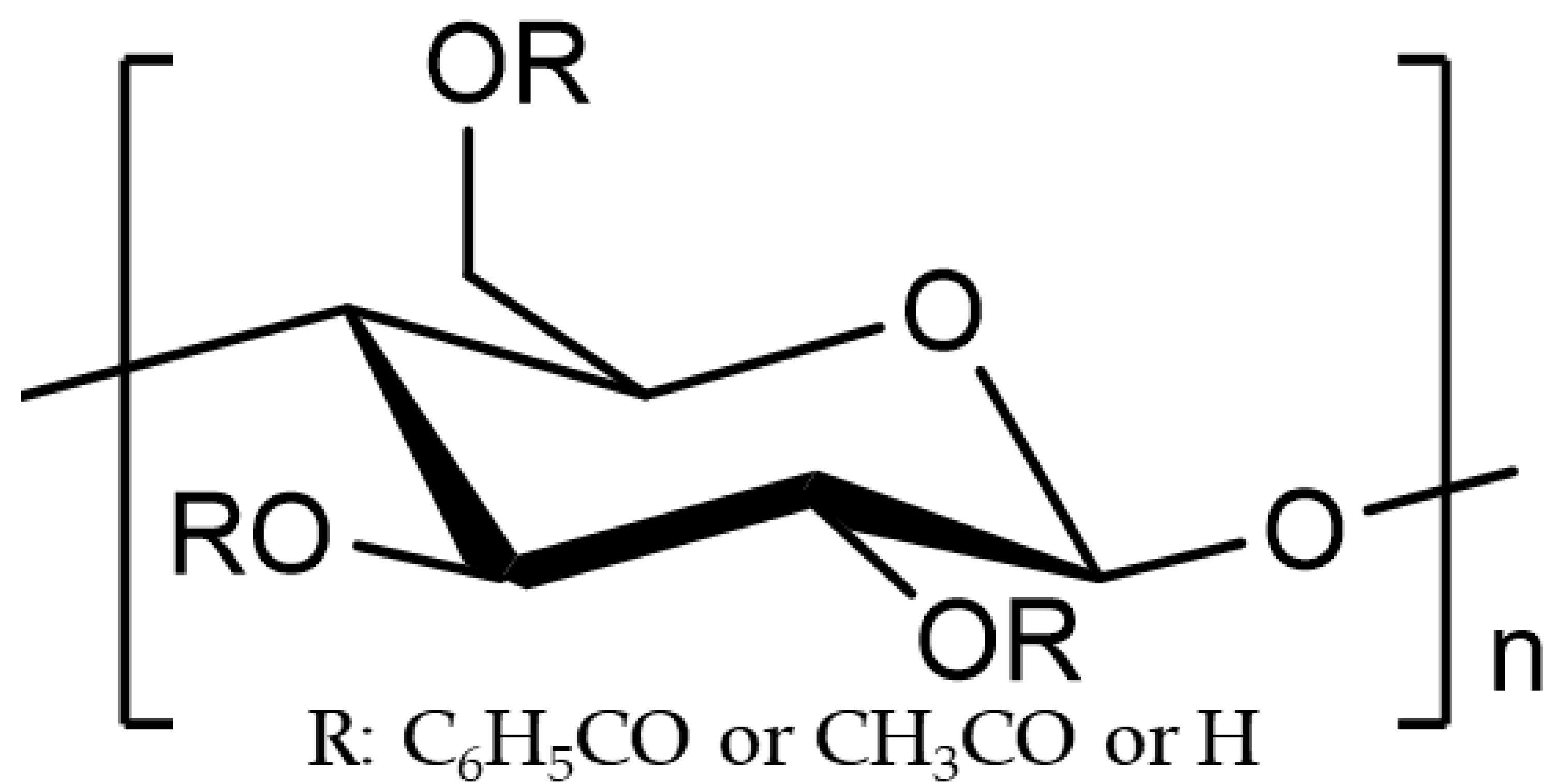

| Polymer | Tm *1 [°C] | Tg *2 [°C] | MW | Substitution Ratio *3 | ||
|---|---|---|---|---|---|---|
| R:C6H5CO | R:CH3CO | R:H | ||||
| CBzOH | - | 196 | 578,846 | 2.1 | - | 0.9 |
| CTA | 300 | - | 405,000 | - | 2.87 | 0.13 |
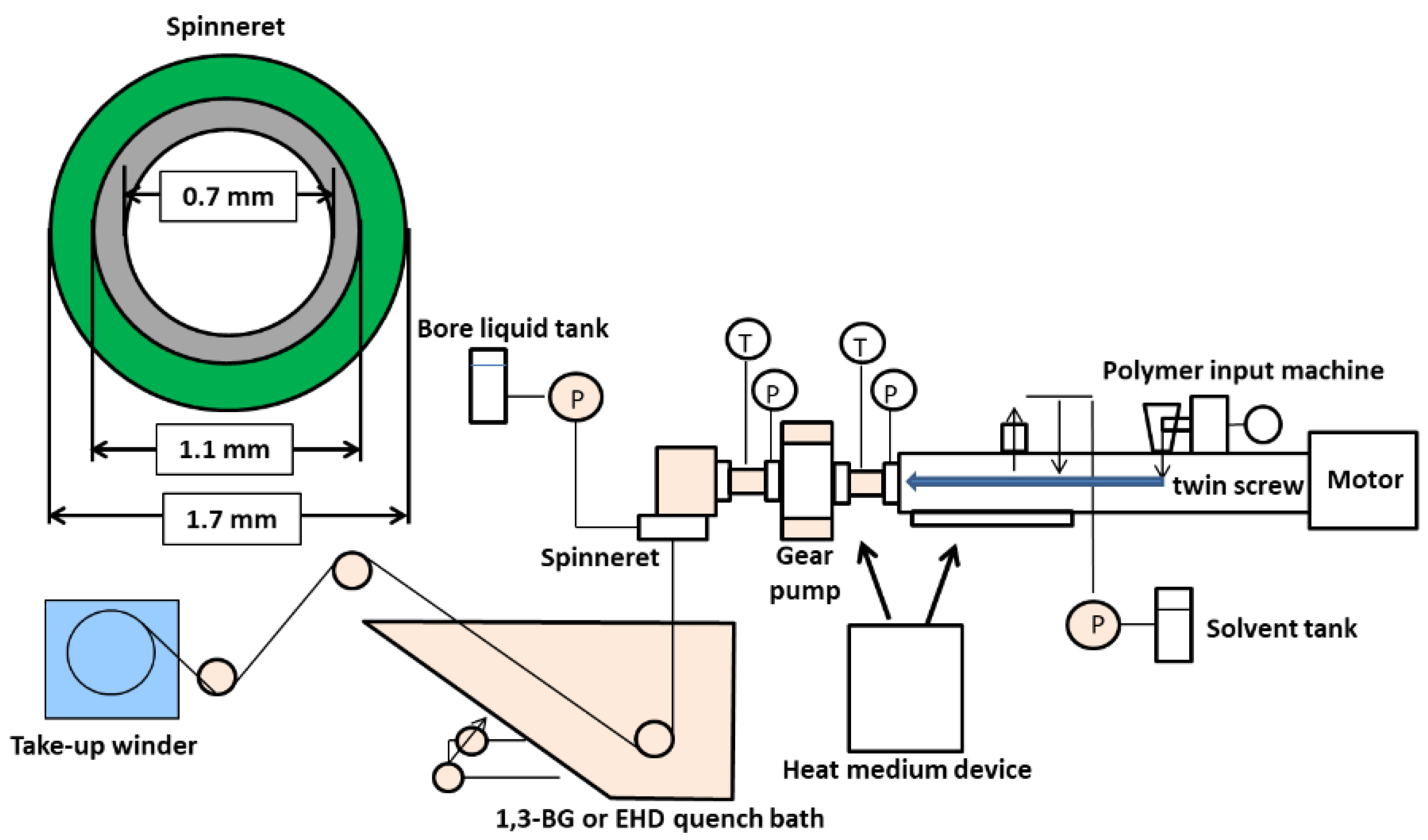
| Preparation Conditions | Parameters | |
|---|---|---|
| Polymer solution composition [wt%] | CBzOH/1,3-BG | 22/78 |
| Screw temperature [°C] | 189 °C | |
| Screw speed [rpm] | 52 rpm | |
| Polymer solution extruded rate [g/min] | 28 g/min | |
| Bore liquid | 1,3-BG | |
| Bore liquid flow rate [g/min] | 14 g/min | |
| Air gap [mm] | 0 | |
| Quenching bath liquid | 1,3-BG/water = 95 wt%/5 wt% | |
| Quenching bath temperature [°C] | 26 °C | |
| Take-up speed [m/min] | 30 g/min | |
Publisher’s Note: MDPI stays neutral with regard to jurisdictional claims in published maps and institutional affiliations. |
© 2022 by the authors. Licensee MDPI, Basel, Switzerland. This article is an open access article distributed under the terms and conditions of the Creative Commons Attribution (CC BY) license (https://creativecommons.org/licenses/by/4.0/).
Share and Cite
Takao, S.; Rajabzadeh, S.; Shibata, M.; Otsubo, C.; Hamada, T.; Kato, N.; Nakagawa, K.; Kitagawa, T.; Matsuyama, H.; Yoshioka, T. Preparation of Chemically Resistant Cellulose Benzoate Hollow Fiber Membrane via Thermally Induced Phase Separation Method. Membranes 2022, 12, 1199. https://doi.org/10.3390/membranes12121199
Takao S, Rajabzadeh S, Shibata M, Otsubo C, Hamada T, Kato N, Nakagawa K, Kitagawa T, Matsuyama H, Yoshioka T. Preparation of Chemically Resistant Cellulose Benzoate Hollow Fiber Membrane via Thermally Induced Phase Separation Method. Membranes. 2022; 12(12):1199. https://doi.org/10.3390/membranes12121199
Chicago/Turabian StyleTakao, Shota, Saeid Rajabzadeh, Masahide Shibata, Chihiro Otsubo, Toyozo Hamada, Noriaki Kato, Keizo Nakagawa, Tooru Kitagawa, Hideto Matsuyama, and Tomohisa Yoshioka. 2022. "Preparation of Chemically Resistant Cellulose Benzoate Hollow Fiber Membrane via Thermally Induced Phase Separation Method" Membranes 12, no. 12: 1199. https://doi.org/10.3390/membranes12121199
APA StyleTakao, S., Rajabzadeh, S., Shibata, M., Otsubo, C., Hamada, T., Kato, N., Nakagawa, K., Kitagawa, T., Matsuyama, H., & Yoshioka, T. (2022). Preparation of Chemically Resistant Cellulose Benzoate Hollow Fiber Membrane via Thermally Induced Phase Separation Method. Membranes, 12(12), 1199. https://doi.org/10.3390/membranes12121199