2.2.1. Critical Buckling Stress under Pure Shear
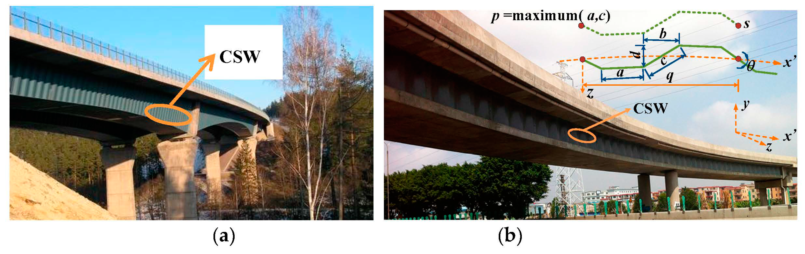
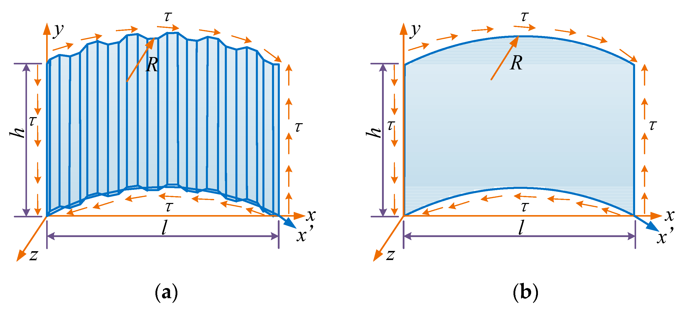
According to the theory of thin plates and shells, if the ratio of a shell’s height to its short side is less than 0.2, the shell can be analyzed as a shallow shell. For HCGs with vertical CSWs, webs always meet this condition and can be treated as orthotropic cylindrical shallow shells (
Figure 2) for the global shear buckling analysis.
According to the stability theory of plates and shells, the equilibrium equation and the deformation compatibility equation of an orthotropic cylindrical shallow shell shown in
Figure 2 under pure shear force can be expressed respectively as Equations (9) and (10) [
30]. In the following equations, the part that appears in bold type shows the difference between a plate and a shell.
where
Φ is the stress function,
w is the out of plane deflection of the shell,
τ is the shear stress,
R is the curvature radius of the HCG.
Substituting Equation (10) into Equation (9), Equation (9) can be expressed as Equation (11).
It can be assumed that the boundary conditions of CSWs satisfy a four-edge simple support, a four-edge fixed support, or the two edges constrained by flanges fixed and the other two edges simply supported (the edges x = 0 and x = l are simply supported, the edges y = 0 and y = h are fixed supported). The functions of deflection can be expressed respectively as Equations (12)–(14).
For a four-edge simple support [
3]:
For a four-edge fixed support [
31]:
For the edges
x = 0 and
x =
l simply supported, and the edges
y = 0 and
y =
h fixed:
where
h is the web height equal to the clear distance between the top and bottom concrete flanges,
l is the web length equal to the linear distance between the two adjacent diaphragm plates.
By substituting Equations (12)–(14) into Equation (11), defining , , , , considering , and according to the Galerkin method, Equation (11) can be simplified as Equations (15)–(17) respectively.
For the four-edge simple support:
For the four-edge fixed support:
For the edges
x = 0 and
x =
l simply supported, and the edges
y = 0 and
y =
h fixed:
By assigning values to m and n in Equations (15)–(17), a series of linear algebraic equations with Aij as unknowns can be obtained. Then the critical shear buckling stress can be derived by assuming the coefficient determinant of the linear algebraic equations equals zero. (i.e., a linear bifurcation analysis).
According to Equations (15)–(17), the elastic global shear buckling stress of CSWs can be expressed as Equation (18):
where
kg is the elastic global shear buckling coefficient of CSWs in HCGs. The detailed solution process of the coefficient
kg,s for a four-edge simple support,
kg,f for a four-edge fixed support,
kg,fs for the edges
x = 0 and
x =
l simply supported, and the edges
y = 0 and
y =
h fixed is given below.
2.2.2. Calculation of Coefficient kg
According to Equations (15)–(18), the global shear buckling coefficient of CSWs in HCGs kg is associated with the length to height ratio λ (l/h), the rigidity ratios α(Dx/Dy) and β(Dxy/Dy), the modulus ratio γ(Gxy/(Ey − 2νyGxy)), the expression h2/(Rd) and 6s/(3a + c).
1. Value ranges of α, β, γ, h2/(Rd) and 6s/(3a + c) for common HCG bridges with CSWs
For trapezoidal CSWs that are commonly used in girder bridges, the rigidity ratios
α and
β have the relationship:
β/α = 2
s2/[(1 +
ν)
q2]. A statistical analysis of available bridges with CSWs (as shown in
Table 1) shows that the rigidity ratio
α varies from 0.0006 to 0.0069,
γ varies from 0.38 to 0.44, 6
s/(3
a +
c) is about 6, and
β is about (1.67~2.0)
α. The following parametric study considers
α ranging from 0.0005 to 0.0070,
γ ranging from 0.38 to 0.44, 6
s/(3
a +
c) equal to 6 and
β equal to 1.6
α, 1.8
α, 2.0
α respectively.
Table 1 shows that the corrugation depth
d varies from 0.15 m to 0.22 m. The upper limit of
H/
d does not exceed 133 considering the girder height
H generally is not more than 20 m. For common HCG bridges, the girder height to length ratio
H/
L generally ranges from 1/11 to 1/30, and the central angle
L/
R is generally no more than
π/2. So, the upper limit of
H/
R of HCG bridges does not exceed 0.143, where
L is the girder span. Thus, the upper limit of
H2/(
Rd) of HCG bridges does not exceed 20. Because the CSW height
h is smaller than the girder height
H, the upper limit of
h2/(
Rd) does not exceed 20. In order to expand the scope of application of the formulas, the following parametric study considers
h2/(
Rd) ranging from 0 to 30.
2. Influence of α and β/α on the global shear buckling coefficient kg
Theoretically, the more numbers used in the trigonometric series (as shown in Equations (12)–(14)), the more precise the solution is. If m and n increase toward infinity, exact results of shear buckling stress of CSWs can be obtained. However, the calculation effort increases with the increasing numbers m and n in the trigonometric series. In the case of the CSW with a length to height ratio l/h less than 5, the deviation between the results with m = 30, n = 30 and the results with m = 25, n = 25 is less than 1%. In what follows, m = 30 and n = 30 are adopted.
Table 2 shows the values of
kg calculated for various values of
Dx/
Dy and
l/
h, and for
β = 1.6
α,
β = 1.8
α and
β = 2.0
α respectively when
h2/(
Rd) = 5 and
γ = 0.4 for a four-edge simple support. The results for
β = 1.6
α and
β = 2.0
α, compared to for
β = 1.8
α, deviate less than 0.6%. The results show that the parameter
β/
α has little effect on the coefficient
kg for common bridges with CSWs. From an engineering application point of view, the deviations can be ignored. In addition, the conclusion remains unchanged when changing the values of
h2/(
Rd),
γ, and the boundary conditions. As a result,
β = 1.8
α is used further in this paper.
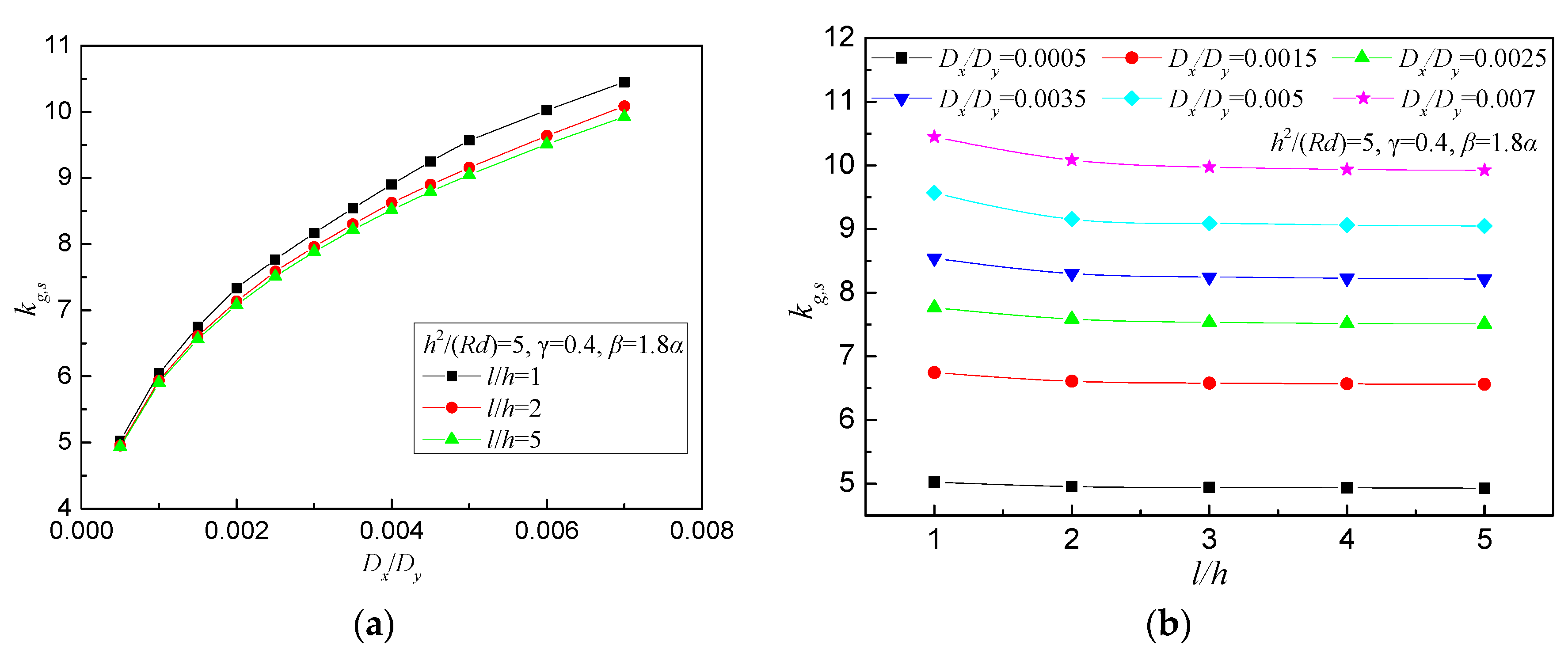
Figure 3 shows the effect of the rigidity ratio
Dx/
Dy and the length to height ratio
l/h on the global shear buckling coefficient
kg,s for a four-edge simple support. As we can see from
Figure 3, the global shear buckling coefficient
kg,s increases with the increase of the rigidity ratio
Dx/
Dy and decreases with the increase of the length to height ratio
l/
h but only very little. When
l/
h is larger than 2, which is common for bridges, the change of
kg,s is minimal and the values of
kg,s show a converging trend. The conclusion remains unchanged when changing the values of
h2/(
Rd),
γ, and the boundary conditions. Because the values of
kg show a converging trend when
l/
h is larger than 2, assuming
l/
h = 5 for further calculation will not only ensure the accuracy of the calculation but also meet the engineering requirements of design simplicity.
3. Influence of γ on the global shear buckling coefficient kg
Table 3 lists the values of
kg,s for
γ equal to 0.38, 0.4, 0.42 and 0.44 respectively when
l/h = 5,
h2/(
Rd) = 5 and
β = 1.8
α for the four-edge simple support. The results are practically equal for
γ equal to 0.38, 0.4, 0.42 and 0.44. The conclusion remains unchanged when changing the values of
l/h,
h2/(
Rd), and the boundary conditions. This implies that the modulus ratio
γ has little effect on the coefficient
kg for common HCG bridges with CSWs. In what follows, assuming
γ = 0.4 will not only ensure the accuracy of the calculation but also reduce the number of parameters in the parametric study.
4. Influence of h2/(Rd) on the global shear buckling coefficient kg
Table 4,
Table 5 and
Table 6 lists the values of
kg for various values of
h2/(
Rd) and
Dx/
Dy when
l/h = 5,
γ = 0.4 and
β = 1.8
α for three boundary conditions.
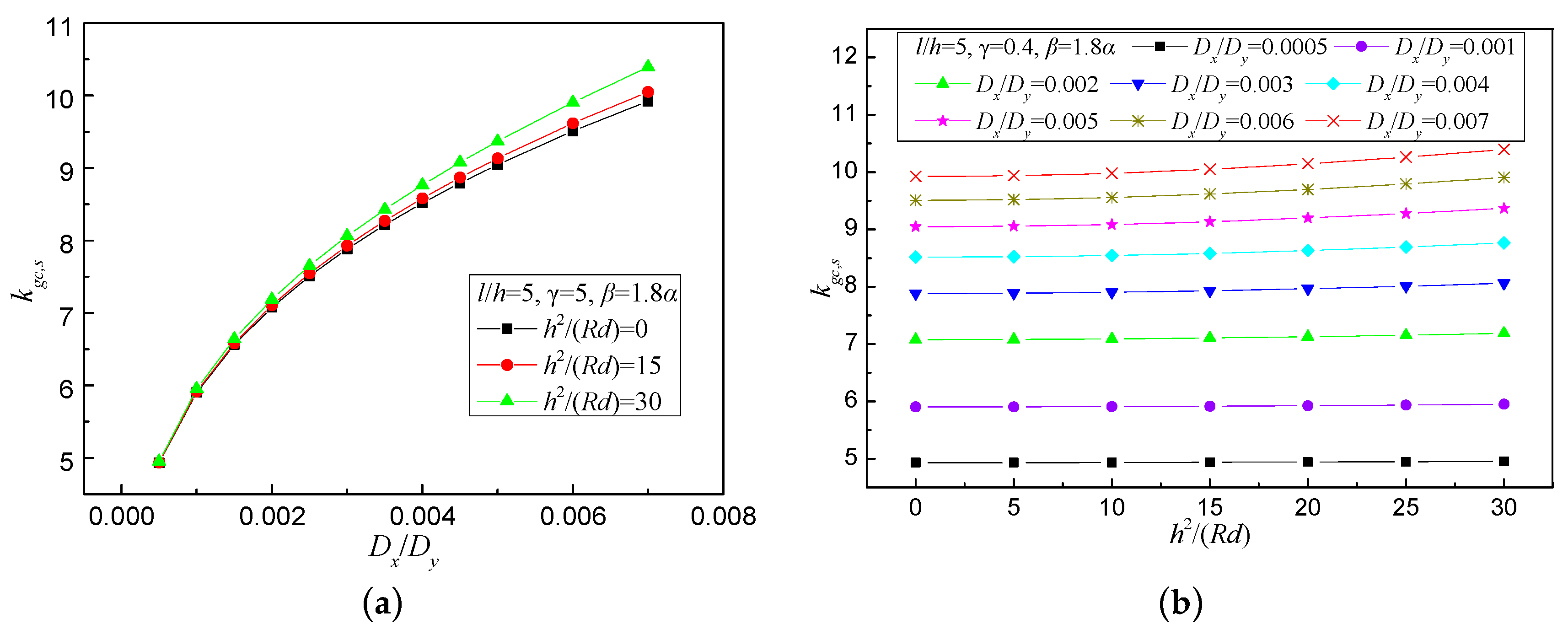
Figure 4 shows the effect of
h2/(
Rd) and
Dx/
Dy on the global shear buckling coefficient
kg,s for the four-edge simple support. As we can see from
Figure 4 and
Table 4,
Table 5 and
Table 6, the global shear buckling coefficient
kg increases with the increase of the rigidity ratio
Dx/
Dy and increases slightly with the parameter
h2/(
Rd). This implies that the global shear buckling stress of curved bridge webs is slightly higher than that of straight bridge webs. For HCG bridges with
Dx/
Dy ≤ 0.007 and
h2/(
Rd) ≤ 20, the global shear buckling stress of curved bridge webs can be calculated conservatively as that of straight bridge webs with a difference less than 2.5%.
The first row of data for
h2/(
Rd) = 0 in
Table 4,
Table 5 and
Table 6 represents the global shear buckling coefficient of CSWs for straight girders. Through fitting of the first-row data in
Table 4,
Table 5 and
Table 6, for CSWs with 0.0005 ≤
α ≤ 0.007, the global shear buckling coefficients
kg,s,
kg,f,
kg,fs for straight girders can be estimated respectively by Equations (19) and (20).
For a four-edge simple support:
For a four-edge fixed support, or for two edges constrained by flanges fixed and the other two edges simply supported:
For trapezoidal CSWs that are commonly used in actual bridges, the rigidity ratio α can be expressed as Equation (21).
It is worth mentioning that the formulas for the global shear buckling stress
(Equation (18)) and the global shear buckling coefficient
kg (Equations (19) and (20)) proposed in this paper are slightly different from these proposed by previous researchers [
8]. This is due to the fact that while previous researchers derived the formula for the global shear buckling stress
the complete CSW was treated as an orthotropic plate with its length much larger than its width, and using a simplified deflection function, which is different from the function used in this paper.


