1. Introduction
The past century has been characterized by rapid advances in materials development, especially in functional materials, such as piezoceramic materials. Nowadays, on one hand, piezoceramic materials have found a wide spectrum of commercial applications [
1,
2], such as ultrasonic measurement [
3,
4,
5], vibration sensing and control [
6,
7,
8], force sensing [
9,
10], pumping and dosing [
11,
12,
13], ultrasonic cleaner, ultrasonic welding, energy harvesting [
14,
15] and imaging [
16], among others. On the other hand, piezoceramic materials and devices are still being actively researched to achieve better performance with lower cost and less environmental impact [
17,
18,
19].
One of the actively researched piezoceramic devices is the atomizer, which utilizes a piezoceramic actuator to convert liquid to atomized particles through high frequency ultrasonic vibration; it can cause ultrafine droplet atomization. Ultrafine droplet atomization is widely applied in combustion with liquid fuel [
20], inhalation therapy [
21,
22,
23], printed circuits [
24], three-dimensional (3D) prototyping [
25], precise surface coating [
26,
27], spray drying [
28], spray cooling [
29,
30], and inkjet printing [
31], among other fields. Ultrafine droplet atomization has high important application potential, and scholars began to focus on atomization devices.
Kuttruff first provided a detailed explanation of the actuating principle of a surface acoustic wave atomizer [
32]. Berggrend et al. designed an extrusion-type piezoceramic ultrasonic atomizer that produced droplets with an average diameter of 27 μm [
33]. The working mechanism of this type of atomizer is to release energy to the entire liquid system to break the surface tension of the liquid and allow the droplets to escape from the surface for atomization and ejection. The atomization is formed at the surface of the liquid. However, the energy is applied to the entire liquid system.
Heij et al. proposed a stationary vibrating mesh atomizer driven by piezoelectricity to improve energy use, minimize the droplet size range and strengthen control over the atomization process [
34]. To further minimize the droplet size range, Pan et al. designed a new type of stationary micro-cone hole driven by piezoelectricity [
35]. In this type of atomizer, the pressure inside the liquid chamber is modulated by the vibration of a piezoelectric vibrator, and the liquid is ejected from the micro-jet hole when the pressure inside the liquid chamber is sufficiently large, resulting in atomization. In designing this type of atomizer, it is necessary to add an atomizer chamber with variable volume. The structure of this type of atomizer is complex, which limits the miniaturization of the atomizer.
In this research, the micro-cone hole is machined within the plate metals of the vibrating mesh atomizer. There is no liquid chamber with variable volume in the process of atomization, the structure of the atomizer is simplified, and the atomization process can be controlled. Maehara et al. proposed the atomizer with this structure [
36,
37]. Lu et al. designed an efficient cooling device that used a vibrating mesh atomizer [
38,
39]. This type of atomizer can effectively improve energy use and minimize the droplet size range. It also has the advantages of portability and straightforward integration, resulting in a revolutionary influence on combustion with liquid fuel [
40,
41].
We previously determined that the micro-cone hole of the vibrating micro-porous atomizer has an important influence on the atomization effect, particularly the dynamic change of the cone angle of the atomizer under the working conditions. Therefore, this study was designed to verify the dynamic change of the micro-cone angle and its effect on the atomization effect of the vibrating mesh atomizer.
3. Theoretical Analysis
3.1. Analysis of the Flow of Liquids
Under the excitation of alternating current AC signal, PZT will produce vibration, which will drive the disperser vibration. The effects of gravity on the fluid are assumed to be negligible. In this case, the pressure in the aperture varies with volume. When the metal sheet is compressed, the volume of the micro-cone hole decreases and the liquid pressure increases in turn; however, when the metal sheet is stretched, the volume of the micro-cone hole increases and the liquid pressure decreases in turn.
The fluid in the micro-cone hole has two external environments: one is the liquid chamber, and the other is the atmosphere. During atomization, the small side of the micro-cone hole is in contact with the atmosphere, and the other side is in contact with the liquid. When the volume on the upper side decreases, the cone angle increases, and the pressure in the upper side of the micro-cone hole also increases. Liquid flows from regions of high pressure to the regions of low pressure. One branch of fluid flows into the space below the neutral layer and fills the space where the volume in the micro-cone hole becomes larger, and the other part of the fluid extrudes into the outer space with lower pressure. The low pressure at the lower side causes the liquid to flow into that side, into a region where liquid is accumulated from flows from the upper side and from the liquid chamber. When the volume on the upper side increases, the cone angle decreases. The direction of the liquid flow will be opposite.
3.2. Analysis of the Flow Resistance
The vague phrases “one branch” and “the other branch” are used above because the fundamental flow constraints include not only the pressure generated by the volume changes of the aperture but also the inertial force and the capillary force. A slight volume change in the liquid chamber beneath the dispenser also causes both atomization and ejection directly. In the tapered aperture, the flow resistance in the diffuser element is different from the flow resistance in the nozzle element.
In a single cycle, the micro-cone hole acts as a nozzle/diffuser element. The difference between the two flow resistances determines the flow rates of “one branch” and “the other branch” described above and allows one-way flows from the flared (the larger diameter of the micro-cone hole) side to the tapered side (the smaller diameter of the micro-cone hole).
The atomizer uses AC voltage. Therefore, the angle of the micro-cone hole changes constantly. The flow resistance of the diffuser and nozzle also changes constantly. At a certain moment, ξ(t)Dd is the diffuser element loss coefficient, and ξ(t)Dn is the nozzle element loss coefficient.
Therefore, in one cycle, the average of the diffuser element loss coefficient is:
where
T is the length of one cycle.
Similarly, the average of the nozzle element loss coefficient is:
where
T is the length of one cycle.
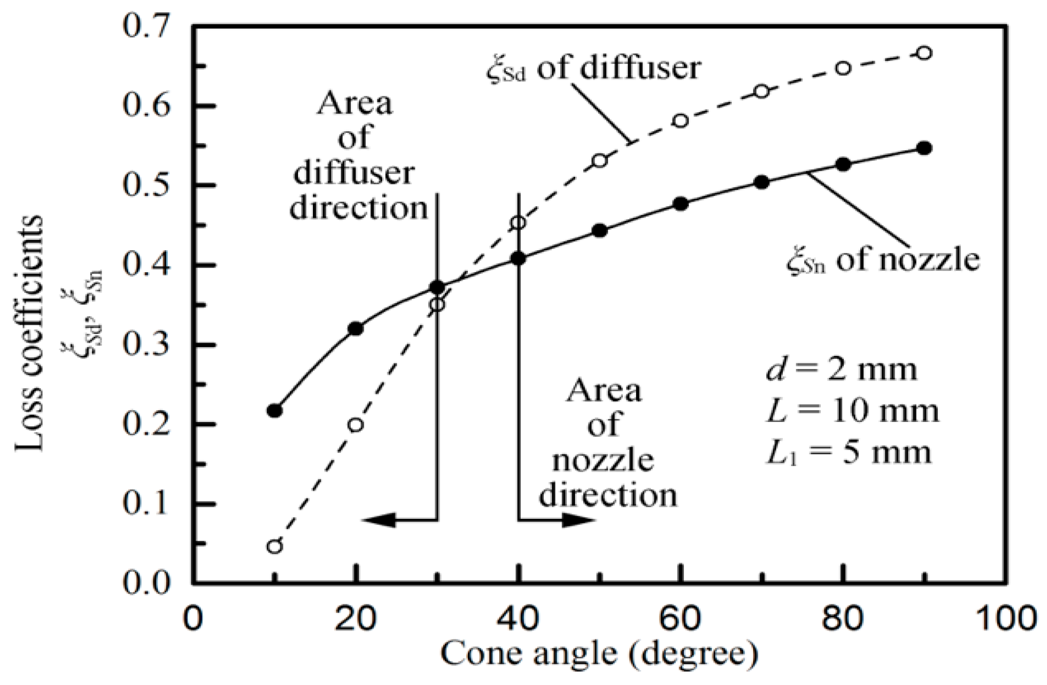
Figure 4 shows the empirical curves of the cone angle, the diffuser loss coefficient ξ
Sd, and the nozzle loss coefficient ξ
Sn [
44]. The flow resistance is also a function of the cone angle on a macroscopic level (only cone angles of more than 40° are discussed here). The flow resistance is higher in the diffuser element than in the nozzle element when the cone angle is more than approximately 30° [
44]. The flow resistance increases as the angle increases.
Olsson [
45] compared the results obtained from the numerical calculation for conical flows and those mentioned in reference [
46] and found that the flow resistances in the nozzle/diffuser elements at the micro-scale are similar to those at the macro-scale. Therefore, in this study, the flow resistances in the nozzle/diffuser elements at the micro-cone hole can use the empirical curves in
Figure 4. From this figure, the diffuser/nozzle loss factors are as follows: ξ
Sn = 0.49, ξ
Sd = 0.62.
3.3. Atomization Rate
In a previous study [
42], it was found that when the piezoelectric vibrator moves from the equilibrium position to the extreme position, the volume of the liquid chamber changes is follows:
where Δ
VVS is the volume of the liquid chamber changes.
The volume of the cone apertures changes is follows [
42]:
where Δ
VVD is the volume of the cone apertures changes.
Zhang et al. provided an equation for the net volume flow rate when the cone hole is in a steady state [
44]:
where Δ
V is the volume variation of the liquid chamber,
f is the vibrational frequency,
ξNd is the diffuser element loss coefficient, and
ξNn is the nozzle element loss coefficient.
Therefore, the flow rate caused by the change of the volume of the liquid cavity is:
where Δ
VS is the volume variation caused by the piezoelectric vibrator.
Similarly, the flow rate caused by the change of the volume of the micro-cone hole is:
where ΔV
D is the volume variation caused by the micro-cone hole.
With the tapered side exposed to the air and the flared side immersed in the liquid, the overall volume flow of the dispenser is:
When the atomizer shown in
Figure 1a is reversed by 180°, the flared side is exposed to the air, and the tapered side immersed in the liquid. The pumping effect of the micro-cone hole and liquid chamber can also cause atomization. However, in such a case, the flow resistance is higher in the diffuser element than in the nozzle element, and the atomization rate is much less than that it is in normal conditions.
Due to the difference of the diffuser flow resistance and the nozzle flow resistance, and the volume changes in the micro-tapered aperture and the liquid chamber, a pumping effect is produced, and the one-way flow of the liquid is caused by the pumping effect.
3.4. The Droplet Formation Process
Figure 5 shows the modeling of the droplet formation process in one cycle. It can be seen from the figure that when the pressure in the micro-cone hole is positive, the liquid in the cone hole flows outward to form a liquid column; when the pressure in the cone hole is negative, the liquid droplets will continue to flow outward for a period of time due to inertia; with the continuous negative pressure in the micro-cone hole, the liquid column begins to flow back into the hole, then the liquid begins to move along the inner wall of the cone hole to the hole, and the liquid part in the hole. Gradually fined and then fractured to form atomized droplets. It can be found from the figure that the outflow liquid flows outward at the center faster than the liquid near the outlet, so when the liquid at the outlet begins to move into the hole, the outermost liquid still keeps flowing outward, which makes the droplet appear as thinning neck near the outlet, thus creating conditions for liquid fracture.
4. Design of Experiments
In the experiment, we plan to measure atomization rate, atomization height and the particle size of the atomized particles. Atomization rate is the liquid quality of the atomizer per minute. Atomization height is the maximum height of the atomized droplets by hole injection. The particle size of the atomized particles is the mean diameter of the atomized particles. The liquid used in the experiment was water, which had a temperature of 20 °C and a kinematic viscosity of 1 × 10⁻³ Pa·s.
Figure 6 shows the photograph of measuring the vibration mode of the piezoelectric vibrator. The velocity and amplitude curves of the atomized tablets were obtained using a Polytech PSV-300F-B laser vibrometer. The resonance frequency was obtained from the curve, and the resonance point was determined. In addition, the atomization rate was measured at each resonance point at an operating voltage of 40 V.
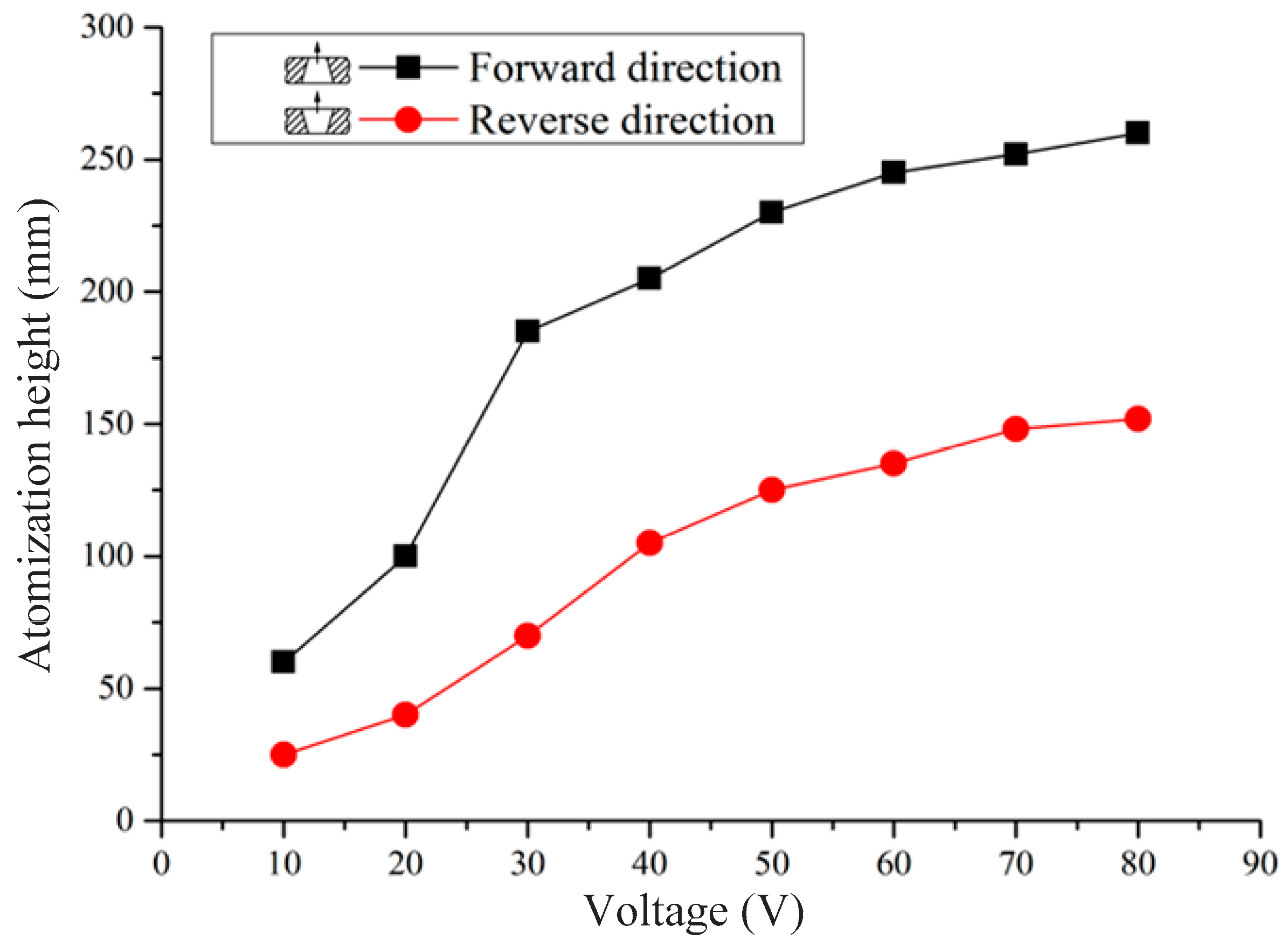
In the previous experiment, we obtained the optimum operating frequency of the atomizer. To validate the effect of the micro-cone hole on atomization performance, the atomization rates and the atomization heights are measured at both the flared (forward direction) and tapered sides (reverse direction) with different working voltages at the optimum operating frequency.
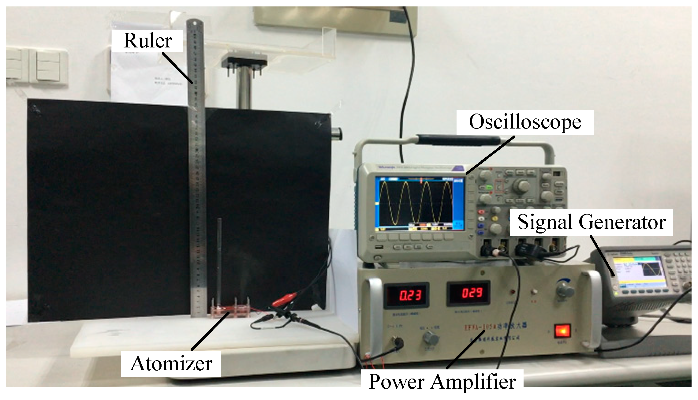
Figure 7 shows the measurement of the atomization rate and the atomization height. The atomization rate can be obtained by electronic weighing, and the atomization height can be directly investigated using a straight ruler.
To further validate the effect of the change of cone angle of on atomization performance, the particle size of the atomized particles was measured at different applied voltages at the optimum operating frequency.
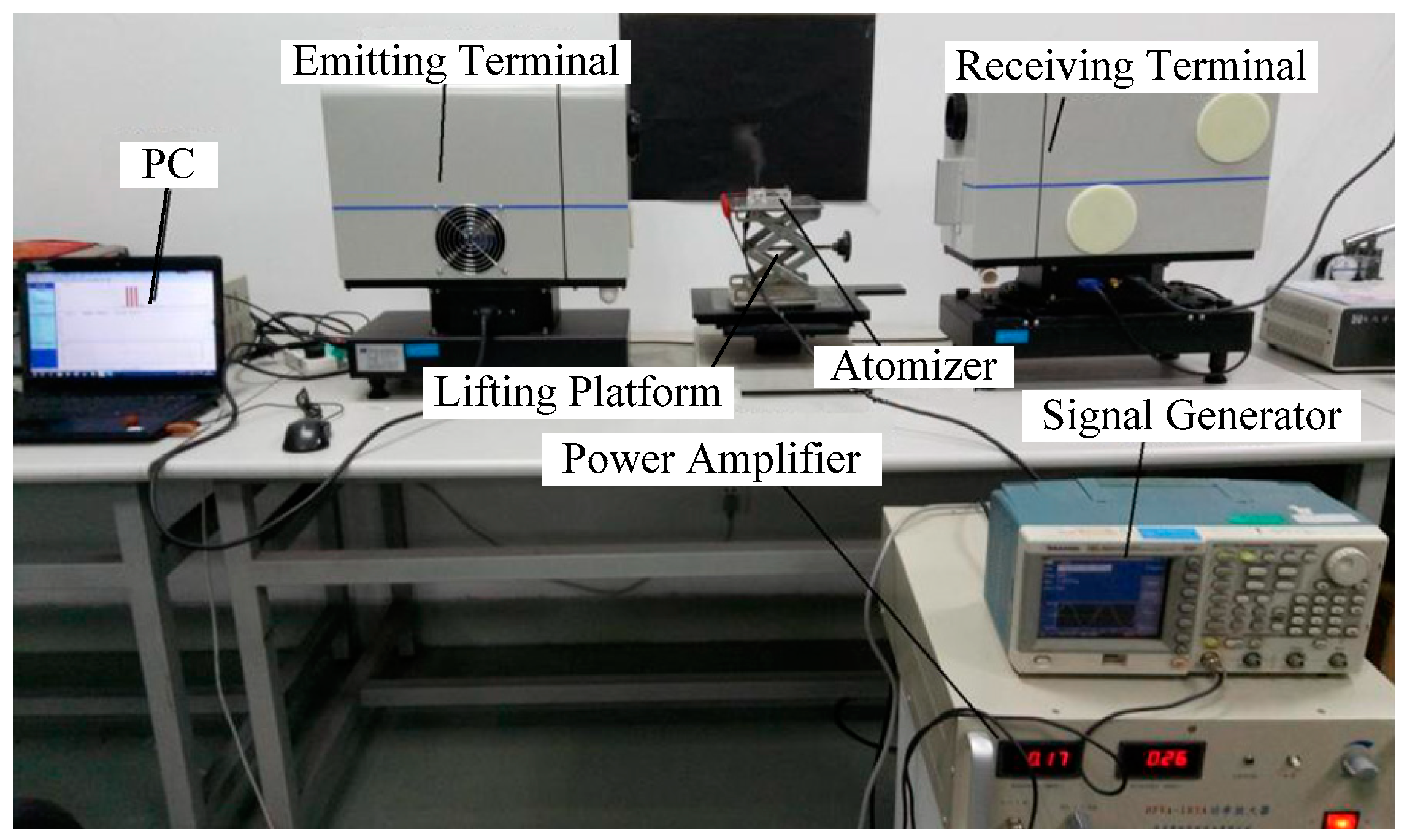
Figure 8 shows the measurement of the particle size of the atomized particles.
The relationship among the atomization rate, the atomization height, the particle size of the atomized particles and driving voltage is obtained from the above test. To establish the relationship between the cone angle and the driving voltage, different DC voltages were applied to the piezoceramics actuator, and the changes in the micro-cone hole were observed using microscopy.
Figure 9 shows the method for measurement of the hole. The method for measuring the cone hole’s diameter is as follows: firstly, we used three points to plot the diameters of a circle (the circle is plotted according to the outermost of the hole). In the measurement, the localization of the three points is hand chosen. In order to avoid the influence of subjective factors on the measurement results, we chose three conspicuous points to plot the circle. We continued to search for these three points after the voltage changed, and used these three points to plot the diameters of a circle. Then, we obtain the diameter of the cone hole under different voltages. In the measurement, we let the tapered side of the dispenser face upward firstly, and use the above method to measure the tapered side diameter of the micro-cone hole under DC voltage (the DC voltages are −125 V, 0 V, 125 V, 250 V and 125 V, respectively), and record the results of the measurements for the five voltages. The change of the large aperture in the micro-cone hole can be measured by the same method. The thickness of the dispenser can be measured by vernier calipers, and the angle of the micro-cone hole can be obtained from the geometric relations.
5. Results and Discussion
Figure 10 shows the frequency sweep curves of the vibration velocity and amplitude, vibration modes of resonance points, deformation diagram of the piezoelectric oscillator and atomization rates at the resonance points. In this experiment, the flared end of the atomizer is attached to the water tank and is placed in contact with the fluid surface (i.e., in the forward direction).
In this experiment, no visible atomization was observed below a resonant frequency of 15.9 kHz.
As shown in
Figure 10, the atomization rate increased gradually with resonance frequency and at the resonance frequency of 121.1 kHz, the atomization rate was maximized (2.805 mL/min). However, at the resonance frequency of 148.3 kHz, the atomization rate decreased significantly.
When the frequency increases (where ① refers to the increasing frequency trend), the dispenser deformation becomes more complex, which indicates that its rate of deformation curvature change and the rate of tapered aperture volume change both increase. Furthermore, the rate of liquid chamber volume change decreases (where ② refers to the decreasing rate of liquid chamber volume change trend). However, the atomization rates at the resonant frequencies generally increase incrementally. This finding contradicts the findings of previous discussions on the pumping effect caused by volume changes and the atomization generated under ultrasound conditions. No clear explanations are given in the literature [
29,
38,
39].
When the rate of dispenser deformation curvature change increases (referring to larger changes in the dynamic cone angle) as shown in
Figure 3, the dynamic cone angle pumping effect becomes stronger, and this results in an increase in the atomization rate. Therefore, the vibration and the elastic deformation of the dispenser allow the micro-dynamic cone angle to act as a pump. There are two possible reasons for the reduction of the atomization rate at the sixth-order resonance point. The first is that the overall displacement amplitude decreases at higher resonance modes and the rate of change also decreases. The second reason is that the flow velocity in the aperture increases with increasing frequency, and this leads to the increased flow resistance. Therefore, the dynamic cone angle plays an important role in the atomization.
Figure 11 and
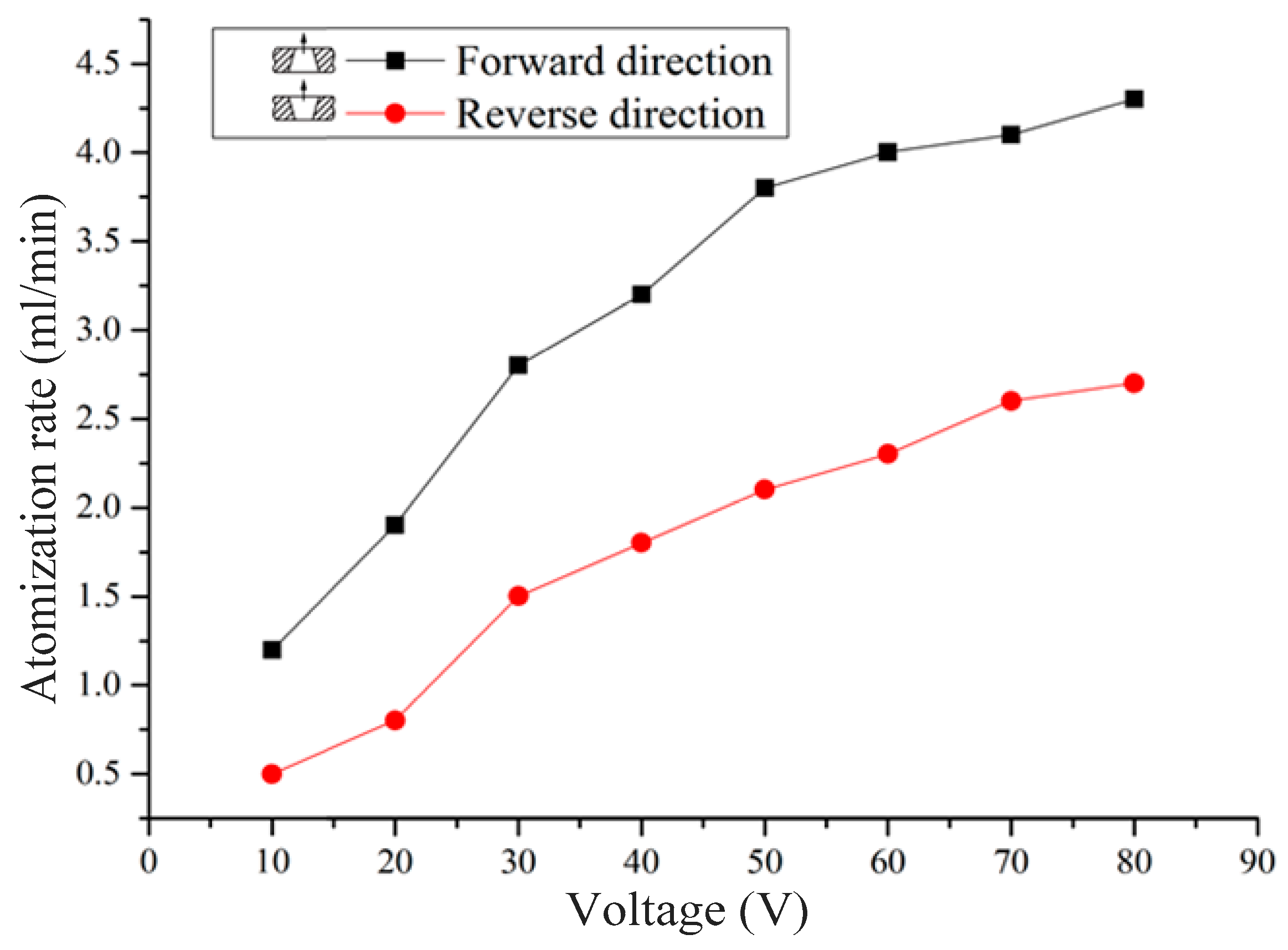
Figure 12 show that the atomization rate and atomization height measured in the forward direction are much higher than those measured in the reverse direction. This atomization rate and atomization height difference increases as the working voltage increases. As determined through the analysis above, the atomization of the vibrating mesh atomizer is caused by pressure atomization and dynamic cone angle atomization. The pressure atomization is caused by the change of the volume in the liquid chamber, and the dynamic cone angle atomization is caused by the change of the volume in the micro-cone hole. When the vibrating mesh atomizer is working in the forward configuration, the atomization rate is the sum of the pressure atomization and the dynamic cone angle atomization, as shown in Equation (8). Therefore, the atomization rate in the forward direction is much higher than in the reverse direction. The initial velocity of the atomized droplets is more rapid at the exit of the micro-cone hole when the atomization rate is larger. Therefore, the atomization height in the forward direction is much higher than in the reverse direction. The experiment shows that the micro-cone hole is integral to and influences the atomization behavior.
Figure 11 and
Figure 12 show that at the same resonance frequency, with increasing driving voltage, the atomization rate and the atomization height gradually increase. When the driving frequency is unchanged, the vibration mode of the piezoelectric vibrator is also unchanged. With increasing driving voltage of the piezoelectric vibrator, the deformation of the piezoelectric vibrator amplitude is greater. Xu et al. proposed that the flow is driven by the actual displacement of the piezoelectric in a piezoelectric nozzle [
47], and the liquid obtained more energy when the voltage increased. With increasing driving voltage of the piezoelectric vibrator, the deformation of the piezoelectric vibrator amplitude is greater, and the angle and change of the volume of the micro-cone hole increases. The difference of the average flow resistance in the forward and reverse directions increases with an increase in the angle of the micro-cone hole. With the increase of the displacement of the piezoelectric vibrator, the increase of volume of the micro-cone hole and the increase of the difference of the average flow resistance in the forward and reverse directions, the atomization rate and atomization height also increase.
Figure 13 and
Figure 14 show that at the same resonance frequency, with increasing driving voltage, the atomization particle size decreases, the atomized particle size distribution is more concentrated, and droplet size range gradually decreases. When the driving frequency is unchanged, the vibration mode of the piezoelectric vibrator is also unchanged. With increasing driving voltage of the piezoelectric vibrator, the deformation of the piezoelectric vibrator amplitude is greater, and the angle and change of the volume of the micro-cone hole increases. As shown in
Figure 3, the diameter of the tapered side with the micro-cone hole is smaller when the piezoelectric vibrator is in the lowest position. By analyzing the theory of the phenomenon of dynamic cone angle [
42,
43], the atomized droplets are found to eject from the micro-cone hole into the air when the piezoelectric vibrator reaches the lowest position. The diameter of the atomized particles is reduced by reducing the diameter of the tapered side with the micro-cone hole in this position. Simultaneously, the maximum diameter of the atomized droplets is reduced by reducing the diameter of the tapered side with the micro-cone hole. The speed of droplets leaving the micro-cone hole increases with the increase of voltage. The distance between the two separated droplets increases with the increase of speed. At this point, the probability of collision decreases, and the atomized particle size distribution is more concentrated. The experiment to characterize the atomization parameters at different driving voltages proves the presence of the dynamic cone angle, and the experiment establishes that the dynamic cone angle affects the atomization performance.
Figure 15 shows the results of measurement of the parameters of the micro-cone hole at different voltages along with schematics of the change.
Figure 15a–e shows the results of five time measurements at different voltages.
Figure 15 shows that the micro-cone hole changes constantly under diverse voltages.
Table 1 shows the measurement results of the micro-cone hole under different voltages. It can be seen from
Table 1 that the angle of the micro-cone hole changed under different working voltages.
The angle of the micro-cone hole can be closely related to the voltage through microscope observation. The previous experiment showed that the atomization performance is affected by the driving voltage. Therefore, the atomization performance is closely related to the change of the angle of the micro-cone hole.
It is also important to note that in this experiment, the voltage applied is DC voltage, and in the actual work process, the voltage applied to the nebulizer will be AC voltage. The frequency of the applied alternating current is consistent with the resonant frequency of piezoelectric, thus producing resonance and augmenting the vibration of the piezoelectric vibrator. Thus, the actual deformation of the dispenser is much more complicated than that in the present experiment, and these resulting changes in the angle will also be larger than those in the experiment.
6. Conclusions
Liquid fuel can be atomized by piezoceramic atomizers, which will ensure that the combustion is more complete and thorough to reduce the pollution. Our research team studied the micro-cone hole atomizer. The main conclusions are summarized as follows:
The phenomenon of dynamic cone angle is analyzed in this study. Under micro-scale conditions, when an outside force or vibration is applied to the aperture, the resulting periodic elastic deformation allows the aperture to become smaller and then larger in a cyclical manner, which results in periodic changes in the aperture volume at the micro-scale level, with the change of the angle of the micro-cone hole increasing with increasing driving voltage.
The phenomenon of the dynamic cone angle inside the vibrating mesh atomizer is analyzed. Because of the difference between the diffuser flow resistance and nozzle flow resistance, the one-way flow of the liquid produced by the volume change of the micro-cone hole and the liquid chamber causes atomization.
The experiments reveal that the atomization rate and the atomization height are different when the vibrating mesh atomizer is working in the forward and reverse directions. The atomization rate and the atomization height measured in the forward direction are much higher than that measured in the reverse direction. The atomization rate and the atomization height increased with driving voltage, and the diameter of the atomized particles decreases with increased driving voltage.
The experiment shows that the micro-cone hole of the vibrating mesh atomizer has an important influence on the atomization effect, particularly the dynamic change of the cone angle of the atomizer under the working conditions.


