Featured Application
The work uses depth image to guide the artifact handling process, which can be applied in view synthesis for 3D video and free viewpoint video (FVV).
Abstract
The depth image based rendering (DIBR) is a popular technology for 3D video and free viewpoint video (FVV) synthesis, by which numerous virtual views can be generated from a single reference view and its depth image. However, some artifacts are produced in the DIBR process and reduce the visual quality of virtual view. Due to the diversity of artifacts, effectively handling them becomes a challenging task. In this paper, an artifact handling method based on depth image is proposed. The reference image and its depth image are extended to fill the holes that belong to the out-of-field regions. A depth image preprocessing method is applied to project the ghosts to their correct place. The 3D warping process is optimized by an adaptive one-to-four method to deal with the cracks and pixel overlapping. For disocclusions, we calculate depth and background terms of the filling priority based on depth information. The search for the best matching patch is performed simultaneously in the reference image and the virtual image. Moreover, adaptive patch size is used in all hole-filling processes. Experimental results demonstrate the effectiveness of the proposed method, which has better performance compared with previous methods in subjective and objective evaluation.
1. Introduction
With the development of computer technology, 3D video has become increasingly popular recently. It provides users with a more authentic and interactive viewing experience [1]. Free viewpoint video (FVV) has also drawn a lot of attention as it allows users to choose the viewpoint freely [2]. However, for FVV, it is unrealistic to obtain the video of arbitrary viewpoint through a series of cameras in practical application. Due to bandwidth limitations, only a certain number of viewpoints can be transmitted. How to generate high-quality FVV based on a limited number of viewpoints has become one of the research hotspots in the field of 3D video [3]. One practical way is to create virtual views on the receiving end. In this context, depth image based rendering (DIBR) is a better choice [4]. Depth image is usually represented by a single-channel grayscale image, which takes up less storage space than a 24-bit color image of the same size. Depth image encoding is more efficient than that of color image [5]. As discussed in Reference [4], the bit rate of depth image requires below 20% of the basic color image bit rate. Therefore, depth image requires less bandwidth than color image, which can speed up the video transmission. The core process of DIBR technology is 3D warping. As shown in Figure 1, it consists of two steps. First, all pixels in the reference image are re-projected into the world coordinate system according to the depth information. These points are then projected into the image plane of the virtual view based on the virtual camera parameters [6].
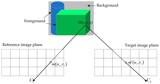
Figure 1.
Schematic diagram of 3D warping.
In the 3D warping process, due to inaccurate depth values and occlusion relationship between objects, some artifacts appear in the synthesized virtual view, such as cracks, ghosts, holes and pixel overlapping [7]. Cracks are caused by the rounding errors of the float results, usually 1–2 pixels wide. Ghosts mean that pixels at the boundary of foreground are incorrectly projected into the virtual view as background pixels. The foreground and background textures are mixed due to errors of depth values. As a result of the positional relationship between the reference view and the virtual view, adjacent pixels with different depth values in the reference image will not be contiguous in the virtual view, which leads to two situations. One is the overlap of pixels, which will affect the occlusion relationship between objects in the virtual image if not processed. The other is that the region occluded by the foreground is exposed in the virtual view, resulting in a large hole called disocclusion. In addition, there is another type of hole that usually appears at the border of the virtual image. They are outside the imaging range of the reference view and are known as out-of-field regions (OFRs).
In order to prevent artifacts and improve the quality of virtual view, in this paper, we propose a novel view synthesis method based on the DIBR process. First, a virtual image is generated by the original DIBR. The hole pixels at the boundary are marked and inversely projected into the reference view to calculate the extended region of the reference image and its depth image. The extended region is filled with pixels from the nearby source region, aiming to fill the OFRs in the virtual image. Second, unidirectional depth image preprocessing is applied to detect and remove the ghosts. In addition, the 3D warping process is modified to avoid cracks and pixel overlapping. Finally, a local background-first inpainting method is proposed to fill the disocclusions. This approach can prevent the penetration of the foreground objects. The rest of the paper is organized as follows. The related previous algorithms are discussed in Section 2. The proposed framework is presented in Section 3. Experimental results are provided in Section 4. Finally, the conclusions are given in Section 5.
2. Related Work
In the 3D warping process, accurate depth value is important for the quality of the virtual image. Due to the precision limitations of stereo matching algorithm and depth camera, the depth image may be coarse. Therefore, many algorithms preprocess the depth image before DIBR, aiming to smooth the depth value inside the object and reduce the dramatical depth change along the boundary between foreground and background. Zhang et al. [8] propose a symmetric gaussian filter to smooth the depth image. An asymmetric filter is employed to reduce the holes in Reference [9]. In these methods, the regions that do not cause artifacts are also filtered, resulting in degradation of the virtual image quality and increased computational complexity. Chen et al. [10] use an edge-dependent gaussian filter to overcome this problem. The geometric distortion of non-hole regions in the virtual view is avoided while horizontal edge is smoothed. In Reference [11], only the background region in the depth image is smoothed, so the foreground object can be protected. These filters can prevent small holes and cracks, but they are not suitable for large baseline and disocclusions. Lei et al. [12] use the linear interpolation to modify the depth value of the background pixel, which is adjacent to the foreground object. The decrement of the depth value from the foreground to the background causes the disocclusion to be divided into several small holes, which are easily filled by the image inpainting. This method is suitable for large distance between foreground objects and a simple background. For complex background, the partition of disocclusion may cause distortion, which reduces the quality of virtual view. Liu et al. [13] propose a structure-aided domain transform smoothing method to process the depth image. This method builds a framework in the transformed domain to reduce computational complexity. However, due to the loss of depth details on the foreground edge, the boundary between the foreground and the background object in the synthesized image may become blurred.
Currently, there are two types of methods to solve the large disocclusion problems. One is to use the spatial correlation to fill the disocclusion. Criminisi et al. [14] propose a classical exemplar-based inpainting method. The priority of the pixels at the boundary of holes are calculated first, then the best matching patch is searched from the source region and copied to the hole which has greatest priority. For this method, foreground textures can be sampled to fill the disocclusion. This is not appropriate because the disocclusion comes from the background region. In order to solve this problem, some improved inpainting methods based on depth information are proposed. Daribo et al. [15] introduce the depth value into the priority calculation and best matching patch searching. The patch with lower depth variance is given higher priority and filled by the patch in the source region, which has similar depth levels and colors. Oliveira et al. [16] replace the data term with the depth term, which prioritizes the greatest depth values. Kao [17] proposes a depth-based gray-level distance to measure the similarity between the two patches. In addition, Luo et al. [18] propose a fast Markov random field-based method to formulate the hole filling as energy optimization problems and use loopy belief propagation (LBP) to solve them. The distance transform technique is used to compute the message for LBP so that the computational cost can be reduced. For these methods, if there is an error of the foreground object boundary in depth image, ghost will appear that can affect the computation of priority and cause the spread of wrong texture. A foreground removal approach is proposed in Reference [19]. The foreground objects are removed from the reference image and depth image, and then the removed regions are filled by a modified Criminisi’s inpainting algorithm. The constructed background image is applied to fill the disocclusions in the virtual image. Han et al. [20] use foreground object extraction to segment the reference image into multiple layers. Global disparity adjustments and local depth control are performed in each layer so that the visual discomfort is alleviated. However, accurate separation of foreground and background objects is difficult, especially for the situation that the foreground and background contain multiple depth levels. Furthermore, the OFRs are not all belong to backgrounds and should not be filled by the same priority computation as the dis-occluded regions. The other type of methods is to handle the disocclusion in temporal domain. For 3D video and FVV, the region occluded by the foreground objects in the current frame may become visible in other frames [21,22]. Sun et al. [23] propose an online background model construction method based on switchable Gaussian model (SGM), which improves the adaptability to the scene. Deng et al. [24] establish an adaptive background model based on the Gaussian mixture model (GMM) to fill the dis-occluded regions. However, for a single reference image and still foreground objects, the occluded backgrounds in the scene may not be fully obtained, so it is difficult to establish a good background model in these situations.
Furthermore, when virtual view is generated using multiple reference views, view blending is an effective method to filling the disocclusions [25,26,27]. Li et al. [28] point out that using two or more neighboring reference views can greatly reduce the holes in the virtual view. This is because the background region, which is not visible in the left reference view may be visible in the right reference view, so the hole-filling results can be very accurate. Deng et al. [24] also use two reference views in their method, and obtain the virtual view through a weighted view blending process. However, multi-view rendering requires more devices and transmission bandwidth compared to single view rendering. In Reference [29], a real-time DIBR system that consists of disparity estimation and view synthesis is proposed. It applies different methods to handle the holes for view interpolation and extrapolation. Moreover, the system is implemented on FPGA to achieve a high processing speed. In order to reduce the computational cost, holes in the OFRs are considered as background regions in the filling process. For the virtual view outside the baseline, view blending can only reduce a limited number of holes. Therefore, the research on single view rendering method is still required.
In this paper, a single reference image and its depth image are used for the synthesis of virtual image. We apply different methods to handling the artifacts based on their natures. The OFRs are filled with the extended reference image and depth image. This process will focus on maintaining the local consistency of the texture rather than just filling the holes with background pixels. Ghosts are removed in the depth image preprocessing and mapped to the correct position. In the modified 3D warping process, cracks are filled and all pixels in the virtual image maintain the proper occlusion relationship. Disoccluded regions are filled from the local background side first. The source regions are not only limited to the virtual image, but also contain the regions which have similar depth values in the reference image. Since an image contains different edge structures and texture features, an adaptive patch size based on gradient information is applied to the image inpainting approach.
3. Proposed Framework
In this section, the proposed method will be described in detail. The block diagram of the proposed framework is illustrated in Figure 2. The input reference view is optimized before the DIBR process to prevent errors in depth acquisition and extend the imaging range. During view synthesis, the occlusion relationship between objects is maintained. Our work mainly includes four parts: Reference view extension, depth image preprocessing, modified 3D warping, and disocclusions filling.
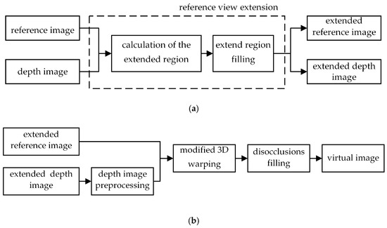
Figure 2.
Framework of the proposed method: (a) Illustration of reference view extension; (b) The flow chart of proposed artifact handling approach using depth information.
3.1. Reference View Extension
For view synthesis, the virtual viewpoint has a rotation and translation relationship with the reference viewpoint, as shown in Figure 3. In Figure 3a, the virtual view has only horizontal translation relative to the reference view, while the rotation and translation between the two views are both included in Figure 3b. Assume that the intrinsic matrix of the virtual camera is the same as the reference camera. It can be seen in Figure 3, as the virtual view moves, its imaging range will exceed the reference view. No pixels in the reference image are projected into these areas, so that holes will be created, i.e., OFRs. OFRs are not caused by the occlusion between the foreground and background, so it is difficult to confirm whether these regions belong to the background, especially for the depth image with multiple depth levels. Most of the previous methods use background pixels to fill the OFRs together with disocclusions, which is not suitable and easy to make the inconsistent content to be selected. In this paper, different inpainting methods based on Criminisi’s algorithm are used to fill the OFRs and disocclusions. To deal with the OFRs, we extend the reference image and depth image. Pixels in the neighbor source regions are applied to the filling of the extended regions. This can preserve local consistency of texture in reference image and depth image. The enlargement of the image size after extension means that the imaging range of the reference view is enlarged, so that pixels can be projected into the OFRs. The extension of the reference view involves two steps: Calculation of the extended region and extended region filling.
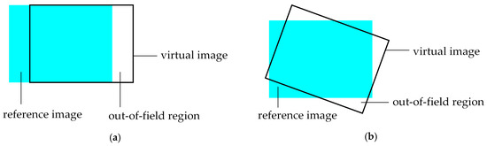
Figure 3.
Positional relationship between reference view and virtual view: (a) Horizontal translation; and (b) Rotation and translation.
3.1.1. Calculation of the Extended Region
The pinhole camera model is used in the 3D warping process. Assuming that the world coordinate system coincides with the reference camera coordinate system, the relationship between the associated pixels in the reference image and the virtual image can be defined as:
where and are the corresponding pixels of the 3D space point in the reference image and the virtual image, i.e., and . and are the depth values of two pixels. and are intrinsic matrixes of the reference camera and the virtual camera. The rotation matrix and the translation matrix represent the transformation from the reference view to the virtual view.
After the virtual image is obtained by the DIBR algorithm, we mark the hole pixels on the image boundary and inversely map them to the reference view by using (1) to calculate the size of the extended region. It is noted that the depth values of these hole pixels are unknown. Our calculation is under the assumption that these boundary pixels have similar depth values to those of the reference image if there are no additional foreground objects in the extension region. Therefore, the depth values of the boundary pixels in virtual image come from the processing result of the reference image boundary with a Gaussian lowpass filter.
The coordinate range of original reference image is -. After the hole pixels on the virtual image boundary are re-projected into the reference image plane, the minimum coordinate and maximum coordinate of these pixels can be obtained. Since these pixels are outside the imaging range of the reference view, the dimensions of the extended region in the horizontal and vertical directions are formulated as:
The extended reference image and its depth image are shown in Figure 4a,b, respectively. The extended region is marked and then filled by the inpainting method in the later section. It can be seen that the original reference image is located in the center, which facilitates the 3D warping computation and the extraction of the virtual image.

Figure 4.
Extended reference image and its depth image: (a) Extended reference image; and (b) extended depth image.
3.1.2. Extended Region Filling
Criminisi’s algorithm is an effective image inpainting method with three steps: priority calculation, best matching patch searching and priority updating. In this paper, the Criminisi’s algorithm is optimized to fill different types of holes. In this section, the extended region in the depth image is filled first. Then the depth information is used to fill the extended region in the reference image.
1 Criminisi’s inpainting algorithm
As shown in Figure 5, represents the entire image, is the hole region to be filled, the source region and define as . indicates the boundary of the hole. In order to determine the fill order, the priority of all pixels needs to be computed for all pixels on the boundary . In the original algorithm, the computation of the priority takes into account two factors: the amount of known information and the amount of structural information contained in the patch. For pixel on the , is the square patch centered at . The priority of is given by:
where is the confidence term and is the data term. They are defined as follows:
where is the area of , which means the number of pixels within the patch , is a normalization factor, for a typical gray-level image , is a unit vector orthogonal to the front in the point , is the direction of the isophote, and denotes the orthogonal operator. It can be seen that the confidence term gives higher priority to the patches, which have more non-hole pixels. The isophote reflects the structure of the image, and therefore, the data term gives higher priority to the patches, which are on the continuation of strong edges to encourage linear structures to be synthesized first. During initialization, the function is set to for hole pixels in , and for else.
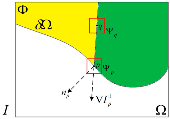
Figure 5.
Notation diagram for Criminisi’s algorithm.
After the point with the highest priority is found, the patch is ready to be filled. The original algorithm traverses the source region and searches for the patch with the highest similarity to by using the Sum of Squared Difference (SSD) between the two patches as the matching criterion. is determined as follows:
where the calculation of SSD is done in the RGB color space and only contains non-hole pixels in the two patches.
When the hole region of is filled, the confidence term is updated in the region limited by as follows:
the updated confidence term is used for the next calculation of priority. Then repeat the above process until all holes in the extended region are filled.
2 Proposed inpainting method
For extended region filling, it is necessary to maintain the spatial locality of the texture. In our method, the source region is no longer set to the valid region of the entire image, but the region with size centered at in the best matching patch searching process. The extended region in the depth image is filled first, thus the depth information can be used to search the best matching patch for the extended region filling in the reference image as follows:
where the former term indicates the similarity between the two patches on the color information, and the latter term indicates the depth similarity between the two patches. By updating the similarity measure, the patch with the same depth level is given a preference.
In the original inpainting algorithm, a fixed size patch is applied in the whole inpainting process. In fact, an image always contains multiple textures and edge structures. The high-frequency components of the image contain a large amount of detail and edges, while the low-frequency components make up the base texture of the image. Therefore, a smaller patch should be used in the high-frequency region to ensure the correct extension of edge structure, and for the relatively flat region, a larger patch is applied to prevent the staircase effect and speed up the hole filling. Since the gradient value can effectively reflect the change of the spatial frequency in the image, in this paper, the size of the patch is adaptively adjusted based on the gradient value. The gradient value of the pixel is calculated as follows:
by traversing all pixels on the boundary of holes, the maximum and minimum gradient values can be obtained, i.e., and . Then, the size of the patch with highest priority is determined by Equation (10):
where the initial size of the patch is set to . The coefficient values are defined by the difference between and . The difference is divided into four parts on average, and the pixel with larger gradient value will fall into the threshold range with smaller patch size. Adaptive patch size can prevent the erroneous extension of textures and structures. The inpainting results of the extended reference image and its depth image are shown in Figure 6, which are used in subsequent 3D warping for virtual image generation and OFRs filling.
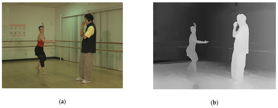
Figure 6.
Inpainting results of extended reference image and its depth image: (a) Inpainting result of extended reference image; and (b) inpainting result of extended depth image.
3.2. Depth Image Preprocessing
The quality of the depth image has a great impact on the rendering of the virtual view. The depth value usually mutates at the junction of the foreground and the background in the depth image. The ghosts are mainly caused by the inaccurate depth values of foreground boundary, causing the foreground pixels to be projected into the background region. In addition, the disocclusion is usually the background region occluded by the foreground in the reference view, which becomes visible in the virtual view. It often appears between the foreground and the background in the virtual image, depending on the location of the virtual view. Because of artifacts, both sides of the disoccluded region may be foreground pixels. Subsequent hole filling algorithm will further spread the error and seriously reduce the quality of the virtual view.
In order to remove the ghosts and project them to the correct space, in this paper, we propose a depth image preprocessing method to refine the depth values of the pixels near the boundary of the foreground. Since only several pixels in the depth image are processed, the 3D perception of the synthesized view can be effectively improved without significantly reducing the quality of the depth image.
In the preprocessing algorithm, we first determine the foreground boundary to be refined based on the external parameters of the virtual view. In general, ghosts and disocclusions occur on the right side of the foreground for the right synthesized view, and similar situations for the other locations of virtual view. Therefore, only one side of the foreground boundary needs to be refined. In this paper, we take the synthesis of the right virtual view for example. The detection of the foreground boundary is performed in the depth image. All pixels are scanned to determine whether adjacent points in the horizontal direction are still adjacent in the virtual view. If not, holes or overlap of pixels will appear in the virtual image. The depth image can reflect the distance from the object to the camera, which is expressed as the depth value in the image. The foreground and adjacent background usually have different depth values, and disocclusion occur on the region with sharp depth transition. Therefore, the boundaries to be processed are detected according to the degree of depth discontinuity and marked as follows:
where means the depth value of the pixel in reference image, is used to avoid the depth value of other foreground being changed. , and is the width of the preprocessing template and is set to 7 in our experiment. The threshold is set according to the depth distribution of the depth image.
After obtaining the mask image, the overlap of the marked foreground pixel with other background pixels in the virtual image is detected. If the overlap appears, the related foreground pixel will not be refined to avoid two types of backgrounds appear at the boundary of foreground in the virtual image. Overlap detection is achieved through the original 3D warping process. Each marked pixel is assigned a label to record the overlap of the pixels. If the pixel overlaps with other pixels in the virtual image and the depth difference between them is greater than , the value of label is set to 1, and vice versa is 0. The foreground pixels that need not be refined in the mask image are filtered as follows:
The depth value of the marked pixels and their horizontal neighbor pixels is refined using a template. For pixels in the template whose depth value are lower than the marked pixel, their depth values are replaced with the depth value of the marked pixel. Figure 7 shows an example of refinement process. Figure 7a is a row of pixels in the reference image, where G-L are the foreground pixels and the rest are the background pixels. It is noted that the pixel L is also given the background depth value, resulting in separation from adjacent foreground pixel K in the virtual image, as shown in Figure 7b. During the preprocessing, the pixel K is detected and marked. Since K does not overlap with the background pixel in the virtual image, the result of the refinement is shown in Figure 7c. The depth values of L-M are replaced and the synthesized image with depth image preprocessing is shown in Figure 7d. It can be seen that the ghost is removed and the background pixels are on both sides of the disocclusion region, which can reduce the penetration of foreground texture. For virtual views on the left or other sides, the refinement of foreground boundaries is similar with the method mentioned above. Figure 8 shows the preprocessing result of the actual image and verifies that the proposed method has a good effect on ghost removal.
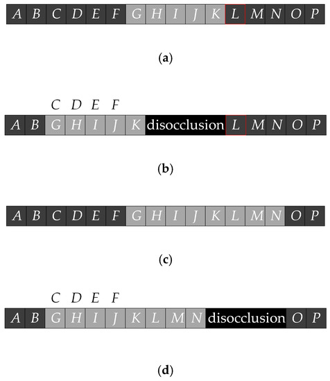
Figure 7.
The example of refinement process: (a) Original reference image; (b) synthesized image without depth image preprocessing; (c) reference image with depth value refinement; (d) and synthesized image after depth image preprocessing.
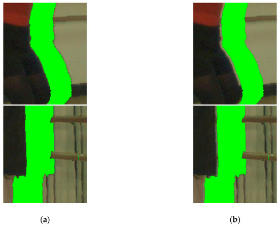
Figure 8.
Preprocessing result of actual image: (a) Synthesized image without depth image preprocessing; and (b) synthesized image after depth image preprocessing.
3.3. Modified 3D Warping
The second step of 3D warping is optimized in this section, and the preprocessed depth image is also used here to generate the virtual image. Since cracks usually appear inside the object and are 1–2 pixels wide, an adaptive one-to-four method is applied to reduce cracks and fill them with the neighbor valid pixels. For each pixel in the reference image, its corresponding target pixel is obtained by the 3D warping. Four results are provided from the judgment of whether and are integers as follows:
- If both and are integers, the value of is copied to the in the virtual image, i.e., .
- If is an integer and is not an integer, is rounded up and down to get the nearest integer and , then .
- If is not an integer and is an integer, is rounded up and down to get the nearest integer and , then .
- If both and are not integers, they are rounded up and down to get , , , , then .
Figure 9 shows an example of the adaptive one-to-four method. The pixel in the reference image is mapped to the position in the virtual image. By default, the pixel is copied to because pixel coordinates can only be integers. After adding the one-to-four method, will be copied to the pixel , , , and , thus greatly reducing the appearance of cracks. At the same time, this method may also cause the overlapping of pixels. When determining which one of the overlapping pixels should be displayed in the image, the pixel in the first situation mentioned above has the highest priority because its coordinate value is accurate. For other situations, the depth values of these overlapping pixels are compared. According to the occlusion relationship between objects, the foreground pixel, which has the highest depth value is selected as the final result. If there are multiple pixels with the highest depth value, it usually means that they are from the same object surface, and the values of these pixels are averaged as a result. For example, in Figure 9, pixel , and are all projected to but only can be seen in the virtual image, i.e., pixel . In addition, since the extended reference image and depth image are used in the 3D warping, the resulting image needs to be cropped to obtain the target virtual image.
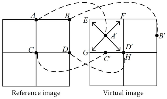
Figure 9.
Schematic diagram of the modified 3D warping.
3.4. Disocclusions Filling
Disocclusions are caused by the discontinuity of depth value, and usually belong to the background regions. Therefore, the hole filling is preferred to start from the background side. Pixels on the background boundaries should be given higher priority, while the confidence term and data term cannot be ignored. For depth image with multiple depth layers or many foreground objects, using a global threshold to distinguish foreground and background is a difficult task. In this paper, a local background-first hole filling method is proposed to handle the disocclusions. The pixels around each hole are divided into foreground and background by applying an adaptive threshold, as well as depth information is used to guide the priority computing and the search of the best matching patch.
Through the 3D warping, both the color image and the depth image of the virtual view are obtained, and the positions of holes in the two images are corresponding. In the virtual depth image, based on the depth distribution, the foreground and background pixels are determined within the minimum-bounding rectangle of each hole. In this case, we use the Otsu thresholding method to set the separation threshold for each hole. In order to eliminate the effect of outliers, 5% valid pixels in each rectangle with highest and lowest depth values are removed before the computing of threshold. Then the threshold is applied to distinguish the foreground and background pixels near each hole as follows:
where is the point within the minimum bounding rectangle of hole . The threshold of each hole is also applied to the priority calculation for disocclusion filling. Since the original inpainting algorithm causes the foreground and background pixels to spread simultaneously in the disocclusion, we refine the priority calculation based on the depth information as follows:
where is depth term and is background term. They are given by:
where is the number of valid pixels in . and are the highest and lowest nonzero depth values in the virtual depth image, respectively. The depth term reflects the average depth value of the valid pixels in . Since disocclusions should be filled with background pixels, the patch, which has lower depth values, is given a higher priority. The background term represents the percentage of the local background pixels in the patch, and the patch with more background pixels is given a higher priority. The improved priority calculation ensures that when the confidence and data terms of the two patches are close, the one closer to the background can be preferentially filled. Especially for the depth image with multiple depth layers, the background term helps to correctly identify the foreground and background objects.
After determining the filling priorities, we search for the best matching patch in both the reference image and virtual image. Moreover, depth information is introduced to limit the searching region, so that the new source region is defined as:
where is the region which has large depth difference with and the depth difference is calculated by:
in our experiment, the source patch with is skipped in the search of the best matching patch to ensure that the disocclusion is filled by the pixels with same depth level. The limitation of the source region can avoid artifacts caused by the diffusion of the foreground texture. In addition, the adaptive patch size mentioned above is also applied here. Considering that the depth term and background term need to be updated at the end of each iteration, disocclusion filling of the virtual depth image and the color image are performed simultaneously.
4. Experimental Results
In order to evaluate the performance of the proposed method, the multi-view video plus depth sequences “Ballet” and “Breakdancers” provided by Microsoft Research are used in our experiment [30]. The sequence consists of eight viewpoints and each view contains 100 color images and corresponding depth images. The size of each frame is 1024 × 768. Camera parameters are known, including internal and external parameters. The synthesized virtual image is named after the tested sequence and projection information. For example, the sequence warped from the view 5 to view 4 of “Ballet” is named as BA54. The parameters of the proposed method are set as follows. Considering the size of the extended region, for BA54, BA56, BR43, and BR45, is set to 97, and for BA52 and BR41, which have a large baseline, is set to 217. In the “Ballet” sequence, a foreground object is far from another one, and there is a significant depth difference between the foreground and the adjacent background. But the in “Breakdancers” sequence, there are a series of objects with similar depth values. In this case, the preprocessing threshold is set to 25 and 15 for “Ballet” and “Breakdancers”, respectively.
In this section, subjective evaluation and objective evaluation are compared among the proposed and previous methods, including Criminisi’s exemplar-based image inpainting method [14], Daribo’s depth-aided inpainting method [15], divide-and-conquer hole-filling method [12], Oliveira’s inpainting-based method [16], and Kao’s disocclusions filling method [17]. In References [12,14,16,17], and the proposed method, the virtual view synthesis needs only a single reference image and its depth image, while the method in Reference [15] is under the assumption that the depth image of the virtual view is given.
The results of subjective comparisons are shown in the following figures. Figure 10a,b show the synthesized virtual images with the original DIBR algorithm for BA54 and BA52. It can be seen that cracks and pixel overlapping reduce the image quality. The rendering results of the modified 3D warping for BA54 and BA52 are shown in Figure 10c,d. Unwanted cracks and overlapping pixels are removed, then the remaining artifacts in the virtual image are the OFRs and disocclusions.
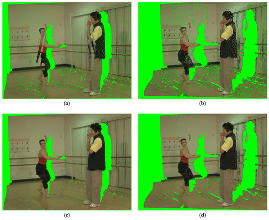
Figure 10.
Visual quality comparison of 3D warping: (a) Synthesized result of the original 3D warping for BA54; (b) synthesized result of the original 3D warping for BA52; (c) synthesized result of the modified 3D warping for BA54; and (d) synthesized result of the modified 3D warping for BA52.
The subjective quality comparison of the disocclusion filling results in the case of small baseline is shown in Figure 11. In Criminisi’s method [14], foreground objects are sampled to fill the disocclusion, resulting a decline in the quality of the virtual view, as shown in Figure 11b. In Daribo’s method [15], although the calculation of priority is improved by introducing the depth variance of the patch, the existence of ghosts causes come defects in the disoccluded region, as shown in Figure 11c. The result of Lei’s method [12] is shown in Figure 11d, which has a good effect on the simple background texture, but some artifacts appear among the boundaries of foreground. For the complex background texture, the edge structure may be distorted which affects the visual quality. In Oliveira’s method [16], the priority consists of the confidence term and the depth term. While the hole filling starts from the background side, the lack of the data term makes the structure and texture difficult to maintain effectively, as shown in Figure 11e. In Kao’s method [17], the calculation among the three items of priority is changed from multiplication to addition based on [15], and a depth image preprocessing method is introduced. The filling result of disocclusion is shown in Figure 11f. For depth image with multiple depth layers, the foreground and background objects cannot be accurately identified based on the inverse of the depth variance. Compared with the previous methods, the proposed inpainting method combined with the adaptive patch size can successfully protect the foreground boundary and show a better result in Figure 11g.
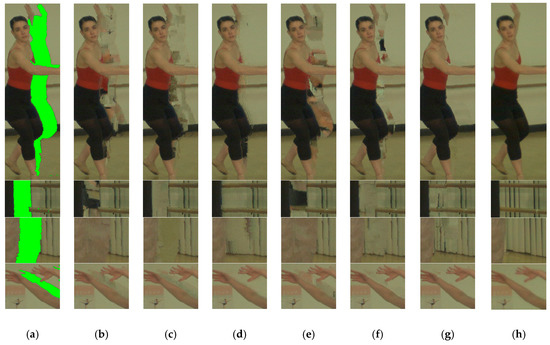
Figure 11.
Disocclusion filling results in the case of small baseline: (a) Disocclusions after DIBR; (b) Criminisi’s method; (c) Daribo’s method; (d) Lei’s method; (e) Oliveira’s method; (f) Kao’s method; (g) the proposed method; and (h) ground truth.
The results of OFRs filling are shown in Figure 12. It can be seen the proposed method outperforms the previous method. In the proposed method, OFRs are filled by the neighbor regions in the reference image, so that the penetration problem can be avoided, while the results of other methods include some artifacts, for example, the foreground object in the other region is sampled to fill the OFRs and the error texture is spread. For BA52 and BR41, due to the increase of baseline distance, disocclusions filling become more challenging. The quality comparison is shown in Figure 13. Although the area of the disocclusion becomes larger and part of the hole is no longer adjacent to the foreground, the proposed method still successfully maintains the boundary between the foreground and the background, and the filling result is most similar to the real texture.
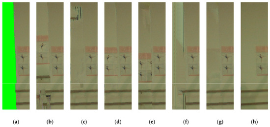
Figure 12.
OFRs filling results: (a) OFRs after DIBR; (b) Criminisi’s method; (c) Daribo’s method; (d) Lei’s method; (e) Oliveira’s method; (f) Kao’s method; (g) the proposed method; and (h) ground truth.
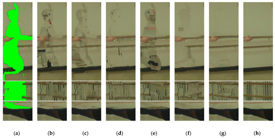
Figure 13.
Disocclusion filling results in the case of large baseline: (a) Disocclusions after DIBR; (b) Criminisi’s method; (c) Daribo’s method; (d) Lei’s method; (e) Oliveira’s method; (f) Kao’s method; (g) the proposed method; and (h) ground truth.
In order to evaluate the objective performance of the proposed method, in our experiment, peak signal-noise ratio (PSNR) and structural similarity (SSIM) [31] are used to evaluate the degree of similarity between the synthesized image and the ground truth at the target view. PSNR is used to measure the squared intensity differences of pixels in the two images, and SSIM is used to measure the structural similarity between the synthesized image and the ground truth. The higher PSNR and SSIM values mean the higher quality of the synthesized image. The average PSNR and SSIM for “Ballet” and “Breakdancers” are shown in Table 1 and Table 2. The results show that the proposed method achieves the overall best results. In the comparison of PSNR, the proposed method obtains 0.30–4.09 dB and 0.28–1.83 dB better results than the previous methods on “Ballet” and “Breakdancers”, respectively. The SSIM gains of the proposed method over the previous methods on “Ballet” and “Breakdancers” are 0.0011–0.0252 and 0.0025–0.0108, respectively. The results of the PSNR and SSIM comparison for each frame are shown in Figure 14. The proposed method always shows the best results for both large baseline distance and small baseline distance.

Table 1.
Average peak signal-noise ratio (PSNR) comparison of the proposed and previous methods.
Table 2.
Average structural similarity (SSIM) comparison of the proposed and previous methods.
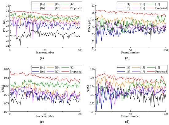
Figure 14.
Objective comparison results: (a) PSNR of BA54; (b) PSNR of BA52; (c) SSIM of BA54; and (d) SSIM of BA52.
The proposed method is running on a PC and implemented via MATLAB and Visual Studio. In addition to the limitations of hardware devices, the improvement of virtual image quality increases the computational complexity of the proposed method. In our method, the 3D warping process is performed four times and the image inpainting takes a lot of time, especially for priority calculation and best matching patch searching. Although we have reduced some computational amount by limiting the source region, our method still has more computational complexity than the original DIBR algorithm. On the one hand, the GPU- accelerated algorithms can be applied to each step of our method, and the hardware acceleration scheme provides the possibility for real-time application of the algorithm. In the implementation of the proposed method, the processing of pixel points can be computed in parallel. In addition, in disocclusions and OFRs filling, the calculations of the priority of pixel on the hole boundary and the matching cost between the patches can also be performed in parallel. Therefore, under the condition of applying algorithm and hardware parallel acceleration, the time for synthesizing the whole sequence does not increase too much. On the other hand, we mainly explore the contribution of artifacts handling method for single view rendering. during the whole process, we try to make the synthesized image closer to the ground truth. Furthermore, the temporal correlation of adjacent frames and the complementary relationship of multiple reference views are not exploited in this paper. The visual quality of our method for view interpolation may not be as good as the state-of-the-art multi-view rendering method due to the lack of valid pixels. For more complex scenes, such as alternating multiple foreground objects, there are only a few background pixels around the hole, and the proposed method may not be able to perfectly identify them and fill the holes. After all, our algorithm is based on traditional image processing algorithms. If deep learning techniques are introduced, the results may become better.
5. Conclusions
In this paper, a novel artifact handling method is proposed for virtual view synthesis, which fully utilizes the information in the depth image. For OFRs, we extend the reference view and fill it with a modified inpainting method. Pixels that are considered artifacts are detected during depth image preprocessing and then projected to the correct space. To deal with cracks and pixel overlapping, we present an adaptive one-to-four method to optimize 3D warping and select the correct pixel to display in the virtual image based on the depth information. The depth term and background term are introduced into the calculation of the priority to fill the disocclusion. The foreground and background are divided according to the depth value of the pixels around each hole instead of the global threshold. Furthermore, the source region is limited to prevent foreground pixels from being incorrectly sampled into the disoccluded region. Adaptive patch size is applied to improve the quality and accuracy of the image inpainting, taking into account the various textures in the image. The experimental results demonstrate that the proposed method shows satisfactory results in subjective and objective evaluation. Our future work will focus on two aspects. The first is to improve the visual quality of the synthesized view by using the temporal correlation between the adjacent frames of the reference video and the complementary relationship of multiple reference views. The second is to introduce the deep learning algorithm into the hole filling process. Through the training of deep networks, the computation time of the algorithm will be effectively reduced without degrading the quality of the virtual image. In addition, artifact handling based on deep learning can be robust to complex scenes through extensive training in different scenes.
Author Contributions
Conceptualization, X.C. and H.L.; methodology, H.L. and Y.W.; software, S.R.; validation, H.L., H.X. and S.R.; data curation, H.L.; writing—original draft preparation, X.C., H.L. and Y.W.; writing—review and editing, X.C., H.L. and H.C.; supervision, X.C.; project administration, X.C. and Y.W.
Funding
This research was funded by the National Major Project of Scientific and Technical Supporting Programs of China during the 13th Five-year Plan Period, grant number 2017YFC0109702, 2017YFC0109901 and 2018YFC0116202.
Acknowledgments
The authors would like to thank the Interactive Visual Media Group at Microsoft Research.
Conflicts of Interest
The authors declare no conflict of interest.
References
- Tech, G.; Chen, Y.; Muller, K.; Ohm, J.R.; Vetro, A.; Wang, Y.K. Overview of the Multiview and 3D Extensions of High Efficiency Video Coding. IEEE Trans. Circuits Syst. Video Technol. 2016, 26, 35–49. [Google Scholar] [CrossRef]
- Tanimoto, M. Overview of free viewpoint television. Signal Process. Image Commun. 2006, 21, 454–461. [Google Scholar] [CrossRef]
- Luo, G.B.; Zhu, Y.S.; Li, Z.T.; Zhang, L.M. A Hole Filling Approach based on Background Reconstruction for View Synthesis in 3D Video. In Proceedings of the 2016 IEEE Conference on Computer Vision and Pattern Recognition, New York, NY, USA, 27–30 June 2016; pp. 1781–1789. [Google Scholar]
- Fehn, C. Depth-image-based rendering (DIBR), compression and transmission for a new approach on 3D-TV. In Stereoscopic Displays and Virtual Reality Systems XI; Spie-Int Soc Optical Engineering: Bellingham, DC, USA, 2004; pp. 93–104. [Google Scholar]
- Wang, L.H.; Huang, X.J.; Xi, M.; Li, D.X.; Zhang, M. An Asymmetric Edge Adaptive Filter for Depth Generation and Hole Filling in 3DTV. IEEE Trans. Broadcast. 2010, 56, 425–431. [Google Scholar] [CrossRef]
- Mori, Y.; Fukushima, N.; Yendo, T.; Fujii, T.; Tanimoto, M. View generation with 3D warping using depth information for FTV. Signal Process. Image Commun. 2009, 24, 65–72. [Google Scholar] [CrossRef]
- Muddala, S.M.; Sjostrom, M.; Olsson, R. Virtual view synthesis using layered depth image generation and depth-based inpainting for filling disocclusions and translucent disocclusions. J. Vis. Commun. Image Represent. 2016, 38, 351–366. [Google Scholar] [CrossRef]
- Zhang, L.; Tam, W.J.; Wang, D.M. Stereoscopic image generation based on depth images. In Proceedings of the 2004 International Conference on Image Processing, Singapore, 24–27 October 2004; pp. 2993–2996. [Google Scholar]
- Zhang, L.; Tam, W.J. Stereoscopic image generation based on depth images for 3D TV. IEEE Trans. Broadcast. 2005, 51, 191–199. [Google Scholar] [CrossRef]
- Chen, W.Y.; Chang, Y.L.; Lin, S.F.; Ding, L.F.; Chen, L.G. Efficient depth image-based rendering with edge dependent depth filter and interpolation. In Proceedings of the 2005 IEEE International Conference on Multimedia and Expo, Amsterdam, The Netherlands, 6 July 2005; pp. 1315–1318. [Google Scholar]
- Lu, X.; Wei, F.; Chen, F. Foreground-Object-Protected Depth Map Smoothing for DIBR. In Proceedings of the 2012 IEEE International Conference on Multimedia and Expo, Melbourne, VIC, Australia, 9–13 July 2012; pp. 339–343. [Google Scholar]
- Lei, J.J.; Zhang, C.C.; Wu, M.; You, L.; Fan, K.F.; Hou, C.P. A divide-and-conquer hole-filling method for handling disocclusion in single-view rendering. Multimed. Tools Appl. 2017, 76, 7661–7676. [Google Scholar] [CrossRef]
- Liu, W.; Ma, L.Y.; Qiu, B.; Cui, M.Y.; Ding, J.W. An efficient depth map preprocessing method based on structure-aided domain transform smoothing for 3D view generation. PLoS ONE 2017, 12, 20. [Google Scholar] [CrossRef] [PubMed]
- Criminisi, A.; Perez, P.; Toyama, K. Region filling and object removal by exemplar-based image inpainting. IEEE Trans. Image Process. 2004, 13, 1200–1212. [Google Scholar] [CrossRef] [PubMed]
- Daribo, I.; Saito, H. A Novel Inpainting-Based Layered Depth Video for 3DTV. IEEE Trans. Broadcast. 2011, 57, 533–541. [Google Scholar] [CrossRef]
- Oliveira, A.; Fickel, G.; Walter, M.; Jung, C. Selective hole-filling for depth-image based rendering. In Proceedings of the 2015 IEEE International Conference on Acoustics, Speech and Signal Processing (ICASSP), Brisbane, QLD, Australia, 19–24 April 2015; pp. 1186–1190. [Google Scholar]
- Kao, C.C. Stereoscopic image generation with depth image-based rendering. Multimed. Tools Appl. 2017, 76, 12981–12999. [Google Scholar] [CrossRef]
- Luo, G.B.; Zhu, Y.S.; Guo, B. Fast MRF-Based Hole Filling for View Synthesis. IEEE Signal Process. Lett. 2018, 25, 75–79. [Google Scholar] [CrossRef]
- Luo, G.B.; Zhu, Y.S. Foreground Removal Approach for Hole Filling in 3D Video and FVV Synthesis. IEEE Trans. Circuits Syst. Video Technol. 2017, 27, 2118–2131. [Google Scholar] [CrossRef]
- Han, D.X.; Chen, H.; Tu, C.H.; Xu, Y.Y. View synthesis using foreground object extraction for disparity control and image inpainting. J. Vis. Commun. Image Represent. 2018, 56, 287–295. [Google Scholar] [CrossRef]
- Criminisi, A.; Blake, A.; Rother, C.; Shotton, J.; Torr, P.H.S. Efficient dense stereo with occlusions for new view-synthesis by four-state dynamic programming. Int. J. Comput. Vis. 2007, 71, 89–110. [Google Scholar] [CrossRef]
- Yao, C.; Tillo, T.; Zhao, Y.; Xiao, J.M.; Bai, H.H.; Lin, C.Y. Depth Map Driven Hole Filling Algorithm Exploiting Temporal Correlation Information. IEEE Trans. Broadcast. 2014, 60, 394–404. [Google Scholar] [CrossRef]
- Sun, W.X.; Au, O.C.; Xu, L.F.; Li, Y.J.; Hu, W. Novel temporal domain hole filling based on background modeling for view synthesis. In Proceedings of the 2012 IEEE International Conference on Image Processing, Orlando, FL, USA, 30 September–3 October 2012; pp. 2721–2724. [Google Scholar]
- Deng, Z.; Wang, M. Reliability-Based View Synthesis for Free Viewpoint Video. Appl. Sci. 2018, 8, 823. [Google Scholar] [CrossRef]
- Kauff, P.; Atzpadin, N.; Fehn, C.; Muller, M.; Schreer, O.; Smolic, A.; Tanger, R. Depth map creation and image-based rendering for advanced 3DTV services providing interoperability and scalability. Signal Process. Image Commun. 2007, 22, 217–234. [Google Scholar] [CrossRef]
- Zhu, C.; Li, S. Depth Image Based View Synthesis: New Insights and Perspectives on Hole Generation and Filling. IEEE Trans. Broadcast. 2016, 62, 82–93. [Google Scholar] [CrossRef]
- Luo, G.B.; Zhu, Y.S. Hole Filling for View Synthesis Using Depth Guided Global Optimization. IEEE Access 2018, 6, 32874–32889. [Google Scholar] [CrossRef]
- Li, S.; Zhu, C.; Sun, M.T. Hole Filling with Multiple Reference Views in DIBR View Synthesis. IEEE Trans. Multimed. 2018, 20, 1948–1959. [Google Scholar] [CrossRef]
- Li, Y.Z.; Claesen, L.; Huang, K.; Zhao, M.L. A Real-Time High-Quality Complete System for Depth Image-Based Rendering on FPGA. IEEE Trans. Circuits Syst. Video Technol. 2019, 29, 1179–1193. [Google Scholar] [CrossRef]
- Zitnick, C.L.; Kang, S.B.; Uyttendaele, M.; Winder, S.; Szeliski, R. High-quality video view interpolation using a layered representation. ACM Trans. Graph. 2004, 23, 600–608. [Google Scholar] [CrossRef]
- Wang, Z.; Bovik, A.C.; Sheikh, H.R.; Simoncelli, E.P. Image quality assessment: From error visibility to structural similarity. IEEE Trans. Image Process. 2004, 13, 600–612. [Google Scholar] [CrossRef]
© 2019 by the authors. Licensee MDPI, Basel, Switzerland. This article is an open access article distributed under the terms and conditions of the Creative Commons Attribution (CC BY) license (http://creativecommons.org/licenses/by/4.0/).