1. Introduction
For brittle materials such as rock, tension failure is one of the most significant failure modes [
1]. In a complex stress field of underground mining or geotechnical practice, tension damage/failure in rock masses is easily triggered and dominant because: (1) The tensile strength (
σt) of rocks is much lower than their compressive strength, and (2) joints and fractures of rock mass can offer little resistance to tensile stress [
2]. After an excavation is taken underground, tension failure and its induced fractures will occur in surrounding rock masses near the opening [
3,
4,
5,
6,
7,
8]. The initiated fractures will develop/propagate and bring weakening effects on the rock masses under the effect of time and constant stress disturbance (development of entry or shaft, mining activities, etc.). As it is well established that the Young’s modulus of a rock mass is directly related to the fracture or joint intensity [
9,
10,
11,
12,
13], the aforementioned fracture development can be described as a Young’s modulus degradation process in the view of an equivalent material method in continuum mechanics.
The macroscopic mechanical behaviors of intact and jointed rocks have been widely investigated, most of which has been focused on the material behaviors in compression [
14,
15,
16]. However, unlike metals or other materials, rocks are generally bi-modularity materials with different Young’s moduli and Poisson’s ratios in compression and tension. Previous studies done by direct tension tests showed that the Young’s modulus in tension (
Et) was always no larger than the compressive Young’s modulus (
Ec) [
17,
18,
19,
20,
21]. Hawkes et al. [
17] conducted direct tension tests on different kinds of rocks, and the results showed that the ratio of
Et/Ec was 1/9 for Barre sandstone and 0.5 for Barre granite. Stimpson and Chen [
20] acquired the ratios to be 0.5, 1.0, 0.7, and 0.3–0.4 for four different rocks from cyclic loading uniaxial tension and compression tests. Similar results were obtained by Yu et al. [
22] with an originally developed loading frame for direct tension. It has been addressed by researchers that the improper assumption that E
t equals to
Ec may lead to errors in calculating stress distributions around underground openings by means of analytical or numerical analysis, as well as in determining the tensile strength of rocks with Brazilian tests [
18,
20,
22,
23].
To date, it is still quite challenging to conduct direct uniaxial tension tests on intact rock specimens in laboratories due to the difficulties in avoiding: 1) Unfavorable stress concentration over the grip and 2) bending moments due to the non-coaxial gripping and curvature of the specimen. Various attempts have been made in this regard. Stimpson and Chen [
20] conducted their tests on rock samples with a special hollow cylinder geometry. Okubo and Fukui [
24] glued the rock samples directly to the loading platen to carry out direct tension tests. Fahimifar and Malekpour [
25] developed a direct tension apparatus with hard steel tension jaws to ensure the connection between samples and the apparatus and that the applied load is pure tension. Fuenkajorn and Klanphumeesri [
26] developed a compression-to-tension load converter to determine the tensile strength and Young’s modulus from dog-bone-shaped specimens.
As described above, the Young’s modulus estimation for jointed rocks and rock masses is essential for stability analysis. However, rock specimens with joints or fractures are difficult to be prepared, and simplifications have to be made with rock-like materials (such as gypsum) or simple notches. Furthermore, the uniaxial tension tests rely on specially made, non-universal apparatuses.
In recent years, numerical and computational resources have taken significant leaps forward, and numerical methods have become strong and efficient research tools by overcoming the limitations in laboratory and physical tests. Some previous studies have been done with numerical modelling on the direct tension testing of rock specimens. Tang et al. [
1] studied the growth of micro-fractures in a specimen under uniaxial tension and the influence of heterogeneity on rock strength with a self-developed finite element code (RFPA2D). Wang et al. [
27] simulated crack initiation, propagation, and coalescence for intact, single-notched, and double-notched rock specimens with RFPA3D under uniaxial tension, and the effects of the separation distance and overlapping distance of the two notches were investigated. Hamdi et al. [
28] studied the model I fracture propagation in brittle rock under direct tension by means of a discrete element method. Guo et al. [
29] investigated fracture patterns in layered rocks under direct tension with a discrete element method.
According to the previous studies [
1,
27,
28,
29,
30,
31,
32], the numerical studies on rock specimens under uniaxial or direct tension loads mainly focus on fracture initiation and propagation within the specimens. However, the effects on the mechanical behaviors of strength and deformability, i.e., tensile strength and Young’s modulus in tension, of jointed rock specimens subjected to uniaxial tension load are barely discussed. In this study, rock specimens with various joint conditions are modeled with 3DEC (a 3-Dimension Distinct Element Code by Itasca) due to its capability in simulating the behaviors of joints (slip, separation, deformation, etc.) under mechanical loading, and the effects of joints on the tensile properties are studied by means of uniaxial tension numerical tests. Tests of rock samples with single joint, and multiple joints with different joint geometry parameters are designed, and their effects on the tensile properties of rock specimens are investigated. The goal of this study is to understand the effects of joints on the tensile properties of rocks.
2. Numerical Modelling
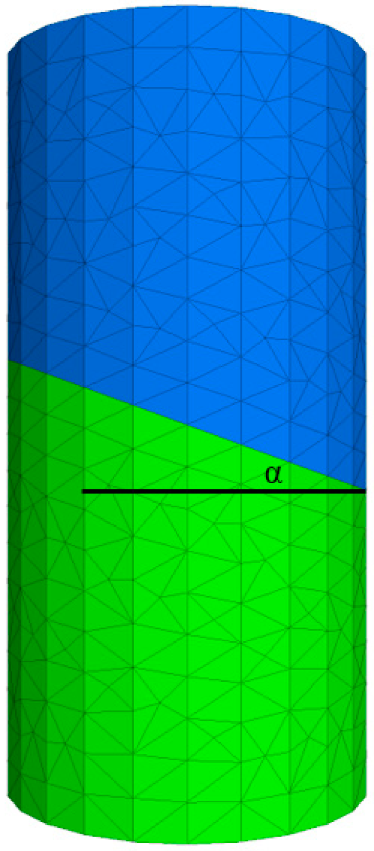
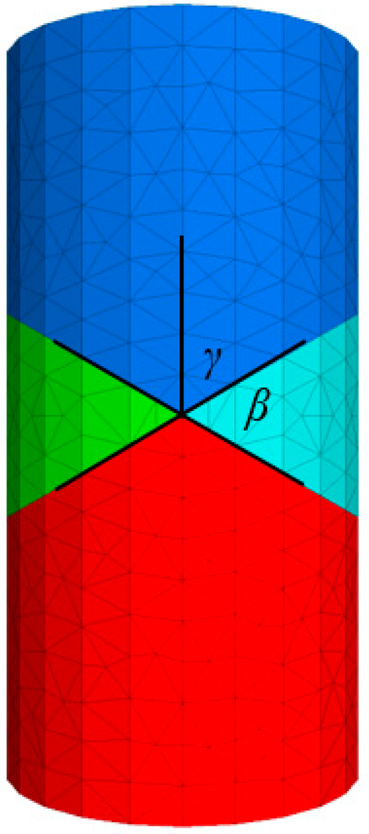
The numerical model is constructed by means of 3DEC, which is a three-dimensional numerical program employing the distinct element method for discontinuum modelling. In the following analysis, rock specimen models with different joint conditions (single, multiple parallel, and intersecting joints) are built, and the effects of joints on the tensile properties are investigated by applying a uniaxial tension load. The specimen model is a cylinder with 50 mm in diameter and 100 mm in height, as suggested by the International Society of Rock Mechanics (ISRM) [
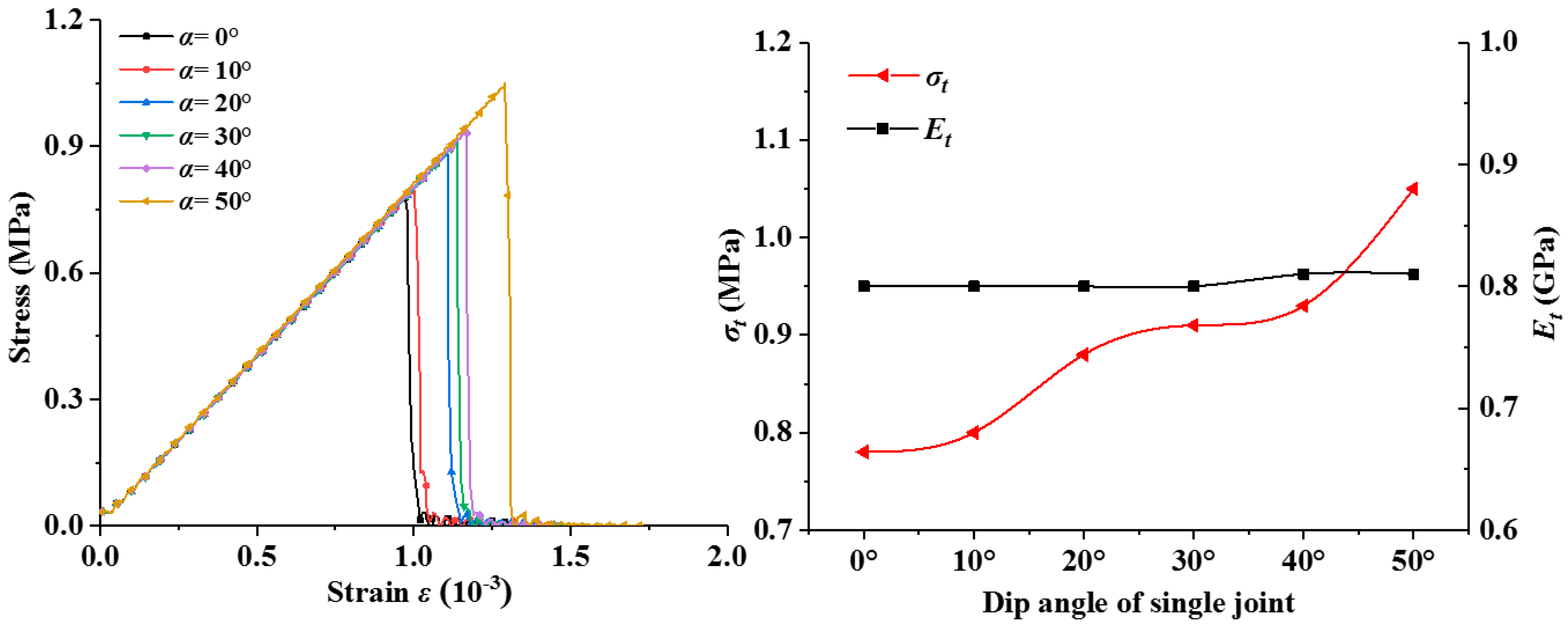
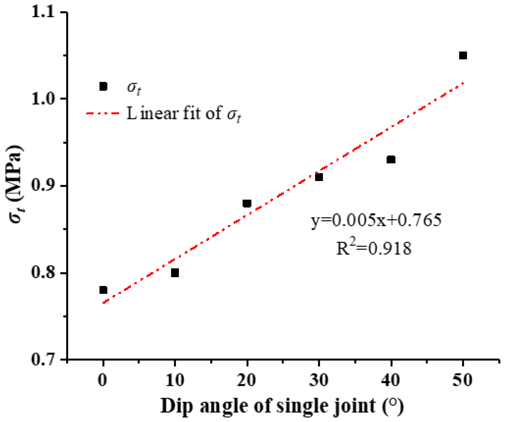
33]. All joints are considered to cut through the specimen. A constant rate of 0.005 mm/step is applied to the upper and lower boundary to simulate the uniaxial tension load. After the specimens fail in tension, 1000 extra steps are calculated to capture the after-peak behavior. With the obtained stress–strain curves,
σt and
Et under different joint conditions are calculated, and the effects of joint condition on the tensile strength (
σt) and
Et are hereby investigated.
In 3DEC, joints or fractures are considered as elements with mechanical properties. The rock and joint properties [
34] (listed in
Table 1 and
Table 2) are applied according to a study on tunnel stability analysis of an underground mine using 3DEC.
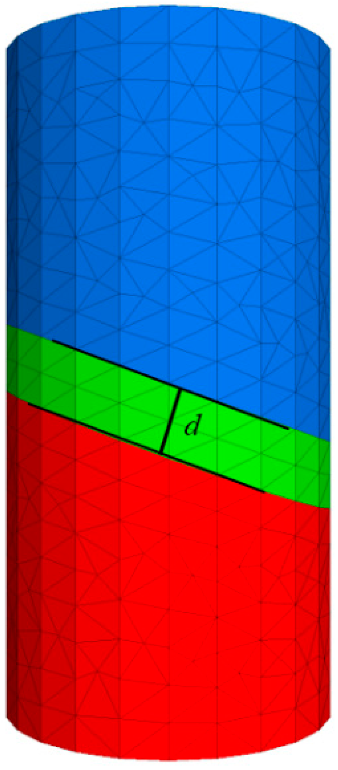
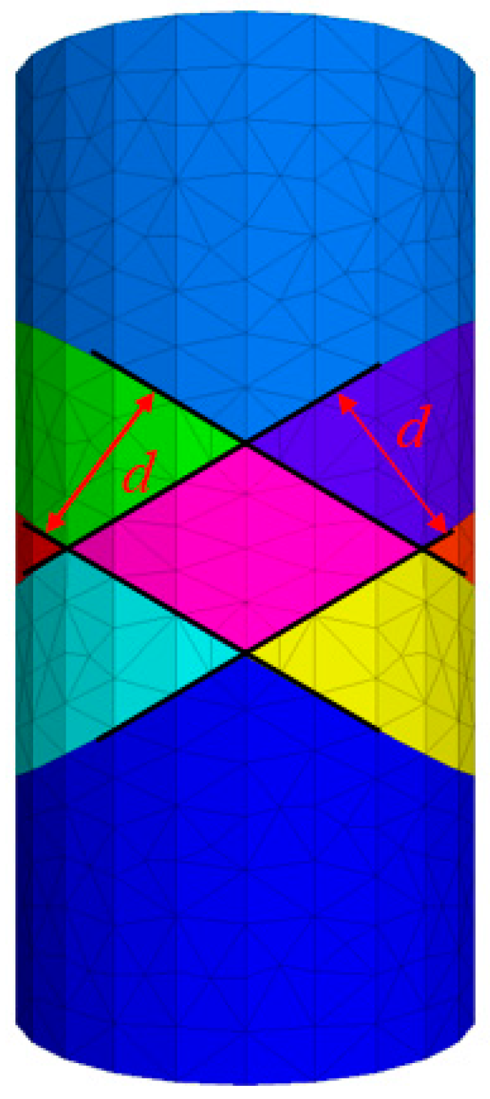
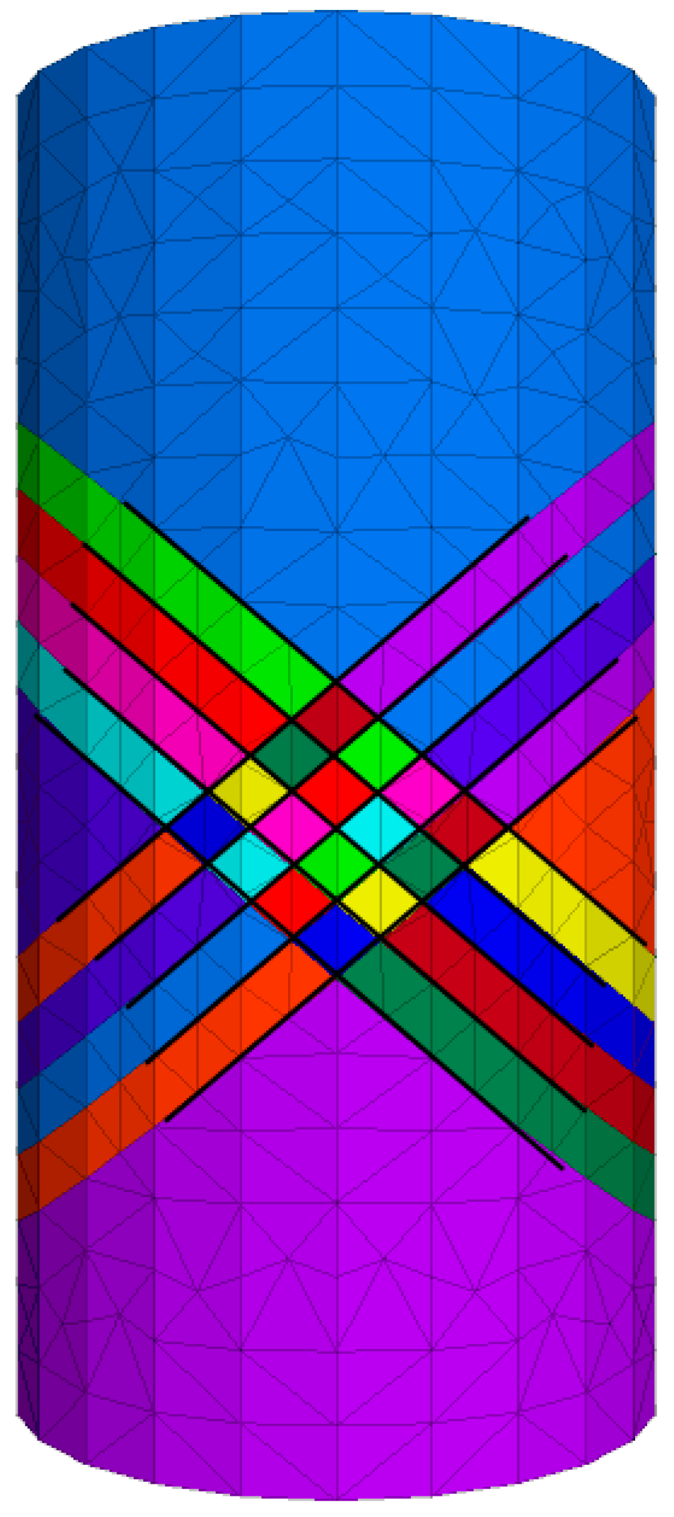
To study the effects of joints on the tensile properties of rocks, the rock specimens with various joint conditions were described and modelled with four geometry parameters of joints: α (the angle between the joint and the horizontal direction), d (the perpendicular distance between the two joints), β (the angle at which the two joints intersect), and n (the joint density).
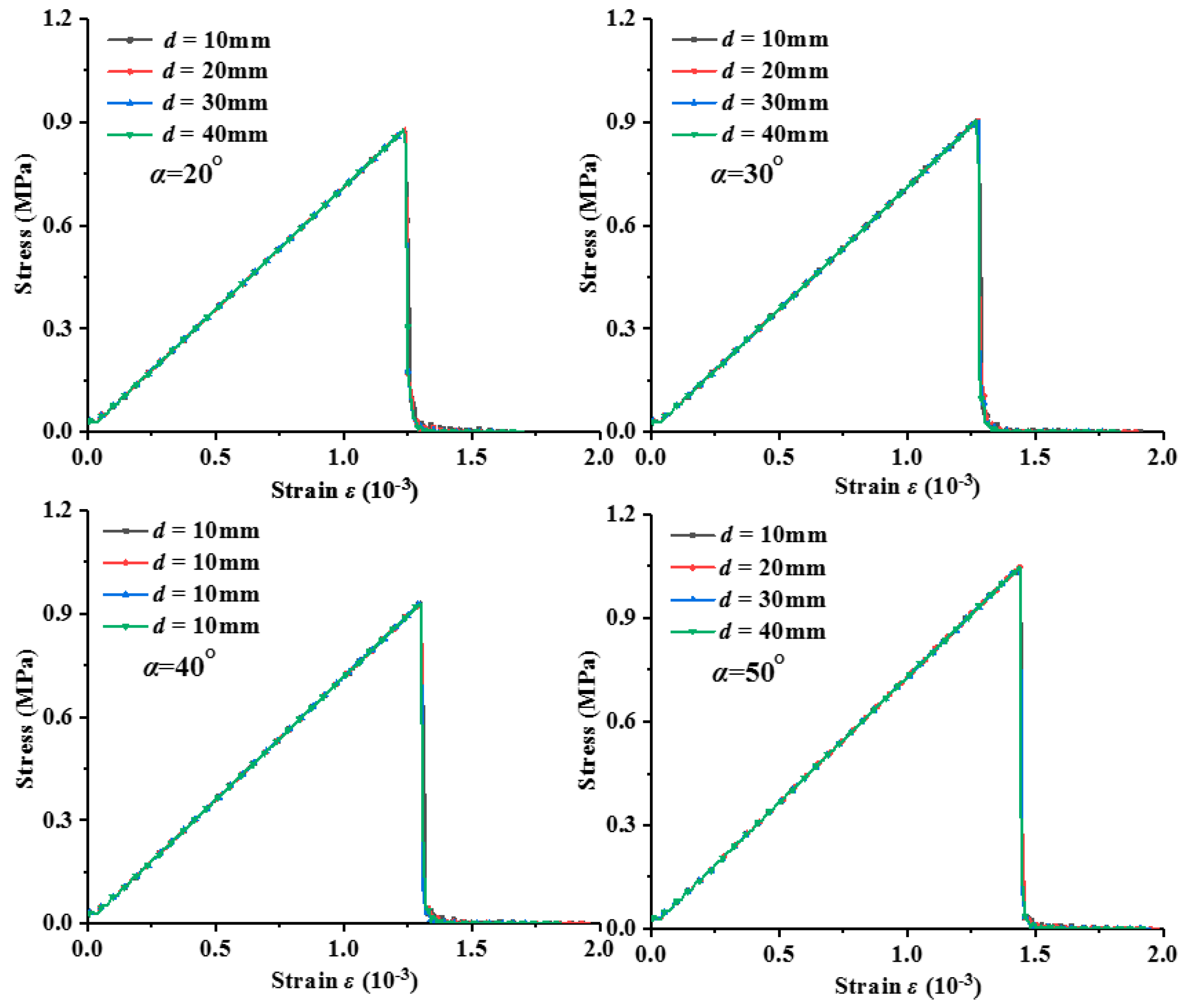
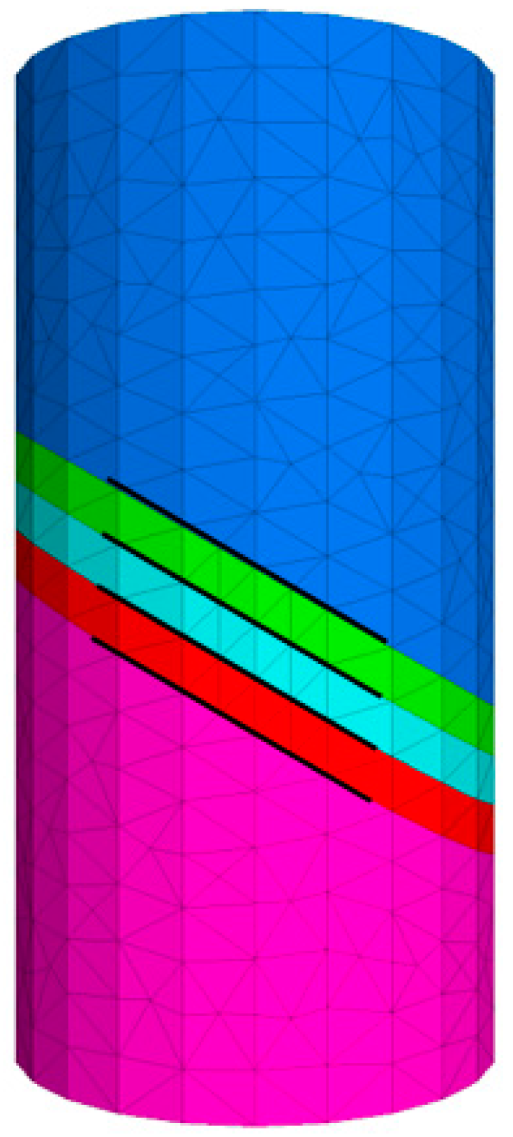
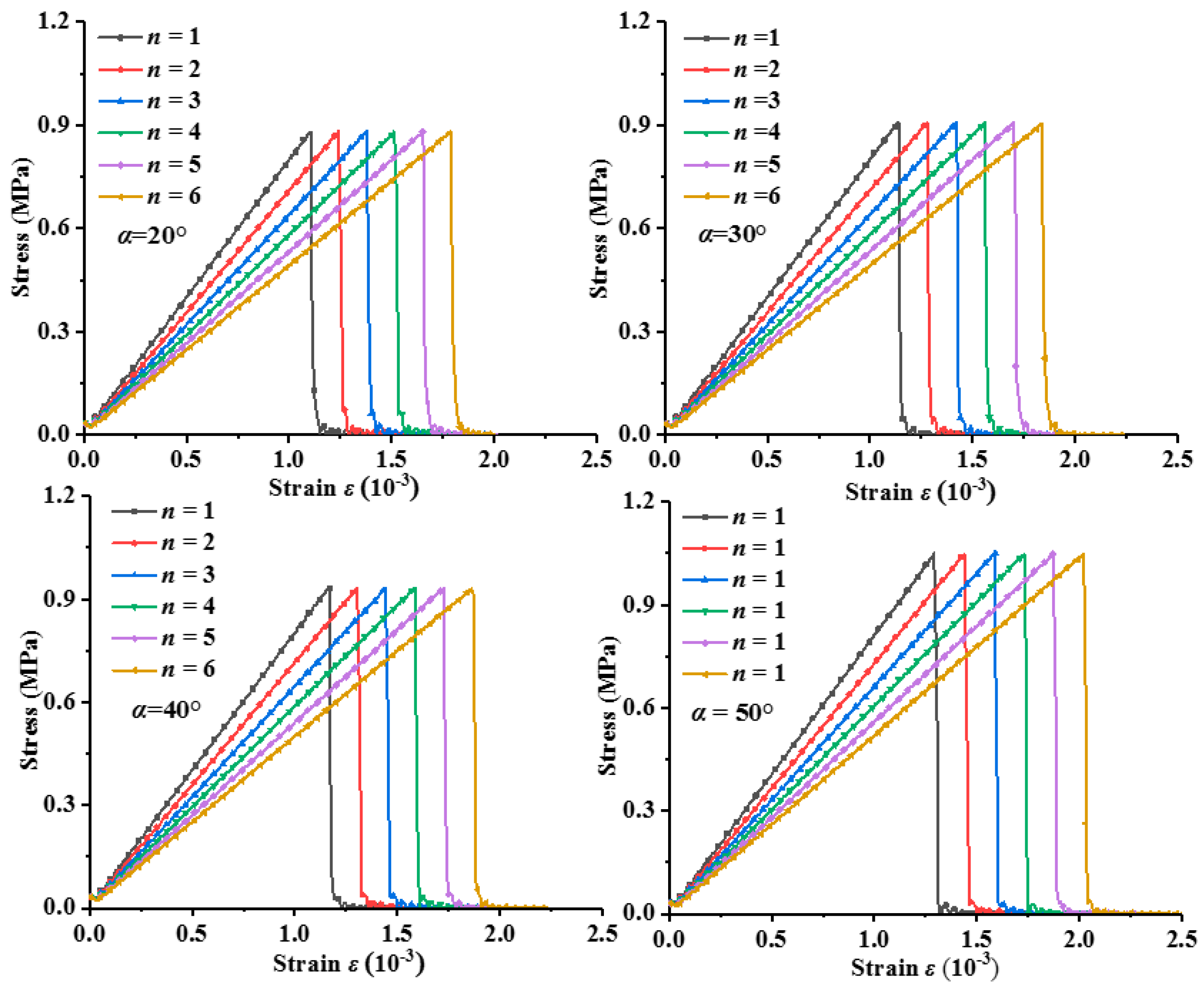
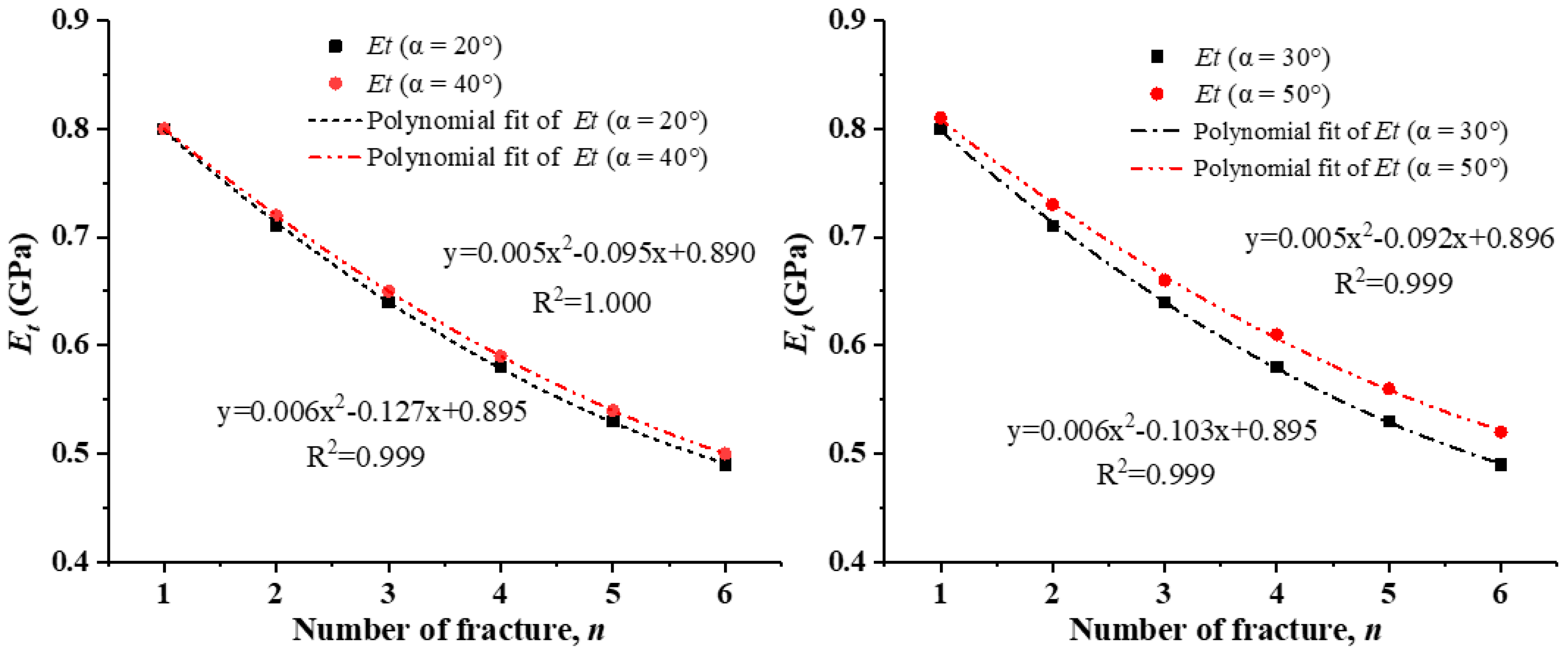
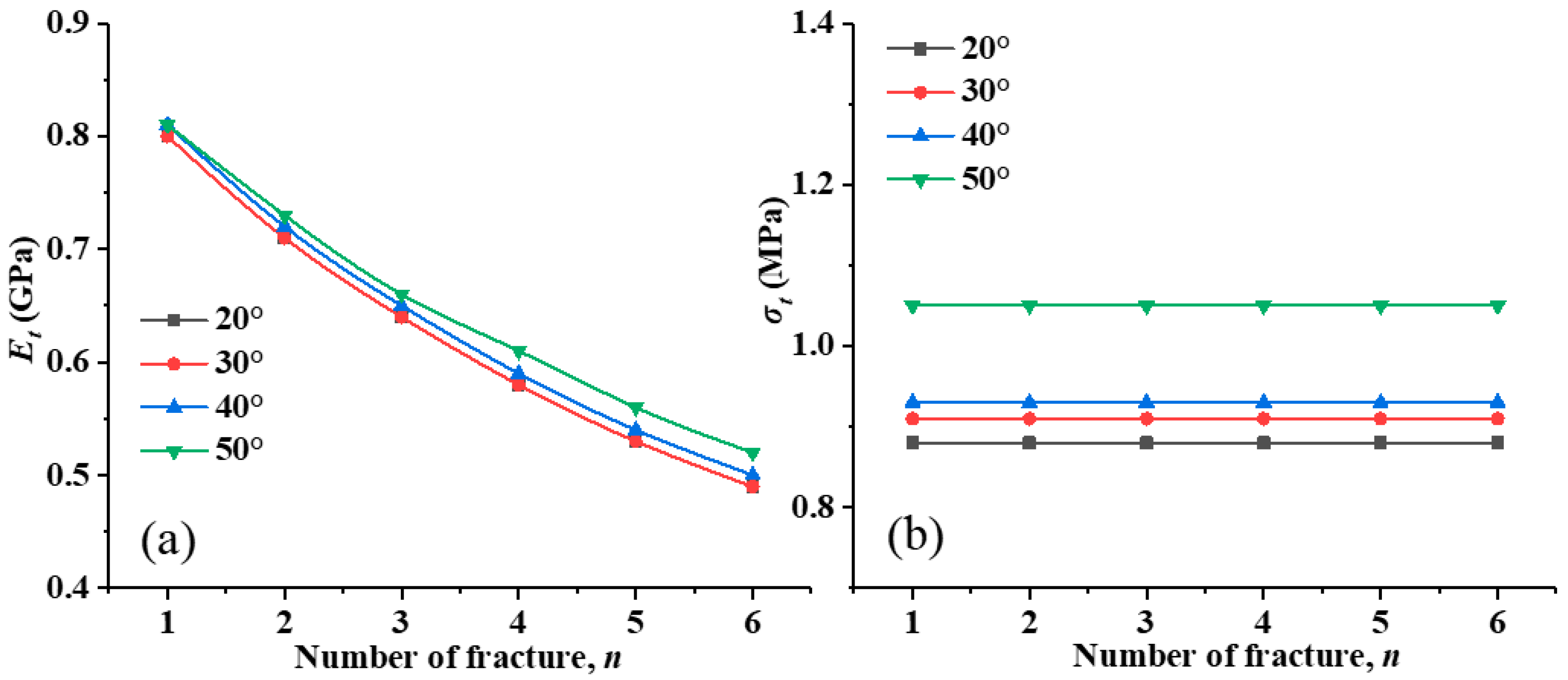
In cases of rock specimens with two joints, the effects of the perpendicular distance between the two joints (d), the angle between the joint and the horizontal direction (α) of parallel joints, and the joint density (n) on the complete stress–strain response were studied by numerical simulation. When d was kept constant at 10, 20, 30, and 40 mm, four different homogeneity indexes (α) were considered, which were 20, 30, 40 and 50°, respectively. Similarly, when α were kept constant, d was varied as 10, 20, 30, and 40 mm. Moreover, when d and α were kept constant, n was changed from 2 to 6.
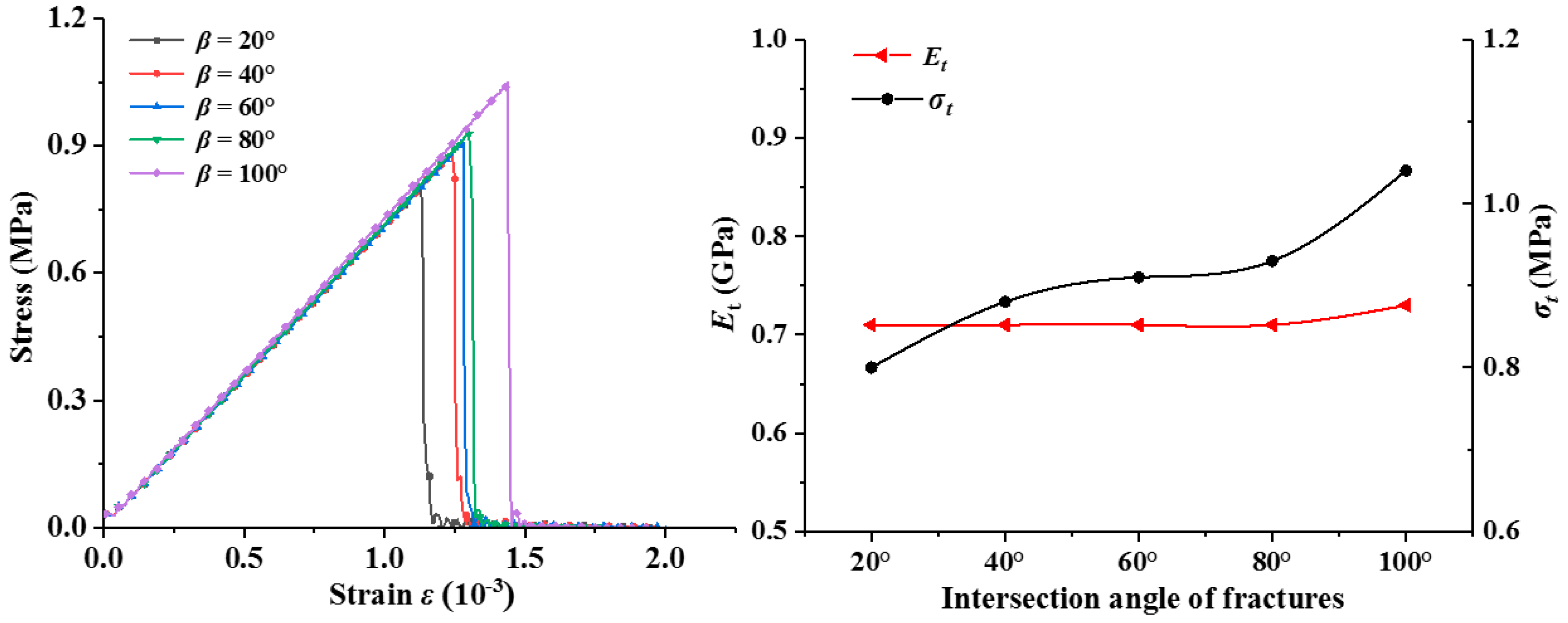
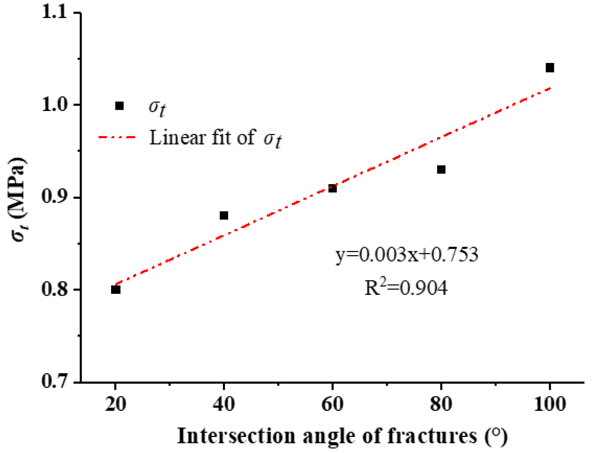
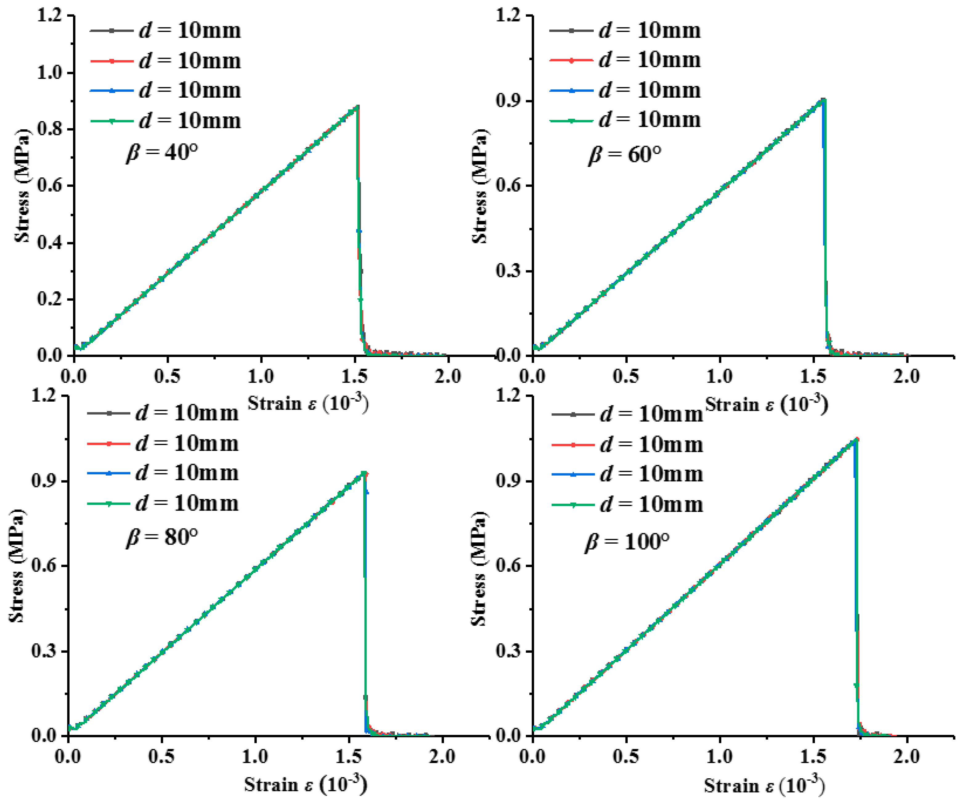
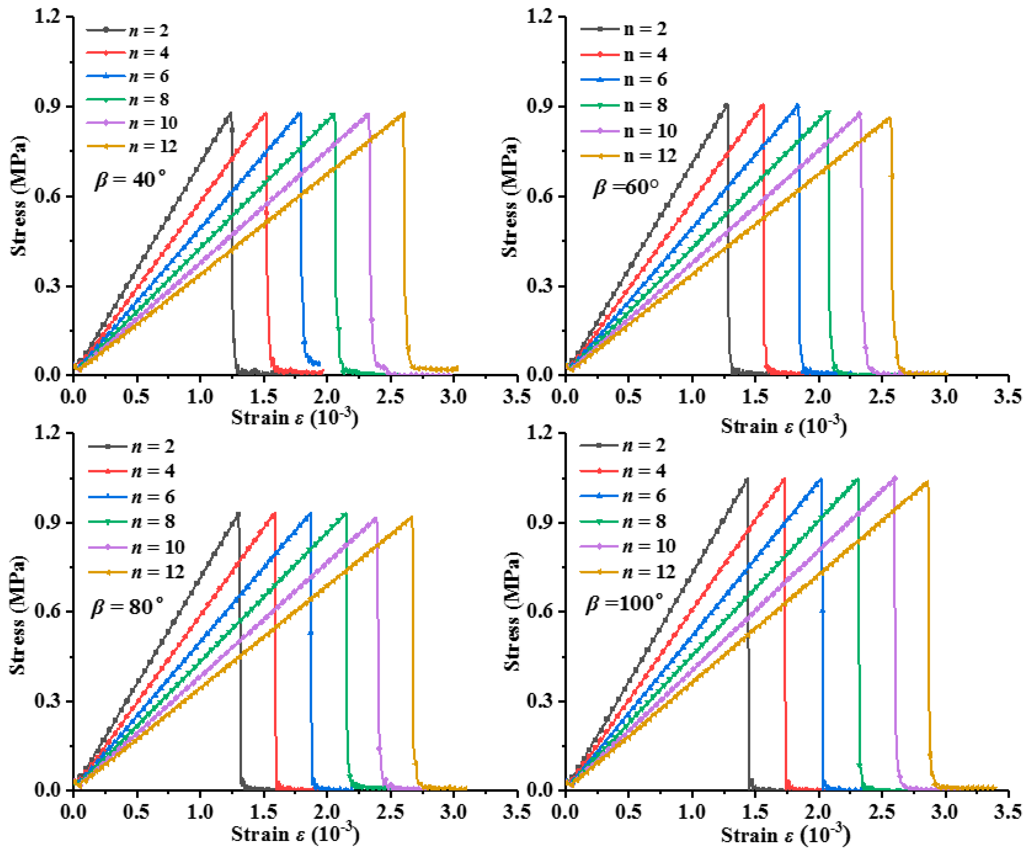
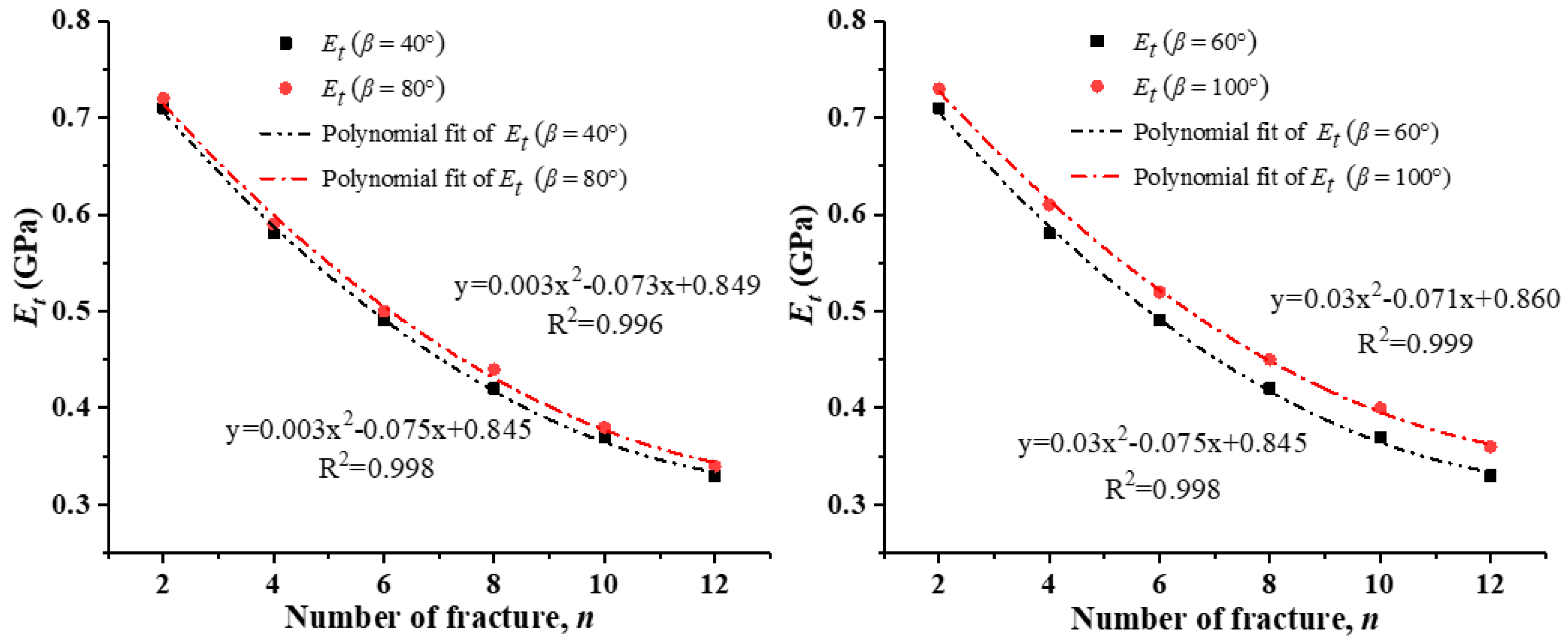
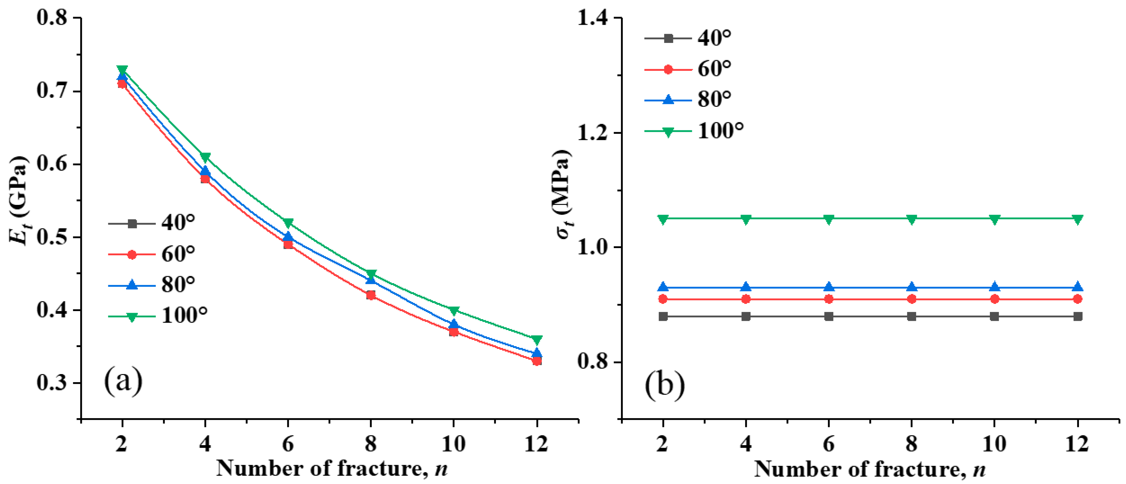
In cases of rock specimens with multiple joints, the effects of the perpendicular distance between the two cracks (d), the angle at which the two joints intersected (β), and the joint density (n) of intersecting joints on the complete stress–strain response were studied by numerical simulation. When d and n were kept constant as 0 mm and 2, there were six different homogeneity indexes (β) of 20, 40, 60, 80, and 100°. When β and n were kept constant, d was varied as 10, 20, 30, and 40mm. As a comparison, when d and n were kept constant, β was separately varied as 40, 60, 80, and 100°. When d and β were kept constant, n was changed from 4 to 12.
4. Discussion
The aforementioned results were obtained under the premise that joint development is not considered. In practice, joints will develop, and adjacent joints will connect and merge under mechanical loading. However, this study focuses on the effect of existing joints on the tensile properties.
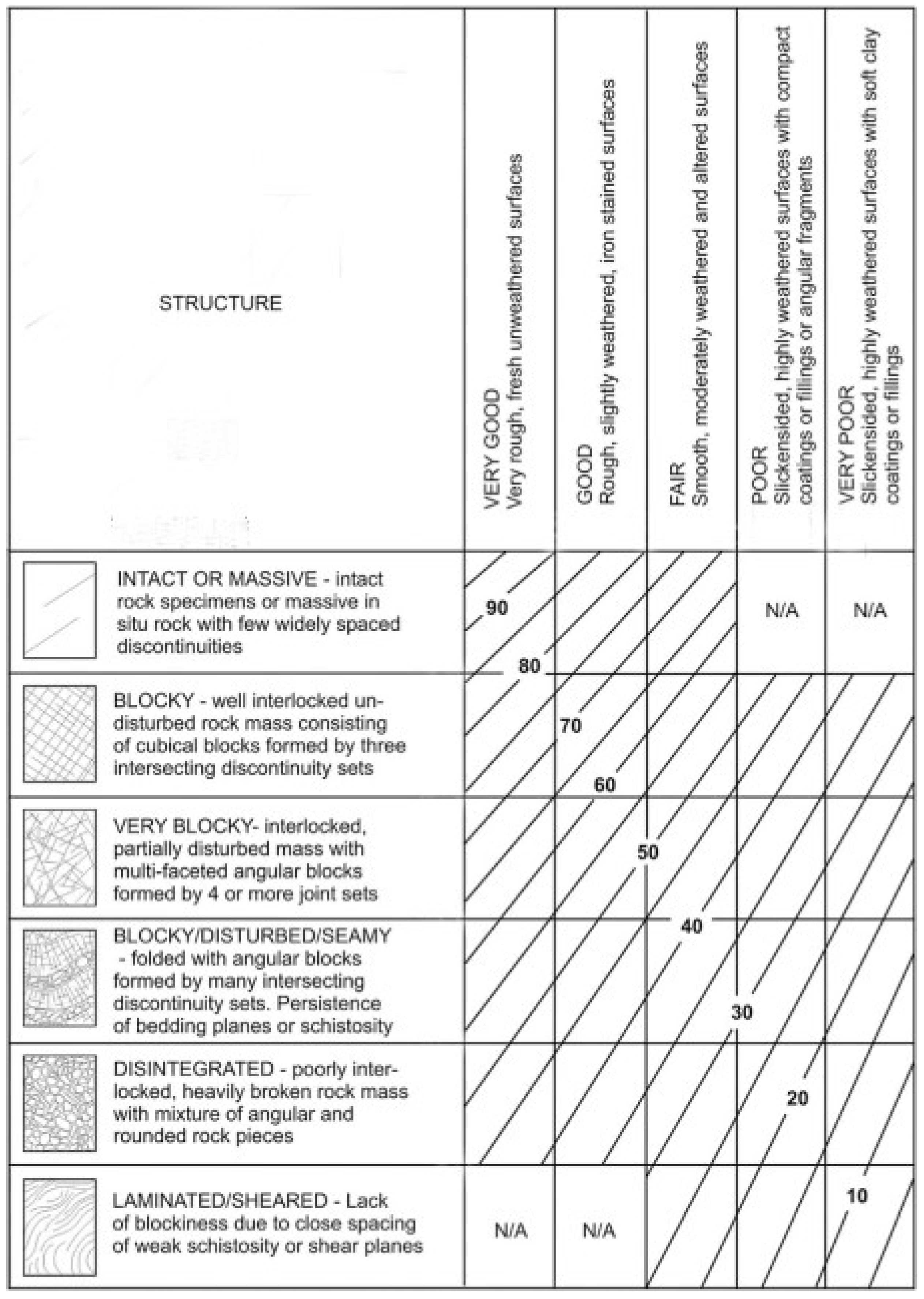
The change in the number of joints can be considered as a change in the degree of development of fractures of the rock mass. Then, the geological strength index (
GSI) is introduced [
10].
GSI is generally used to calculate the strength and Young’s modulus of a rock mass through laboratory rock mechanics properties and rock mass structural surface parameters.
Figure 17 [
38] is a
GSI quantization table based on rock mass structures and surface features of the structures.
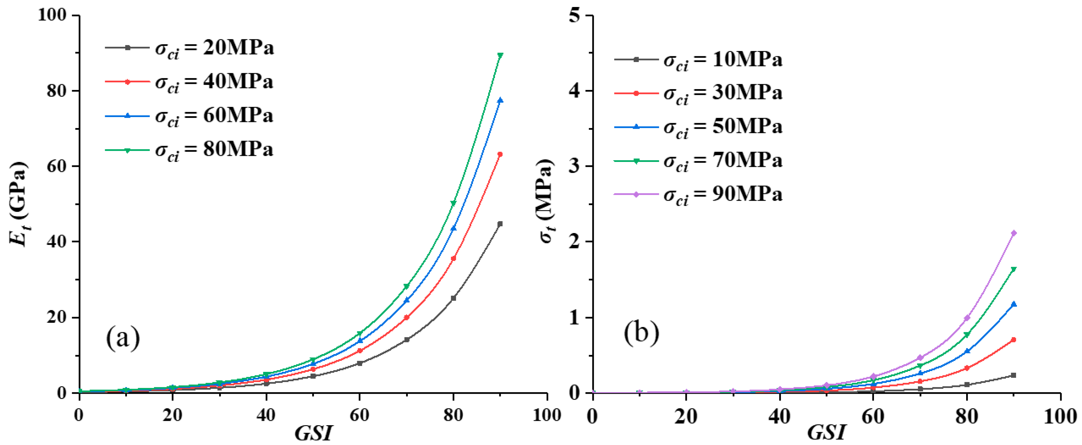
For rocks with a uniaxial compressive strength (
σci) < 100 MPa, the elastic modulus of a rock mass (
Et) is estimated from the following equation [
39]:
where
σci is the uniaxial compressive strength of intact rock, and
D is a factor that depends on the degree of disturbance to which the rock mass has been subjected by blast damage and stress relaxation. When
D = 0, the relationships between
Et and
GSI under the conditions of different values of
σci are shown in
Figure 18a. With the increase of the development of rock mass fissures, the Young’s moduli decline notably. The degradation patterns with the number of parallel and intersection joints are illustrated in
Figure 19a and
Figure 20a, respectively, which agree with the numerical results presented in the previous sections.
According to the generalized Hoek–Brown peak strength criterion [
40], the tensile strength of a rock mass is:
where
mb is the reduced value of the material constant
mi for the rock mass, and is given by:
and
s is the rock mass constants, given by:
When
D = 0, the relationships between
σt and
GSI under the conditions of different values of
σci are shown in
Figure 18b. In a certain interval, the influence on the tensile strength is negligible with the increase of the development of rock mass fissures. Then, the rationalities of the conclusion in this paper were proved, as illustrated in
Figure 19b and
Figure 20b.


