Abstract
In our previous study, intercritical quenching from the dual-phase region of ferrite and austenite regions, which is called lamellarizing (L) treatment, brought a clear improvement of balance between the strength and toughness of Cu-containing low alloy steel based on American Society for Testing and Materials (ASTM) A707 5L grade. Moreover, the results imply that the reverse transformation behavior during L treatment is very important in order to optimize the L treatment temperature. Hence, the purpose of this paper is to clarify the mechanism by which L treatment improves the mechanical properties in terms of reverse transformation behavior. Additionally, offshore structures require good weldability, because the structures generally have a lot of weld joints. Therefore, weldability was also investigated in this study. The investigation revealed that coarse Cu precipitates are observed in the not-transformed α phase, so the strength tendency in relation to the L treatment temperature is relevant to the area ratio of the not-transformed α phase and the transformed γ phase during L treatment. From the in situ electron back scatter diffraction (EBSD) results, it is believed to be possible to enhance the mechanical properties of Cu-containing low alloy steel by controlling the area ratio of the reverse-transformed gamma phase and selecting the appropriate L treatment temperature. Furthermore, the long part forging of Cu-containing low alloy steel has a good weldability, since the maximum hardness of the heat-affected zone (HAZ) is less than 300 HV, and the HAZ of steel has a good crack tip opening displacement (CTOD) property with less than 2.3 kJ/mm of heat input of GTAW.
1. Introduction
Oil and natural gas are major energy sources, accounting for about 60% of the primary energy in the world. Ultra-deepwater development is expected to increase in the future, as demands for oil and natural gas increase [1]. Copper-containing low alloy steel based on the American Society for Testing and Materials (ASTM) A707 5L grade is widely used for structural parts of offshore wells because of its low carbon equivalent (Ceq) and weld crack sensitivity composition (Pcm) [2,3,4]. From the viewpoint of preventing failure and accidents, steel with high strength and excellent low-temperature toughness is required. Generally, the forging steel is subjected to quenching (Q) and tempering (T). The steel is reverse-transformed from α to γ by holding the quenching temperature; after that, γ is transformed to bainite or martensite by water cooling. However, manufacturing large forged parts that have homogeneous and excellent properties over the whole length and thickness is difficult, since there are various reasons such as the segregation of elements, mass effects, and so on.
Therefore, in our previous research, we investigated the effect of intercritical quenching—which is called lamellarizing (L) treatment—from the dual-phase region of ferrite (α) and austenite (γ) on the mechanical properties and microstructures of A707 modified steel using 50-kg test ingots [5]. L-treated steels such as structural steel and steel for very low temperatures have been studied [6,7,8,9,10,11,12,13]. On the other hand, the effects of L treatment on Cu-containing low alloy steel have not been reported. The strength of Cu-containing low alloy steel is improved by Cu deposited during heat treatment [2,3,4,5,6,7,8,9,10,11,12,13,14]. Therefore, for the A707 modified steel, the Cu precipitation state is very important to obtain the strength. On the other hand, it has been reported that the precipitation behavior of Cu-bearing steel differs depending on each stage of the refining heat treatment, especially intercritical quenching or tempering [15]. So, it is extremely important to evaluate the mechanical properties of the material whose L treatment conditions are changed and also show the optimum treatment conditions in A707 modified steel as well in order to apply for offshore structures. In our previous research, L treatment brought clear improvement in the balance between the strength and toughness of A707 modified steel [5]. Therefore, the purpose of this research is to clarify the mechanism of improvement of mechanical properties by L treatment in terms of reverse transformation behavior, because the behavior during L treatment is considered to affect the mechanical properties of heat-treated steel due to grain refinement and the hardness of each phase. Based on our previous results, we applied L treatment to a long forged product about 20,000 mm long, and studied the mechanical properties, including crack tip opening displacement (CTOD) and nil ductility transition temperature (NDTT) over the trial production to check whether or not L treatment has a good effect on the mechanical properties.
In the manufacturing of offshore structures, the weldability of steel is very important because the structures have a lot of weld joints. In general, the equivalent amount of C is kept at a low level, and the component design is in consideration of the weldability of the A707 steel. However, since the element, such as C, Ni, and Mn, diffuses to the reverse-transformed γ phase during the L treatment and becomes concentrated locally [16], there is also a concern that the local non-uniformity of the element might reduce the weldability. Therefore, the weldability of the forging that applied L treatment was evaluated from the CTOD property of the welded part in this study.
2. Materials and Methods
2.1. Material
The specimens used in this study were cut from a 50-kg steel ingot made by vacuum induction melting (steel A) and a full-scale large forging that weighed approximately 10 metric tonnes (steel B). Table 1 shows the chemical composition and transformation temperatures of the steels. The steels are characterized by low C content to obtain good weldability, and high Ni and Cu content to guarantee adequate hardenability and strength. Moreover, Al and Nb are added to refine the prior austenite grain size.

Table 1.
Chemical composition and transformation temperature of the steels investigated.
Steel A was forged in the temperature range of 1523 K to 1173 K to a 45-mm thickness at a forging ratio of approximately 4.0 followed by air-cooling to room temperature. After that, normalizing and quality heat treatment with intercritical quenching were carried out. The heat treatment conditions are shown in Figure 1. The samples were quenched at 1173 K after normalizing at 1233 K, and L treatment was subsequently conducted at temperatures from 953 K to 1068 K in order to clarify the effects of L treatment temperature on the mechanical properties and its mechanism in terms of reverse transformation behavior. After L treatment, these were tempered at 873 K for 4 h. Since steel A is a forging plate of 45-mm thickness, the cooling rate of a center part of a water-quenched 300-mm thick section of the long part forging can’t be simulated by ordinary water cooling during quenching and L treatment. Since the difference in the cooling rate greatly affects the mechanical properties, it is necessary to control the cooling rate of quenching and L treatment for various investigations using steel A, which is a screening test for examining the applicability of L processing. Hence, in this research, the cooling rate of the test of steel A was simulated to be the central part of the water-quenched 300-mm thick section by the heat treatment furnace, which can control the rate.

Figure 1.
Heat treatment condition producing Q–L–T samples. Q: quenching; L: lamellarizing; T: temperature.
Figure 2 shows schematic illustration of the full-size product of steel B—which was 20,000 mm long, with a maximum diameter of 1200 mm and weight of 10 metric tons—and sampling locations. The production process is as follows: ingot making, hot working, and preliminary and quality heat treatment with L treatment at 1068 K. The casting ingot, which was 90 metric tons, was hot-forged to near the final product shape, as shown in Figure 3a. After forging, a quality heat treatment was conducted using a vertical furnace, as shown in Figure 3b.

Figure 2.
Schematic illustration of the long part product and sampling positions.
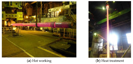
Figure 3.
Photographs of the manufacturing process.
2.2. Experimental Procedure of Mechanical Properties of the Steel with L Treatment
In this study, mechanical properties such as tensile strength, toughness, and fracture toughness were evaluated by a tensile test, Charpy impact test, drop weight test (DWT), and CTOD test. Following the ASTM E8 specification, cylindrical tensile test specimens 50 mm in gauge length and 12.5 mm in diameter were prepared such that the length direction of the specimen was perpendicular to the main forging direction. The Charpy impact test was conducted using 2-mm V-notched ASTM A370 specimens. The fracture appearance transition temperature (FATT) was also evaluated. The grain sizes (hereafter called the EBSD grain size, in which EBSD stands for electron back scatter diffraction) of the samples were estimated from the boundaries with misorientations of 15 degrees or larger determined by the analysis of EBSD patterns. The EBSD grain sizes and toughness have a correlation [3]. Thus, the EBSD grain size was measured from a cross-section of the Charpy impact test specimen in order to clarify the relationship between the L treatment temperature and the EBSD grain size.
The NDTT was measured by DWT in accordance with ASTM E208. The specimen type was P-3 with a crack starter bead. In addition, the CTOD test was carried out using the B × 2B and B × B types per ISO 15653:2010, as shown in Figure 4. The value of B was 16.7 mm for the B × 2B type specimen, and 100 mm for the B × B type specimen. The specimens were taken from the center of the forging. The CTOD tests for the B × 2B type thin series and B × B type thick series were conducted at 253 K and 273 K, respectively. The loading rate (dK/dt) was 0.5–3.0 MPa m1/2/s. CTOD values were calculated using Equation (1) [17]:
where δ (mm) is the CTOD value, K (MPa m1/2) is the stress intensity factor, E is Young’s modulus, rP is the rotation factor, W (mm) is the specimen width, a0 is the initial crack length, Vp (mm) is the plastic component of the notch-opening displacement, and z (mm) is the distance of the notch-opening gauge location on the surface of the specimen.
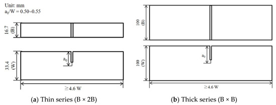
Figure 4.
Crack tip opening displacement (CTOD) specimen (three-point bending type) sizes of thin series (a) and thick series (b).
Moreover, Cu precipitation and the behavior of the reverse transformation was observed in this study to clarify the mechanism of the L treatment on the steel. Cu precipitation in the Q (hereafter called as-Q) and the Q-L (hereafter called as-L) material was observed using a transmission electron microscope (TEM). Moreover, reverse transformation behavior was checked using in situ EBSD, which was able to measure at high temperatures. The in situ EBSD test condition is shown in Figure 5. The reverse transformation behavior was researched at temperatures from 823 K (below AC1) to 1103 K (above AC3), as shown in Figure 5a, using the as-quenched sample of steel A. Moreover, the test was carried out at 1053 K and 1068 K for 2 h to clarify the relationship between the area ratio of these phases and the holding time of the L treatment (see Figure 5b).

Figure 5.
In situ EBSD test conditions of the evaluation of reverse transformation behavior (a) and change over time (b).
2.3. Experimental Procedure of Weldability of the Steel
The weldability was evaluated using welding test plates 250 × 400 × 20 mm in size, which were cut from the long part of the full-sized production forging. The test plates were welded using gas tungsten arc welding (GTAW) or submerged arc welding (SAW). Figure 6 and Table 2 show schematic illustrations of the welding test plate and welding conditions, respectively. The welding heat input was changed from 1.5 kJ/mm to 3.5 kJ/mm in order to investigate the relationship between heat input and mechanical properties, especially the toughness of the heat-affected zone (HAZ) for the weld joint. After welding, each specimen was cut from the weld test plate without preheating or post-weld heat treatment.

Figure 6.
Schematic illustration of welding test plate.

Table 2.
Welding conditions.
The macrostructures of the weld joints were observed using cross-sections of the joints. Specimens was cut perpendicularly to the welding direction and etched in a copper chloride ammonia and hydrochloric acid solution. The Vickers hardness profile was measured at 1-mm depth from the surface of the weld joints. In addition, the CTOD test was conducted in this study. The specimens for the CTOD test were B × 2B (15 × 30 mm) in accordance with BS 7448 Part 2, and the notch of the CTOD specimen was located at the center of the weld metal, which is called the fusion line (F.L.), as well as at F.L. + 1 mm, F.L. + 2 mm, and F.L. + 5 mm. After preparation of the specimen, local compression treatment was conducted according to BS 7448 Part 2 to introduce straight initial fatigue pre-cracking. Then, the test was carried out at 273 K.
3. Results and Discussion
3.1. Effect of L Treatment Temperature on Mechanical Properties
In our previous study [5], we investigated the mechanical properties of a Q–T sample and Q–L–T sample and the effect of L treatment temperature on the mechanical properties of the steel. The Table 3 shows a summary of the mechanical test data of the Q–T and Q–L–T samples for various L temperatures. Based on those results, the effects of L treatment on mechanical properties are as follows:

Table 3.
Summary of the mechanical test data of the Q–T sample and Q–L–T samples obtained at various L temperatures.
- The tensile strength (T.S.) of the Q–L–T sample is comparable to that of the Q–T sample. Also, 0.2% yield strength (Y.S.) is slightly decreased by L treatment.
- The toughness is dramatically improved by L treatment.
- The strength–toughness balance was obviously improved by L treatment at 1068 K (near the AC3 point of the steel).
Moreover, based on the above results, we investigated whether or not it is possible to obtain a good effect of L treatment on mechanical properties using a full-scale long forging product manufactured from A707 Grade L5 modified steel. The mechanical properties at each location are summarized in Table 4. From the above results, it was confirmed that the full-scale forging product was chemically homogeneous across its whole length, and had excellent tensile properties and fracture toughness using L treatment.

Table 4.
Typical production test results in a trial product.
These investigations clarified that L treatment is the better method to improve the mechanical properties of full-scale long forging products, but it is necessary to consider the mechanism. We considered that the effect of the L treatment temperature on the balance of strength and toughness depends on the ratio of the reverse transformed γ phase and the not-transformed α phases during L treatment. Therefore, the reverse transformation was investigated over a temperature range from below AC1 to above AC3 using in situ EBSD in order to clarify the microstructure variation during the treatment. The phase maps are shown in Figure 7. The gray region shown in Figure 7 indicates the not-transformed α phase, and the light yellow region indicates the reverse transformed γ phase at the measurement temperature. Figure 7a shows that all of the regions are in the α phase, and reverse transformation has not occurred, since 823 K—which is the measurement temperature—is about 100 K lower than the AC1 point of the steel. However, small amounts of reverse transformed γ phases were generated from the grain boundaries of the α phase at 903 K, and the reverse transformed γ phase region spread with increasing temperature. Furthermore, the insides of grains were observed at 1003 K. When the temperature was raised to 1053 K or 1083 K, there was a complicated structure consisting of not-transformed α phases and transformed γ phases. Over 1103 K, the microstructure consisted entirely of transformed γ phases. The in situ EBSD measurement results indicate that a fine and complicated microstructure is formed by L treatment at higher temperatures between AC1 and AC3. The complicated structure seems to indicate that the crystal grain after the L treatment become extremely fine.
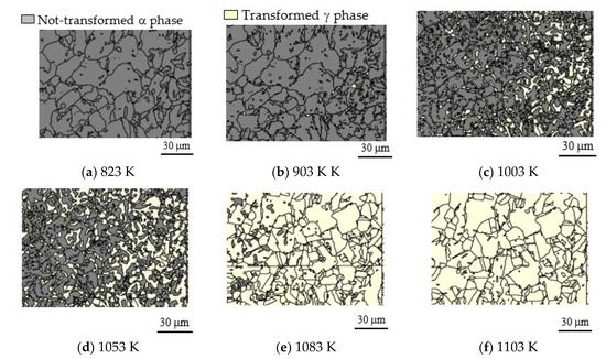
Figure 7.
Phase maps of not-transformed α phase and transformed γ phase at 823 K (a), 903 K (b), 1003 K (c), 1053 K (d), 1083 K (e), and 1103 K (f).
The area ratio of the transformed γ phase depends not only on the temperature of the L treatment but also on the holding time [8]. Hence, it is necessary to grasp the relationship between the γ phase and holding time to develop the mechanical property-improving effect due to the complication of the microstructure caused by the L treatment. Figure 8 shows changes with time in the area ratio of the not-transformed α phase and the transformed γ phase measured by in situ EBSD. The area ratios of the transformed γ phase when the temperature reached 1053 K and 1068 K were approximately 40% and 60%, respectively. At both temperatures, the proportion of the reverse transformation γ phase increased with the increase of the holding time, and the area ratio of the transformed γ phase reached approximately 60% at 1053 K and 90% at 1068 K after holding for 120 min. The area ratio of the γ phase at 1068 K also became almost constant beyond 100 min. Therefore, the necessary L treatment time is thought to be at least 100 min in order to stably obtain the mechanical property-improving effect.
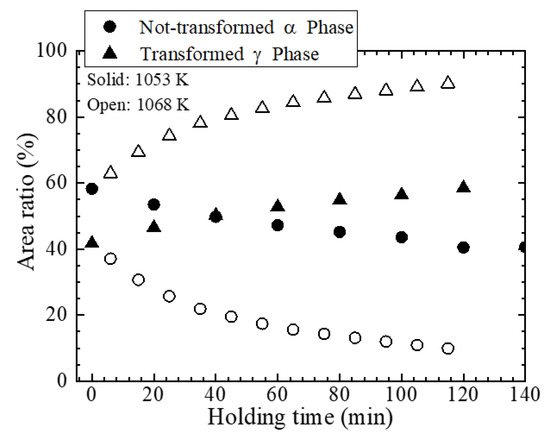
Figure 8.
Changes with time in the area ratio of the not-transformed α phase and the transformed γ phase during L treatment at 1053 K and 1068 K.
As mentioned above, the material is Cu precipitation-strengthened steel. Hence, it is important to elucidate the Cu precipitation behavior in the not-transformed α phase and in the transformed γ phase during L treatment. Figure 9 and Figure 10 show TEM images and element (Ni, Cu, and Mn) maps using TEM-Energy Dispersive X-ray Spectroscopy (EDS), respectively. No Cu precipitates were observed in the as-Q sample, while Cu precipitated significantly in the as-L sample. It should be noted that there are Cu precipitated region and non-precipitated regions. The region containing coarse Cu precipitates seems to be in the not-transformed α phase, because the α phase tempered at high temperatures during L treatment. On the other hand, the region containing no Cu precipitates is considered to be the transformed γ phase, and Cu may be dissolved in the matrix. The region at which coarse Cu precipitated is presumed to be the not-transformed α phase, because the not-transformed α phase is tempered during the L treatment, and the precipitated Cu is simply coarsened.
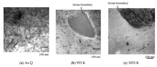
Figure 9.
TEM images of as-Q sample (a) and as-L sample heated to 953 K (b) and 1053 K (c).
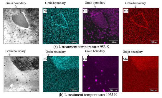
Figure 10.
Element mapping images of TEM-EDS of Q–L samples heated to 950 K (a) and 1053 K (b).
3.2. Mechanism of Improvement of Mechanical Properties by L Treatment
As mentioned above, the influences of the L treatment temperature on mechanical properties are as follows:
- The strength of the Q–L–T material becomes lower than that of the Q–T material in the cases where the L treatment was carried out in the temperature range from 1003 K to 1053 K (between AC1 and AC3).
- The toughness gradually improves as the L treatment temperature increases.
Firstly, we discuss the main reason for phenomenon (1). The strength of Cu-added steel generally depends on the dispersed state of Cu precipitation resulting from heat treatment [2,14], and the precipitated state is dependent on the L treatment temperature [15]. When the steel is heated to about 723 K to 823 K, the strength increases by age hardening, but the strength decreases in an overaging treatment at temperatures over 823 K. Additionally, L treatment is a heat treatment in the two phases (α and γ). The investigation implied that the not-transformed α phase is softened during L treatment, because it is heated up to 1068 K. Hence, the strength could be decreased in the softened not-transformed α phase. The results shown in Figure 9 and Figure 10 also indicate that the decreased strength is consistent with coarse Cu precipitates. On the other hand, Cu precipitates dissolve into transformed γ phases again, and then the γ phases are quenched. Hence, the γ phases harden due to Cu precipitation during tempering. L treatment at 953 K (right above AC1) has a trivial effect on the strength, because the not-transformed α phase was tempered at low temperatures. However, as the L temperature for treating the steel ranged between 1003–1053 K, the strength was notably decreased due to the not-transformed α phase treated with high-temperature tempering. For the L treatment at 1068 K (right below AC3), the strength of the sample was higher than that treated at approximately 1003 K to 1053 K. According to Figure 8, the transformed γ phase became the main phase after holding at 1068 K for 2 h; therefore, the harder phase inherited the γ phase, leading to improve strength.
Secondly, we discuss the main reason for phenomenon (2). Previous research has suggested that the retained γ phase is stabilized by L treatment and is helpful for enhancing the low-temperature toughness of the 9% Ni steel [6]. However, the Cu-containing low alloy steel did not have a retained γ phase after L treatment, so the improvement of toughness owing to the L treatment is not related to the retained γ phase for this steel. Therefore, it is necessary to verify the mechanism of toughness improvement other than the retained γ phase. Thus, we focused on the EBSD grain size that indicates the distribution of high angle grain boundary (HAGB), because the HAGB generally has high crack propagation resistance [18]. In other words, the refinement of EBSD particle size indicates an increase in the frequency of HAGB. The EBSD grain size of each sample underwent L treatment at a temperature range from 953 K to 1068 K in order to investigate phenomenon (2). The results are shown in Table 5 and Figure 11. The EBSD grain size became finer as the L treatment temperature increased, and also, the grain size of the sample treated at an optimized temperature, which was 1063 K, was the finest among the four samples. These results suggest that the toughness improvement with the increasing L temperature is due to the grain refining. Furthermore, in past literature [19], it is reported that the effective grain size corresponding to the destructive unit of the brittle fracture is refined, and the toughness is improved along with the refinement of the EBSD grain size. This report supports our results.

Table 5.
The electron back scatter diffraction (EBSD) grain size of Q–L–T samples treated at various temperature.
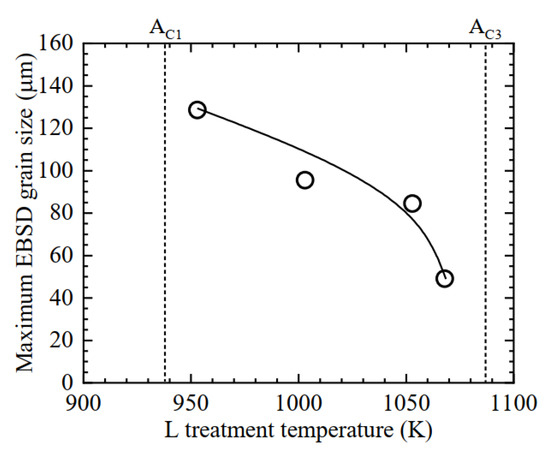
Figure 11.
Relationship between L treatment temperature and maximum EBSD grain size.
Reference [8] reported that the optimum L treatment of SA508 Gr.3 steel is at a relatively low temperature between the AC1 and AC3 of the steel, and the trend is different from the research results using A707 modified steel. In A707 modified steel, when the L treatment temperature is relatively high—that is, near the AC3 point—a good balance of strength and toughness could be obtained. This is considered to be the difference in whether the mechanical properties after the L treatment are due to the precipitation or dispersion of carbides, or the area ratio of the reverse transformed γ phase and the Cu precipitates. In the SA508 Gr.3 steel, the C content is about 0.20 mass%, and the carbides precipitated during the L treatment have an effect on the mechanical properties. On the other hand, the carbides might be slightly precipitated during the treatment in A707 modified steel, because the steel has 0.03 mass% C. Accordingly, the refinement of the grain size by reverse transformation during the L treatment and precipitation state of the Cu become dominant with respect to the mechanical properties. From these results, it is considered that the optimum L treatment condition differs depending on the steel type, because the influence factor affecting the mechanical properties is different.
Based on these results, schematic illustrations regarding changes in the microstructure and precipitates during the L treatment of A707 modified steel are shown in Figure 12. Reverse transformation does not proceed in the state at 953 K that is shown in Figure 12a, so the grain refining and the toughness improvement are not achieved. At 1053 K, as shown in Figure 12b, the toughness improves due to the refined grain size with the reverse transformation, but the strength is decreased by the not-transformed α phase containing coarse Cu precipitates, because the area ratio of the not-transformed α phase still remain approximately 40% after L treatment. At 1068 K, as shown in Figure 12c, the α phase almost transforms to the γ phase after 2 h. The transformed γ phase bears the strength of the steel, because it becomes fresh bainitic ferrite during the cooling process of L treatment, and furthermore, Cu precipitates in a matrix during tempering. It is important to retain a small amount of not-transformed α phase during L treatment for grain refining. From the above hypotheses, it is believed to be possible to enhance the mechanical properties of Cu-containing low alloy steel by controlling the area ratio of the reverse transformed γ phase and by selecting the appropriate L treatment temperature.
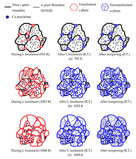
Figure 12.
Schematic illustrations of changes in microstructure and precipitates during L treatment at 953 K (a), 1053 K (b), and 1068 K (c).
3.3. Weldability of Cu-Containing Low Alloy Steel
The weldability of the steel was evaluated using a weld plate cut from near the top part (TP) of the full-scale forged product. The macrostructures of the cross-sections of the joints welded at 2.5 kJ/mm with SAW and 2.3 kJ/mm with GTAW are shown in Figure 13. No welding defects were observed in either macrostructure photo. Figure 14 shows the Vickers hardness distribution of each weld joint at 1-mm depth from the surface. Both weld joints had over-matching profiles, and also a maximum HAZ hardness of about 290 HV, which were acceptable values for offshore applications.

Figure 13.
Macrostructures of cross-sections of submerged arc welding (SAW) (a) and gas tungsten arc welding (GTAW) (b) weld joints.
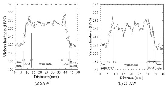
Figure 14.
Hardness profiles of the SAW (a) and GTAW (b) weld joints.
CTOD tests were performed at 273 K on five different notch locations of the SAW weld joint made under a heat input of 3.5 kJ/mm. The results are shown in Figure 15. The test load reached a maximum at the weld metal, F.L. + 2 mm and F.L. + 5 mm, and the CTOD values were judged to be δm. However, the CTOD value decreased approaching the F.L., and showed the lowest value at the F.L. The critical CTOD value was 0.06 mm at the F.L. location. An inverse pole figure (IPF) map with HAGB was measured at the F.L. and F.L. + 2 mm locations using EBSD in order to estimate the low CTOD value of the F.L. The results are shown in Figure 16. Fine grains were observed at the F.L. + 2 mm location, but there were coarse grains at the F.L. The temperature rise caused by welding probably leads to significant grain coarsening near the F.L. It is well-known that the toughness of the HAZ is decreased by the formation of coarse grain HAZ. Hence, it is important to reduce the heat input to the welded part, and suppress the grain coarsening in order to improve the toughness of the welded part.
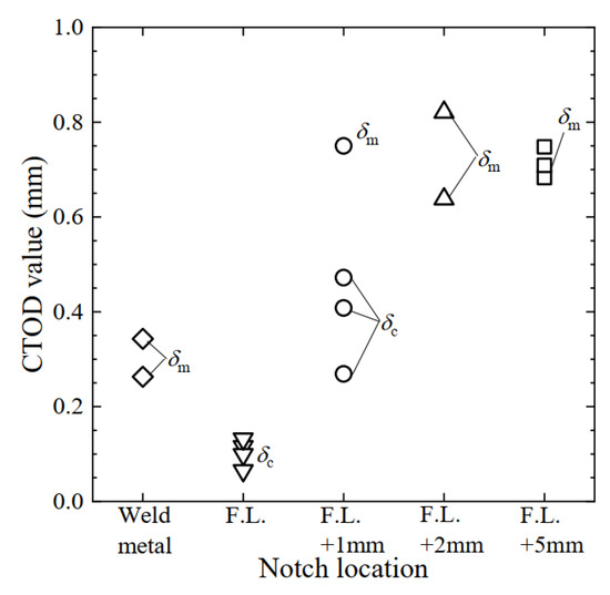
Figure 15.
CTOD test results at each location welded using SAW of 3.5 kJ/mm (test temp. 273 K).
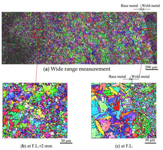
Figure 16.
Inverse pole figure (IPF) maps with HAGB (black line) of weld joint (a) at the fusion line (F.L.) + 2 mm location (b) and the F.L. (c).
Figure 17 shows the relationship between heat input and CTOD values at the F.L. of SAW or GTAW. For SAW, the CTOD values with a heat input of 2.5 kJ/mm were almost the same as those at 3.5 kJ/mm, but those of 1.8 kJ/mm were slightly higher than the other two. On the other hand, the CTOD properties were significantly improved with low-heat input GTAW. The critical CTOD values with heat inputs of 2.7 kJ/mm and 1.6 kJ/mm were 0.17 mm and 0.62 mm, respectively. The results suggest that the CTOD property has a tendency to improve with the decreasing heat input of the weld, and the tendency in GTAW was clearer than that in SAW. The difference between the SAW and GTAW results might be due to the shape of the HAZ, and we will work to clarify this in future studies. We have concluded that the long part forgings of Cu-containing low alloy steel have a good weldability, because the maximum hardness of HAZ is less than 300 HV, and the HAZ of steel has a good CTOD property with heat input less than 2.3 kJ/mm using GTAW.
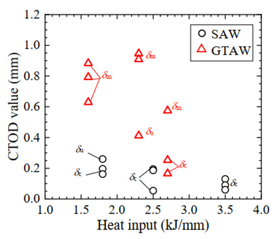
Figure 17.
Relationship between CTOD value and heat input for SAW and GTAW weld joint at F.L. (test temperature: 273 K).
4. Conclusions
The effects of L treatment temperature on the mechanical properties of A 707 Grade L5 modified steel were investigated, and the mechanisms of the effects were also discussed in terms of the reverse transformation behavior and precipitates. In addition, L treatment was applied to a full-scale long part product, and the weldability of the product was evaluated. In conclusion:
- The strength–toughness balance was obviously improved by L treatment at 1068 K (near the AC3 point of the steel), and an investigation of the mechanical and fracture toughness properties of the overall product revealed that L treatment resulted in high quality characteristics of the forging for use in an offshore structure.
- The in situ EBSD measurement results indicate that a fine and complicated microstructure is formed by L treatment at higher temperatures between AC1 and AC3. The complicated structure seems to indicate that the crystal grain after the L treatment become extremely fine. Moreover, it is clear that the necessary L treatment time is at least 100 min in order to stably obtain the mechanical property-improving effect.
- TEM–EDS analysis shows that coarse Cu precipitates are observed in the not-transformed α phase. Thus, the strengthening effect of the L treatment temperature is relevant to the area ratio of the not-transformed α phase and the transformed γ phase during L treatment. The strength, especially the Y.S., seems to be decreased by the not-transformed α phase acting as a softer phase.
- The EBSD results indicate that the improvement of toughness is due to the refining of the EBSD grain size by the transformed γ phase that is generated during L treatment.
- The long part forgings of Cu-containing low alloy steel have good weldability, since the maximum hardness of HAZ is less than 300 HV, and the HAZ of steel has a good CTOD property with less than 2.3 kJ/mm of heat input using GTAW.
Author Contributions
Y.H. and G.S. conceived and performed the experiments; Y.H. wrote the paper; K.H. reviewed and supervised the work.
Funding
This research received no external funding.
Conflicts of Interest
The authors declare no conflict of interest.
References
- Saint-Marcoux, J.; Legras, J. Impact on Risers and Flowlines Design of the FPSO Mooring in Deepwater and Ultra Deepwater. In Proceedings of the Offshore Technology Conference 2014, OTC, Texas, 5–8 May 2014; 2014; pp. 946–956. [Google Scholar]
- Martin, A.; Walsh, S.P. The Chemistry Modifications to ASTM A707 for Offshore Structural Integrity. In Steel Forgings Second Volume; ASTM International: Pennsylvania, 1997; pp. 196–209. [Google Scholar]
- Venturino, P.; Otegui, L.J.; Teutónico, M. GAS Pipeline Leakage in Urban Subsurface Soil. Procedia Mater. Sci. 2012, 1, 289–296. [Google Scholar] [CrossRef]
- Papavinasam, S. Corrosion Control in the Oil and Gas Industry, Chapter3: Material; Elsevier: Amsterdam, The Netherlands, 2014; pp. 133–177. [Google Scholar]
- Honma, Y.; Sasaki, G.; Hashi, K. Improvement on Mechanical Properties of Cu-Containing Low Alloy Steel of Long Part Forging for Offshore Applications by Manufacturing Process. In ASME 2017 36th International Conference on Ocean, Offshore and Arctic Engineering; American Society of Mechanical Engineers: Trondheim, Norway, 2017. [Google Scholar]
- Saitoh, N.; Yamaba, R.; Muraoka, H.; Saeki, O. Dvelopment of Heavy 9% Nickel Steel Plates with Superior Low-Temperature Toughness for LNG Storage Tanks. Nippon Steel Tech. Rep. 1993, 58, 9–16. [Google Scholar]
- Shikanai, N.; Mitao, S.; Endo, S. Recent Development in Microstructural Control Technologies through the Thermo-Mechanical Control Process (TMCP) with JFE Steel’s High-Performance Plates. JFE Tech. Rep. 2008, 11, 1–6. [Google Scholar]
- Kim, H.; Ahn, Y.; Oh, Y.; Kim, G.; Hong, J. Effect of Intercritical Annealing on the Toughness and Strength of SA508 Gr.3 Heavy Section Forging Steel. In Proceedings of the 13th Internatinal Forgemasters Meeting, Pusan, Korea, 12–16 October 1997; pp. 197–208. [Google Scholar]
- Xie, B.S.; Cai, Q.W.; Yun, Y.; Li, G.S.; Ning, Z. Development of high strength ultra-heavy plate processed with gradient temperature rolling, intercritical quenching and tempering. Mater. Sci. Eng. A 2017, 680, 454–468. [Google Scholar] [CrossRef]
- Tsuchiyama, T.; Inoue, T.; Tobata, J.; Akama, D.; Takaki, S. Microstructure and mechanical properties of a medium manganese steel treated with interrupted quenching and intercritical annealing. Scrip. Mater. 2016, 122, 36–39. [Google Scholar] [CrossRef]
- Yan, N.; Di, H.; Misra, R.D.K.; Huang, H.; Li, Y. Enhancing austenite stability in a new medium-Mn steel by combining deep cryogenic treatment and intercritical annealing: An experimental and theoretical study. Mater. Sci. Eng. A 2019, 753, 11–21. [Google Scholar] [CrossRef]
- Thompson, S.W. Fine–scale structural features of intercritically aged HSLA-100 plate steel and their influence on yield strength and low-temperature impact toughness. Mater. Charact. 2018, 136, 425–434. [Google Scholar] [CrossRef]
- Hwang, B.; Lee, G.G. Influence of thermomechanical processing and heat treatments on tensile and Charpy impact properties of B and Cu bearing high-strength low-alloy steels. Mater. Sci. Eng. A 2010, 527, 4341–4346. [Google Scholar] [CrossRef]
- Takaki, S.; Fujioka, M.; Aihara, S.; Nagataki, Y.; Yamashita, T.; Sano, N.; Adachi, Y.; Nomura, M.; Yaguchi, H. Effect of Copper on Tensile Properties and Grain-Refinement of Steel and its Relation to Precipitation Behavior. Mater. Trans. 2004, 7, 2239–2244. [Google Scholar] [CrossRef]
- Han, G.; Xie, Z.J.; Li, Z.Y.; Lei, B.; Misra, R.D.K. Evolution of crystal structure of Cu precipitates in a low carbon steel. Mater. Design 2017, 135, 92–101. [Google Scholar] [CrossRef]
- Wei, R.; Enomoto, M.; Hadian, R.; Zurob, H.S.; Purdy, G.R. Growth of austenite from as-quenched martensite during intercritical annealing in an Fe–0.1C–3Mn–1.5Si alloy. Acta Mater. 2013, 61, 697–707. [Google Scholar] [CrossRef]
- International Organization for Standardization. ISO 15653; International Organization for Standardization: Geneva, Switzerland, 2010. [Google Scholar]
- Gourgues, A.F.; Flower, H.M.; Lindley, T.C. Electron Backscattering Diffraction Study of Acicular Ferrite, Banite, and Martensite Steel Microstructures. Mater. Sci. Technol. 2000, 16, 26–40. [Google Scholar] [CrossRef]
- Hanamura, T.; Yin, F.; Nagai, K. Ductile-Brittle Transition Temperature of Ultrafine Ferrite/Cementite Microstructure in a Low Carbon Steel Controlled by Effective Grain Size. Iron Steel Inst. Jpn. Int. 2004, 44, 610–617. [Google Scholar] [CrossRef]
© 2019 by the authors. Licensee MDPI, Basel, Switzerland. This article is an open access article distributed under the terms and conditions of the Creative Commons Attribution (CC BY) license (http://creativecommons.org/licenses/by/4.0/).