1. Introduction
Surface plasmons (SPs) are waves that result from the collective oscillations of electrons excited by electromagnetic waves at a metal/dielectric interface, propagating along the metal surface and evanescently confined in the perpendicular direction [
1,
2,
3,
4,
5,
6]. SP waves have local confinement characteristics, and their distribution depths are smaller than the wavelength order, i.e., beyond the diffraction limit [
2,
7], making SPs a great candidate for use in the production of sub-wavelength optoelectronic devices [
8,
9,
10,
11,
12]. By controlling the propagation of SPs at the nanoscale, functions such as focusing and trapping nanoparticles at a much lower intensity level can be achieved [
13,
14]. In conventional optics, however, this is not possible, because of the limitations of the diffraction limit, and the trapping force drops quickly as the radius of the particle decreases due to reduced gradient force [
15], so the excellent performance of this beyond-the-diffraction-limit technology is used fully to design SP lenses [
16,
17,
18] and plasmonic trapping devices [
19]. The Archimedes spiral lens gives incident light an additional geometric phase for different handedness [
20,
21,
22,
23], and the light field will thus exhibit different functions for particle trapping or particle rotation [
14,
24,
25]. In contrast to the traditional 2D plasmonic Archimedes spiral lens (PASL), the Archimedes spirals were engraved on a planar gold film, and a focusing spot or plasmonic vortex can only be formed by constructive interference on the gold film surface when the distance between the two spirals is equal to the surface plasmon polariton (SPP) wavelength. This greatly reduces flexibility for practical applications of these PASLs, such as manipulation of biological cells [
26] and stretching of DNA [
27,
28].
In this work, a single three-dimensional (3D) PASL has been investigated by finite element method (FEM). By controlling the angular momentum of the plasmonic near-field directly, a focusing spot or a plasmonic vortex field can be formed in the central hollow of the 3D PASL. We study the effects of several parameters, such as the initial spiral radius
r0, the horizontal distance between successive turns of the spiral
gap and the height of the structure
h0, on the focusing spot/plasmonic vortex position and the focusing intensity in detail. We find that the focusing spot/plasmonic vortex position can only be adjusted by varying the height of the structure. It should be noted that our 3D PASL is free from the rigid structural constraint of the adjacent helical spiral pitch that is included in the 2D PASL for the sake of constructive interference. This makes our designed 3D PASL structure much more flexible, and it offers greater potential than the 2D PASL for many practical applications, including micromechanical systems, optofluidic devices, microbiology and biomedical photonics, particularly in the analysis of conformational changes in DNA or proteins by providing controllable trapping or a controllable local vortex turbulence [
29].
2. Plasmonic Archimedes Spiral Lens
Normally, the geometry of an Archimedes spiral (AS) is expressed using polar coordinates as , where r is the distance from the AS to the origin O, r0 is the initial spiral radius, ϕ is the azimuthal angle in radians, and gap represents the horizontal distance between successive turns of the spiral. Here, we extrude the two-dimensional Archimedean spiral into three dimensions along the z-axis using the relation , where h0 is the rise height of the 3D AS when ϕ grows by . Obviously, if h0 = 0, then the 3D structure reverts to its 2D counterpart.
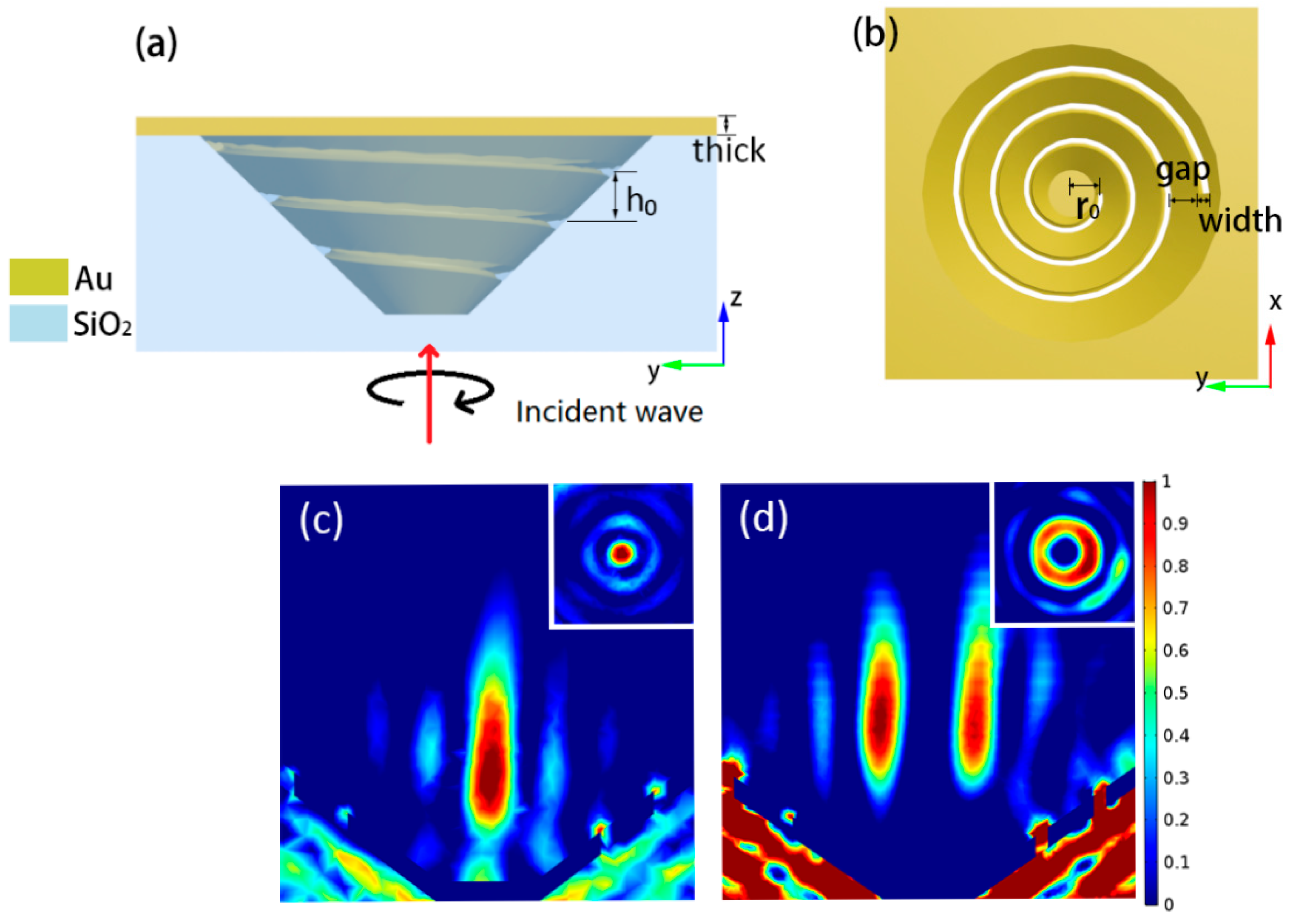
In this manuscript, we design a 3D PASL, as shown in
Figure 1. The 3D PASL is fabricated on a silicon dioxide substrate that has a funnel-shaped depression, which is plated with a 300-nm-thick gold film. A 3D Archimedes spiral slot is then engraved by swirling on the inner sidewall of the funnel-shaped gold film. Please note that both the bottom of the silicon dioxide substrate and gold film are closed to avoid the directly transmitted light interfering with the plasmonic field. The ambient medium in the funnel and above the gold film is buffer solution (such as phosphate buffer saline, abbreviated PBS, a water-based pH-adjusted blend of ultrapure-grade phosphate buffers and saline solutions. The contents of PBS buffer are determined by the requirements of concentration of salt in the buffer and pH in practical application. The pH of most common composition of PBS is ~7.4.), which is feasible to represent the real cell trapping environment. The slot is approximately 200 nm wide and starts at
r0 = 1.4 µm, with its azimuthal angle
ϕ ranging from 0 to
, i.e., the completed helix has three turns.
When the circularly polarized light propagating along the
z-axis illuminates the 3D PASL from the bottom of the SiO
2 substrate, the incident light wave is coupled to the SPP modes at the entrances to the AS slot. SPPs, as evanescent waves, propagate along the radial direction, either inwards or outwards, to the center of the PASL. Because of the decoupling effect of the 3D spiral slots, some of the SPPs are scattered into free space and are then converted into propagating waves when they encounter other out-of-plane spiral grooves. This is the main point by which our 3D polycyclic AS structure is quite different from its 2D counterpart. These propagating waves interfere and produce high-intensity focal spots or plasmonic vortices at the center of the structure, as shown in
Figure 1c,d, which will be discussed in the next section.
In this paper, the optical excitation of this PASL involves the use of left-hand or right-hand circularly polarized plane waves, which carry spin angular momentum
s = 1 or
s = −1, respectively. Because of the complexity of the three-dimensional structure, we changed the traditional two-dimensional Archimedes spiral electric field distribution equation [
30] and we only study the electric field distribution on the central axis of the funnel. When illuminated by light with left-hand circular polarization, the SP field generated along the
z-direction on the central axis of the structure can be expressed in cylindrical coordinates as:
Here, h represents the height of a specified point A on the central axis of the structure, kspp is the wavenumber of the generated SPP, is the distance from a point on the spiral slot to the point A on the central axis of the structure, and is the wavelength of the incident light in the SiO2. kspp.cosθ is a component of the SPP wave vector and is the additional phase caused by the increase in the spiral’s height. Using the above equation, we can obtain the relationship between h0 and the focal length, and we find that the focal length also increases when h0 increases within a specific range.
To enable convergence and focusing of a scattering field using the polycyclic AS structure, the relationship between the structural parameters and the additive phase difference must satisfy the following equation: , where is the increment in distance between two points on the spiral slot relative to the focal point, and is the additive phase difference between these two points on the spiral. The phase difference consists of two parts; one is the geometric phase that is caused by the AS itself, and the other is simply caused by the rise in height of the 3D spiral that is equal to , where is the height increment between the two points on the spiral. Obviously, when is equal to the difference in distance between the spiral slot and a point at the center of the structure, a focal point will be generated.
3. Simulations and Discussion
To verify the performance of the proposed 3D PASL, finite element method (FEM) simulations are performed using Comsol Multiphysics 5.2a software. In our simulation, the power of the incident light is 80 mw, the free space wavelength of the incident light is 1310 nm and the dielectric constant of gold at this wavelength is
= −68.53 + 7.4542i [
31]. Consequently, the wavelength of the SPP that is launched at the Au-PBS interface is
λspp = 969nm, which is calculated from
, where
represents the real part of
and the dielectric constant of the ambient PBS buffer solution is
= 1.7408.
The above equations for the 3D AS indicate that the main factor that affects the focal length of the proposed 3D structure is the rise height h0 of the 3D PASL, which can be expected to influence the generated SP near-field. Therefore, we focus here on discussing the effects of this factor on the focal length under excitation by light with left-hand circular polarization.
Through numerical analysis, we found that, compared with parameters such as
gap and
r0,
h0 has the most obvious effect on the focal length. We therefore fixed the parameters
gap,
r0 and
width at 800 nm, 1400 nm and 200 nm, respectively, and then gradually changed the rise height
h0 between successive turns of the spiral from 575 nm to 725 nm in steps of 50 nm.
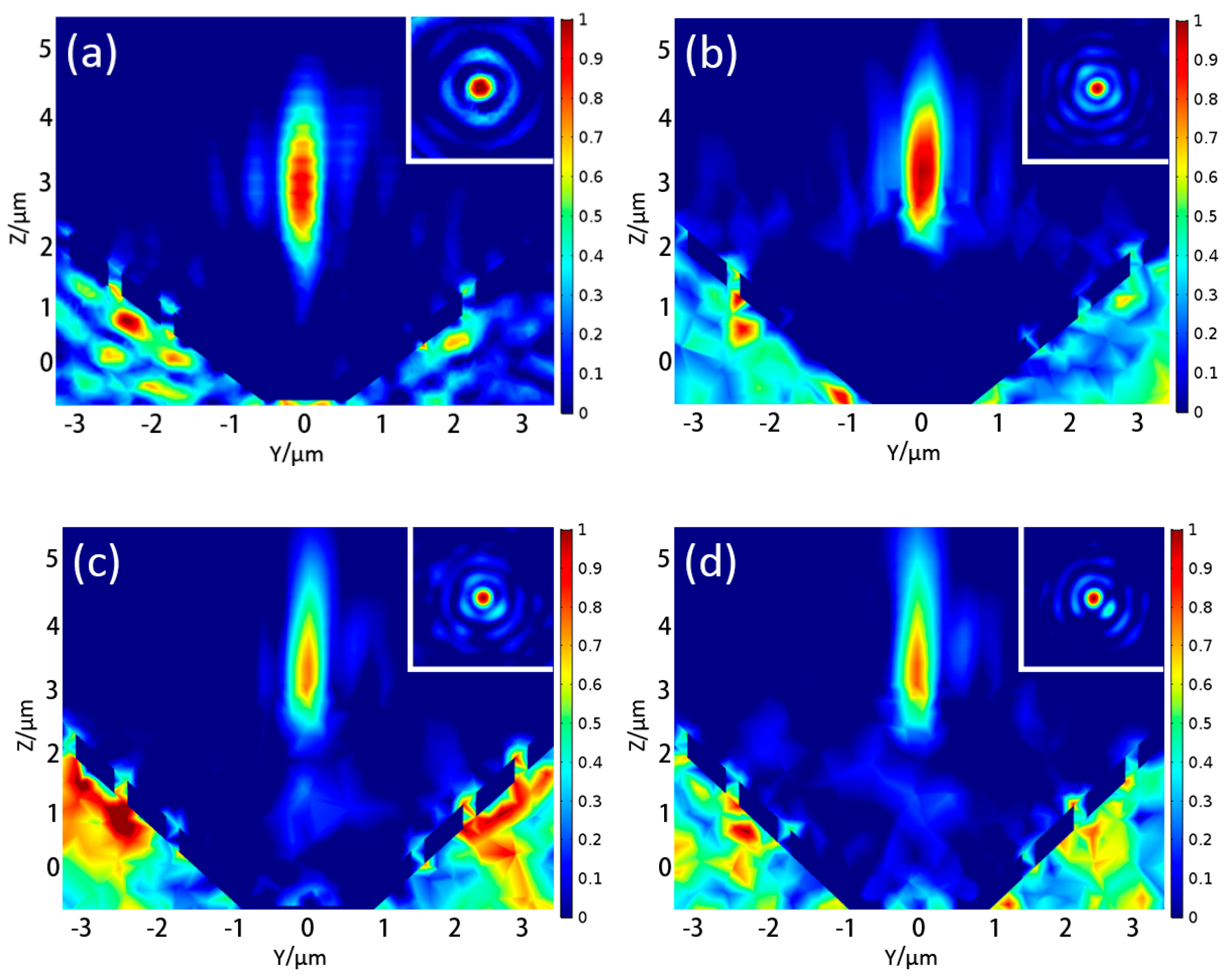
Figure 2a–d shows the intensity distributions (|E|
2) for different
h0 values under illumination by incident light with left-hand circular polarization. It was found that the focus position floats above the funnel shape and moves further from the bottom of the funnel with increasing
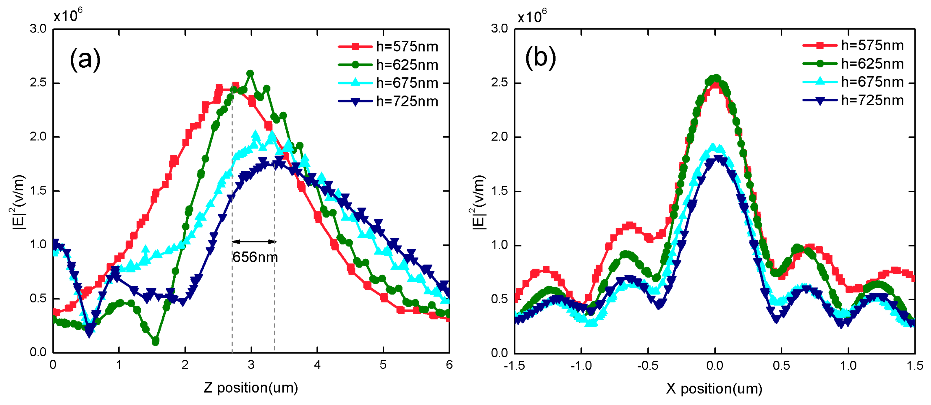
h0. Because the 3D spiral groove rises simultaneously, this also causes the focus to rise. Unlike its counterpart 2D structure composed of three concentric annular rings, a slight asymmetry in the intensity is expected to be observed when the damping of the SPP in both media and the unequal propagation distances from the spiral slot to the focus over the different azimuthal angles are taken into account. The focusing characteristics of the 3D PASL are depicted in
Figure 3. The figure shows that the focal length is elongated by 656 nm (from 2765nm to 3421 nm) when
h0 increases by 150 nm.
Figure 3b indicates that there is no obvious change in the value of the full width at half maximum.
When the type of incident light is switched to plane waves with right-hand circular polarization, a plasmonic vortex field is generated around the origin of the structure that fits the second Bessel function of the first kind, as shown in
Figure 4. In addition, when
h0 changes, the position of the plasmonic vortex varies with a similar trend to that of the focus under excitation by light with left-hand circular polarization. This longitudinal parameter
h0 thus makes the 3D PASL more flexible and the focal point or plasmonic vortex can therefore be adjusted in the longitudinal direction. As a result, the proposed 3D PASL is capable of creating a multi-functional application that will represent an aggressive expansion from the capabilities of the 2D PASL.
We also investigate the feasibility of trapping and rotation of microparticles using the 3D PASL, as compared with the feasibility of using the previous 2D PASL. It is assumed that the microparticle to be used is a polystyrene sphere with a diameter of 1 µm that is lying on the focal plane. Because of the three-dimensional structure of the PASL, we also analyzed the optical force acting in the z-direction, which helps to overcome the problem of particle manipulation on the surface when using the 2D PASL. The Maxwell stress tensor is used to calculate the optical force (F) and the optical trapping potential based on Equations (2)–(4) below. An integral stress tensor is applied over the entire spherical surface to obtain the optical force acting on the microsphere. The optical trapping potential is given by integrating the optical force acting on the microsphere along a specific direction.
Here,
n is the unit vector in the normal direction of the closed surface that surrounds the target space. When the sphere moves on the
x-axis in the focal plane, the optical forces that are exerted on the microsphere in the
x-direction (
Fx) and the
y-direction (
Fy) are as shown in
Figure 5a. Obviously,
Fx is much stronger than
Fy, and
Fx plays a major role in pulling the microsphere back towards the center of the focus. When the sphere moves on the
y-axis in the focal plane,
Figure 5c indicates that the optical force exerted on the microsphere in the
y-direction (
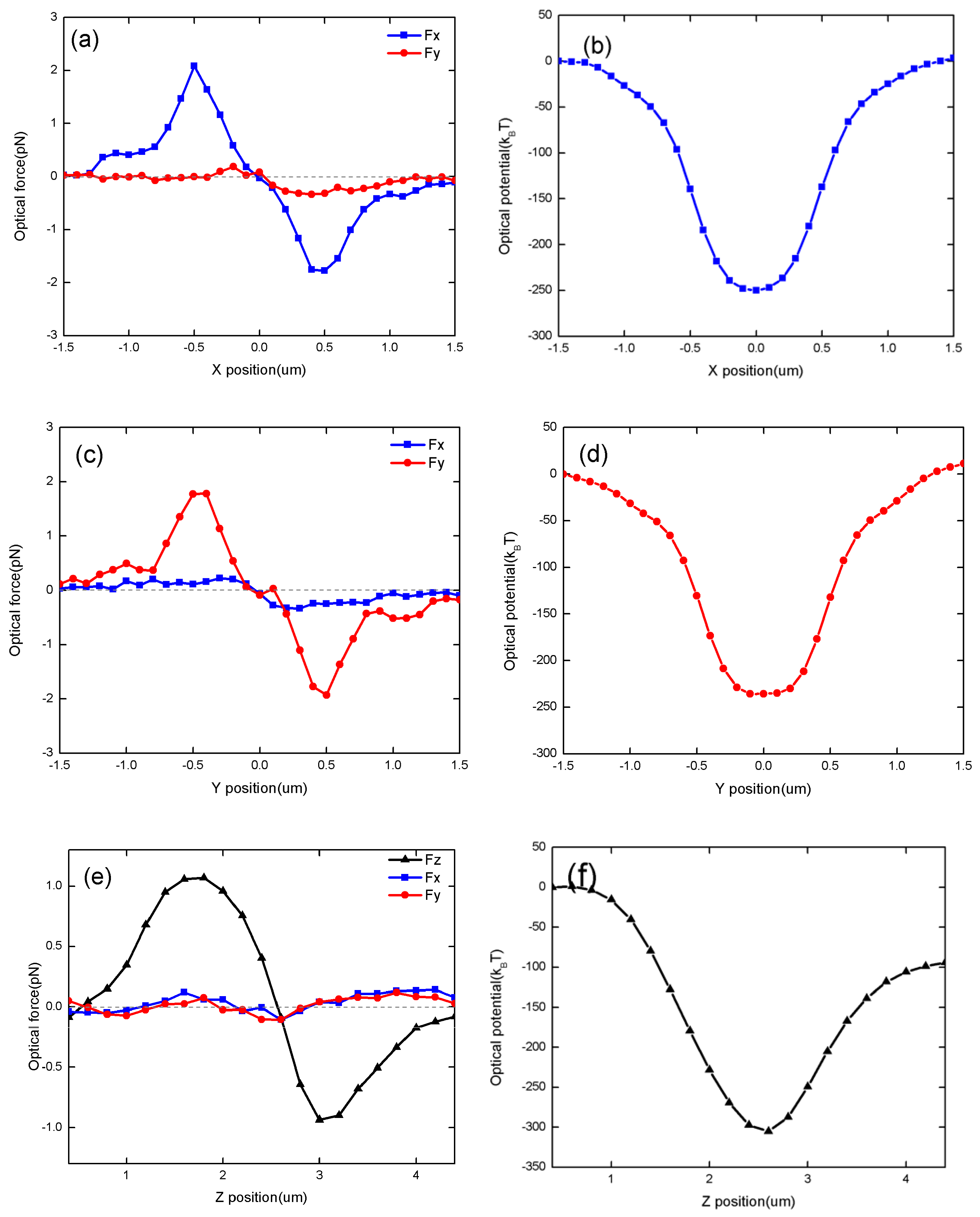
Fy) plays a major role and also pulls the microsphere back towards the center of the focus. In the vertical direction, as shown in
Figure 5e, when the microsphere is below the focal point, the optical force that is exerted on the microsphere is positive along the
z-axis, while the optical force that is exerted on the microsphere is negative along the
z-axis when the microsphere is located above the focal point; this also means that the stable position of such a 1-µm-diameter microsphere is the focus. These results are consistent with the principle of optical tweezers, in either the lateral focal plane or the vertical focal plane. The calculated trapping potentials in the
x-direction and the
y-direction are shown in
Figure 5b,d, respectively. Normally, we consider 10
kBT as the threshold for stable optical trapping [
15], where
kB is the Boltzmann constant and
T is the thermodynamic temperature. We can show here that the potential well is about 250
kBT in depth, which means that the formed plasmonic focus can capture a polystyrene sphere with a diameter of 1 µm stably when the power of the incident light is 80 mw. So conventional lasers can generate sufficient optical force for stable optical trapping.
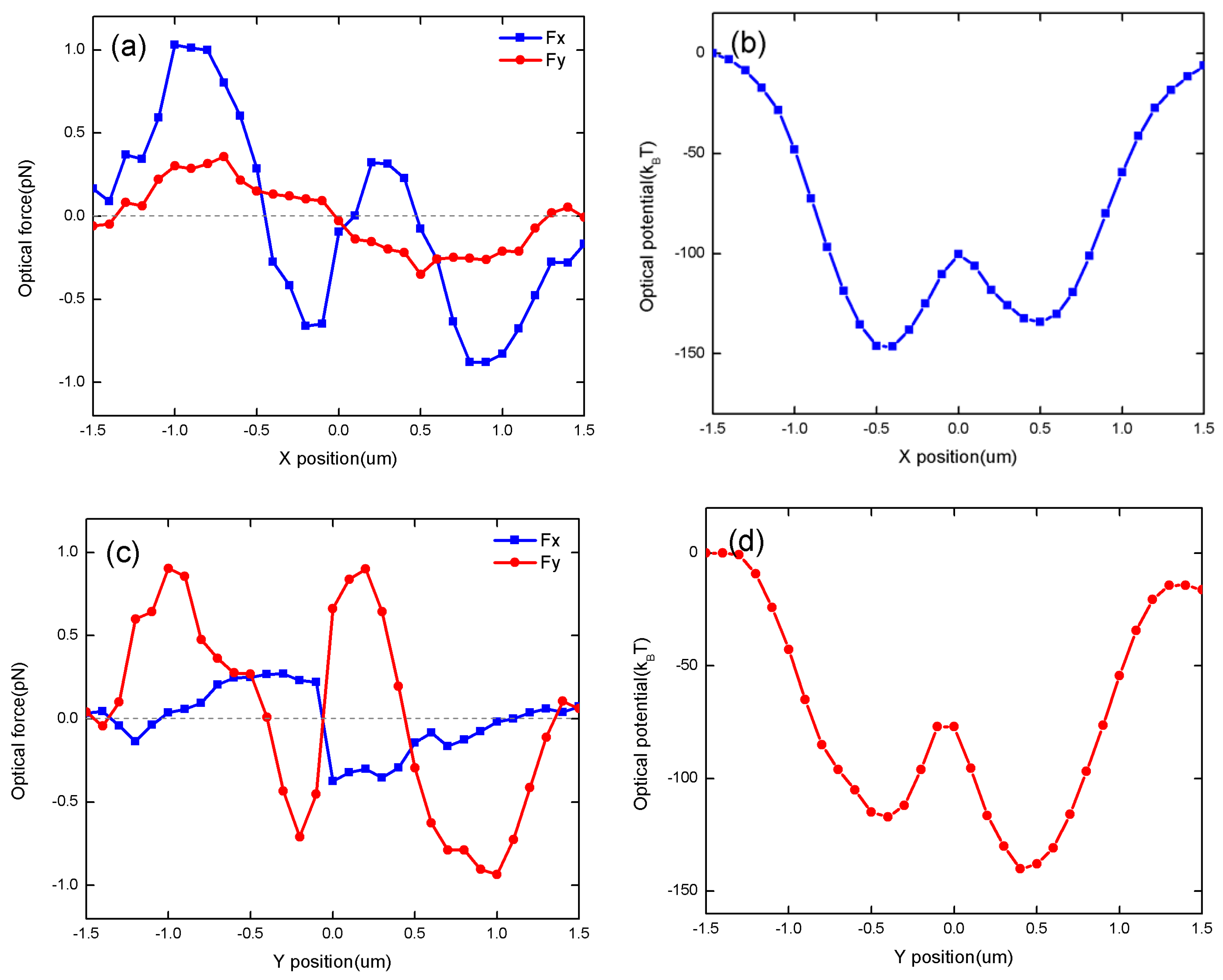
Next, we change the incident light to a right-hand circularly polarized plane wave and calculate the resulting optical force and potential. When a 1-µm-diameter microsphere leaves the origin to travel from −1.5 µm to 1.5 µm along the
y-axis/
x-axis, the optical forces that are exerted on the microsphere are as shown in
Figure 6a–c. We found that when the microsphere is located outside the plasmonic “doughnut”, the optical forces will drag the microsphere into the ring. Note here that because of the asymmetry of the AS, the plasmonic vortex field is not a completely uniform ring. Therefore, the curves of Fx and Fy are not symmetrical with
x=0 or
y=0. In addition, as shown in
Figure 6b,d, when the plasmonic vortex is generated by excitation with right-hand circularly polarized light, the depth of optical potential is greater than 30
kBT, i.e., the plasmonic vortex can trap the nanoparticle within the hollow of the doughnut shape.
Normally, spherical microparticles are commonly used as the objects to be captured and manipulated in optical trapping experiments. In addition, E. coli bacteria, cubic crystals, and ring particles can also be manipulated. Another very interesting nonspherical shape for use in these experiments is a cylinder, such as micro-nano metal rods or carbon nanotubes. These nonspherical particles provide more dynamic information than spherical particles, particularly in the case of optical vortex trapping.
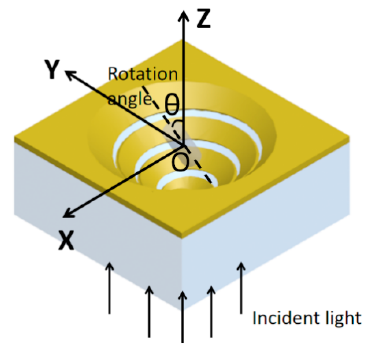
Therefore, we also studied the optical torque acting when a cylindrical micro-rod is lying at the center of the 3D PASL at a rotation angle
θ. As is shown in
Figure 7, the cylindrical micro-rod is in the
x-
z plane and rotated around the
y-axis. Here, the rotation angle
θ is defined as the angle between the main axis of the cylinder and the
z-axis, i.e., the angle between the dotted line and the
z-axis in
Figure 7. The parameters of the 3D-PASL in this case are
h0 = 625 nm and
gap = 800 nm. The cross-sectional radius of the cylinder is 200 nm, and its height is 1400 nm. The cylinder is assumed lying at the center of the focus (under left-hand circularly polarized excitation) or the plasmonic vortex (under right-hand circularly polarized excitation). The optical torque
T that is exerted on the cylinder has also been calculated by integrating the Maxwell stress tensor
over a surface that encloses the object under study, as follows:
Here,
r is the moment arm in the angular momentum flux. The relationship between the optical torque and the rotation angle is shown in
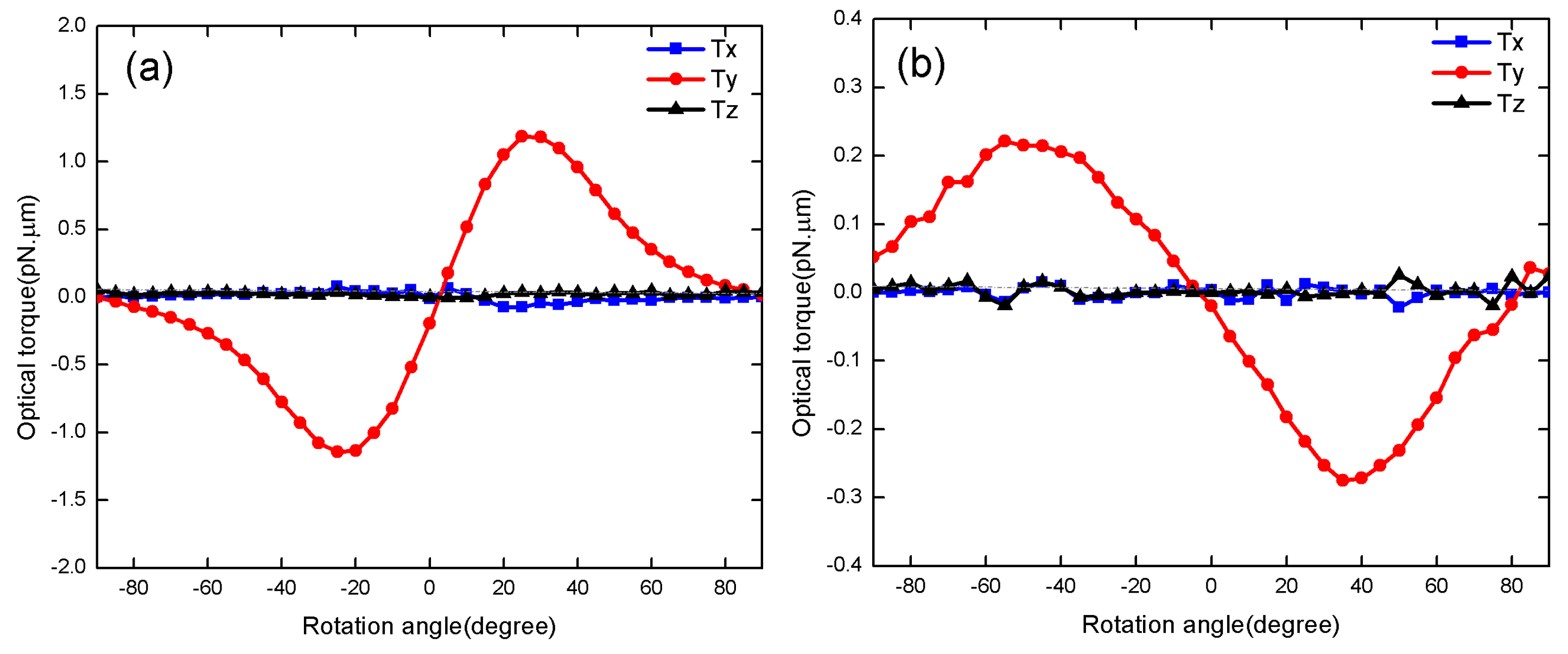
Figure 8a,b under left-hand circularly polarized excitation and right-hand circularly polarized excitation conditions, respectively.
Figure 8a shows that the torque in the
y-direction plays a major role when the cylinder rotates around the
y-axis. When the rotation angle ranges from 0 to 90°,
Ty is greater than 0, which means that the optical force tends to rotate the micro-rod towards the vertical direction (i.e.,
θ = 0). Additionally, when the rotation angle is between 0 and −90° (i.e., it is rotating in the opposite direction),
Ty is less than 0, which also indicates that the optical force tends to rotate the cylinder back towards the vertical direction. Therefore, when subjected to left-hand circularly polarized excitation, the optical force stabilizes the cylinder in the vertical direction at a rotation angle of 0° with respect to the optical axis. When the cylinder was placed in the plasmonic vortex (i.e., under right-hand circularly polarized excitation), with results as shown in
Figure 8b, we found that the optical torque in the
y-direction reached a maximum when the rotation angle was approximately ±45°, and the optical force then tends to rotate the rod towards the horizontal direction. However, the rotation angle at the maximum torque is different under the left-hand circularly polarized excitation conditions, this is because of the different beam waists of the focal point and the plasmonic vortex.


