1. Introduction
Understanding the interaction of elastic waves with surface defects like cracks, corrosion pits, topographic irregularities, etc., is critical for the potential development of ultrasonic nondestructive evaluation (NDE). However, the wave scattering problem remains a challenging area of research due to the complexity of the scattering phenomenon. For this reason, most of the works in the literature are performed with the use of numerical methods, such as the finite element (FE) method [
1], the boundary element (BE) method [
2], or the finite element boundary integral (FE-BI) approach [
3]. For a three-dimensional (3D) scattering problem, investigation with numerical methods is highly computationally expensive. Computational times remain of the order of several hours for one particular incident wavefield, even on powerful machines. Analytical or semi-analytical solutions to such problems are therefore desirable. They provide independent validation of numerical methods and enable rapid simulations of scattering from large populations of different scatterers. They also enable the relative contributions of different modes (e.g., propagating or non-propagating) to be examined to provide insight into the physics of the scattering process.
For the present paper, we studied the general three-dimensional problem of surface wave scattering by a cavity of arbitrary shape on the surface of a half-space. Two approximate methods using concentrated loading and distributed loading for the theoretical analysis of the scattered field are introduced. Examples of calculations include the scattering of surface waves by a spherical, a circular cylindrical (coin-shaped), and a square cylindrical cavity. Experimental work was carried out to verify the analytical solutions and it is followed by a discussion on the results of comparison. The investigation is the very first theoretical approach for obtaining the solutions of the scattering of surface waves by a three-dimensional cavity of arbitrary shape. Closed-form expressions that represent the scattered wave field due to the interaction with the cavity are derived. For these explicit solutions, computation of the scattered amplitudes is extremely simple. The approximation models can offer a much lower computational cost and time with a reasonable accuracy in comparison with the existing numerical methods. They are also able to provide insight into the physics of the scattering process that is important to solving inverse scattering problems.
With respect to earlier work, much of the work in the literature has been concerned with scattering by two-dimensional surface-breaking cracks. Typical examples of analytical work are References [
4,
5,
6]. Semi-analytical solutions were obtained, for example, in References [
7,
8]. Numerical work was carried out using the finite element method [
1] and the boundary element method (see References [
9,
10]). The scattering of surface waves by a two-dimensional cavity was theoretically investigated in our earlier works [
11,
12,
13]. Defect detection in rails using surface waves was also studied by Hesse and Cawley [
14]. In a related category are papers on scattering by strips and grooves [
15,
16,
17,
18,
19]. A review of the scattering of elastic waves by defects was presented in Martin [
20] (pp. 141–143). The related problem of the scattering of Lamb waves by a surface defect in a layer has received considerable attention (see, for example, References [
2,
21]).
In three dimensions, the scattering of elastic waves by canyons of arbitrary shape was studied using an indirect boundary integral equation method [
22]. The 3D scattering of guided waves by a through-thickness cavity with an irregular shape in an isotropic plate is investigated in Moreau et al. [
23] and scattering signal analysis of a cylindrical structure from a torsional wave is presented by Lee [
24]. An analytical solution for the scattering of ultrasonic guided waves by flat-bottomed cavities with arbitrary shape in a plate was introduced in Moreau et al. [
25]. Grahn [
26] discussed the scattering of Lamb waves from a circular partly through-thickness hole.
This paper proceeds through seven sections.
Section 2 states the problem as the superposition of the incident wave and the scattered field. It is shown that the scattered field is equivalent to the field radiated by surface tractions on the surface of the cavity. These surface tractions were obtained from the incident wave. Free Rayleigh surface waves propagating in a half-space are presented in
Section 3. A summary of the reciprocity approach to surface wave motion used in this paper is discussed in
Section 4. The analytical approach that uses distributed loading for a scattering of surface waves by a three-dimensional cavity is introduced in
Section 5.
Section 6 is devoted to the derivation of the scattered field by a spherical, a cylindrical (coin-shaped) and a square-shaped cavity. Experimental work is conducted, and the experimental measurements are compared with the analytical findings in
Section 7. Major conclusions drawn from this investigation are given in
Section 8.
2. Statement of the Problem
Consider a homogeneous, isotropic, linearly elastic half-space
in the Cartesian coordinate system
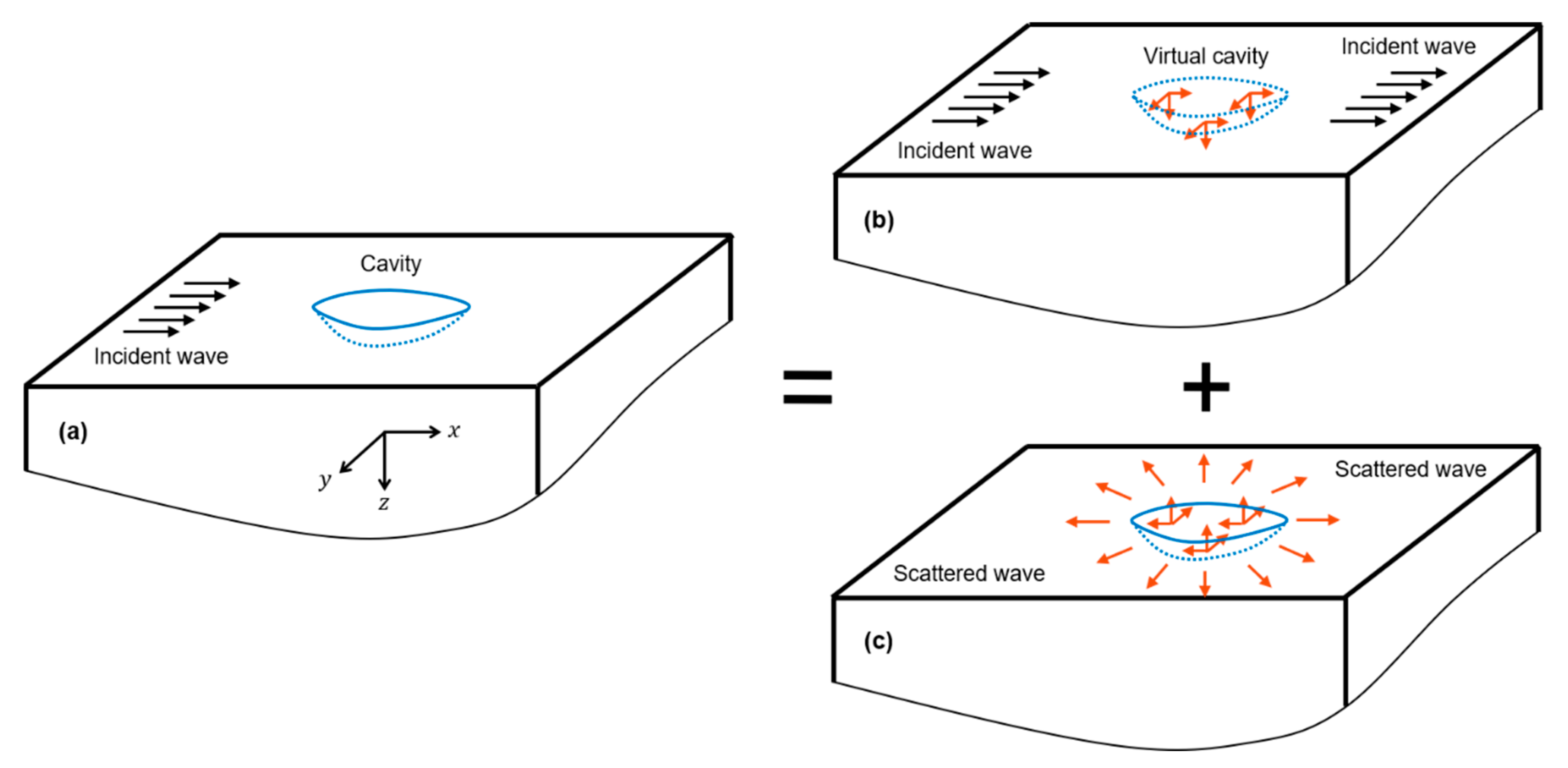
. The half-space contains a cavity on the surface as shown in
Figure 1a. A two-dimensional plane surface wave propagating in the
-direction is incident on the cavity. The interaction of the surface wave with the cavity generates a scattered wavefield
(
Figure 1c), which is of interest and will be studied theoretically in this paper. Using the decomposition principle, which is demonstrated in
Figure 1, the total wavefield
(
Figure 1a) is equal to the summation of the incident wavefield
(
Figure 1b) and the scattered field
. It should be noted that the incident field considered here is a two-dimensional (2D) surface wave, while the scattered field is a 3D surface wave. The far-field displacements of 3D surface waves radiated from a cavity were determined analytically and experimentally and are presented in the next sections.
With the linear decomposition given in
Figure 1, the scattered field is equivalent to the field generated by the application of a distribution of the tractions applied on the surface of the cavity. These traction components are equal in magnitude but opposite in sign to the corresponding tractions due to the incident wave on a virtual cavity in the half-space without the cavity. Therefore, they can be computed from the stress components of the incident Rayleigh wave and the outward normal vectors of the cavity. It should be noted that for the scattered problem given in
Figure 1c, the calculated tractions will generate both body waves and three-dimensional surface waves. It was discussed in the literature (see page 55 of Ewing and Zardetzky [
27] and page 321 of Achenbach [
28] for details) that for the three-dimensional case, the surface waves attenuate with a distance from the point of excitation according to
while the body waves decay according to
, where
is the distance from the point of application. Therefore, the surface waves dominate at a sufficiently large distance from the excitation point. The displacements of the scattered surface wave field are of interest and are determined in this article.
Two analytical approximation approaches will be presented. When the depth and the width of cavities are both much smaller than the incident wavelength, the tractions acting on the cavity surface can be replaced by three resultant loads applied at the origin of the coordinate system. This approximation is simple in the calculation but is supposed to be less accurate when the size of the cavity (depth and width) is comparable to the incident wavelength. As an improvement, a distributed approach is considered in which the application of the distributed tractions acting on the cavity surface is shifted to the surface of the half-space. The traction components are first computed for every point of the cavity surface. The reciprocity theorem is then applied to the equivalent loads that are applied on the surface of the half-space to obtain the displacement amplitudes of the scattered field. The total displacement amplitude of the scattered field is a superposition of the amplitudes generated by the loads at every point on the surface.
3. Free Surface Waves in a Half-Space
The possibility of a wave traveling along the free surface of an elastic half-space such that the displacements decay exponentially with distance from the surface was first considered by Rayleigh [
29]. Additional related studies can be found, e.g., in the pages 187–194 of the textbook by Achenbach [
28]. A surface wave, also called a Rayleigh wave, is defined by an angular frequency
and a wavenumber
where
is the surface wave velocity; other values include the Lame constants
and the mass density
. For a Cartesian coordinate system
, the displacements of the incident surface waves along the half-space
in the positive
-direction are of the forms:
where
is the complex amplitude;
indicates time; and
are dimensionless quantities. For an elastic half-space with the material properties given, the well-known equation for the phase velocity of surface waves (see page 32 of Achenbach [
28]) has a unique solution independent of the wavenumber. These dimensionless quantities, therefore, depend only on the material properties of the half-space. They are not presented here for the purpose of simplicity but curious readers can find their expressions in, for example, Phan et al. [
30]. Note that the stress components can be easily calculated from the displacements with the help of Hooke’s law.
4. Surface Wave Motion Generated by a Time-Harmonic Point Load
This is a three-dimensional problem. The surface wave motion generated by a time-harmonic point load can be calculated in a simple manner using the reciprocity theorem, with input being the actual surface wave with an unknown amplitude and a virtual free surface wave [
30,
31]. The method requires expressions for the displacements and the stresses of free surface waves, preferably in an analytical form, but numerically obtained forms can also be used. Suppose that the half-space is subjected to a time-harmonic point load at the surface pointing in an arbitrary direction. Without loss of generality, the coordinate system can be chosen such that the load acts in the
-plane at the origin of the system. The surface wave response is then sought as the superposition of the responses due to the normal component of magnitude
in the
-direction and the horizontal component of magnitude
in the
-direction.
For surface wave motions radiated from a point load, it is convenient to also use a cylindrical coordinate
defined by
and
along with the Cartesian coordinates
. Solutions of surface wave motion by the reciprocity approach are obtained in Phan et al. [
30]. Here, we summarize the results, which are later used for solving the three-dimensional scattering problem. The vertical displacement of surface waves generated by a vertical loading
in the
-direction may be written as:
For a horizontal load
in the
-direction, the generated displacement is of the form:
In Equations (2) and (3),
represents the
order Hankel function of the
kind and
is a dimensionless quantity determined using:
5. Scattering of Surface Waves by a Cavity of Arbitrary Shape
A plane surface wave propagating in the
-direction is incident on a three-dimensional cavity of arbitrary shape at the surface of an isotropic homogeneous elastic half-space. The incidence generates a scattered field that is of interest in this article. This section introduces two approximations to the theoretical analysis of the scattered field. Consider a cavity on the surface of a half-space as given in
Figure 2. In the coordinate system
, suppose that the surface of the cavity
is defined by
. Then the outward normal vector
of
can be found using:
where
and
.
From the linear decomposition principle, as stated in
Section 2, the scattered field is equivalent to the field generated by the application of the distribution of tractions on the surface of the cavity, as shown in
Figure 1c. These tractions are equal in magnitude but opposite in sign to the corresponding tractions due to the incident wave on a virtual cavity in the half-space without the cavity, as shown in
Figure 1b. Thus, they are equal to
where
are determined from the stress components of the incident Rayleigh wave and the outward normal vector as
. The tractions, in turn, generate the scattered field, which is of concern in this paper. It should be noted that these tractions generate body waves, as well as surface waves radiating from the cavity. In the three-dimensional scattering, the surface waves attenuate with the distance from the points of excitation on the cavity according to
while the body waves decay according to
, where
is the distance from the cavity. Therefore, the surface waves dominate at a sufficiently large distance from the cavity.
5.1. Concentrated Loading Approximation
As a simple approximation, the tractions on the surface of the cavity are replaced by three equivalent resultant forces applied at the origin of the coordinate system in the same directions. These forces then generate a scattered field of surface waves in the half-space. This approximation is supposed to be valid only when the depth and the width of the cavity are very small in comparison with the wavelength.
For an incident surface wave propagating in the positive
-direction with amplitude
, the resultant forces
are obtained via integration of the tractions over the surface
. These forces generate a field that approximates the scattered field. The total vertical displacement of the scattered field in the
-direction is the summation of the displacements generated by the resultant forces
and is written as:
5.2. Distributed Loading Approximation
An approximation using distributed loading is now considered. The tractions first calculated at every point on the surface of the cavity are shifted to the surface of the half-space. The reciprocity theorem is then applied for these equivalent surface loads to obtain the displacement amplitudes of the scattered field. In the concentrated loading approximation, the loads that generate the scattered field are all applied at the origin of the coordinate system. For the current approximation, the loads are applied over an area, which is the projection of the cavity on the surface of the half-space. This method is believed to be valid for shallow cavities. The obtained theoretical predictions were compared with the experimental results in order to understand the limitations of the proposed approach.
Suppose that a point source is applied at
, or
using cylindrical coordinates, and the observation point is located at
, as illustrated in
Figure 3. Here, the observation point is chosen with
for the purpose of simplicity. Note that solutions for other points, i.e.,
can be easily gained by using Equations (2) and (3). The following relations are found in
Figure 3 for the case of
:
For an incident surface wave propagating in the positive
-direction with amplitude
, the point forces corresponding to the tractions on the surface of the virtual cavity at
can be calculated using:
It is convenient to also represent the expressions of
and
given by Equation (8) in the cylindrical coordinate
. For a time-harmonic load at the origin of the coordinate system, the vertical displacements follow from Equations (2) and (3). In the case of a time-harmonic load applied at
as in
Figure 3, the total vertical displacement of the scattered field at the observation point
is the summation of the surface wave fields generated by
. Thus:
It should be noted that the displacement given in Equation (9) is dependent on frequency since its expression appears with a frequency term via the wavenumber .
7. Experimental Confirmation and Discussion
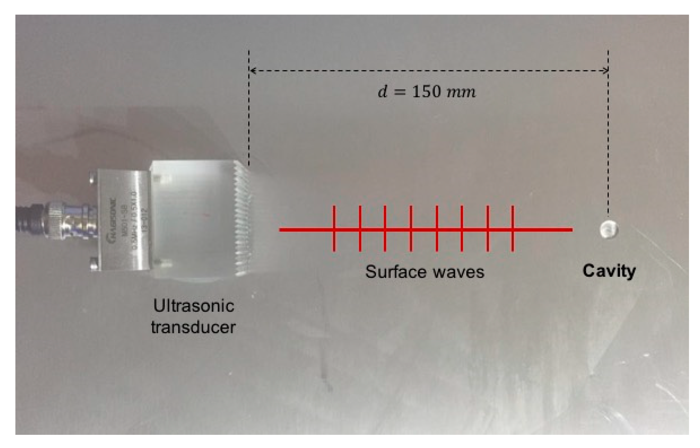
An experimental study was carried out in order to provide practical validation of the findings of the analytical work in the previous sections. The experimental setup using an ultrasonic pulse-echo technique is illustrated in
Figure 5. The piezoelectric (PZT) transducer (Hagisonic, Daejeon, Republic of Korea) placed on the critical angle was first used to transmit a surface-wave pulse with a central frequency of
toward the cavity. It was then used as a receiver to record the echoes of the scattered surface waves. The distance from the transmitter to the defect was chosen as
, which was about twenty-five wavelengths. At this distance, the surface waves completely dominated the scattered wave field since the body waves had almost vanished.
A thickness steel plate, which had a shear modulus of , a Lame’s constant of , and a density of , was used for the experimental program. The thickness, which was more than four wavelengths, guaranteed that no ultrasonic signal was reflected from the bottom of the plate. The spherical, circular cylindrical, and square cylindrical cavities were made on the surface of the steel material for the experiments. Each of three shapes included ten cavities of same width and different depth. This meant that for each shape the width of cavity was fixed while its depth varied such that dimensionless quantity , where is the wavenumber, varied.
By recording the echoes from the defects, the displacement amplitudes of the scattered wave fields were determined. These results were then divided by the referenced amplitude of the incident surface wave, which was measured using the pitch catch technique, to obtain the normalized amplitude ratios. For each cavity configuration, this experimental process was repeated five times to calculate the means and the standard deviations of the normalized ratios. These experimental results were assumed to represent the scattered surface wave fields.
For the analytical study, the normalized amplitude ratio was also defined by the proportion of the displacement amplitude of the scattered field to the one of the incident field. In the following, the comparisons between the analytical results and experimental data for the absolute values of the normalized amplitude ratios are shown versus the dimensionless for the cases of a spherical, a circular cylindrical, and a square cylindrical cavity.
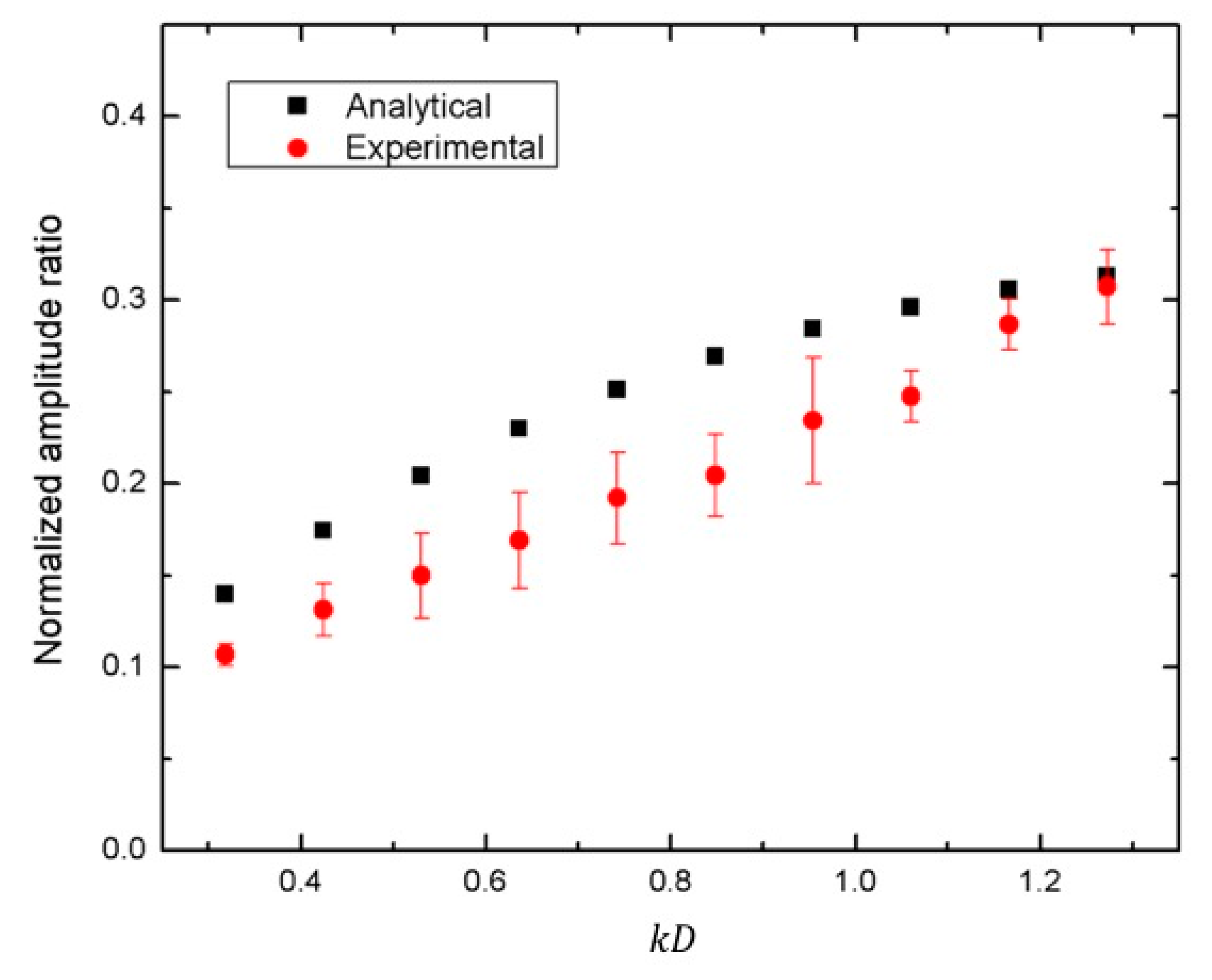
The first example was the study for ten spherical cavities with
varying from
to
, while
. The comparison results are exhibited in
Figure 6. The theoretical and experimental amplitude ratios were observed to increase with the increase of the cavity depth. An excellent agreement was found between the two curves. They had only about a 6–8% difference on average. The comparisons between the analytical predictions and the experimental measurements of the normalized amplitude ratios for the case of a circular cylindrical cavity and a square cylindrical cavity are shown in
Figure 7 and
Figure 8, respectively. In these studies,
varied between
and
, while
. A very good agreement of the trend was obtained in both sets of results. In terms of magnitude, the experimental points and the predicted points were in reasonable agreement. There were, however, some differences in the details between the two sets of calculations. It is believed that the differences were due to the analytical approximation rather than the experiment. For the case of a spherical cavity, which had a smooth surface, an excellent agreement is shown in
Figure 6. As the surfaces of the circular and square cylindrical cavities were not smooth, the comparisons between the analytical and experimental results show some differences in
Figure 7 and
Figure 8. It should also be realized that the analytical calculations and the experimental results increased the differences with an increase of the size (the volume) of the cavities from the spherical cavity (
Figure 6) to the cylindrical cavity (
Figure 7) and to the square cavity (
Figure 8). This proposed approach, therefore, has limitations regarding the degree of smoothness and the size of the cavity.

 ,
, 


