1. Introduction
The regulation of pollutant emissions in internal combustion engines has continuously become more stringent in recent years. This fact drove the engine development process, aimed at reducing the fuel consumption and the environmental impact. One of the results of this trend is the use of exhaust gas aftertreatment systems (ATS) [
1]. In the case of the particulate matter, wall-flow particulate filters (PF) are nowadays a standard technology necessary to fulfil current regulations because of their high filtration efficiency, both for diesel (diesel particulate filter—DPF) [
2] and gasoline (GPF) [
3] engines. In this regard, PFs allow an effective reduction of the particle emission both in terms of mass and particle number, with filtration efficiency typically over 90% dependent on several parameters such as the DPF gas flow [
4], the particle size, the soot mass load or the fuel [
5].
The use of the particulate filter has a great impact on the engine performance and its fluid-dynamic behaviour, increasing the exhaust backpressure [
6] and affecting the wave dynamics of the exhaust line [
7]. The accumulation of soot inside and on the porous walls of the filter [
8] aggravates these effects and leads the engine specific fuel consumption to increase [
9]. For this reason, and taking into account the limited capacity of the filter for soot accumulation [
10], after a certain operating time it is necessary to induce a regeneration process consisting of the oxidation of the soot particulates stored inside the filter [
11]. Two different strategies are used for this purpose. Active regenerations, which are promoted periodically, make use of an external energy source [
12] to trigger the soot oxidation process. Instead, passive regeneration strategies produce such oxidation without an external energy source. These passive solutions help to reduce the frequency of active events in diesel engines [
13] and are even sufficient in gasoline engines [
14].
In the particular case of active regenerations, different techniques can be used to increase the exhaust gas temperature until the level needed for the soot to oxidise [
15]. Among them, the most common one is the use of fuel post-injections, which consists of the injection of an amount of fuel in a single or separate portions after the main injection [
16] during the late expansion stroke [
17]. The extra fuel injection gives as a result a significant increase of the concentration of unburned hydrocarbons (HC) in the exhaust gases. Once these hydrocarbons arrive to the diesel oxidation catalyst (DOC), their oxidation produces a significant increase in the temperature at the DPF inlet [
18]. However, these strategies imply an increase of the fuel consumption as a function of the impact on the specific fuel consumption and on the regeneration duration. Thus, it is necessary to optimise them to reduce as much as possible this penalty [
19].
The main parameters to define the post-injection pattern in terms of the impact on the fuel consumption are the delay of the injection command with respect to the main injection timing [
20] and the fuel mass rate during this event [
16]. Both parameters play a significant role in the properties of the exhaust gas arriving to the catalyst, mainly in terms of its temperature and the HC concentration [
21]. In order to maximise the regeneration efficiency it is typical to combine the post-injection strategies with other engine control actuations, such as to act on the exhaust gas recirculation (EGR) valve, aimed at increasing the exhaust temperature [
22] or the closure of the intake throttle valve, limiting the air flow coming into the cylinders in order to achieve richer equivalence ratio mixtures and higher HC concentration during the main combustion event [
23]. Parks et al. [
24] studied the relationship between the exhaust gas temperature and the optimal post-injection timing for the regeneration. They concluded that for low temperature it was necessary to cause an increase of the temperature inside the cylinder during the combustion so that the post-injection had to be performed relatively close to the main injection event to ensure its ignition. Instead, when the exhaust temperature was higher it was more efficient to induce the oxidation in the catalyst so that the post-injection event should be delayed.
Another important aspect to define the regeneration strategy is related to the properties of the fuel, which determine the specific composition of the HC [
25] and, consequently, the DOC response [
26]. Chen et al. [
27] concluded that the regeneration was slower when using biodiesel fuel due to the lower temperature reached in the DOC compared to a regular diesel fuel. In this sense, the research done by Jeftić et al. [
25] analysed the HC, CO and soot emissions produced by the post-injection of n-butanol and diesel fuel, highlighting the change in the composition of HC due to the different fuels and the lower soot emissions characteristic of the operation with n-butanol.
Defining the optimum regeneration strategy as the one leading to the minimum fuel consumption, i.e., the optimum combined impact of post-injection rate and regeneration duration, the current work analyses the efficiency of the timing and fuel mass rate of late fuel post-injection events in terms of exhaust gas temperature increase, change in specific fuel consumption and dynamics of the active regeneration. Other important aspects for the definition of the regeneration strategy, such as the fuel dilution inside the engine oil [
28] or the thermal fatigue in the particulate filter [
29], are out of the scope of this work.
In order to perform this study, a set of computational models are used to analyse in detail the linked engine and ATS response. An engine model implemented in GT-POWER [
30] is used to predict the influence of the post-injection event on the specific fuel consumption and the gas properties at the DOC inlet. These boundary conditions are next applied as input for dedicated lumped DOC and DPF models, which were previously validated within a wide range of engine experimental data. Firstly, the dependence of the DPF inlet temperature on the post-injection settings is analysed, defining the efficiency of each strategy from the exhaust gas temperature increase. The influence on the dynamics of the regeneration of the temperature increase and the available
concentration at the DPF inlet is finally studied. This is done to make the focus centre on the changes in the pre-heating, maximum reactivity and late soot oxidation stages as a function of the post-injection parameters. This way, the impact on the duration and the required fuel consumption of each stage is evaluated, making evident the variation in sensitivity to the post-injection timing and fuel mass rate of different engine operating conditions.
2. Modelling Tools
Figure 1 shows schematically the engine used in this work as an exhaust gas generator. This way, different representative boundary conditions of the exhaust gas flow useful for the analysis of DPF active regeneration strategies are defined concerning dwell time, exhaust temperature and
concentration. The main characteristics of the engine and the ATS, which was composed by a close-coupled DOC and DPF brick, are summarised in
Table 1 and
Table 2 respectively. In particular, a 1D gas dynamics model was built in GT-POWER software. To do that the engine was tested coupled to an asynchronous dynamometer for engine speed and torque control. The main characteristics of the instrumentation used to measure the air and fuel mass flow as well as the flow properties in the intake and exhaust lines are summarised in
Table 3. The gas composition at the DOC inlet and outlet was measured by a Horiba Mexa 7100 gas analyser and AVL 439 opacimeter. A detailed calibration of the engine model is provided in [
31].
The predictive capabilities of the engine model were improved by specific sub-models. This way, the DI-Pulse (direct-injection diesel multi-pulse mode) model available in GT-POWER was used to simulate combustion process and the raw pollutant emissions from the injection rate profile [
30]. The fuel mass is tracked as it is injected, evaporates, mixes with surrounding gas and finally burns. To do that, each injection event is treated as an injection pulse that is tracked separately from all the pulses, without a distinction between pilot, main or post-injection being that the injected fuel is added to the spray unburned zone. Therefore, the timing and the fuel mass rate define the late fuel post-injection to predict the effect that the modification of the injection profile has on the combustion and the pollutants formation. Concerning the last, the CO concentration was calculated based on the thermodynamic equilibrium whilst the raw HC concentration was determined as the difference between the injected and burned fuel mass. The amount of soot was calculated applying the Hiroyasu model [
30].
On the other hand, the turbocharger and ATS sub-models available in GT-POWER were replaced by dedicated user-functions available in OpenWAM [
32], which is an open-source gas dynamics software developed by CMT-Motores Térmicos [
33]. The turbocharger sub-model was applied aimed at a more precise simulation of the heat transfer [
34] and the mechanical losses [
35] in the turbocharger thus contributing to improving the prediction of the temperature at the turbine outlet [
31].
Once flow properties were defined at the ATS inlet, specific DOC and DPF models were applied to assess the impact of the active regeneration strategy on the soot oxidation. For the sake of completeness, these models are next briefly described.
2.1. DOC Model
A lumped modular DOC model is applied to compute the main physical and chemical processes affecting the flow properties at the DPF inlet [
26]. The model is based on the solution of the pressure drop, heat transfer and the chemical reactivity processes [
36]. Since this work is focused on the analysis of the DPF response during the regeneration, the heat transfer and chemical processes are modelled directly imposing the turbine outlet flow properties, i.e., mass flow, composition, pressure and temperature, as boundary conditions.
The pressure drop across the DOC is modelled based on a phenomenological approach assuming incompressible flow as [
36]
where
is the DOC inlet density,
is the DOC inlet velocity and
is the pressure drop coefficient of the device. This coefficient is specific to the system geometry and obtained experimentally as a function of the Reynolds number. The heat transfer phenomena are simulated applying a lumped nodal scheme adapted from a 1D modelling approach [
37]. The model accounts for the gas to wall heat exchange and the heat losses towards the environment. In addition, since the active regeneration is a transient process, the thermal inertia of the monolith substrate and the external canning is also considered to provide the temperature evolution at the DPF inlet. The nodal schemes corresponding to the monolith and the DOC canning are represented in
Figure 2 [
26].
The model definition is based on the discretization of the general heat transfer equation by centred explicit finite differences. If axial and radial heat transfer is assumed, the wall temperature at time-step
and node
is determined considering the gas temperature and the substrate-canning state at the previous time-step
p. Taking into account the definition of every control volume, i.e., thermal properties and heat transfer area, the substrate and canning temperatures are finally computed as:
According to Equations (
2)–(
4), the substrate temperature (
), the internal surface temperature (
) and the external surface temperature (
) are governed by the thermal capacity (
C) and the equivalent thermal resistance between two neighbouring nodes (
R), whether gas, substrate or canning. The term
is related to the heat power of the chemical reactions taking place in the washcoat.
The DOC chemical mechanism considers the CO and HC oxidation as well as the physisorption of HC on the zeolites present in the washcoat and the NOx redox reactions:
The conversion efficiencies of
and
are calculated by the integration in the axial direction of the 1D transport equations of these species in the gas bulk and over the catalytic surface. Assuming quasi-steady flow, these are written as
where Equation (
9) is the bulk gas chemical species conservation equation and Equation (
10) represents the chemical species transport in the washcoat of the pollutant species
n. The bulk gas transport equation takes into account the convective transport of the species along the monolith channels and the bulk mass transfer towards the washcoat interface. As described by Equation (
10), the gaseous species are then transported by diffusion from the interface to the washcoat internal volume, where the reaction takes place in the active sites.
The reaction rate (
) for every pollutant species
n accounts for all reactions
j in which it is involved. It is calculated from the Arrhenius kinetic constant assuming first-order kinetics and including limitations due to inhibition and internal pore diffusion [
26]. Due to the minor effect of
in the soot oxidation during active regeneration processes and the high temperature in the DOC during this process [
38], the
ratio at the DOC outlet was determined assuming thermodynamic equilibrium [
39]. Therefore, the reaction rate for the CO and HC oxidation reactions is written as
whilst the HC adsorption and desorption reaction rates are given by:
2.2. DPF Model
The gas properties at the DOC outlet define the boundary conditions for the modelling of the DPF. Like in the DOC case, a modular lumped model is employed in the DPF, including sub-models for pressure drop and heat transfer besides specific routines to account for filtration, regeneration and porous medium properties.
The amount of soot cumulated in the DPF determines the dynamics of the filtration [
40] and regeneration [
38], as well as the pressure drop [
41]. The variation in the soot mass inside the DPF is modelled as a function of the filtrated and oxidised soot amounts per unit of time according to Equation (
14),
where
is the variation of DPF soot mass per time-step,
is the filtrated soot mass rate,
is the oxidised soot mass rate and
is the time-step duration.
The amount of soot oxidised per unit of time as well as the heat released during the regeneration are determined from the depletion rate of the gaseous reactants depletion rate (
and
), as shown in Equation (
15),
where
is the Carbon molecular weight,
is the stoichiometric coefficient of the gaseous reactant and
is the depletion rate of each reactant expressed in mole terms. The depletion rate is obtained solving the reactants species transport along the porous medium, i.e., particulate layer and loaded porous wall region, according to Equation (
16)
which considers the diffusion of the reactants into the soot particles and their adsorption according to a Langmuir isotherm, as discussed in [
38]. In particular, the terms
and
represent the specific external and internal surfaces of the soot particle, respectively, being
the internal pore diffusion efficiency. Additionally,
and
are the adsorption constant and the partial pressure of reactant
n.
2.3. ATS Models Calibration
Table 4 summarises the chemical parameters in the DOC model, both for Arrhenius kinetic terms (Equation (
17)) and inhibition terms (Equation (
18)) [
42].
This set of parameters was obtained from specific tests in steady-state and transient conditions.
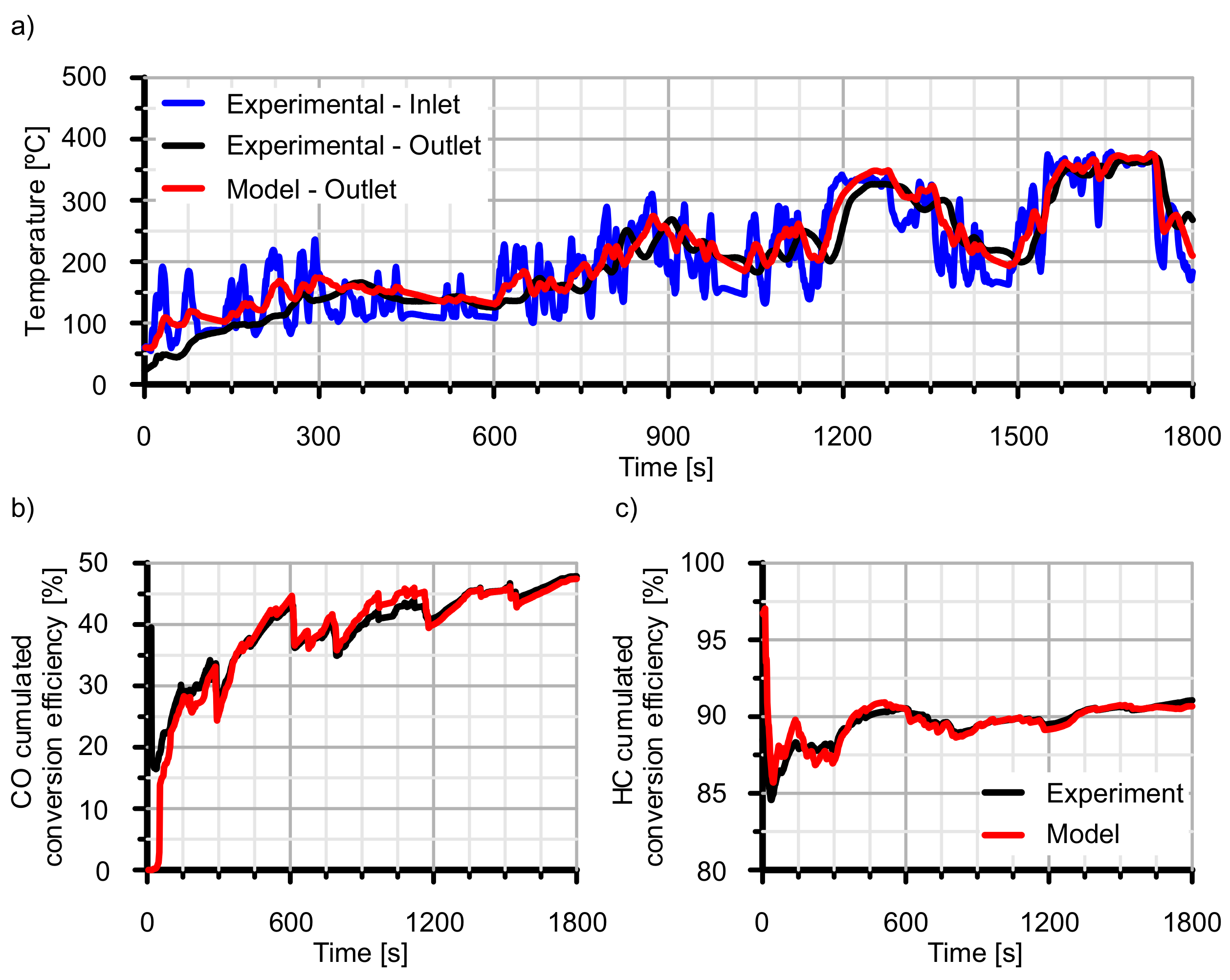
Figure 3 shows the comparison between experimental and modelling results for DOC outlet gas temperature and pollutants conversion efficiencies. The tests covered three engine speeds (1500 rpm, 2000 rpm and 2500 rpm) and an engine load variation from 5% to 40%. The combination of these engine speeds and loads contributed to vary the mass flow and the gas temperature at the DOC so that the low to high conversion efficiency range was tested accounting for chemical kinetics, i.e., temperature controlled and dwell time, i.e., mass flow controlled, effects. The tests were performed in different series corresponding to each engine speed with increasing load. Each operating condition was maintained for 300 s to ensure thermal stabilisation before the measurement and transitioning to the following load step.
Thus,
Figure 3a shows the modelled DOC outlet gas temperature compared to the experimental data. The high accuracy to predict this temperature, with an absolute error ranging ±5
C, is critical since it is one of the most important parameters to evaluate the effects of the fuel late post-injection on the DPF regeneration. In turn, this good agreement results from an accurate prediction of the pollutants conversion efficiency, which is shown in plots (b) and (c) of
Figure 3 for CO and HC respectively together with the absolute error. It is possible to observe that the CO conversion efficiency is below 90% for the points with a lower inlet temperature due to chemical kinetic limitations. The only exception to this behaviour corresponds to the point at 1500 rpm and 5% in engine load, where the conversion efficiency is higher thanks to the longer residence time. For the rest of the operating points, characterised by higher exhaust temperature (over 200
C), the conversion efficiency is higher than 95%. Similarly, the operating points with the lowest inlet temperature have HC conversion efficiency below 90%. In these points, the obtained conversion efficiency is due to two different phenomena. On the one hand, the temperature is not enough to ensure a complete oxidation of the HC in the exhaust gas. On the other hand, this low temperature promotes the HC adsorption on the zeolite washcoat. Moreover, it has to be considered that the zeolite is partially saturated due to the HC cumulated during the thermal stabilisation. Again, once the temperature reaches 200
C the conversion efficiency increases over 90%. The variations of the efficiency observed in this area are due to differences in temperature and pollutants concentration, affecting the catalyst inhibition processes. However, the model well captures the experimental trends observed.
The performance of the DOC model was also evaluated against highly transient operation during a complete Worldwide harmonized Light duty Test Cycle (WLTC). Again, the comparison between experimental and modelled DOC outlet gas temperature and pollutants conversion efficiency in
Figure 4 confirms the good ability of the model to reproduce the DOC response. The trend in outlet gas temperature is very well captured so that the thermal inertia of the DOC monolith is properly represented. Only a shift between the experimental and modelled temperature is observed along the cycle. It is supposed to be related to the thermal inertia of the thermocouples, as discussed by Guardiola et al. [
43]. In particular, the DOC inlet temperature is very dynamic. It indicates that this measurement might be affected (delayed) by the thermocouple thermal inertia. As a consequence, the modelled outlet gas temperature is also delayed with respect to the actual one. In the outlet section, although the measured DOC outlet temperature is also influenced by the dynamics of the thermocouple response, the measurement is closer to the actual temperature. This is because of the fact that the thermal inertia of the DOC governs the temperature profile, which tends to be quasi-steady.
Figure 4 shows the evolution of the cumulated conversion efficiency of CO and HC in plots (b) and (c) respectively. Since the cumulated conversion efficiency is considered, a small deviation in the instantaneous prediction would have a great influence at the early stages. This is observed in the CO cumulated conversion efficiency. The model predicts 0% in CO cumulated conversion efficiency until second 40. At this time, it starts to increase, i.e., the substrate temperature is high enough to promote the CO oxidation and the instantaneous conversion efficiency is progressively increasing. When the model predicts the initiation of CO oxidation, the experimental results also present a minimum and both signals tend to converge. However, the experimental CO cumulated conversion efficiency is sharply decreasing during the early WLTC. Being that the temperature is very low, it is attributed to an initial instantaneous measurement error that is progressively corrected by the cumulated result. Therefore, despite these minor differences in CO, a good correlation between the model and the experiment can be assumed from the start of the cycle. The model performance evidences the precise modelling of the substrate temperature and the chemical kinetics over the WTLC concerning both oxidation and also adsorption-desorption in the particular case of HC.
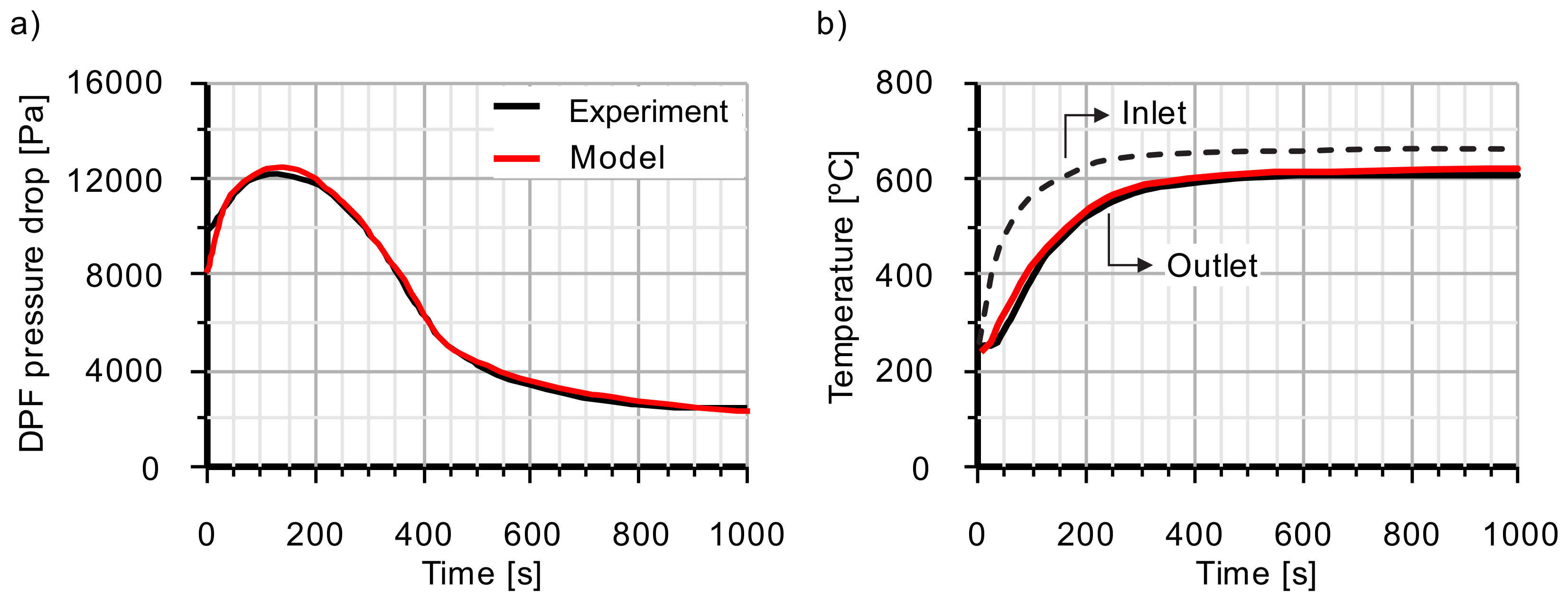
Concerning the DPF model, active and passive regeneration tests were performed to calibrate the soot oxidation kinetic constants, which are defined in
Table 5. The active regeneration event is represented in
Figure 5. The engine was run at 1500 rpm and 50 Nm until the soot loading reached 5.5 g/L. Next, the active regeneration was triggered on a steady-state condition of 2000 rpm and 90 Nm applying a 6 mg/cc post-injection at 60 CAD aTDC (Crank Angle Degrees after Top Dead Center).
The mass flow across the filter, the inlet gas temperature and the outlet pressure were imposed as a boundary condition to calibrate the model. Therefore, the objective was to predict the evolution of the pressure drop across the DPF and the outlet gas temperature. Being the mass flow constant, the temporal evolution of the pressure drop is a consequence of the soot loading and the gas temperature, which both depend on the soot oxidation rate.
Figure 5a shows this comparison in terms of pressure drop, showing a very close match between experiments and simulations. Only a deviation is noticed at the very beginning of the test since the calibration gave more weight to the regeneration evolution than to the initial condition. Anyway, the model quickly converges to the experimental trace being capable to properly predict the pressure increase at the beginning of the regeneration due to the inlet gas temperature increase and the subsequent reduction as the soot mass load within the filter decreases. Similarly,
Figure 5b depicts the evolution of the temperature at the DPF outlet, well reproduced both during the thermal transient, finishing around second 300, as well as when the steady-state conditions are reached. In this case, a shift is again observed between the experimental and modelled DPF outlet temperature. As previously discussed, it is caused by the delay in the measured DPF inlet temperature. Despite that this measurement is more accurate than the one at the DOC inlet because of the DOC thermal inertia, it is still affected by the thermocouple characteristics. In turn, the DPF outlet temperature measurement is even more confident. Consequently, the shift in the outlet temperature provided by the models is more reduced at the DPF than in the DOC case, as also observed in
Figure 6a concerning the DPF response during the WLTC test.
The passive soot oxidation during the WLTC test was also modelled to get further sensitivity in the calibration of the regeneration model. Taking the DOC outlet conditions related to
Figure 4,
Figure 6 shows the DPF outlet gas temperature and the cumulated soot mass during the cycle. In this case, the DPF model certifies the good prediction of the thermal response even with low soot oxidation rate. According to
Figure 6b, the experimental filtrated soot mass is well captured by the model. In addition, the model provides the instantaneous soot mass load as a balance of filtrated and passively oxidised mass. Thus, the predicted soot mass at the end of the WLTC is 2.25 g, which is very close to the experimental value obtained by DPF weighing [
44].
3. Engine and DOC Response
Firstly, the effects of the late fuel post-injection on the engine performance and the gas properties in the exhaust are analysed varying the post-injected fuel mass rate and its timing. These results were achieved by using the gas dynamics engine model. Later on, the modelled flow properties at the turbine outlet, i.e., mass flow, pressure, temperature and composition, were imposed as boundary conditions to describe the response of the DOC.
Two engine operating points, which are defined in
Table 6, are evaluated. A medium-high load operating point without EGR (#A) is compared with a low load operating point with high HP-EGR rate (#B). Both points share a similar raw
concentration but represent different boundaries for good pollutants abatement. To consider closed EGR in point #A is an extreme case that is to evidence how the resulting DPF inlet temperature increases its sensitivity to the post-injection timing. It is representative of high in-cylinder temperature leading to the need to properly manage the late fuel post-injection timing. At the same time, low EGR rate engine operating conditions improve the dynamics of the soot oxidation in the DPF because of the high
concentration and mass availability after the DOC. It contrasts with the case of the same raw
concentration (DOC inlet, point #B in
Table 6) but high HP-EGR rate. This is representative of an operating condition which limits the available
mass across the DPF while at the same time providing high dwell time. The
availability makes the definition of the active regeneration strategy more dependent on the post-injected fuel mass rate.
Figure 7 shows the effect of the post-injection timing and the post-injected fuel mass rate on the brake specific fuel consumption (BSFC) and the torque.
Figure 7 shows in plots (a) and (b) how the increase of the fuel mass in the post-injection leads to an increase of the BSFC for both operating points and over the complete range of the study. As described by Jeftić et al. [
25] for high load and no-EGR conditions, point #A shows higher sensitivity to the post-injection timing on BSFC. This happens because of the increase of the engine torque, which is especially relevant when the post-injection delay with respect to the main injection is small [
27], as observed in
Figure 7c and to a lesser extent in
Figure 7d, in which the iso-torque lines evidence a lower slope. Thus, the torque increase becomes negligible as the post-injection is delayed, giving rise to a more evident penalty in BSFC, which gains dependence on the post-injected fuel mass rate for all points.
The impact of the late fuel post-injection on the raw HC and soot emissions is shown in
Figure 8. Plot (a) in
Figure 8 points out that point #A is characterised by increasing raw HC concentration as the post-injection is delayed and as the post-injected fuel mass rate increases at high delays. This behaviour agrees with the high torque increase as the post-injected fuel mass rate is done at reduced delays and the loss of dependence with mass as the post-injection is further delayed. The lower sensitivity of torque in point #B to the post-injected fuel mass rate, which is represented in
Figure 8b, makes the raw HC concentration gain further dependence to this variable besides the post-injection timing. Regardless, the raw HC emission increases with the delay in the post-injection as the engine load decreases and EGR is used.
Concerning soot emission,
Figure 8c shows that point #A is greatly dependent on the post-injection delay, increasing as the post-injection is advanced due to the incomplete combustion of the fuel in these conditions [
45]. Additionally, the increase of the temperature inside the cylinder induced by the partial combustion of post-injected fuel mass is not high enough to produce a relevant oxidation of the generated soot particles [
46]. The trend in raw soot emissions completely changes in point #B, as represented in
Figure 8d. A lower increase of the soot emissions compared to point #A is observed. This response is explained by the fact that the soot formation at low engine load is governed by the temperature of the gas inside the cylinder at the same time that the post-injection is performed. Being that this temperature is low, the reactions responsible of creating soot precursors are inhibited, thus avoiding the production of additional soot from the post-injection [
45].
The boundary conditions at the DOC inlet are completed with the gas temperature, which is shown in
Figure 9a and b for points #A and #B respectively. Comparing against
Figure 7c,d, the DOC inlet temperature profile is observed to be almost identical to that in torque. Settings increasing the amount of post-injected fuel burned into the cylinder lead to an increase in torque and DOC inlet temperature. Therefore, the exhaust gas temperature increases as the post-injection is closer to the TDC and, to a lesser extent, the fuel mass increases, as also discussed experimentally by Yoon et al. [
28].
By contrast, the pattern in the DOC outlet temperature is governed by the HC oxidation due to its high concentration, as plotted in
Figure 9c,d. It is possible to observe how higher post-injected fuel mass rate produces the highest temperature increase across the DOC. The delay in the post-injection also favours the increase of the DOC outlet temperature. However, this effect is much more relevant in point #A than in point #B since it is intimately related to the amount of post-injected fuel mass burned into the cylinder. In fact, it can be noticed how in point #A the region with the highest DOC outlet temperature corresponds to the lowest inlet one. The same conclusions are obtained from the analysis of point #B. Nevertheless, the dependence of the DOC outlet temperature on the post-injection timing is lower due to the lower torque variation as a function of this parameter.
This response evidences that the increase in the DOC inlet temperature is caused by the oxidation of the post-injected fuel into the cylinders. This contributes to increase the torque and leads to a final lower temperature at the DOC outlet for the same post-injected fuel mass rate. In fact,
Figure 9e,f indicate that the
concentration is only dependent on the post-injected fuel mass rate. In fact, it demonstrates that all the post-injected fuel is oxidised in the cylinder
the DOC.
Taking into account the effects of the different post-injection settings on the temperature field, it is possible to quantify how efficiently the invested energy is converted into an increase of the temperature at the DOC outlet. Firstly, the maximum temperature at the DOC outlet can be calculated for each operating point as the one that should be reached if all the heat released by the oxidation of the post-injected fuel was used to increase the exhaust gas temperature at the DOC outlet:
The maximum temperature is represented by the continuous series in plots (a) and (b) of
Figure 10 for each operating point and post-injected fuel mass rate. It is compared against the predicted temperature at the DOC outlet. The difference between theoretical and modelled values gets higher in both points as the post-injected fuel mass rate increases. Additionally, the predicted DOC outlet temperature is increasing as the post-injection is delayed. Therefore, the efficiency of the post-injection even increases as the post-injection is delayed. It is calculated according Equation (
20) and represented in
Figure 10c and d for points #A and #B respectively. In addition, these plots also make it evident that the lower the post-injected fuel mass rate is, the higher the post-injection efficiency is.
The trends in post-injection efficiency as a function of the timing and the fuel mass rate are mainly governed, as previously described, by the partial combustion of this fuel into the cylinders. If such an oxidation takes places, part of the energy available in the post-injection fuel mass contributes to useful work, thus increasing the torque; other second order effects on the post-injection efficiency are related to the VGT (variable-geometry turbocharger), which opens as the exhaust gas temperature increases and to the heat transfer until the DOC outlet. It is interesting to note that the lowest efficiency is obtained in point #A, characterised by high load without EGR, when the post-injection delay is minimum. However, the efficiency sharply increases with a slight delay (from 30 to 40 CAD aTDC) and a monotonous increase is kept till 60 CAD aTDC. With this timing, both operating points show the same post-injection efficiency, i.e., the dependence of this parameter on the operating point disappears.
4. Active Regeneration Analysis
Knowing the efficiency of the late fuel post-injection and the flow properties at the DPF inlet, the active regeneration process is next discussed. The gas composition, mass flow, pressure and temperature at the DOC outlet as a function of time, i.e., including the effect of the thermal transient due to the post-injected fuel heat release, were imposed as boundary conditions for the simulation of the DPF response. It was assumed that the initial DPF soot load of the filter was
, which is a usual upper limit for the start of the regeneration [
29].
The dynamics of the active regeneration is described based on the definition of the pre-heating, maximum reactivity and late oxidation stages [
38]. Every stage is defined as a function of the derivative of the pressure drop across the DPF and the soot depletion rate.
Figure 11a shows the evolution of the soot loading corresponding to the active regeneration used for the model calibration (
Figure 5) in
Section 2. The three regeneration stages are identified in
Figure 11b.
The active regeneration event starts with an increase of the pressure drop across the DPF, i.e., positive pressure drop derivative, corresponding to the pre-heating stage. This increase is related to the increase in exhaust gas temperature. The deviation between the experimental and modelled pressure drop shown in
Figure 5a at the beginning of the process causes the difference in pressure drop derivative observed in
Figure 11b. Nevertheless, as the substrate increases its temperature the soot oxidation initiates, which causes a progressive decrease of the pressure drop rate as observed in the experimental and modelled results. Consequently, a sudden increase of the soot depletion rate derivative takes place. Once the pressure derivative becomes equal to zero, the maximum reactivity stage is started. This second stage lasts until the minimum in pressure drop derivative. Its duration coincides with the maximum to zero derivative in soot depletion rate. Finally, the regeneration is slowly completed during the late oxidation stage, which is characterised by a gradual smooth increase towards zero of the pressure drop and soot depletion rate derivatives.
Considering the parametric study for the late fuel post-injection parameters,
Figure 12 depicts the duration of each active regeneration stage to achieve a consumption of 95% of the initial soot mass load. Both operating points confirm that a high delay in the post-injection is more convenient from the point of view of the velocity of the regeneration, independently of the post-injected fuel mass rate. Particularly, the best result is achieved when the post-injection is performed at 60 CAD aTDC for both engine operating points. These results are coincident with the trend shown in post-injection efficiency with respect to post-injection timing. This conclusion is also consistent with the work presented by Parks et al. [
24], who established that the HC oxidation in the catalyst induces more efficient regeneration than the combustion inside the cylinders.
It is also interesting to note that some post-injection strategies are not successful to complete the regeneration. Several phenomena are leading to this result. On the one hand, the lower efficiency in terms of DPF inlet temperature benefit of the earliest post-injections is combined with a significant increase of the soot emission, as shown in
Figure 8. It leads the DPF to the equilibrium condition between soot filtration and oxidation rates.
On the other hand,
Figure 10 shows that higher temperature is reached at the inlet of the DPF as the post-injected fuel mass rate increases. However, this condition is not enough to accelerate the regeneration. As observed in
Figure 12, points #A and #B reach the fastest regeneration with 6 and
respectively. The regeneration is not even able to be completed when post-injecting
in the case of point #B. The reason behind this limitation for post-injected fuel mass rate is the reduction in
concentration at the DPF inlet as the fuel mass increases, as observed in
Figure 9. Very low
concentration causes limitations to the chemical kinetics of the soot oxidation process [
22]. These effects are more critical once the highest reactivity stage has finished, as observed in
Figure 12.
With the aim of better understanding the boundaries defining the best post-injection settings,
Figure 13 shows the DPF pressure drop, soot mass, outlet temperature and outlet
concentration during the fastest active regeneration for both operating points:
and 60 CAD aTDC in point #A and
and 60 CAD aTDC in point #B. Plots (a) and (b) in
Figure 13, which are related to the pressure drop and soot mass change along the regeneration, also include the duration of each of the regeneration stages for this fastest strategy. Additionally, two extreme regeneration strategies are plotted for each operating point: one with a post-injection timing of 30 CAD aTDC but maintaining the post-injected fuel mass rate and another one with a fuel mass of
but maintaining the timing at 60 CAD aTDC.
Point #A is characterised by fast pre-heating and maximum reactivity stages due to its high DPF inlet temperature before triggering the active regeneration. Nevertheless, moving the post-injection settings to an early timing (30 CAD aTDC) gives as a result the minimum temperature at the DPF outlet (600
C), as observed in
Figure 13c. It is still high enough to promote the soot oxidation. In fact, the
outlet concentration is very similar to that in the fastest strategy during the pre-heating and maximum reactivity stages (
Figure 13e). However, the soot mass in the DPF decreases very slowly converging to the equilibrium condition (steady soot mass). As previously discussed, this is due to the increase in soot emission that is taking place for these post-injection settings (
Figure 8c). The same behaviour is observed for point #B when the post-injection is advanced. In this case, the lower DPF inlet temperature and, as a consequence, the longer thermal transient, produces longer pre-heating and maximum reactivity stages. In this case, the earliest post-injection case presents just slightly lower temperature than the fastest strategy and the
consumption is almost identical. This fact points out a very similar soot depletion rate. However, more soot mass is again found for the earliest post-injection case due to its higher raw soot emission rate (
Figure 8d).
The representation of the highest post-injected fuel mass rate cases in
Figure 13 makes evident the importance of the
availability on the oxidation rate. The highest DPF outlet temperature (750
C) is obtained when the post-injected fuel mass rate is increased to
both in points #A and #B. However, the regeneration dynamics is not the fastest. In point #A, the regeneration is almost as the fastest one (
) but the decrease in
concentration (below
at the DPF outlet) makes the regeneration slower. In point #B, the
concentration falls below
and slows the regeneration down significantly. In fact, coming back to
Figure 12, the oxidised soot mass did not reach the
of the initial soot mass in
.
As a final balance,
Figure 14 shows the total post-injected fuel mass needed to complete the different regeneration stages. It results from the regeneration time and the post-injected fuel mass rate. As shown in
Figure 14b, there is coincidence in point #B between the post-injection settings providing the highest efficiency, the fastest regeneration and the minimum fuel consumption. This result was expected since the minimum post-injected fuel mass rate is also conducting to the fastest regeneration because of the high
concentration. However, point #A shows interesting results in terms of fuel consumption. In this point the most efficient post-injection settings correspond to the lowest post-injected fuel mass rate (
). Despite that the regeneration is slower than the
post-injected fuel mass rate case, the fuel consumption becomes clearly lower at the end of both the pre-heating and maximum reactivity stages. However, the late oxidation stage takes very long and the final fuel consumption during the regeneration loses the initial advantage and equals the
case, which is fastest and, therefore, also the optimum. Nevertheless, taking the results of point #B also into account, the optimum strategy seems to require low post-injected fuel mass rate but also ability to reach
in gas temperature during the pre-heating and maximum reactivity stages. Then, the baseline post-injected fuel mass rate should be increased during the late oxidation stage to increase further the gas temperature provided that no limitation in
availability was found.
5. Conclusions
A study of the late fuel post-injection impact on the DPF active regeneration dynamics was presented. In particular, the engine fuel consumption, the flow properties at the DPF inlet and the regeneration duration were analysed with a modelling approach. The engine, DOC and DPF models were validated against experimental data corresponding to steady-state and transient operating conditions.
The most efficient way to increase the DPF inlet temperature was demonstrated to be the use of high delays in the post-injection since it reduces the amount of post-injected fuel burned out within the combustion chamber and, hence, generates useful work. This trend is particularly significant at high load and as the EGR rate gets reduced. In addition, delaying the post-injection avoids the increase of the soot emission that might lead the DPF to an incomplete regeneration when combined with small increase in DPF inlet temperature.
Increasing the post-injected fuel mass rate also contributes to obtaining higher DPF inlet temperature but at the expense of lower post-injection efficiency and the reduction of the concentration. This can become a critical parameter slowing down the soot depletion rate dramatically and avoiding the regeneration completeness. In fact, the fastest regeneration events were shown to be those with low post-injected fuel mass rate, in particular around of the fuel mass rate of the main injection. However, when the post-injected fuel consumption is also considered, the optimum post-injection strategy in terms of post-injected fuel mass rate is to set it to increase the DPF inlet temperature until 600 C during the pre-heating and maximum reactivity stages. Although the soot depletion rate is not the maximum in these conditions, it is kept high due to high concentration. The duration of the first two stages of the regeneration is not highly damaged and the fuel consumption is minimised in agreement with the maximum post-injection efficiency condition. Finally, to accelerate the late oxidation stage is positive. This stage is one order of magnitude longer than the previous ones due to the low soot depletion rate. To improve it, the post-injected fuel mass rate can be incremented if the availability is a non-limiting factor. In these cases, higher gas temperature increases exponentially the depletion rate. As a consequence, the duration of the late oxidation stage is reduced and compensates the increase in the post-injected fuel mass rate.


