1. Introduction
In recent years, abrasive slurry jet (ASJ) and abrasive water jet (AWJ) have been widely applied to kinds of engineering works, such as material manufacturing, rock breaking, and so on [
1,
2,
3]. In material manufacturing, Hreha studied the determination of vibration emission frequency depending on the impact of abrasive particles during stainless steel cutting with AWJ, and established prediction equations of the surface roughness parameters according to the vibration parameter and the traverse speed of the cutting head [
4,
5]. Pang used ASJ and AWJ to cut and drill glass, which showed that the ASJ has advantages in its performance of glass grooving and punching [
6]. These works are useful for improving the quality of material manufacturing with water jets.
In rock breaking with water jets, scholars have done a lot of research work and obtained numerous academic achievements. An experiment was carried out to study the rock cutting depth of abrasive water jet (AWJ) with the Taguchi experimental design method, which showed that the cut depths decreased with increasing traverse speed and decreasing abrasive size [
7]. The processes of mechanical excavation assisted by water jets was studied, which showed that the contribution of the jet is to weaken the rock and to increase the stress [
8]. Lu developed a new kind of hard rock mechanical drilling technique with abrasive water jet assistance, which can reduce the impacting force and the bit wear in hard rock drilling [
9].
With the mechanism of rock failure impacted by AWJ or ASJ regarded as the key to providing theoretical guidance for improving their efficiency in engineering work, it has gradually become a research hotspot. The finite element method (FEM) and smoothed particle hydrodynamics (SPH) were used to simulate the rock fragmentation process by water jet and the effects of impact velocity, confining pressure, and structure plane on rock dynamic fragmentation were discussed [
10]. Mu used the FEM and SPH method to investigate the mechanism and damage evolution of AWJ impaction on rock [
11]. The results showed that the penetration depths are in relation to the shape and density of abrasive and the damage gradient is inversely proportional to the distance from the surface impacted by AWJ. The evolvement of rock damage impacted by high pressure water jet was simulated with nonlinear FEM and dynamic rock damage model. The numerical results showed that most rock damage and breakage takes place in several milliseconds, the main damage behavior under a general continual jet is tensile damage caused by the rock unloading and the jet impacting, and the evolvement of rock damage shows a step-change trend [
12,
13]. The Arbitrary Lagrange Euler (ALE) fluid–solid coupling penalty function method was adopted to establish a model of rock breaking under AWJ with continuum damage mechanics and micro damage mechanics. The results showed that the body of rock damage and breakage is mainly attributed to impact and the internal process of breaking rock experienced three stages within 50 microseconds [
14]. Dehkhoda studied the capacity of pulsed water jets on rock breakage and finally found that the pulse lengths and pulsation frequencies of the water jet were the key parameters in generating the internal damage [
15]. Momber summarized the recent work on wear and erosion mechanics of rocks and cementitious composites and presented a definition of relevant wear types [
16]. The Johnson–Holmquist-Concrete nonlinear constitutive model was used to study the formation, propagation, and attenuation of stress waves during rock breakage by pulsating jets, which showed that the effect of pulsating jets on the stress wave is very strong [
17].
According to the above literature review, most of the papers focus on the capacity of water jets in rock cutting, while there are few studies on the dynamic stress strain distribution in rock, which is significant to reveal the mechanism of rock failure impacted by abrasive water jet. Therefore, this paper will carry out experiments based on the non-contact strain measurement system to study the dynamic stress and strain field of rock broken by ASJ. Then, stress propagation in rock will be analyzed in theory. Finally, comparative analyses of theoretical and experimental results are implemented to prove the correctness of them. The paper can reveal the dynamic strain distribution in rock broken by ASJ and provide a new idea and method for studying the rock failure mechanics under ASJ impacting.
2. Experiment
2.1. Experimental System
The experimental system consists of an ASJ generating system and a dynamic strain measurement system. The former can provide ASJ with different pressures, while the latter can measure the strain distribution in rock surface in real time.
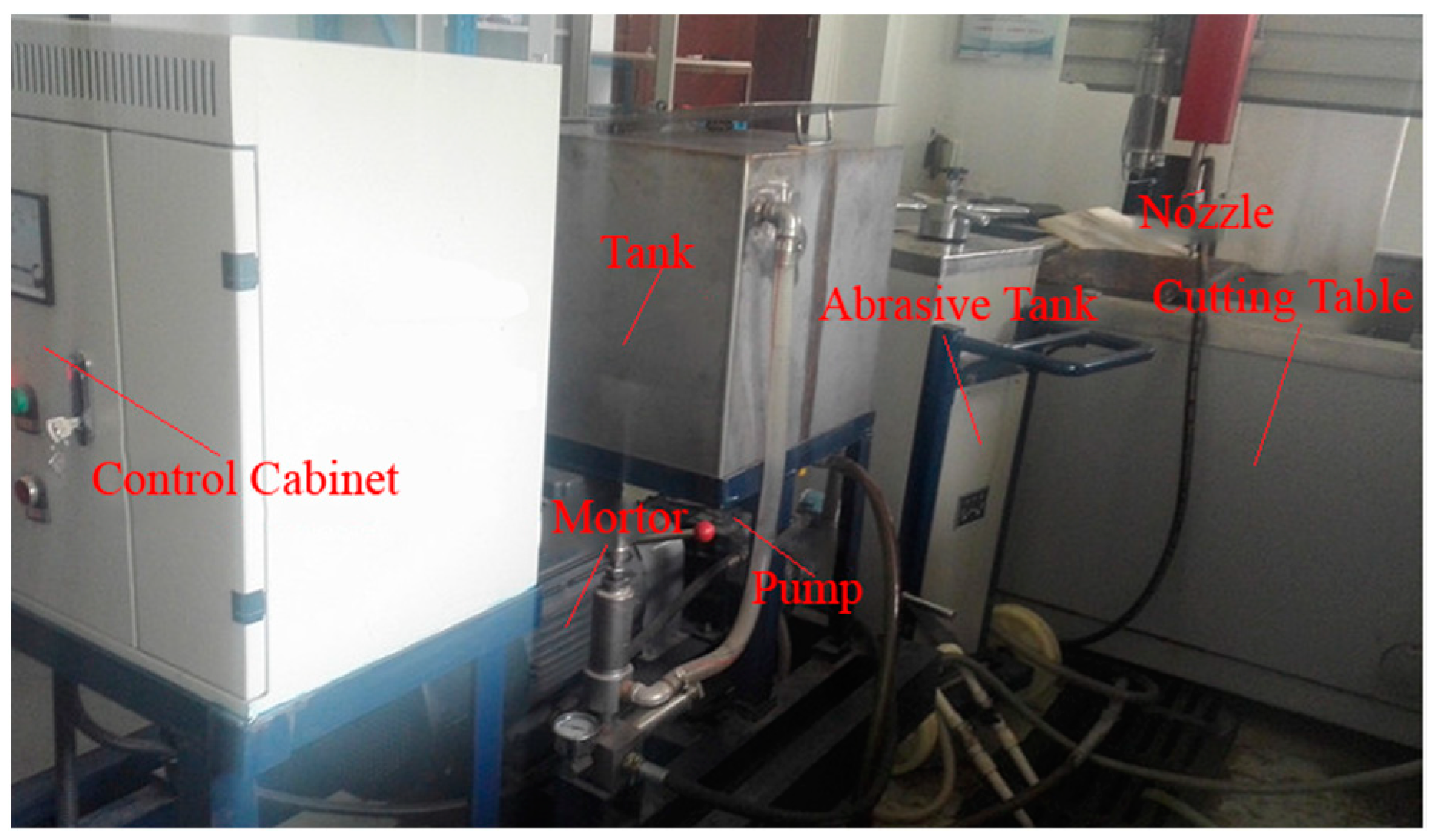
Figure 1 shows the ASJ generating system composed of a control cabinet, motor, tank, pump, abrasive tank, nozzle, and cutting table. High polymer solution in the tank was pressured by the pump driven by the motor and mixed with abrasive particles in the abrasive tank, finally forming the ASJ through the nozzle. The control cabinet can control the start-stop of the system and display the pressure and the motor speed in real time. The cutting table is a computer numerical control (CNC)machine tool, which can control the traverse speed accurately and adjust the distance between rock and nozzle.
As shown in
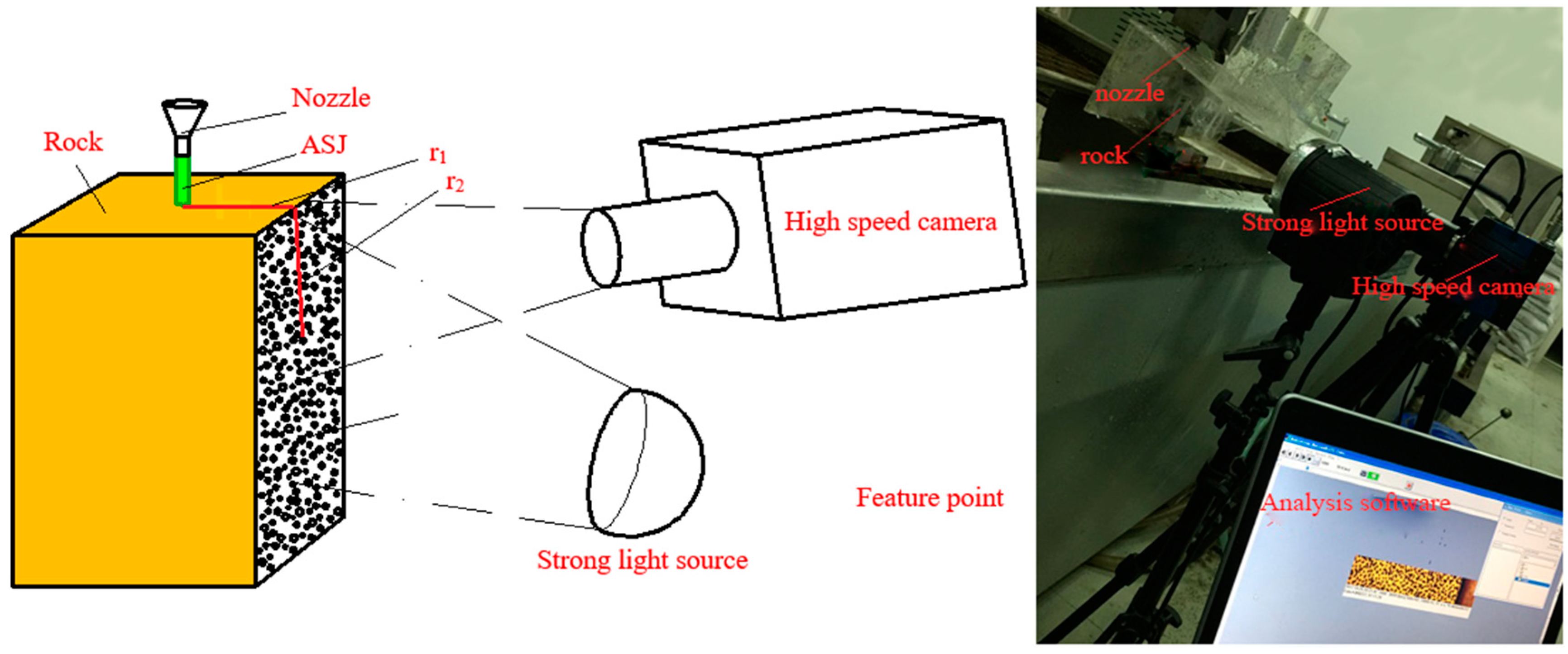
Figure 2, the non-contact strain measurement system consists of a high-speed camera, strong light source, and analysis software (DIC-3D, designed by University of Science and Technology of China (Hefei, China) and Southeast University (Nanjing, China)). Before the ASJ impacts rock, a picture of feature points on rock surface must be taken by the high-speed camera, which will be regarded as the reference image. Then, pictures of feature points on the rock surface were taken in real time by the high-speed camera in the process of the ASJ impacting the rock. Finally, analysis software was used to calculate the displacement of the same feature point between the experimental pictures and the reference image, obtaining the dynamic strain distribution on the rock surface.
The approach has two advantages. One is that the lack of contact between the measuring element and measured object can simplify the strain measuring process. The other is that a strain data of the whole measured surface can be obtained instead of data of a point. However, the approach also has a shortcoming as its accuracy will decrease when it is used to measure a strain less than 10 μm.
2.2. Experimental Subject
The rocks used in the experiment are gangue from Zhang Shuanglou coal mine in Xuzhou. Their physical properties have been obtained by a rock stress tester, which will directly affect the dynamic stress field of rock broken by ASJ. And the details are shown in
Table 1.
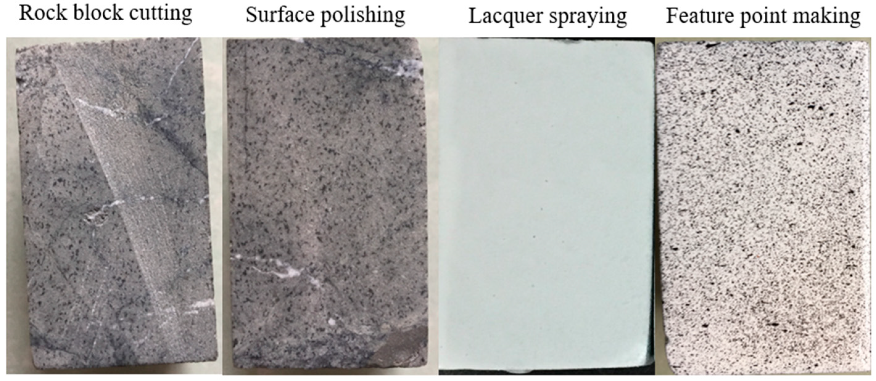
Before the dynamic strain measurement experiment, a series of processes for the rock surface must be implemented to reach the working requirement of the non-contact strain measurement system. As shown in
Figure 3, the process consists of rock block cutting, surface polishing, lacquer spraying, and making feature points. Finally, a cuboid rock block (30 × 30 × 50 mm) with enough feature points was obtained to be used in the dynamic strain measurement experiment.
2.3. Experimental Scheme
To study the effect of jet pressure on the dynamic strain distribution of rock broken by ASJ, the paper chose jet pressure as the experimental independent variable, with values of 10, 15, and 20 MPa. The other parameters were set up as constant and the details are shown in
Table 2.
In total, out three groups of experiments were carried out where rock was impacted by ASJ with three levels of jet pressure. In each group of experiments, frame per second (FPS) of the high-speed camera was set as 10,000, taking 1000 photos in 0.1 s. Every photo was calculated by the analysis software to a strain contour, which can show the dynamic strain distribution on the rock surface.
3. Experimental Data and Processing
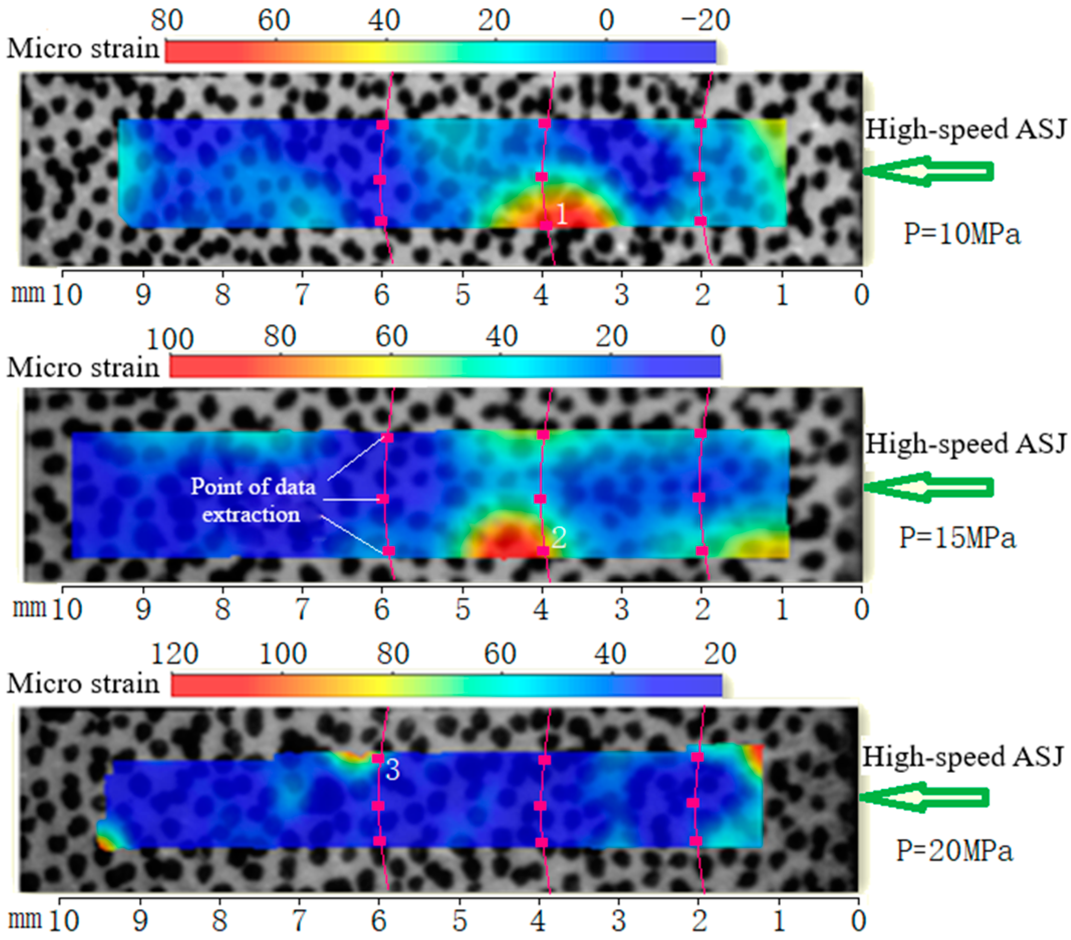
Figure 4 is the contour of rock strain calculated by the data analysis system, which can show the static strain distribution on rock surface. To get the rock dynamic strain, the paper chose nine data extraction points of rock strain in an experiment. All of the data extraction points are located on the intersection lines of the rock surface and three spheres, whose center is the intersection of the jet axis and top rock surface and diameters (
r) are 5.4 mm, 6.4 mm, and 7.8 mm. As shown in
Figure 2, with
r1 set as the constant (5 mm), the three sphere diameters correspond to the fixed values of
r2 (2 mm, 4 mm, and 6 mm).
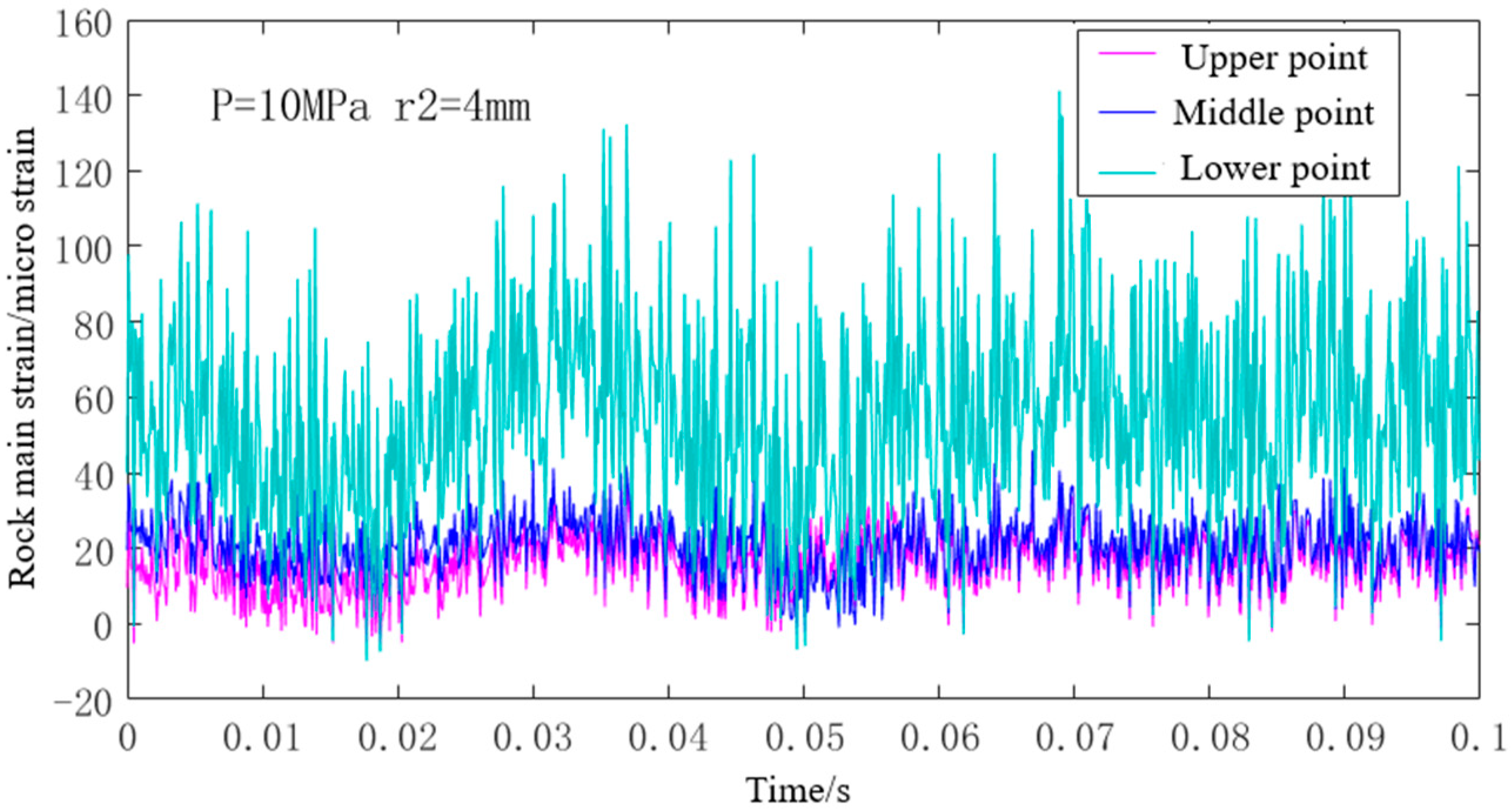
Figure 5 shows the dynamic rock strain of the three middle data extraction points under 10 MPa ASJ impacting. The dynamic value of rock strain has two characteristics. One of them is that the lower data extraction point is significantly greater than the middle and upper one in the value of rock strain, which is the result that the lower data extraction point locates in the strain concentration area (as shown in
Figure 4) caused by the inherent crack in the rock. The other characteristic is that the value of rock dynamic strain fluctuates wildly because there are many influencing factors in the experiment, such as motor vibration, noise vibration, and jet pressure fluctuation.
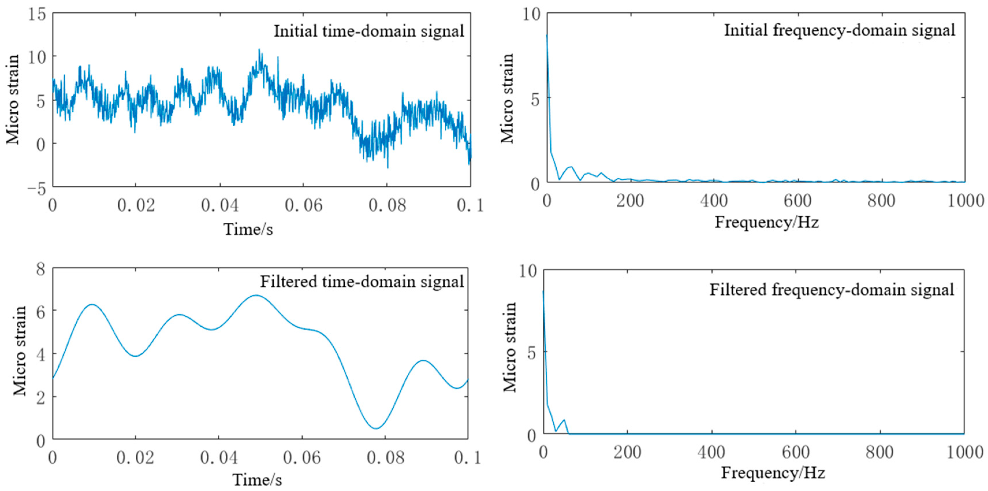
To study the universal distribution law of the dynamic strain, data processing of the rock strain was carried out. Firstly, the dynamic strain values at the data extraction point located in the strain concentration area must be deleted. Then, Fast Fourier Transformation (FFT) was used in filter processing of the rock dynamic strain data.
Figure 6 shows the filter processing of the rock dynamic strain data. In the first step, initial frequency-domain signal can be obtained by the FFT of the initial time-domain signal. In the second step, filtered frequency-domain signal can be obtained by deleting the high-frequency signal (larger than 50 Hz), which is caused by motor vibration, noise vibration, and jet pressure fluctuation. In the last step, filtered time-domain signal can be obtained by the Inverse Fast Fourier Transformation (IFFT) of the filtered frequency-domain signal.
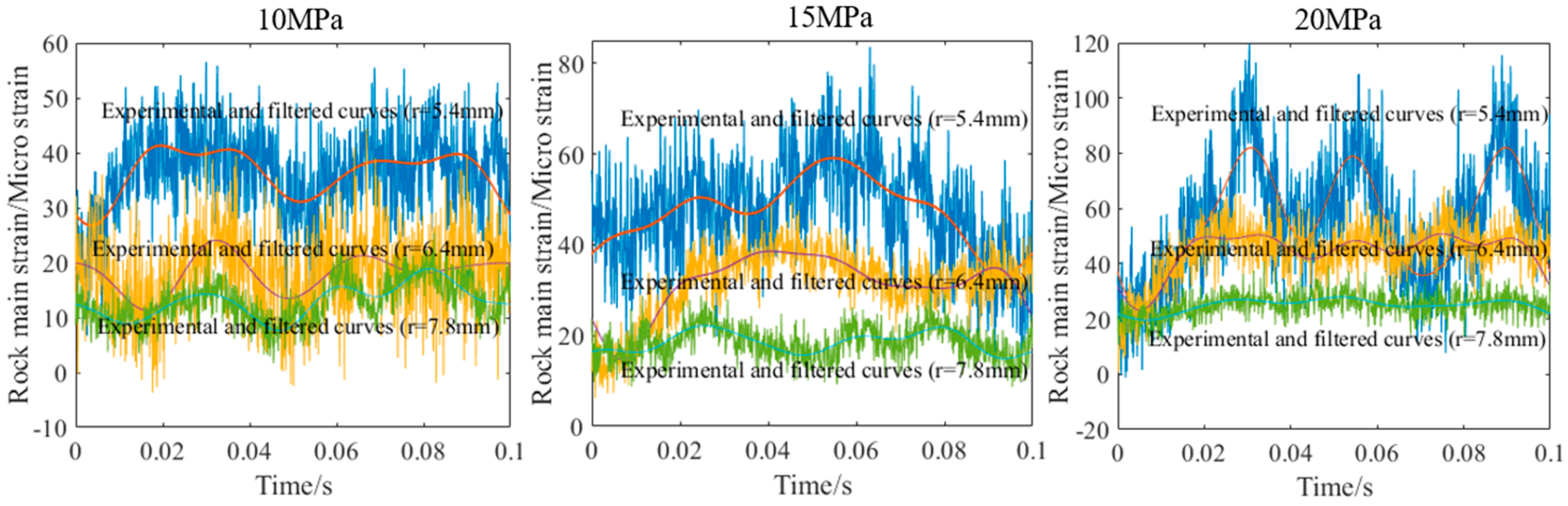
Figure 7 shows the data processing results of dynamic strain in rock broken by 10, 15, and 20 MPa ASJ. With rock impacted by ASJ under the same jet pressure, values of the dynamic strain decrease sharply with the increase of sphere diameter. When the sphere diameter keeps constant, values of the dynamic strain increase linearly with the increase of jet pressure. Moreover, the dynamic changes of strain in rock impacted by ASJ with the same pressure are similar, while the dynamic changes of strain in rock impacted by different pressures of ASJ are quite different. It reflects that rock dynamic strain distribution may be related to physical properties and fractures of rock.
4. Theoretical Analysis for the Dynamic Strain Distribution in Rock Broken by ASJ
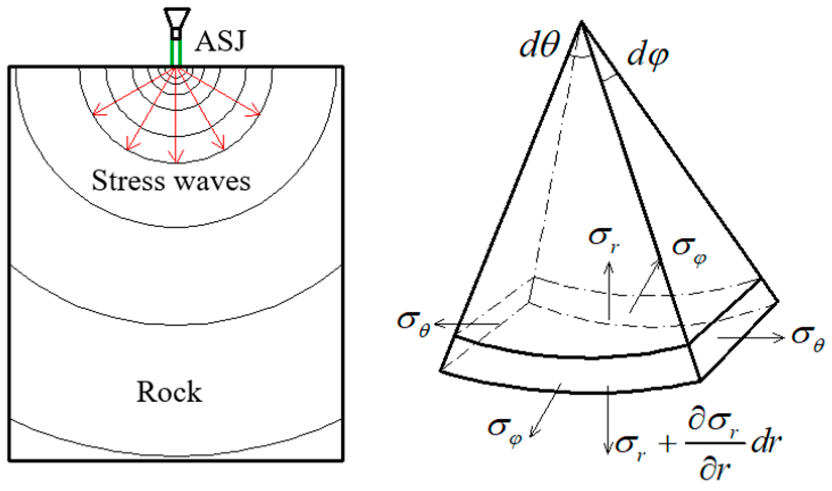
In this section, theoretical analysis for the dynamic strain distribution in rock broken by ASJ was performed, obtaining the propagation regularity of strain within the rock. With the impacting load of ASJ approximately acting at a point on the rock surface, the stress wave produced by ASJ impacting will be propagated within the rock in form of spherical wave [
18].
As shown in
Figure 8, the stress wave propagates within the rock in the form of a spherical wave, whose state parameters are related to the sphere radius (
r) and time (
t), and not related to the angles (
θ and
φ) in polar coordinates.
where,
is the rock radial displacement,
is the rock radial strain, and
is the rock tangential strain.
Assuming that rock is a standard elastomer with no initial crack, its constitutive equations can be expressed as follows
where,
is the Poisson ratio of the rock, and
E is the elastic modulus of the rock.
Based on the elastokinetics, the wave equation of the spherical wave in the rock can be expressed as follows [
19]
where,
is a potential function of the rock radial displacement.
is the velocity of the spherical wave in the rock, which is related to rock density
.
Solving the simultaneous equations (the five equations above), the paper can obtain the wave equation of stress wave in the rock impacted by ASJ. Outside the jet area, rock stress caused by the slurry jet impacting is much larger than that by the abrasive particles impacting [
20]. Therefore, with the impacting of abrasive particles ignored, the final stress wave equation was derived.
where,
,
,
.
In the formula, p0 is the pressure impacted on the rock, d is the jet diameter, and G is the shear modulus of the rock.
According to Equations (1), (4), and (6), the dynamic radial strain of rock can be calculated.
where,
,
.
With MATLAB software used for solving Equation (7) numerically, the dynamic strain of rock mass points with different radial distances can be obtained. In the formula solving process, the physical parameters are set as constant, the details of which are shown in
Table 1.
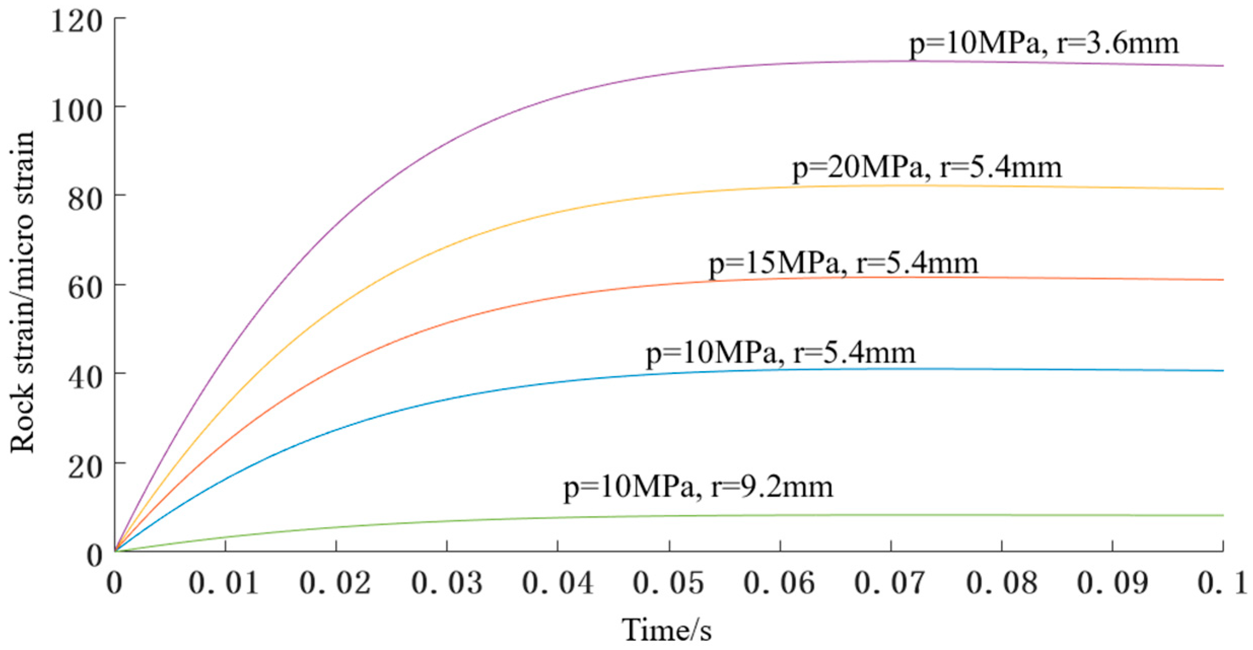
Figure 9 shows the numerical solution results of the formula, with different values chosen for the two parameters (jet pressure and propagation distance). It can be seen from the figure that the rock strain will increase to a maximum value with the increase of time, which can be regarded as a process of pressure increasing within the rock caused by ASJ impacting. Moreover, the maximum value of rock strain is proportional to jet pressure, while it is inversely proportional to the square of the propagation distance, which is in accordance with the experimental results.
Figure 10 also shows the time for rock strain to increase from zero to the maximum value is not affected very much by the jet pressure and propagation distance, which is related to the rock’s physical properties only.
5. Comparative Analysis of Theoretical and Experimental Results
In this section, theoretical and experimental results are compared and analyzed to obtain a unified dynamic strain distribution in rock broken by ASJ.
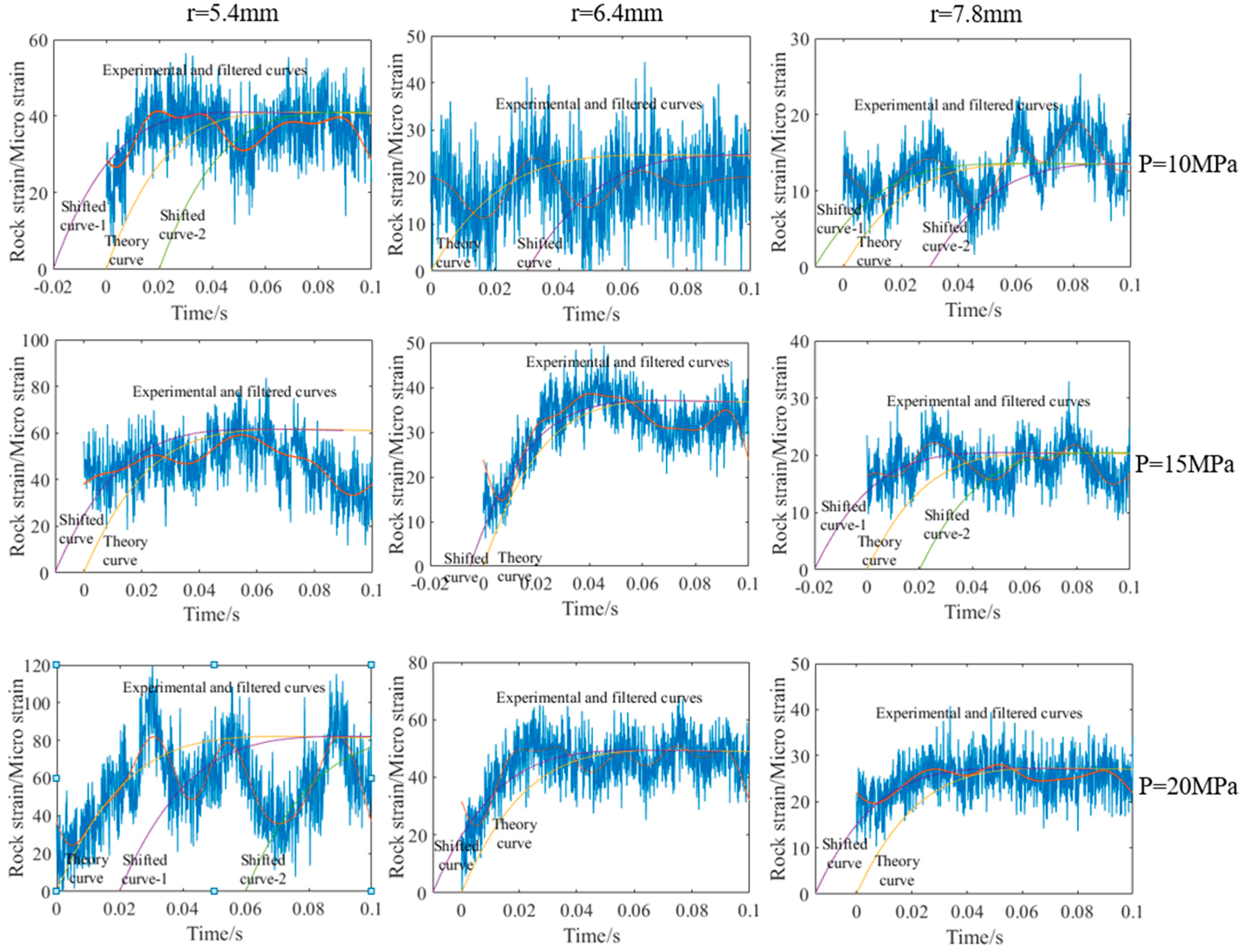
Figure 10 shows the comparison diagrams of the theoretical and experimental curves of the rock dynamic strain. The figure shows that there are two similarities and two differences between the theoretical curves and experimental curves. One of the similarities is that the maximum values of rock dynamic strain in the two curves are approximately equal under the same jet pressure and propagation distance. The other similarity is the effects of jet pressure and propagation distance on the maximum strain. The maximum value of rock strain increases linearly with the increase of jet pressure, while decreases sharply with the increase of propagation distance.
One of the differences is that the increase in the process of rock dynamic strain in the two curves cannot be fitted. The initial time point in the theoretical curves is the moment when the ASJ touches the rock, while the one in the experimental curves is not that moment. It is difficult to capture the strain of rock under impacting of the stable and high-speed ASJ at the initial time as the booster process of the ASJ system takes time. Therefore, the theoretical curves need to be shifted on the timeline to fit the experimental curves, which are shown in
Figure 10. The other difference is that the experimental curves are tortuous, while the theoretical curves are very smooth. The theoretical equation was established with effects of rock failure on dynamic strain ignored. However, in the process of strain measurement, the rock will break continuously, releasing the rock stress in an instant. When the breaking stops, rock stress will increase under the impacting of ASJ, forming the fluctuating rock dynamic stress finally. This also reflects that rock impacted by ASJ is broken in the form of stepped-failure indirectly.
Figure 10 also shows that theoretical curves shifted on the timeline are fitted appropriately with the experimental curves under various jet pressures and propagation distances, which can prove the correctness of theoretical and experimental results.

