Abstract
The general trend towards lightweight components and stronger but difficult to machine materials leads to a higher probability of vibrations in machining systems. Amongst them, chatter vibrations are an old enemy for machinists with the most dramatic cases resulting in machine-tool failure, accelerated tool wear and tool breakage or part rejection due to unacceptable surface finish. To avoid vibrations, process designers tend to command conservative parameters limiting productivity. Among the different machining processes, turning is responsible of a great amount of the chip volume removed worldwide. This paper reports some of the main efforts from the scientific literature to predict stability and to avoid chatter with special emphasis on turning systems. There are different techniques and approaches to reduce and to avoid chatter effects. The objective of the paper is to summarize the current state of research in this hot topic, particularly (1) the mechanistic, analytical, and numerical methods for stability prediction in turning; (2) the available techniques for chatter detection and control; (3) the main active and passive techniques.
1. Introduction
The study of chatter is closely related to the history of metal removal processes at the beginning of the 20th century. As early as 1907, Taylor, one of the fathers of modern machining, gives the first definition of chatter presenting this phenomenon as ‘perhaps the most obscure and difficult to ascertain’ [1]. However, it was not until midcentury when its main causes were identified. Among the different types of vibrations, chatter vibrations are defined as self-excited vibrations. When the tool/workpiece contact is not stiff enough, an oscillation is generated between them causing a distortion in the chip thickness parameter between two successive periods, t and t-T, where t is be the actual time and T the workpiece rotation period in the context of turning. In this way, the process itself produces feedback causing a vibration whose frequency is near, but not exactly, to the natural frequency of the system. As a result, waves between subsequent passes lead to unacceptable surface roughness or even out of tolerance workpieces [2,3]. To avoid vibration problems, attention must be paid at the very early stage of process planning. Particularly, the authors identified the following items as possible sources of vibrations: (1) cutting tool (grain size, geometry, coating and wear and their effect on cutting forces) [4,5]; (2) workpiece material (type of material, homogeneity, hard grains, porosity, defects) [6,7]; (3) machine-tool (machine, spindle, toolholder, tool overhang, clamping) [8].
In a pioneering study, Arnold [9] characterizes in a very complete way the origin and onset of vibrations in the cutting tool when machining steel. In this study, the origin of chatter is found at the forces sustained by the cutting process itself and not external forces. Together with Arnold, pioneers in detecting and studying chatter mechanisms were Tobias, Fishwick, and Polacek [10,11], who determined the presence of vibrations in machine tools due to the modulation or regeneration of the chip thickness. In low stiffness conditions, a feedback phenomenon turns current vibrations into vibrations of greater amplitude for the following period. At this time, Tobias [12] and Merritt [13] developed the basic dynamic theory for vibrations in machining, distinguishing between the different types of chatter, A or B, depending on the direction of the mode with respect to the plane where chip is formed.
Chatter emerged over the last 30 years as maybe the most challenging research topic in the machining of metallic components. This problem can be approached in many different ways. In References [14,15], the authors identified the most remarkable techniques including chatter stability prediction, chatter detection, and chatter control techniques.
Indeed, works from the literature for chatter suppression and control can be grouped into three approaches/strategies. The first technique consists of adequately selecting two cutting parameters from the stability lobe diagrams: (1) spindle speed, or more exactly cutting speed; (2) depth of cut. Regarding the feed parameter, this is often neglected during stability analysis and regenerative effect. The second method is to disrupt the regenerative effect by continuously varying machining parameters. Finally, the third method is to passively or actively alter the machine-tool dynamics to improve chatter-free available zones, usually by installing new devices, actuators, and sensors into the machine. These three methods are discussed separately within this work as follows.
2. Vibration Prediction in Turning Processes
Some of the most important models are listed in Appendix A. Tlusty [16] developed a one-dimensional orthogonal cutting model and obtained an approximate solution by projecting cutting forces and structural dynamics in the chip thickness direction. Later, Marui [17,18] carried out an experimental study where they concluded friction forces on the contact flank introduced energy on the cutting system and are responsible for maintaining the chatter vibration. Kaneko [19] proposed a 2D model for the prediction of chatter marks based on tests on a cantilevered piece. They were capable of relating the behavior of the rotating workpiece with a certain force, inversely proportional to the cutting speed and proportional to the velocity of the vibration, and studied the phase shift of the vibration. Minis [20] integrated the approach of the oriented transfer function with a cutting geometry in three dimensions but carried out the experimental validation for an orthogonal cutting. Then, he applied the Fourier series expansion to the periodic terms determining the Fourier coefficients of the corresponding milling transfer functions [21].
Rao and Shin [22] used the multidirectional approach of Budak-Altintas [23] applied to turning, including for the calculation of the chip section a coupling term between perpendicular directions. In a similar manner, Clancy and Shin [24] introduced wear and non-linearity of process damping. These studies complicate the modeling and resolution. At the same time, Ozdoganlar and Endres [25,26] presented an analytical model for calculating the chip section in tools with radii. Applying the above procedure, Reddy [27] obtained the stability maps for the turning of a piece of low stiffness. Later, Lazoglu et al. [28] proposed some analytical models in the time domain for the prediction of boring stability.
Budak and Ozlu [29,30,31] proposed a multi-dimensional frequency model that considered the effect of tool radius (Figure 1a). They discretized the chip section into small trapezoidal elements that resulted in a rise of the matrices’ dimension of the system to be solved. The lower the size of these elements, the more accurate the model is. However, computational costs are also increased. In that work, the authors considered interesting combinations of flexible tools and flexible workpieces in turning and boring operations considering tool radius. They found that inserts with bigger nose radii tend to reduce the stability limits in the turning/boring of flexible workpieces while the opposite is true when the tool is the most flexible element. When turning a flexible workpiece, the dynamics are only controlled by the transfer function of the tool in the feed direction, if the side cutting edge angle or the nose radius is zero. The workpiece dynamics can only affect the system if there exists a side cutting edge angle (or a nose radius). If the workpiece is the most flexible part, the stability limit is dramatically reduced. If the tool is the most flexible part, the workpiece can increase the stability limit. Chandiramani and Pothala [32] developed a very complete Two-Degree of Freedom (2-DOF) model for the cutting tool. They considered multiple time delays, cut-off possibility and process damping using a variation of the Runge–Kutta (RK) method. The chip thickness regenerative effect was studied including motions in tangential and radial directions. Urbikain et al. [33] calculated the stability lobes when chatter comes from a dominant mode in the tangential direction. They analyzed the coupling with feed direction in a cylindrical turning operation. Dassanayake and Suh [34] studied turning dynamics when chatter comes from the tool. In their original approach, the workpiece was modeled as three rotors (unmachined, being machined, and machined) connected by a flexible shaft. They used a 3D model to couple the equations of motion with a nonlinear cutting force and even considered whirling effect in their analysis.
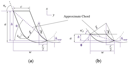
Figure 1.
Parameter of chip area from Eynian [37]. (a): a > rε·(1 − cos κr); (b) a < rε·(1 − cos κr).
Recently, Otto et al. [35] re-used the oriented transfer function concept from Tlusty [36] to solve stability in multi-dimensional cutting processes (with modes in different directions). These authors calculated the eigenvalues of the product transfer function and directional factors in a generalized model applicable to turning, milling, boring, or drilling. In the case of turning, they presented theoretical lobe diagrams depending on the rotation sense of the workpiece (clockwise and counterclockwise). These authors did not directly introduce the effect of the cutting speed in their analyses. Although the results were not validated, they expected different critical depths of cut, and chatter frequencies when turning with different rotational directions of the spindle.
In an attempt to improve the accuracy of frequency-based methods, Eynian [37] extended the force and stability models to more general tool geometries (variable position angle) and process damping (Figure 1b). Two approaches were compared: the first uses the hypothesis from Colwell [38] this is, the chip flow is normal to the line connecting the ends of the engaged cutting edge; the latter forming an angle φ with feed direction. Under this approach, the components Fn and Fr act parallel and normal to this direction; a second one based on Budak’s trapezoidal discretization approach. Both approaches show similar prediction errors in force, with errors lower than 15%.
Although these approaches were known since the end of the 60 s, a significant advance was recently made in the modeling of process damping. At low cutting speeds, the free chatter zone may increase under certain conditions. It is a complex phenomenon depending on a number of parameters: cutting speed; workpiece material; tool flank angle; dominant frequency and its relationship with cutting frequency, relative with cutting speed; time (feed and tool wear). Process damping is mathematically simple to model but leads to laborious experimental tests. In practice, the stability lobes lead to higher depths of cut in comparison with high cutting speeds [39,40]. Altintas et al. [41] identified the cutting coefficients including the process damping effect through a servo mechanism to control the oscillation frequency during experimental cutting tests. The study was applied to face turning but was later extended to the milling of low machinability materials [42,43]. Tyler et al. [44] developed a very complete stability model for multiple degrees of freedom turning. They considered the process damping force as a function of depth of cut, cutting speed, tool velocity, and an empirical component. They mounted a device to account for process damping effects and then validate the stability lobes in an exhaustive picture of the turning system.
Wang and Cleghorn [45] studied the effects of tool position, workpiece dimensions, and tool’s compliance on the stability charts. For model validation, they used a piece held at both ends, with good results applicable for roughing turning. They applied their calculations to experimental studies from other authors in the literature. Additionally, Sekar et al. [46] verified a 2-DOF model. Tool and workpiece were modeled as separate entities using single DOF models. Using their stability model for turning, stability under different operating conditions could be predicted, with and without the tailstock. Vela-Martinez et al. [47] proposed a model of various degrees of freedom taking into account the flexibility of the workpiece and tool separately or simultaneously. Estimations and trends were raised and observed, but the authors did not validate the models against experimental data (Figure 2). Chen and Tsao [48,49] developed 2-DOF models on flexible workpieces with and without the use of tailstock. They considered cases for face-turning and grooving were the workpiece was modeled as a Euler–Bernoulli type beam. The authors investigated the relationship between spindle speed and critical chip width under a variety of experimental setups. It was found that the critical chip width is always greater for the flexible case. At higher workpiece flexibility, a higher depth of cut is allowed.
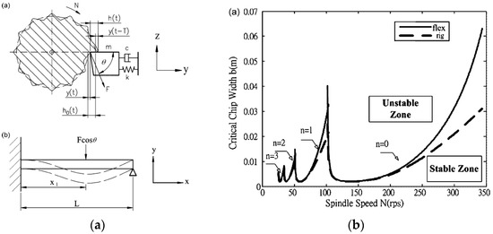
Figure 2.
(a) Scheme of the dynamic model for stability analysis of turning process considering workpiece flexibility; (b) stability lobes for workpiece considered as a rigid body and as a flexible body [48].
Other researchers analyzed complicated kinematics and complex effects. Yu and Shah [50] presented a method for chatter prediction in uniform and stepped workpieces. They determined the varying natural frequencies and varying mode shapes of workpieces during machining and gave some clues for a better understanding of gyroscopic and cross-coupling effects. Chanda and Dwivedy [51] used the method of multiple scales (MMS) to analyze nonlinear responses and the stability of the tool and workpiece. They considered the internal resonance and identified the most critical cutting parameters for chatter onset using time and frequency response curves from a theoretical point of view. Gyebroszki et al. [52] studied the stability of turning systems when chatter can be influenced by periodic chip formation. These authors combined a model for the regenerative effect and a model for chip formation. They showed the time scale due to chip segmentation is shorter than the time scale in more common turning systems. Due to nonlinear effects, the cutting coefficients are lower. Copenhaver et al. [53] analyzed and identified the stability of a modulated tool path (MTP) turning strategy. Under this technique, sinusoidal oscillations are superimposed to a common constant feed. For the validation tests, they performed longitudinal cuts in a tube of Aluminum 6061-T6 showing the capabilities of the process by means of broken chips. The results from their periodic sampling method were compared with the traditional frequency-domain method with good agreement.
Urbikain et al. [54] predicted the stability lobes for cases in turning where spindle speed (not cutting speed) is low, between 50 and 100 rpm such as horizontal lathes, using multi-mode analysis. They confirmed positively their numerical models (Figure 3b) but found difficulties for reasonable computation times. They proposed an alternative based on a version of dde23 from Matlab© to analyze chatter cases [55]. Otto et al. [56] made an approach to generalize turning cases were verification of their models was made with published experimental data from the literature. In a counterintuitive way, they stated that an increase in the stiffness of the workpiece can destabilize the tool modes producing an undesirable effect in the cutting stiffness and damping. Urbikain et al. [57] were able to predict the stability boundaries in the turning of flexible workpieces with inserts considering their radius. They extended the Chebyshev collocation method to account for a variable side cutting edge angle. For the experimental tests, they designed and prepared a mass-concentrated workpiece which was held between the chuck and the tailstock. These authors verified the capacity of the method for different dynamic conditions since the piece continuously loses mass.
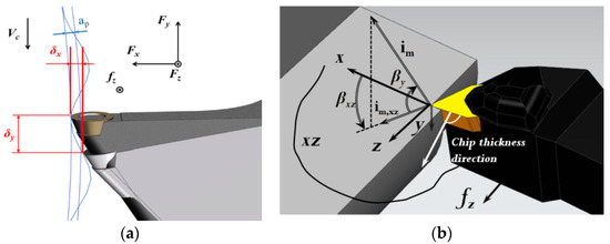
Figure 3.
(a) Chatter originated from a dominant mode in the tangential direction [33]; (b) multi-mode analysis of chatter in a cylindrical turning operation [55].
Later, Lu et al. [58] investigated the initiation mechanisms of chatter according to the position of the tool during the turning of flexible parts. Urbikain et al. [59] presented a stability prediction model for the interrupted turning of cylindrical pieces. Previously, polygons were milled to create different interruption levels. They observed the gain of stability as a direct effect, but not proportional to the cutting interruption degree. Palacios et al. [60] combined a simulated annealing technique (SA) with numerical methods to find the optimal cutting conditions in turning operations. They applied this methodology when turning difficult-to-cut materials such as nickel-based superalloys leading to 100 times faster computational times.
Qiu and Ge [61] presented an original representation of chatter problems considering modal parameters of tool and workpiece, tool angles, and modal angles. They developed the stability model based on the directions of motion velocity, motion displacement and related them with the generation of chatter marks. Jasiewicz and Miadlicki [62] applied the receptance coupling method for the estimation of the dynamical properties in a turning system with a compliant part. They obtained the cutting parameters with the aid of a program integrated in the CNC (Computer Numerical Control) system. In this way, the need of measurement equipment can be saved.
Recently, parallel turning has attracted the attention of researchers. In this turning operation two cutting inserts are engaged during cutting. Depending on how these tools are arranged, they can cut the same surface or not, leading to different configurations. For parallel turning centers, the tools are often fixed in independent turrets. Budak and Ozturk [63] published the first results regarding this technique. Their work showed that stability limits could be increased due to the dynamic coupling between the tools with respect to common turning systems. Later, these authors used a time- and frequency-domain model to study the influence of one tool on the other [64]. They depicted a view of the stability boundaries in terms of the frequency ratio between both tools. In close relation with the group from Budak, Reith et al. followed the investigation of the parallel turning technique in [65]. Here, they studied and validated the effects of changing the overhang of one of the tools over stability analysis. Afterwards, they analyzed the behavior of 2- and 3-DOF models using an artifact with two opposite tools [66]. They demonstrated the presence of non-proportional damping is responsible for an increase in chip width limit that allows a more robust prediction when using a 3-DOF model. Finally, Azvar and Budak [67] presented a multi-directional chatter stability model for different turning configurations (Figure 4) using frequency- and time-domain approaches. Using a model capable of including workpiece dynamics and tool geometry, results showed maximum stability is achieved when the total radial dynamic forces acting on the workpiece are minimized. In this way, inserts having smaller cutting coefficients, nose radius and side edge angle should be considered to reduce radial forces. Gouskov et al. [68] also investigated the stability of turning systems when different tools are simultaneously engaged in cutting. They presented a slightly different approach for the mathematical modeling, using a surface formation equation.
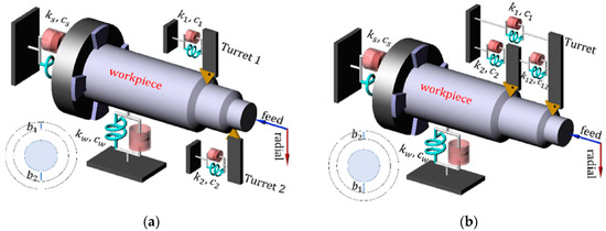
Figure 4.
Parallel turning operations [67]. (a) Tools mounted on different turrets; (b) tools mounted on the same turret.
The amount of literature regarding chatter gives a clear idea of the magnitude of the problem. In fact, after analyzing the numerous models and methods proposed in the past, the authors identified some key aspects: (1) the stability lobes are extremely important charts for improving productivity if these conditions are met: high spindle speeds; light materials; rough conditions and systems having low natural frequencies; (2) in any case, stability lobes are often related to local problems and need to be considered case by case. A more systematic application is desirable; (3) unless process damping emerged as a hot topic over the last decade, the developed models are to remain in the scientific domain rather than being used in practice due to their inherent complexity; (4) chatter is expected to continue to be present during the next years as new materials with better properties and lower machinability grades emerge and thinner workpieces are to be designed and produced.
3. Experimental Techniques
3.1. Experimental Techniques for Chatter Avoidance
This sub-section deals with experimental techniques regarding the modification of cutting parameters during machining (see Appendix B). For instance, spindle speed variation (SSV) technique can create a time-varying delay by creating distortions on chip thickness. As a result, new more favorable phase lags between inner and outer chip modulation reduce the chatter feedback mechanism [69,70,71,72]. There are different ways to vary the rotation speed of the head, but the most successful methods introduce a sinusoidal SSV, in which the speed of the spindle sinusoidally oscillates at a convenient frequency and amplitude [73,74].
The technique can be adapted to different cutting systems and dynamics. However, some areas in the stability lobe diagram that were previously stable can turn unstable when applying the variation. Another drawback of this technique is the high accelerations and decelerations in the spindle as well as the difficulty in tuning the frequency and amplitude of the variation.
The scientific literature first proposed the SSV technique to improve stability in milling processes [75]. Al-Regib et al. [76] presented a simple criterion for computing the optimal amplitude ratio and a heuristic criterion to facilitate the stabilization of the process. Zhang et al. [77] proposed a criterion to obtain optimal SSV amplitude based on energy analysis of the process. Additionally, they proposed a stability increment index (SII) of SSV with respect to constant spindle speed (CSS). The research group from Ideko-IK4 developed several works on the SSV technique applied to milling and grinding processes [78,79,80]. This technique can be difficult to apply in some cases such as low workpiece diameters. The amplitude of SSV is often related to the reference spindle speed and this parameter is constrained by the work material and workpiece diameter. For low workpiece diameters, high spindle speeds are needed to sustain adequate cutting speeds. Furthermore, the fluctuations of spindle speed lead to higher spindle speeds. Therefore, SSV is often run using G96 to set a constant surface speed and G50 (or G92) to allow a maximum spindle speed.
Insperger et al. [81] presented a complete formulation for the modelling of stability in turning and milling processes when using SSV for the semi-discretization method. However, some authors claim that SSV technique has a greater potential in processes with inherent lower cutting speeds such as turning rather milling. Wu et al. [82] designed the stability analysis of the tool using the discrete angle approach. Using this method, the independent variable is the workpiece angular position given by C-axis. They analyzed the effects of the variable speed machining on the noncircular turning stability and employed also a stability index criterion. Then, Wu and Chen [83] extended the previous analysis including a closed-loop dynamic model of the noncircular turning process. They observed by experimental results some improvements in the noncircular turning stability with constant and with variable spindle speeds.
Yilmaz et al. [84] showed a strong dampening and stabilization of the most unstable eigenmode in turning. Otto and Radons [85] presented an interesting modelling for the prediction of stability lobes with SSV technique in turning (Figure 5a). They introduced the guidelines to the implementation of this technique and stated that in turning processes it enables higher stable chip widths compared to milling processes. In addition, they proposed favorable conditions to control the maximum acceleration of the spindle speed. However, this study did not include experimental results. To overcome this, Urbikain et al. [86] studied the implementation of variable turning speeds during the turning of a piece and adapted the Chebyshev collocation method and the Homotopy Perturbation Method (HPM) for chatter onset prediction (Figure 5b). For validation, speed functions of sine-wave type were generated and verified using a laser tachometer. Good agreements were obtained in A and B chatter types. However, thermal aspects in the spindle speed were not considered in their analysis.
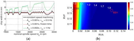
Figure 5.
(a) Stability lobes in turning with constant spindle speed and spindle speed variation (SSV) technique [85]; (b) optimum relationship between RVF (dimensionless spindle speed modulation frequency) and RVA (dimensionless spindle speed modulation amplitude) [86].
It is well known that the stability boundaries depend on the specific combination of spindle speed and uncut chip load, however, the single time-varying parameters (STVP) is an alternative technique that proved chatter suppression such as time-varying tool rake angle and time-varying federate. However, the authors pointed out that the robustness of this technique can be improved with the Multiple Time-Varying Parameter (MTVP) which offered chatter reductions close to 80% in some cases [87].
3.2. On-Line Chatter Classification, Detection, and Monitoring
Before it is fully evolved, chatter identification at early stages is crucial for its suppression or minimization in real-time applications. For this purpose, the time-efficiency method for monitoring of vibration or/and process signals is a key issue to be embedded in CNC controllers and other external devices. Several techniques have been used for chatter recognition based on pattern recognition, for instance via support vector machine [88], sensor-less based on indexes of power-factor theory [89], topological data analysis, or the use of regression neural networks where non-linear effects need to be faced [90].
Yamato et al. [89] proposed a sensor-less chatter detection method. To do so, they used a mechanical energy factor (MEF) and a mechanical power factor (MPF) which are useful when it comes tracking unstable cutting. These are indicators of the phase difference between the dynamic cutting force and velocity-displacement. From experimental tests in a precision lathe, the authors were capable of detecting chatter vibration under small number of computations. Later on, Khasawneh et al. [91] combined supervised machine learning with Topological Data Analysis (TDA) to obtain an indicator of chatter imminent presence. Under this approach, deterministic and stochastic turning models (with varying cutting coefficients) work together. Tansel [92] studied a tridimensional turning process by using neural network approach. Their model proved to represent nonlinear effects better than conventional time series models. Besides, the accuracy was better at higher cutting speeds, where the spacing between lobes is higher. Cherukuri et al. [93] applied and studied the behavior of applying an artificial neural network (ANN) when it comes to modelling stability in turning. The stability boundaries were used as a starting point for the creation of datasets to train the ANN. They found that the ANN was successful in predicting stability at >90% of the cases. Kumar and Singh [94] analyzed the relationship between cutting parameters and chatter degree using mathematical model of responses based on response surface methodology (RSM) and artificial neural network (ANN). The applied the Wavelet Transform to remove noise from the raw signals and showed that ANN was more reliable than RSM. To detect chatter severity, they obtained a chatter index. Shrivastava et al. [95] used a similar approach, they applied the wavelet transformation to denoise the raw signal, identification of chatter frequency, and calculation of chatter index. More recently, Kim and Ahmadi [96] proposed an operational modal analysis to predict chatter onset in turning processes. In this study, the authors used a stability margin of the process thus being able to predict chatter onset before the vibrations are unacceptable.
Aspects such as uncertainty or the relative randomness of process parameters was studied in some works. For instance, Liu et al. [97] calculated the reliability probability of chatter in a turning system. They used the first order second moment method (FOSM) and fourth moment method and compared with Monte Carlo simulation presenting a modified version of traditional stability lobes. For the experimental validation, they programmed increasing depths of cut to cross the stability boundary limits. Similarly, Huang et al. [98] obtained the width of cut to spindle speed ratio using Laplace transform making use of the Monte Carlo method and the advanced first order second moment method. They verified predictions with practical examples. Jimenez Cortadi et al. [99] applied the Linear Mixed Model (LMM) for chatter prediction as well as for wear prediction with a good accuracy. Tian [100] proposed a neural network analysis for detecting chatter vibration in turning. It was demonstrated that this approach was more efficient (fast) and reliable than the frequency domain method.
4. Passive and Active Suppression Techniques
Machining-tool manufacturers are required to produce a machine with high technological capabilities that improve the performance as industry demands higher quality and production. The application of precision processing has increased in recent years. For this reason, chatter avoidance has attracted the attention of researchers and industry conducting studies of the vibration phenomena using passive and active methods.
4.1. Passive Chatter Suppression Techniques
Passive chatter suppression methods focus on the implementation of external devices with the aim of modifying the stiffness or damping to the machine tool or the tool holder. Such methods are based on structure modifications or parameter optimization, which can be limited to physical restrictions.
Houck III et al. [101] tuned a holder for turning by varying the axial position of a sleeve. The modification of the tool-dynamics using dynamic vibration absorbers (DVA), tunable vibration absorbers (TVA) or tuned mass damper (TMD) have the purpose of increase the chatter boundaries. The DVA is a passive device with a spring-mass-damper attached to the tool holder (Figure 6), when tuned properly, it reduces the peak magnitude of the frequency response function. Moradi et al. [102] and Miguelez [103] applied a passive absorber to enhance the stability of a boring process. Saffury and Altus [104] optimized the mass and stiffness distribution yielding better chatter-resistance for turning bars. The scope of their study was to reduce chatter vibrations when the cutting tool is the most flexible part of the system. However, they did not present any experimental evidence to support their theoretical calculations.
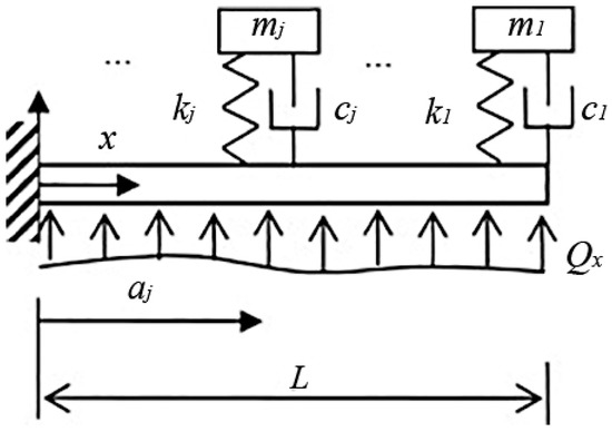
Figure 6.
Cantilever beam with attached spring-mass-damper system and distributed load [104].
Mohammadi et al. [105] modified the cutting system’s FRF (Frequency Response Function) and selecting proper dimensions for the assembly tool-toolholder-spindle. The methodology was proposed to increase and predict allowable stability for system where tool length can be varied or not. However, this technique was applied to milling systems.
4.2. Active Chatter Suppression Techniques
Active chatter suppression schemes, with suitable sensors/actuators installed on the spindle or tool holder, have demonstrated a potential performance improvement in the machine tool. This dynamic solution can adjust the parameters of the process depending on the feedback from the sensors. However, it usually requires high computing power and the effectiveness of the vibration suppression system depends on the strategies installed in the device controller.
An active dynamic absorber reduces vibration by using, for example, a piezoelectric actuator generating inertia forces that counteract the disturbance produced in the turning process [106]. Active damping dissipates energy once the vibration is measured and an actuator introduces a controlled force as a response. In a typical application a piezo actuator is bonded on the cutting tool. Yigit et al. [107] optimized a passive shunt electrical circuit, tuned according to the natural frequency of the cutting tool for damping optimization. In accordance with experimental modal testing, the stability limit is doubled when piezoelectric is used. Similarly, Martins da Silva et al. [108] demonstrated, in boring experiments with shunt circuits in both directions, the surface finish was improved with a roughness reduction of 30% on a peak-to-peak value.
Various active systems used to mitigate chatter are based on controllers with several inputs. Ma et al. [109] developed an active chatter suppression method that expands significantly the stability lobe diagram based on an active sliding mode controller that requires only a displacement measurement. This robust controller is suitable for non-linear uncertainties and disturbances such as permutations found in chatter vibrations. Liu et al. [110] analyzed the dynamic behavior of a constrained layer damping (CLD) tool holder that has frequency-dependent dynamics. These authors proved that the developed tool holder improves stable margins when the chatter frequency is far from the natural frequency.
Another type of device could be considered as a semi-active technique, it is based on a magnetorheological (MR) fluid-controlled boring bar (Figure 7) requiring lower energy. The MR fluid-controlled boring bar changes the stiffness of the tool by varying the strength of the applied magnetic field. Mei et al. [111] used a square wave current as a control signal showing that chatter could be significantly suppressed. For a high aspect ratio boring process, Som et al. [112] used an electromagnet to adjust the damping force of an MR damper showing an average attenuation of 30% in high-frequency ranges. When the rotational speed is low it is easier to suppress chatter by adjusting the natural frequency. For high rotational speeds an increased damping effect is advantageous [113].
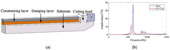
Figure 7.
(a) CLD tool holder in turning; (b) Frequency Response function with steel tool holder and CLD tool holder [110].
Recently a novel non-contact magnetic actuator [114] was developed to compensate the static deflection measured of a long boring bar. The bending mode was actively dampened, and the stiffness was increased for stable cutting at high depth cuts.
5. Practical Solutions for Industry
Although chatter has been known for some time and different tools have been developed to dominate and control surface quality, the use of these tools must be implemented on a case by case basis. If vibrations occur, the operator intuitively reduces the cutting parameters. This reduces productivity and is not always a guaranteed solution. To solve this gap between theoretical knowledge of vibrations and the industrial field, different simulation packages have been developed based on the measurement of some characteristic magnitudes during cutting.
- -
- CutPro/MachPro/ChatterPro/SpindlePro/NPro© (developed in the Manufacturing Laboratory of the British Columbia University, Vancouver under the direction of Professor Y. Altintas [115]): probably represents the best package to solve problems in machining as these functionalities deal with different machining aspects/problems. Cut Pro was the original software resulting in a wide family of products. It allows determining the best cutting parameters. As usual, prior to the simulations, the customer needs to identify the dynamic parameters (modal mass, damping ratio, and stiffness) of the tool/piece system as well as cutting coefficients. If one of the following elements is changed: (1) machine-tool and/or fixtures; (2) workpiece material (maybe the same material but from another batch); (3) cutting tool (overhang, toolholder, wear), the system needs to be characterized again because, in general, the cutting coefficients and the modal parameters will be different. To obtain the modal parameters, the software is capable of performing 3D modal analysis to filter and process the transfer functions and to obtain the fundamental modes. These are then used to simulate the stability lobes. SpindlePro is focused on the design and analysis of spindle systems; NPro is the implementation of CAM (Computer-Aided Manufacturing) and its combination with chatter requisites. The software is capable of simulating and optimizing tool paths.
- -
- Harmonizer© (developed in the MLI (Manufacturing Laboratories Inc.) of Las Vegas [116]): this software has been developed by years of experience for the control and reduction of vibrations in machining and leading to different packages: MilSim, CRAC (Chatter Avoidance and Recognition), MTDA (Machine Tool Dynamic Analyzer) and finally, Harmonizer©. Given a certain depth of cut and spindle speed, the analysis of the acoustic signal during machining allows to determine chatter frequency if the cut is unstable. In two or three iterations, the program is able to find a suitable spindle speed where the cut is free of chatter. If the initial depth of cut is too far from the final one or the modes are highly variable (magnitude and direction) over time such as in finishing operations, the system may have converging difficulties. Therefore, the system is more useful for 1-DOF systems and roughing operations. Recently, researchers presented BlueSwarf (MetalMAX©) which is an evolution for the rapid characterization of cutting process dynamics.
- -
- EMMATools from SMARTIbox© (Spindle Measuring and Analyzing Relevant Tool for Industry Box): this software emerged from the collaboration between the University of Nantes [117] and the Airbus company for the monitoring and preventive maintenance of high-speed spindles. Rotor displacements are measured, cutting frequency harmonics are analyzed through embedded sensors. By means of spindle monitoring, the stress levels and associated frequencies are controlled for the best benefit of spindle life, thus protecting the bearings.
- -
- Machining Navi© [118]: machine builders are also interested in selling machines with superior capacities. Machining Navi is one of the latest developments from Okuma for solving online chatter problems, it integrates a detection software within the numerical control of the machine itself. In this case, the chatter avoidance system uses the value of vibration captured by a sensor (amplitude and frequency) and other parameters (number of cutting edges, range of allowed speeds, threshold values for detection) to modify the spindle speed and the feed-axis for a more stable cut. The program can work on its own or be activated/deactivated by the operator and allows them to apply the speed before detecting chatter onset.
- -
- Makino: Makino Milling Machine (Tokyo, JP) patented a method [119] for chatter avoidance in machining systems (US 9.285,797 B2). This method was based on acquiring vibration data of the tool at a predetermined sampling period, then deciding as fast as possible whether the vibration data being processed matches an integral multiple of the calculated period or not.
- -
- Blue Swarf© [120,121] is a company that emerged from the expertise of Dr. Smith (University of North Carolina at Charlotte), Dr. Delio (President of Manufacturing Laboratories Inc. MLI), Mr. Barton (Founder and President of American Machinist), and Dr. Schmitz (University of North Carolina at Charlotte.). This software offers patches to solve vibrations problems in machining. Customers make use of individual dashboards for the identification of a particular machine tool-spindle-tool + material assembly. As a result, Blue Swarf makes a recommendation on the best cutting parameters. However, the software is more oriented to solve problems for milling rather than turning.
- -
- ChatterMaster [122,123]: from the University of Tarbes (ENIT), it follows the same approach by Pr. Altintas or MLI with Harmonizer. After extracting data of the machining system (spindle-tool material and cutting conditions) the software gives a recommendation for the best spindle speed to avoid chatter. Recently, ChatterMaster has developed a new module for chatter avoidance in turning operations.
6. Conclusions
Chatter is a known problem in turning and it can be approached in many different ways. This review resumes some of the efforts in the state of the art to detect, avoid, and reduce chatter vibrations and its harmful effects. First, the work was concentrated on analytical and numerical methods for stability prediction. However, whenever chatter is very complicated to model, active and passive techniques can be the answer. Therefore, a special section highlighted the milestones regarding these techniques.
After carefully examining research works, intense focus was and still is paid to mechanistic models. Numerical and mechanistic models are very popular and represent a relatively accurate way of predicting stability loss. In most cases, 1- or 2-DOF models establish the stability in turning processes. However, they lack generality. Research groups often face and solve a particular problem in a particular turning system. As chatter is a polyhedral problem, many authors tried to generalize the problem [116,117,118,119,120,121,122,123,124]. Systems having non-linear effects such as low cutting speeds, low machinability and hard materials, process damping, or wear are more complicated to model [125]. In these cases, chatter should be faced or completed through passive and active techniques. In recent years because of 4.0 Industry, acquiring and postprocessing many data sets at a high sampling rates is no longer an ideal task but a reality which should help designers to select suitable, productive but safe, cutting parameters.
As a general criterion, the stability of high speed turning and milling systems is investigated using a priori methods such as lobe diagrams. In this way, the spacing between low-order lobes can be advantageous for programming high depths of cut. However, this is not possible for turning processes and low spindle speeds, for instance when turning titanium or other low machinability alloys and superalloys. Chatter occurs at high order lobes where there is no spacing between lobes. Besides, process damping and nonlinearities hinder the modelling process. In those cases, practical techniques for chatter suppression such as SSV can be very interesting alternatives. While there is some reserve on the part of the industry when it comes to introducing spindle speed variation-SSV, machine-tool builders are beginning to sell machines with this capability.
Author Contributions
Conceptualization, methodology, software, and writing, G.U., D.O.; and A.B. Resources and supervision, L.N.L.d.L. and A.E.-Z.
Funding
Thanks are addressed to Basque country university excellence group IT1337-19. The authors wish to acknowledge also the financial support received from HAZITEK program, from the Department of Economic Development and Infrastructures of the Basque Government and from FEDER funds. This research was funded by Tecnológico de Monterrey through the Research Group of Nanotechnology for Devices Design, and by the Consejo Nacional de Ciencia y Tecnología (CONACYT), Project Numbers 242269, 255837, 296176, and the National Lab in Additive Manufacturing, 3D Digitizing and Computed Tomography (MADiT) LN299129.
Acknowledgments
Thanks are addressed to Eng. Luis Zabala from Kistler©, Endika Monge and Jon Méndez from Hoffmann© and Garikoitz Goikoetxea at the UPV/EHU, by their support and fruitful discussions during the years.
Conflicts of Interest
The authors declare no conflict of interest. The funding sponsors had no role in the design of the study; in the collection, analyses, or interpretation of data; in the writing of the manuscript, and in the decision to publish the results.
Appendix A. Publications Related to Chatter Stability Prediction

| Category | Publications | Number of Publications |
|---|---|---|
| Frequency-domain methods | [22,23,24,25,26,27,29,30,31,35,36,37,41,42,44,46,47,48,49,50,58,63,64,65,66] | 25 |
| Numerical methods giving time-domain solution | [28,32,34,43,45,51,52,54,67,68] | 10 |
| Numerical methods for stability prediction | [33,52,54,55,56,57,59,60,81,85,86] | 11 |
Appendix B. Publications Related to Experimental Techniques
| Category | Publications | Number of Publications |
|---|---|---|
| Techniques for chatter detection | [88,89,90,91,92,93,94,95,96,97,98,99,100] | 13 |
| Passive techniques for chatter avoidance | [101,102,103,104,105] | 5 |
| Active techniques for chatter avoidance | [106,107,108,109,110,111,112,113,114,115] | 10 |
References
- Taylor, F. On the Art of Cutting Metals; The American Society of Mechanical Engineers: New York, NY, USA, 1907. [Google Scholar]
- Yamane, Y.; Ryutaro, T.; Tadanori, S.; Martinez-Ramirez, I.; Keiji, Y. A new quantitative evaluation for characteristic of surface roughness in turning. Precis. Eng. 2017, 50, 20–26. [Google Scholar] [CrossRef]
- Nieslony, P.; Krolczyk, G.; Wojciechowski, S.; Chudy, R.; Zak, K.; Maruda, R. Surface quality and topographic inspection of variable compliance part after precise turning. Appl. Surf. Sci. 2018, 434, 91–101. [Google Scholar] [CrossRef]
- Asthakov, V.P.; Davim, J.P. Tools (Geometry and Material) and Tool Wear. In Machining; Springer: Berlin/Heidelberg, Germany, 2008; pp. 29–57. [Google Scholar]
- Asthakov, V.P.; Outeiro, J.C. Metal Cutting Mechanics, Finite Element Modelling. In Machining; Springer: Berlin/Heidelberg, Germany, 2008; pp. 1–27. [Google Scholar]
- Rech, J.; Hamdi, H.; Valette, S. Workpiece surface integrity. In Machining; Springer: Berlin/Heidelberg, Germany, 2008; pp. 59–96. [Google Scholar]
- Asthakov, V.P.; Davim, J.P. Machining of Hard Materials. In Machining; Springer: Berlin/Heidelberg, Germany, 2008; pp. 97–126. [Google Scholar]
- Lopez de Lacalle, L.N.; Lamikiz, A. Machine Tools for High Performance Machining; Springer: Berlin/Heidelberg, Germany, 2009. [Google Scholar]
- Arnold, R.N. The mechanism of tool vibration in the cutting of steel. Proc. Inst. Mech. Eng. 1946, 154, 261–284. [Google Scholar] [CrossRef]
- Tobias, S.A.; Fishwick, W. The chatter of lathe tools under orthogonal cutting conditions. Trans. ASME 1958, 80, 1079–1088. [Google Scholar]
- Tlusty, J.; Polacek, M. The stability of machine tools against self excited vibrations in machining. In Proceedings of the International Research in Production Engineering Conference, Pittsburgh, PA, USA, 9–12 September 1963; ASME: New York, NY, USA, 1963; pp. 465–474. [Google Scholar]
- Tobias, S.A. Machine Tool Vibration; Blackie and Sons Ltd.: Glasglow, UK, 1965. [Google Scholar]
- Meritt, H.E. Theory of self-excited machine–tool chatter. Trans. ASME 1965, 87, 447–454. [Google Scholar]
- Siddhpura, M.; Paurobally, R. A review of chatter vibration research in turning. Int. J. Mach. Tools Manuf. 2012, 61, 27–47. [Google Scholar] [CrossRef]
- Kashyzadeh, K.R.; Ostad-Ahmad-Ghorabi, M.J. Study of chatter analysis in turning tool and control methods—A Review. Int. J. Emerg. Technol. Adv. Eng. 2012, 2, 1–5. [Google Scholar]
- Tlusty, J. Dynamics of high-speed milling. J. Eng. Ind. 1986, 108, 59–67. [Google Scholar] [CrossRef]
- Marui, E.; Ema, S.; Kato, S. Chatter Vibration of Lathe Tools. Part 1: General Characteristics of Chatter Vibration. J. Eng. Ind. 1983, 105, 100–106. [Google Scholar] [CrossRef]
- Marui, E.; Ema, S.; Kato, S. Chatter vibration of lathe tools. Part 2: On the mechanism of exciting energy supply. Trans. ASME 1983, 105, 107–113. [Google Scholar] [CrossRef]
- Kaneko, T.; Sato, H.; Tani, Y.; O-Hori, M. Self-Excited Chatter and its Marks in Turning. J. Eng. Ind. 1984, 106, 222–228. [Google Scholar] [CrossRef]
- Minis, I.E.; Magrab, E.B.; Pandelidis, I.O. Improved Methods for the Prediction of Chatter in Turning, Part 3: A Generalized Linear Theory. J. Eng. Ind. 1990, 112, 28–35. [Google Scholar] [CrossRef]
- Yanushevsky, R.; Minis, I. A New Theoretical Approach for the Prediction of Machine Tool Chatter in Milling. J. Eng. Ind. 1993, 115, 1–8. [Google Scholar]
- Rao, B.C.; Shin, Y.C. A comprehensive dynamic cutting force model for chatter prediction in turning. Int. J. Mach. Tools Manuf. 1999, 39, 1631–1654. [Google Scholar] [CrossRef]
- Budak, E.; Altintas, Y. Analytical prediction of the chatter stability in milling Part I: General formulation. J. Dyn. Syst. Meas. Control 1998, 120, 22–30. [Google Scholar] [CrossRef]
- Clancy, B.E.; Shin, Y.C. A comprehensive chatter prediction model for face turning operation including tool wear effect. Int. J. Mach. Tools Manuf. 2002, 42, 1035–1044. [Google Scholar] [CrossRef]
- Ozdoganlar, O.B.; Endres, W.J. An analytical stability solution for the turning process with depth-direction dynamics and corner-radiused tooling. Trans. ASME 1998, 511–518. [Google Scholar]
- Ozdoganlar, O.B.; Endres, W.J. An analytical representation of chip Area for corner-radiused tools under depth-of-cut and feed variations. Trans. ASME 2000, 122, 660–665. [Google Scholar] [CrossRef]
- Reddy, R.G.; Ozdoganlar, O.B.; Kapoor, S.G.; Devor, R.E.; Liu, X. A Stability Solution for the Axial Contour-Turning Process. J. Manuf. Sci. Eng. 2002, 124, 581–587. [Google Scholar] [CrossRef]
- Lazoglu, I.; Atabey, F.; Altintas, Y. Dynamic of boring processes—Part III: Time domain. Int. J. Mach. Tools Manuf. 2002, 42, 1567–1576. [Google Scholar] [CrossRef]
- Ozlu, E.; Budak, E. Analytical Modeling of Chatter Stability in turning and boring operations—Part I: Model Development. J. Manuf. Sci. Eng. 2007, 129, 726–732. [Google Scholar] [CrossRef]
- Ozlu, E.; Budak, E. Analytical modeling of chatter stability in turning and boring operations, Part II: Experimental verification. J. Manuf. Sci. Eng. 2007, 129, 733–739. [Google Scholar] [CrossRef]
- Ozlu, E.; Budak, E. Comparison of one-dimensional oriented transfer function stability model vs. multi- dimensional stability model in turning operations. Int. J. Mach. Tools Manuf. 2007, 129, 726–732. [Google Scholar]
- Chandiramani, N.K.; Pothala, T. Dynamics of 2-DOF regenerative chatter during turning. J. Sound Vib. 2006, 290, 448–464. [Google Scholar] [CrossRef][Green Version]
- Urbikain, G.; Fernández, A.; De Lacalle, L.L.; Gutiérrez, M.; Pelayo, G.U.; De Lacalle, L.N.L. Stability lobes for general turning operations with slender tools in the tangential direction. Int. J. Mach. Tools Manuf. 2013, 67, 35–44. [Google Scholar] [CrossRef]
- Dassanayake, A.V.; Suh, C.S. On nonlinear cutting response and tool chatter in turning operation. Commun. Nonlinear Sci. Numer. Simul. 2008, 13, 979–1001. [Google Scholar] [CrossRef]
- Otto, A.; Rauh, S.; Kolouch, M.; Radons, G. Extension of Tlusty’s law for the identification of chatter stability lobes in multi-dimensional cutting processes. Int. J. Mach. Tools Manuf. 2014, 82, 50–58. [Google Scholar] [CrossRef]
- Tlusty, J. High-speed machining. CIRP Ann. 1993, 42, 733–738. [Google Scholar] [CrossRef]
- Eynian, M. Chatter Stability of Turning and Milling with Process Damping. Ph.D. Thesis, University of British Columbia, Vancouver, BC, Canada, 2010. [Google Scholar]
- Colwell, L.V. Predicting the Angle of Chip Flow for Single Point Cutting Tools. Trans. ASME 1954, 76, 199–204. [Google Scholar]
- Sisson, T.R.; Kegg, R.L. An explanation of low-speed chatter effects. J. Eng. Ind. 1969, 91, 951–958. [Google Scholar] [CrossRef]
- Tlusty, J. Analysis of state of research in cutting dynamic. CIRP Ann. 1978, 27, 583–589. [Google Scholar]
- Altintas, Y.; Eynian, M.; Onozuka, H. Identification of dynamic cutting force coefficients and chatter stability with process damping. CIRP Ann. 2008, 57, 371–374. [Google Scholar] [CrossRef]
- Budak, E.; Tunc, L.T. A New Method for Identification and Modeling of Process Damping in Machining. J. Manuf. Sci. Eng. 2009, 131, 051019. [Google Scholar] [CrossRef]
- Ahmadi, K.; Ismail, F. Experimental investigation of process damping non linearity in machining chatter. Int. J. Mach. Tools Manuf. 2010, 50, 1006–1014. [Google Scholar] [CrossRef]
- Tyler, C.T.; Troutman, J.R.; Schmitz, T.L. A coupled dynamics, multiple degree of freedom process damping model, Part 1: Turning. Precis. Eng. 2016, 46, 65–72. [Google Scholar] [CrossRef]
- Wang, Z.; Cleghorn, W. Stability analysis of spinning stepped-shaft workpieces in a turning process. J. Sound Vib. 2002, 250, 356–367. [Google Scholar] [CrossRef]
- Sekar, M.; Srinivas, J.; Kotaiah, K.; Yang, S. Stability analysis of turning process with tailstock-supported workpiece. Int. J. Adv. Manuf. Technol. 2009, 43, 862–871. [Google Scholar] [CrossRef]
- Vela-Martínez, L.; Jáuregui-Correa, J.C.; Rubio-Cerda, E.; Herrera-Ruiz, G.; Lozano-Guzmán, A. Analysis of compliance between the cutting tool and the workpiece on the stability of a turning process. Int. J. Mach. Tools Manuf. 2008, 48, 1054–1062. [Google Scholar] [CrossRef]
- Chen, C.; Tsao, Y. A stability analysis of turning a tailstock supported flexible work-piece. Int. J. Mach. Tools Manuf. 2006, 46, 18–25. [Google Scholar] [CrossRef]
- Chen, C.-K.; Tsao, Y.-M. A stability analysis of regenerative chatter in turning process without using tailstock. Int. J. Adv. Manuf. Technol. 2006, 29, 648–654. [Google Scholar] [CrossRef]
- Yu, S.D.; Shah, V. Theoretical and Experimental Studies of Chatter in Turning for Uniform and Stepped Workpieces. J. Vib. Acoust. 2008, 130, 061005. [Google Scholar] [CrossRef]
- Chanda, A.; Dwivedy, S.K. Nonlinear dynamic analysis of flexible workpiece and tool in turning operation with delay and internal resonance. J. Sound Vib. 2018, 434, 358–378. [Google Scholar] [CrossRef]
- Gyebrószki, G.; Bachrathy, D.; Csernák, G.; Stepan, G. Stability of turning processes for periodic chip formation. Adv. Manuf. 2018, 6, 345–353. [Google Scholar] [CrossRef]
- Copenhaver, R.; Schmitz, T.; Smith, S. Stability analysis of modulated tool path turning. CIRP Ann. 2018, 67, 49–52. [Google Scholar] [CrossRef]
- Urbikain, G.; Campa, F.J.; Zulaika, J.-J.; De Lacalle, L.-N.L.; Alonso, M.-A.; Collado, V. Preventing chatter vibrations in heavy-duty turning operations in large horizontal lathes. J. Sound Vib. 2015, 340, 317–330. [Google Scholar] [CrossRef]
- Urbikain, G.; Olvera, D.; De Lacalle, L.N.L.; Elías-Zúñiga, A.; Pelayo, G.U. Stability and vibrational behaviour in turning processes with low rotational speeds. Int. J. Adv. Manuf. Technol. 2015, 80, 871–885. [Google Scholar] [CrossRef]
- Otto, A.; Khasawneh, F.A.; Radons, G. Position-dependent stability analysis of turning with tool and workpiece compliance. Int. J. Adv. Manuf. Technol. 2015, 79, 1453–1463. [Google Scholar] [CrossRef]
- Urbikain, G.; De Lacalle, L.L.; Campa, F.J.; Fernández, A.; Elias, A.; De Lacalle, L.N.L. Stability prediction in straight turning of a flexible workpiece by collocation method. Int. J. Mach. Tools Manuf. 2012, 54, 73–81. [Google Scholar] [CrossRef]
- Lu, K.; Lian, Z.; Gu, F.; Liu, H. Model-based chatter stability prediction and detection for the turning of a flexible workpiece. Mech. Syst. Signal Process. 2018, 100, 814–826. [Google Scholar] [CrossRef]
- Urbikain, G.; De Lacalle, L.L.; Fernández, A.; De Lacalle, L.N.L. Regenerative vibration avoidance due to tool tangential dynamics in interrupted turning operations. J. Sound Vib. 2014, 333, 3996–4006. [Google Scholar] [CrossRef]
- Palacios, J.; Olvera, D.; Urbikain, G.; Elías-Zúñiga, A.; Martínez-Romero, O.; De Lacalle, L.L.; Rodríguez, C.; Martínez-Alfaro, H. Combination of simulated annealing and pseudo spectral methods for the optimum removal rate in turning operations of nickel-based alloys. Adv. Eng. Softw. 2018, 115, 391–397. [Google Scholar] [CrossRef]
- Qiu, J.; Ge, R. An improved stability lobe and turning chatter characteristic investigation. Int. J. Mech. Sci. 2018, 149, 338–348. [Google Scholar] [CrossRef]
- Jasiewicz, M.; Miadlicki, K. Implementation of an algorithm to prevent chatter vibration in a CNC system. Materials 2019, 12, 3193. [Google Scholar] [CrossRef] [PubMed]
- Budak, E.; Ozturk, E. Dynamics and stability of parallel turning operations. CIRP Ann. 2011, 60, 383–386. [Google Scholar] [CrossRef]
- Ozturk, E.; Comak, A.; Budak, E. Tuning of tool dynamics for increased stability of parallel (simultaneous) turning processes. J. Sound Vib. 2016, 360, 17–30. [Google Scholar] [CrossRef]
- Reith, M.J.; Bachrathy, D.; Stepan, G. Optimal detuning of a parallel turning system—Theory and experiments. J. Dyn. Sys. Meas. Control 2017, 139, 014503. [Google Scholar] [CrossRef]
- Reith, M.J.; Stepan, G. Effect of non-proportional damping on the dynamics and stability of multi-cutter turning systems. Int. J. Mach. Tools Manuf. 2017, 117, 23–30. [Google Scholar] [CrossRef]
- Azvar, M.; Budak, E. Multi-dimensional chatter stability for enhanced productivity in different parallel turning strategies. Int. J. Mach. Tools Manuf. 2017, 123, 116–128. [Google Scholar] [CrossRef]
- Gouskov, A.M.; Guskov, M.A.; Tung, D.D.; Panovko, G.Y. Modeling and Investigation of the Stability of a Multicutter Turning Process by a Trace. J. Mach. Manuf. Reliab. 2018, 47, 317–323. [Google Scholar] [CrossRef]
- Inamura, T.; Sata, T. Stability analysis of cutting under varying spindle speed. CIRP Ann. 1974, 23, 119–120. [Google Scholar]
- Takemura, T.; Kitamura, T.; Hoshi, T.; Okushimo, K. Active suppression of chatter by programmed variation of spindle speed. CIRP Ann. 1974, 23, 121–122. [Google Scholar]
- Sexton, J.; Milne, R.; Stone, B. A stability analysis of single-point machining with varying spindle speed. Appl. Math. Model. 1977, 1, 310–318. [Google Scholar] [CrossRef]
- Hoshi, T.; Sakisaka, N.; Moriyama, I.; Sato, M. Study for practical application of fluctuating speed cutting for regenerative chatter control. CIRP Ann. 1977, 25, 175–179. [Google Scholar]
- Tsao, T.; McCarthy, M.; Kapoor, S.G. A New Approach to Stability Analysis of Variable Speed Machining Systems. Int. J. Mach. Tools Manuf. 1933, 33, 791–808. [Google Scholar] [CrossRef]
- Soliman, E.; Ismail, F. Chatter Suppression by Adaptive Speed Modulation. Int. J. Mach. Tools Manuf. 1977, 37, 355–369. [Google Scholar] [CrossRef]
- Jayaram, S.; Kapoor, S.G.; DeVor, R.E. Analytical stability analysis of variable spindle speed machining. J. Manuf. Sci. Eng. 2000, 122, 391–397. [Google Scholar] [CrossRef]
- Al-Regib, E.; Ni, J.; Lee, S.-H. Programming spindle speed variation for machine tool chatter suppression. Int. J. Mach. Tools Manuf. 2003, 43, 1229–1240. [Google Scholar] [CrossRef]
- Zhang, H.H.; Jackson, M.J.; Ni, J. Spindle speed variation method for regenerative machining chatter control. Int. J. Nanomanuf. 2009, 3, 73–99. [Google Scholar] [CrossRef]
- Zatarain, M.; Bediaga, I.; Muñoa, J.; Lizarralde, R. Stability of milling processes with continuous spindle speed variation: Analysis in the frequency and time domains, and experimental correlation. CIRP Ann. 2008, 57, 379–384. [Google Scholar] [CrossRef]
- Bediaga, I. Regenerative Chatter Suppression by Means of Variable Spindle Speed. Ph.D. Thesis, Dpt. of Mechanical Engineering, UPV/EHU, Bilbao, Spain, 2009. [Google Scholar]
- Barrenetxea, D.; Marquinez, J.; Bediaga, I.; Uriarte, L. Continuous workpiece speed variation (CWSV): Model based practical application to avoid chatter in grinding. CIRP Ann. 2009, 58, 319–322. [Google Scholar] [CrossRef]
- Insperger, T.; Stepan, G. Semi-Discretization for Time-Delay Systems: Stability and Engineering Applications; Springer: London, UK, 2010. [Google Scholar]
- Wu, D.; Chen, K.; Wang, X. An investigation of practical application of variable spindle speed machining to noncircular turning process. Int. J. Adv. Manuf. Technol. 2009, 44, 1094–1105. [Google Scholar] [CrossRef]
- Wu, D.; Chen, K. Chatter suppression in fast tool servo-assisted turning by spindle speed variation. Int. J. Mach. Tools Manuf. 2010, 50, 1038–1047. [Google Scholar] [CrossRef]
- Yilmaz, A.; Al Regib, E.; Ni, J. Machine Tool Chatter Suppression by Multi Level Random Spindle Speed Variation. J. Manuf. Sci. Eng. 2002, 124, 208–216. [Google Scholar] [CrossRef]
- Otto, A.; Radons, G. Application of spindle speed variation for chatter suppression in turning. CIRP J. Manuf. Sci. Technol. 2013, 6, 102–109. [Google Scholar] [CrossRef]
- Urbikain, G.; Olvera, D.; De Lacalle, L.L.; Elías-Zúñiga, A. Spindle speed variation technique in turning operations: Modeling and real implementation. J. Sound Vib. 2016, 383, 384–396. [Google Scholar] [CrossRef]
- Yang, F.; Zhang, B.; Yu, J. Chatter suppression with multiple time-varying parameters in turning. J. Mater. Process. Technol. 2003, 141, 431–438. [Google Scholar] [CrossRef]
- Yao, Z.; Mei, D.; Chen, Z. On-line chatter detection and identification based on wavelet and support vector machine. J. Mater. Process. Technol. 2010, 210, 713–719. [Google Scholar] [CrossRef]
- Yamato, S.; Hirano, T.; Yamada, Y.; Koike, R.; Kakinuma, Y. Sensor-less on-line chatter detection in turning process based on phase monitoring using power factor theory. Precis. Eng. 2018, 51, 103–116. [Google Scholar] [CrossRef]
- Khasawneh, F.A.; Munch, E. Chatter detection in turning using persistent homology. Mech. Syst. Signal Process. 2016, 70, 527–541. [Google Scholar] [CrossRef]
- Khasawneh, F.A.; Munch, E.; Perea, J.A. Chatter Classification in Turning using Machine Learning and Topological Data Analysis. IFAC-PapersOnLine 2018, 51, 195–200. [Google Scholar] [CrossRef]
- Tansel, I.N. Modelling 3-D cutting dynamics with neural networks. Int. J. Mach. Tools Manuf. 1992, 32, 829–853. [Google Scholar] [CrossRef]
- Cherukuri, H.; Perez-Bernabeu, E.; Selles, M.; Schmitz, T.L. A neural network approach for chatter prediction in turning. Procedia Manuf. 2019, 34, 885–892. [Google Scholar] [CrossRef]
- Kumar, S.; Singh, B. Prediction of tool chatter in turning using RSM and ANN. Mater. Today Proc. 2018, 5, 23806–23815. [Google Scholar] [CrossRef]
- Shrivastava, Y.; Singh, B.; Sharma, A. Identification of Chatter in Turning Operation using WD and EMD. Mater. Today Proc. 2018, 5, 23917–23926. [Google Scholar] [CrossRef]
- Kim, S.; Ahmadi, K. Estimation of vibration stability in turning using operational modal analysis. Mech. Syst. Signal Process. 2019, 130, 315–332. [Google Scholar] [CrossRef]
- Liu, Y.; Li, T.-X.; Liu, K.; Zhang, Y.-M. Chatter reliability prediction of turning process system with uncertainties. Mech. Syst. Signal Process. 2016, 66, 232–247. [Google Scholar] [CrossRef]
- Huang, X.; Hu, M.; Zhang, Y.; Lv, C. Probabilistic analysis of chatter stability in turning. Int. J. Adv. Manuf. Technol. 2016, 87, 3225–3232. [Google Scholar] [CrossRef]
- Cortadi, A.J.; Irigoien, I.; Boto, F.; Sierra, B.; Suarez, A.; Galar, D. A statistical data-based approach to instability detection and wear prediction in radial turning processes. Ekspolatacja Niezawodn. Maint. Reliab. 2018, 20, 405–412. [Google Scholar] [CrossRef]
- Tian, A.-H.; Fu, C.-B.; Su, X.-Y.; Yau, H.-T. Lathe tool chatter vibration diagnostic using general regression neural network based on Chua’s circuit and fractional-order Lorenz master/slave chaotic system. J. Low Freq. Noise Vib. Act. Control 2018, 38, 953–966. [Google Scholar] [CrossRef]
- Houck, L.; Schmitz, T.L.; Smith, K.S. A tuned holder for increased boring bar dynamic stiffness. J. Manuf. Process. 2011, 13, 24–29. [Google Scholar] [CrossRef]
- Moradi, H.; Bakhtiari-Nejad, F.; Movahhedy, M. Tuneable vibration absorber design to suppress vibrations: An application in boring manufacturing process. J. Sound Vib. 2008, 318, 93–108. [Google Scholar] [CrossRef]
- Miguélez, M.H.; Rubio, L.; Loya, J.A.; Fernández-Sáez, J. Improvement of chatter stability in boring operations with assive vibration absorbers. Int. J. Mech. Sci. 2010, 52, 1376–1384. [Google Scholar] [CrossRef]
- Saffury, J.; Altus, E. Chatter resistance of non-uniform turning bars with attached dynamic absorbers—Analytical approach. J. Sound Vib. 2010, 329, 2029–2043. [Google Scholar] [CrossRef]
- Mohammadi, Y.; Azvar, M.; Budak, E. Suppressing vibration modes of spindle-holder-tool assembly through FRF modification for enhanced chatter stability. CIRP Ann. 2018, 67, 397–400. [Google Scholar] [CrossRef]
- Tewani, S.G.; Rouch, K.E.; Walcott, B.L. A study of cutting process stability of a boring bar with active dynamic absorber. Int. J. Mach. Tools Manuf. 1995, 35, 91–108. [Google Scholar] [CrossRef]
- Yigit, U.; Cigeroglu, E.; Budak, E. Chatter reduction in boring process by using piezoelectric shunt damping with experimental verification. Mech. Syst. Signal Process. 2017, 97, 312–321. [Google Scholar] [CrossRef]
- Martins da Silva, M.; Sardi, V.G.; Sérgio, V.P.; Teixeria, C.R. Experimental results on chatter reduction in turning through embedded piezoelectric material and passive shunt circuits. Mechatronics 2015, 29, 78–85. [Google Scholar] [CrossRef]
- Ma, H.; Wu, J.; Yang, L.; Xiong, Z. Active chatter suppression with displacement-only measurement in turning process. J. Sound Vib. 2017, 401, 255–267. [Google Scholar] [CrossRef]
- Liu, Y.; Liu, Z.; Song, Q.; Wang, B. Analysis and implementation of chatter frequency dependent constrained layer damping tool holder for stability improvement in turning process. J. Mater. Process. Technol. 2019, 266, 687–695. [Google Scholar] [CrossRef]
- Mei, D.; Yao, Z.; Kong, T.; Chen, Z. Parameter optimization of time-varying stiffness method for chatter suppression based on magnetorheological fluid-controlled boring bar. Int. J. Adv. Manuf. Technol. 2010, 46, 1071–1083. [Google Scholar] [CrossRef]
- Som, A.; Kim, D.-H.; Son, H. Semiactive Magnetorheological Damper for High Aspect Ratio Boring Process. IEEE/ASME Trans. Mechatron. 2015, 20, 5. [Google Scholar] [CrossRef]
- Mei, D.; Kong, T.; Shih, A.J.; Chen, Z. Magnetorheological fluid-controlled boring bar for chatter suppression. J. Mater. Process. Technol. 2009, 209, 1861–1870. [Google Scholar] [CrossRef]
- Lu, X.; Chen, F.; Altintas, Y. Magnetic actuator for active damping of boring bars. CIRP Ann. 2014, 63, 369–372. [Google Scholar] [CrossRef]
- Manufacturing Automation Laboratories. Available online: https://www.malinc.com/ (accessed on 22 July 2019).
- MetalMax, Manufacturing Laboratories Inc. Available online: https://www.mfg-labs.com/ (accessed on 22 July 2019).
- Analyse Vibratoire en Usinage. Available online: http://www.aic-et.fr/page-182-analyse-vibratoire-en-usinage-emmatools.html (accessed on 22 October 2019).
- Machining Navi, Okuma. Available online: https://www.okuma.com/machining-navi (accessed on 22 October 2019).
- Kondo, E. Chatter Vibration Detection Method, Chatter Vibration Avoidance Method, and Machine Tool. Patent No. US 9.285,797 B2, 15 March 2011. [Google Scholar]
- Available online: http://www.blueswarf.com/ (accessed on 17 October 2019).
- Available online: http://www.badaxetool.com/demos.html (accessed on 17 October 2019).
- Available online: http://www.vibraction.fr/index.php/fr/ (accessed on 17 October 2019).
- Available online: https://www.chattermaster.com (accessed on 17 October 2019).
- Urbikain, G.; Alvarez, A.; López de Lacalle, L.N.; Arsuaga, M.; Alonso, M.A.; Veiga, F. A Reliable Turning Process by the Early Use of a Deep Simulation Model at Several Manufacturing Stages. Machines 2017, 52, 15. [Google Scholar] [CrossRef]
- Polvorosa, R.; Suárez, A.; López de Lacalle, L.N.; Cerrillo, I.; Wretland, A.; Veiga, F. Tool wear on nickel alloys with different coolant pressures: Comparison of Alloy 718 and Waspaloy. J. Manuf. Process. 2017, 26, 44–56. [Google Scholar] [CrossRef]


© 2019 by the authors. Licensee MDPI, Basel, Switzerland. This article is an open access article distributed under the terms and conditions of the Creative Commons Attribution (CC BY) license (http://creativecommons.org/licenses/by/4.0/).