Article

Performance Enhancement and Capacity Enlargement for a DWDM-PON System Utilizing an Optimized Cross Seeding Rayleigh Backscattering Design

by
Nazmi A. Mohammed
1,* and
Ahmed Hamdi Mansi
2,3
1
Photonic Research Lab, College of Engineering, Shaqra University, Riyadh 11961, Saudi Arabia
2
Civil Engineering Department, College of Engineering, Shaqra University, Riyadh 11961, Saudi Arabia
3
Istituto Nazionale di Geofisica e Vulcanologia, sezione di Pisa, Via U. della Faggiola 32, 56126 (PI) Pisa, Italy
*
Author to whom correspondence should be addressed.
Appl. Sci. 2019, 9(21), 4520; https://doi.org/10.3390/app9214520
Submission received: 3 October 2019 / Accepted: 21 October 2019 / Published: 24 October 2019
(This article belongs to the Special Issue Optical Network Evolution Towards 5G)

Abstract

:
In this work, a record of 16 channels, with future channel spacing in the telecommunication standardization sector of the International Telecommunications Union G.694.1 (ITU-T G.694.1) for Dense Wavelength Division Multiplexing (DWDM) (i.e., 12.5 GHz), is simulated and tested. This work is done to realize a proposed high capacity DWDM-Passive Optical Network (DWDM-PON) system. These specifications are associated with enhancing the upstream (US) capacity to 2.5 Gb/s over a 25 km Single-Mode Fiber (SMF) transmission and producing a noteworthy average Bit Error Rate (BER) of 10−12 during the system’s evaluation process. These performance indicators are achieved through design optimization of the cross-seeding Rayleigh Backscattering (RB) elimination technique. This optimization has successfully reduced (compared to the cross-seeding related literature) the simulated DWDM-PON components and maintained an effective Rayleigh Backscattering elimination with the aforementioned system’s performance enhancement and capacity enlargement.

1. Introduction

Today, Time Division Multiplexing-Passive Optical Network (TDM-PON) standard is used. TDM-PON splits the optical power over a limited number of users based on a synchronized time slot in which all users share the available bandwidth. Due to the increasing demand for advanced multimedia applications, TDM-PON becomes insufficient enough for the high data rate that is required [1]. Wavelength Division Multiplexing-Passive Optical Network (WDM-PON) is the future of the next-generation network, which achieves the full usage of bandwidth by assigning for each user his own wavelength that creates a virtual connection between the Central Office (CO) and the user terminal [2].
To meet the rapid growth in current bandwidth requirements, DWDM-Passive Optical Networks (DWDM-PONs) have become the optimum choice. This type of network is considered to be the future of ultra-capacity networks that require an increasing number of channels by decreasing the channel spacing [3]. DWDM-PON also uses a remarkable low-cost Optical Network Unit (ONU) colorless operation [3]. Finally, the efficient utilization of the wavelength is another important requirement [4].
To meet low-cost ONU colorless operation requirements, several techniques, devices, and architectures are proposed, tested, and evaluated. A famous technique to realize ONU colorless operation is the use of reflective transmitters. These transmitters can be obtained by using (1) injection-locked Fabry-Perot Lasers (FP-Ls) [5,6], (2) Reflective Semiconductor Optical Amplifiers (RSOAs) [7], and (3) Semiconductor Optical Amplifier (SOAs) with Reflective Electro-Absorption Modulators (R-EAMs) [8]. However, reflective transmitters that utilize FP-L require polarization and temperature control, which add complexity [5]. Those that use RSOAs suffer from a limited bit rate ~1.25 Gb/s due to internal noises and nonlinearities [9]. Finally, any colorless ONU that uses SOA with R-EAM (SOA-REAM) suffers from chromatic dispersion and high interference in the signal due to the wide bandwidth of R-EAM [10]. As a result, the reflective transmitter technique generates a high level of Rayleigh Backscattering (RB), which affects the signal received at the CO [11].
Before reviewing the DWDM-PON system’s key requirements, it is useful to conduct a review of the origins and effects of RB. Rayleigh Scattering is a dominant intrinsic loss mechanism in the low-absorption window between the ultraviolet and infrared absorption tails. It results from random inhomogeneities occurring on a small scale compared to the operating wavelength. These inhomogeneities act as refractive index fluctuations (or induced dipole moment) within the fiber and arise from density and compositional variations, which are frozen into the glass lattice upon cooling [12,13].
Optical losses, due to RB in optical fibers, have caused considerable problems. Some examples of these problems include lowering the allowable bit rate, increasing the system’s noise levels, and minimizing the transmission distances [14,15,16,17]. Detailed examples and deeper analyses can be found for bi-directional wavelength-reuse fiber systems and WDM-PON Systems in [14,15,16,17]. To the author’s best knowledge, this work is one of the rare studies that considers RB for DWDM-PON systems with remarkable operating conditions.
Now, methods for satisfying the most critical requirements for DWDM-PON systems (i.e., a low-cost ONU colorless operation with remarkable RB elimination generated by reflective transmitters) will be reviewed. In addition, methods for satisfying the other two DWDM-PON requirements will be highlighted (i.e., the reduction of channel spacing and the efficient utilization of wavelengths).
Wavelength Shift (WS) and Optical Carrier-Suppressed Subcarrier-Modulation (OCS-SCM) techniques can efficiently avoid the RB effect and achieve a reasonable level of wavelength utilization by adopting a centralized light source [18,19]. However, these techniques suffer from complex modulation techniques that add a huge/moderate cost to the colorless ONU and require a large channel spacing [18,19,20]. Adding a Continuous Wave (CW) light source at a remote node (RN) is another approach [21]. It satisfies both avoiding the RB effect and the requirement for a low-cost ONU while not taking wavelength utilization into consideration [4]. Finally, the cross-seeding RB elimination technique, as introduced recently in [22,23], provides remarkable RB mitigation, a high level of wavelength utilization, and a low-cost colorless ONU. One can conclude that the cross-seeding method achieves optimum RB mitigation and the best Bit Error Rate (BER) performance compared to other RB mitigation/reduction techniques. This is achieved at a higher system cost due to the use of extra devices and fibers [18,19,20,21,22,23].
RB mitigation via the DWDM-PON architecture is simulated, tested, and evaluated through this work. The future of channel spacing in the telecommunication standardization sector of the International Telecommunications Union G.694.1 (ITU-T G.694.1) for DWDM (i.e., 12.5 GHz) is successfully achieved with reasonable channel interference. Enhancing the downstream (DS) channel capacity, upstream (US) bit rate, minimizing the active components, and maintaining remarkable BER performance are the main targets of this work. A detailed review of the related literature and comparisons with this work will be carried out in Section 5 to ensure the validity and effectiveness of the proposed system. This comparison will include literature not only for DWDM-PON systems and WDM-PON, but also for a Hybrid WDM/TDM-PON and other related systems.
The remaining part of this work can be classified as follows. The basic cross-seeding system design, architecture, and operating principles are demonstrated in Section 2. The detailed system architecture and parameters are presented in Section 3. In Section 4, tracing, testing, and an evaluation of the system are carried out. Section 5 includes a comparison between this work and the related literatures. The conclusion is introduced in Section 6.

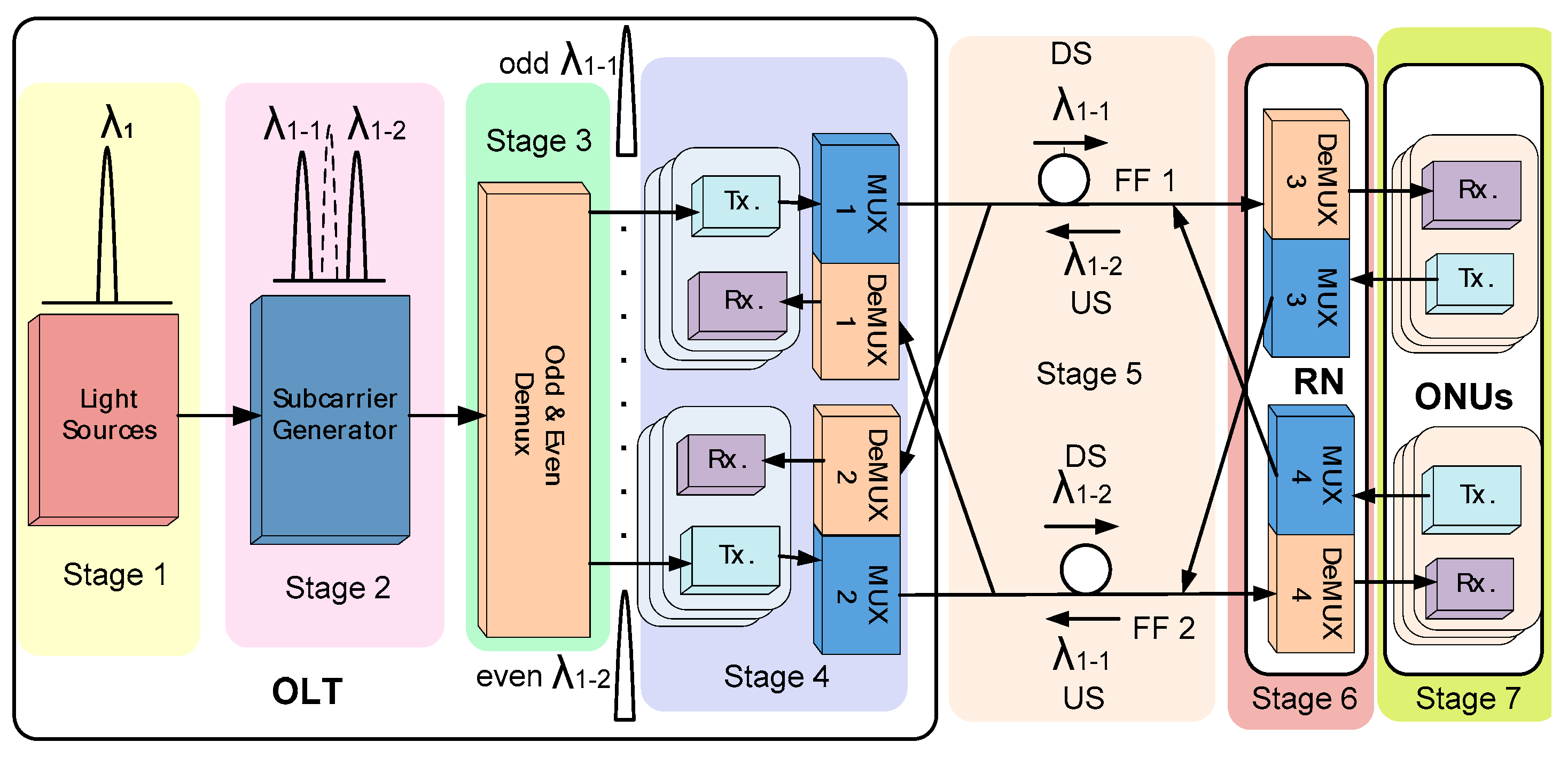
2. The System’s Design, Architecture, and Operating Principles

The basic system structure, operating description, and design enhancements for this work are presented in this section. The proposed high capacity DWDM-PON system, based on modified cross-seeding architecture, is shown in Figure 1. The Optical Line Terminal (OLT) can be divided into four stages, as illustrated in Figure 1. (A) Stage 1 represents the input light source, which consists of eight CW light sources that have a wavelength spacing of 25 GHz and combine together to be forced into Stage 2. (B) At Stage 2, the optical light sources are utilized to generate subcarriers by using the Double Sideband Optical Carrier Suppression (DSB-OCS) technique. In this work, the DSB-OCS technique is used to increase the system capacity to a record of 8 light sources with 16 subcarriers (i.e., channels) by decreasing the channel spacing to 12.5 GHz. Generally, DSB-OCS has high receiver sensitivity with a small power penalty [24,25]. At this stage, an Erbium-Doped Fiber Amplifier (EDFA) is used. Each sideband (i.e., subcarrier) acts as a Centralized Light Source (CLS) to be re-modulated for US subcarriers, as shown in Figure 1. (C) The subcarriers are demultiplexed as odd and even subcarriers to ready them for transmission through the two-bidirectional fibers, feed fiber 1 (FF1) and feed fiber 2 (FF2). This part of the operation takes place in Stage 3. In this work, this function is performed with much lower complexity compared to the related studies that utilized the cross-seeding technique [22,26,27], but without affecting the performance, as performance will be described later in Section 4. (D) Then, each odd and even subcarrier is modulated by on-off key (OOK) modulation at Stage 4. OOK is the simplest modulation format and relatively inexpensive. Thus, OOK is used to meet the ONU requirements, as mentioned before. The transmitter (Tx) in Figure 2 consists of a Continuous Wave (CW) laser source with a wavelength of (193.025 THz) and an output power of 0 dBm. It is externally modulated at 10 Gb/s with a Non-Return-to-Zero (NRZ) pseudorandom binary sequence in a Mach–Zehnder Modulator (MZM) with a 30 dB extinction ratio. The NRZ format has been widely implemented, mainly due to its signal bandwidth and its relatively easy generation [28]. In addition, stage 4 contains a receiver (Rx) for the US signal, as shown in Figure 2. A p–i–n photodiode/ photodetector (PIN) is used with Low-Pass Filter (LPF) to demodulate the US signal. The PIN specifications are 10 nA dark current and 1 A/W responsivity. The same Tx and Rx will be used again in Stage 7. The odd DS signals are multiplexed to be transmitted through FF1. Similarly, even DS signals are multiplexed to be transmitted through FF2.
Stage 5 represents the heart of the cross-seeding technique that eliminates RB. This is done by transmitting the odd DS signals after re-modulation (i.e., Stages 6, 7) as the US through FF2, as indicated in Figure 1. The same procedure will be applied to even DS signals but by passing them through FF1 after re-modulation. Recall that transmission via conventional full-duplex bidirectional techniques suffers from a huge level of RB [28,29], which forces researchers to find solutions, as indicated in Section 1.
Finally, in Stage 6, the RN consists of two multiplexers (MUX) and two demultiplexers (DeMUX). MUX and DeMUX are simpler and lower in cost than Array Waveguide Grating (AWG), which is a complex component consisting of a coupler and fiber grating [30]. Txs and Rxs are used for the demodulation/re-modulation in Stage 7 after the received signal is split by a 20:80 coupler. Only 20% of the signal power is used to extract the DS information by using the same receiver structure mentioned in Stage 4. The remaining 80% of the signal power is used for the re-modulation of the US by OOK, and its structure is mentioned in Stage 4. Using the Saving Array Waveguide Grating (AWG), an internal feed fiber, and RSOA is a merit of this work’s design compared to related studies that utilized cross-seeding techniques [22,26,27].

3. Extended System Architecture and Parameters

The proposed cross-seeding based DWDM-PON system is presented in details in Figure 2. The general stages, which are presented in Figure 1, are re-introduced with details in Figure 2.
It is noteworthy to mention that the main system’s stage specifications and their corresponding values are mentioned in the body of Section 2 and Table 1. In the following, the remaining commercial components’ specifications will be addressed. The first launched wavelength is located at 193.025 THz with 0 dB launched power using a CW light source. By utilizing other seven CW light sources and the DSB-OCS technique, the system capacity is enlarged to 16 subcarriers (i.e., channels) by decreasing the channel spacing to 12.5 GHz. A 6.25 GHz sine generator that feeds a standard MZM with a 30 dB extinction ratio and an EDFA that has a 20 dB gain and a 4 dB noise figure are used in stage 2.
In stage 3, a DeMUX with 10 GHz 3dB bandwidth and 0 dB insertion loss is utilized. Here, channels that reached the Tx in stage 4 achieve DS modulation via an externally modulated 10 Gb/s Non-Return-to-Zero (NRZ) pseudorandom binary sequence using the previous MZM specifications. As said before, the Rx in stage 4 will be used for demodulating the returned US signal with PIN and an LPF. The PIN specifications are 10 nA dark current and 1 A/W responsivity. A 4th order LPF with 0 dB insertion loss, 100 dB depth, and a cut off frequency of 1.875 GHz is used. As said before, the same Tx and Rx will be used again in Stage 7, which will provide simplicity and harmony to the proposed design. The MUX/DeMUX used in stage 4 and 6 for the US and DS channel selections have 10 GHz 3 dB bandwidth, 0 dB insertion loss, and 100 dB depth. The specifications of the bidirectional fibers used in Stage 5 are listed in Table 1.
Points (a–g), indicated in Figure 2, are used to trace, test, and evaluate the proposed design, as will be provided in Section 4.

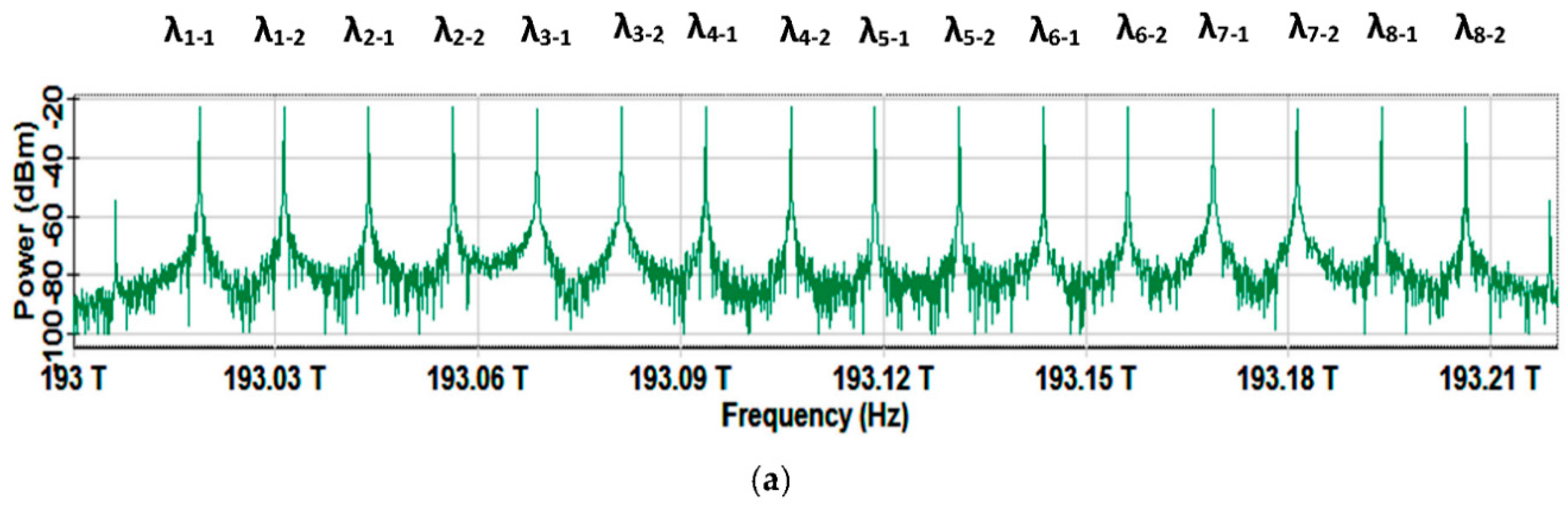
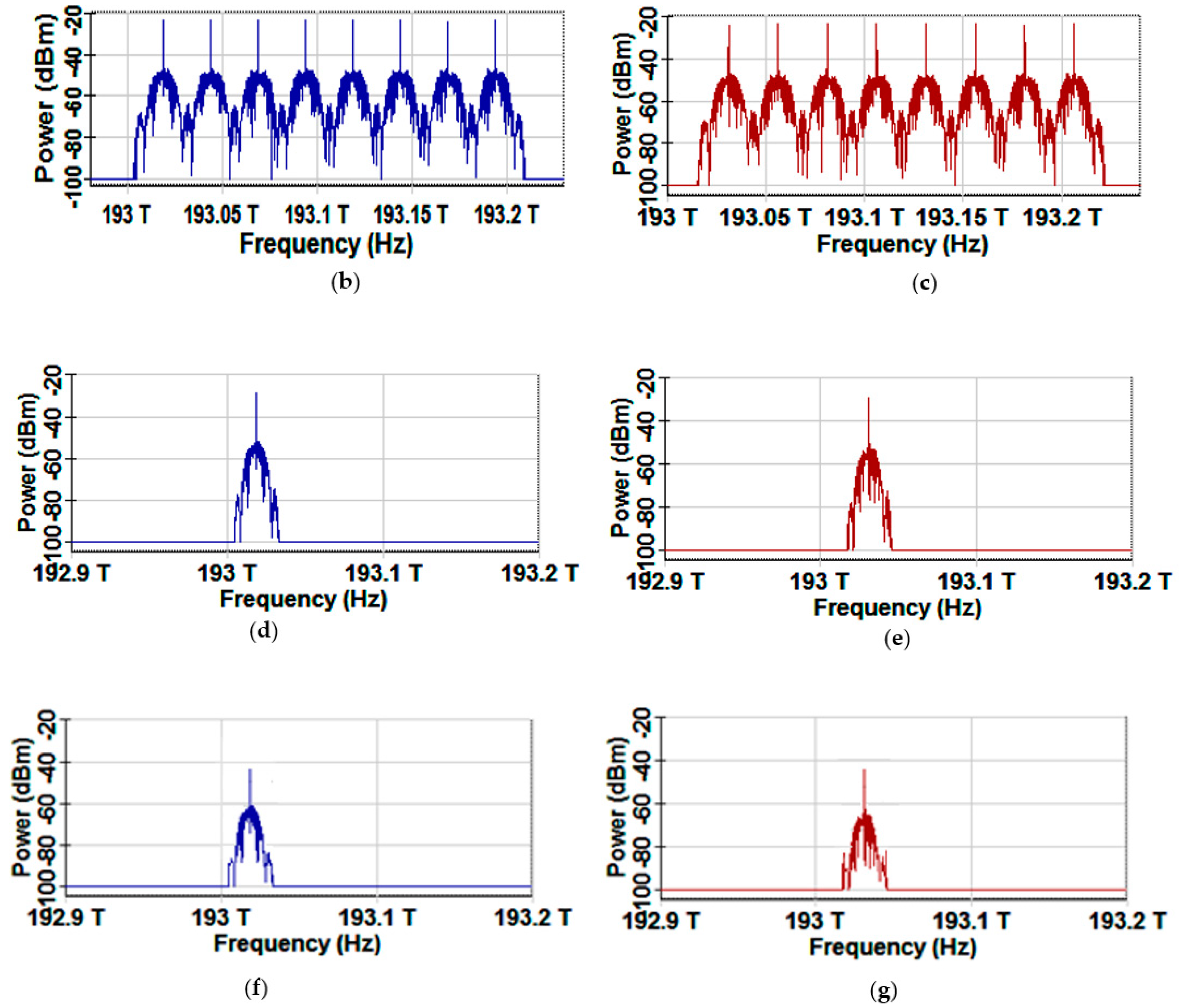
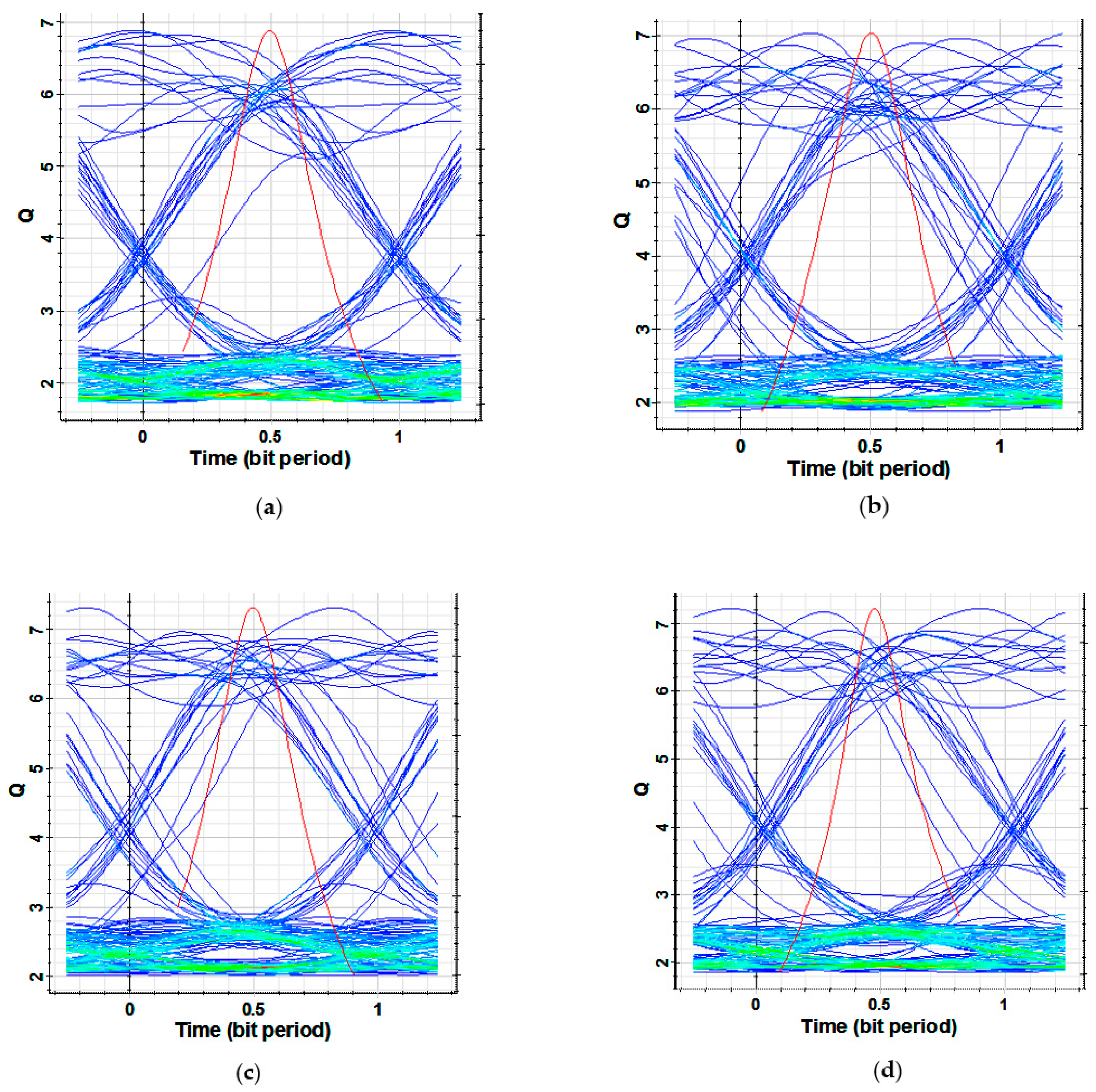
4. Results and Discussion

To verify this work’s goals, system tracing and evaluation are presented in this section. Figure 3a–g represents the optical spectra for signals processed through the proposed cross-seeding system, as indicated in Figure 2.
Figure 3a represents 16 DS channels with a channel spacing of 12.5 GHz starting from (λ1-1 = 193.019 THz) to (λ8-2 = 193.206 THz). These channels resulted from the eight CW light sources, each with 0 dB, after being forced to the MZM with a 6.25 GHz sine wave generator, as indicated in point (a) (Figure 2) and Table 1.
After being demultiplexed, the even and odd DS channels are modulated through IM with the NRZ format, each with 10 Gb/s. Finally, these channels are applied to DS MUX to provide the cross-seeding odd and even spectra ready to be transmitted through FF1 and FF2, respectively. These spectra are presented in Figure 3b,c and are considered to correspond to the system signals’ trace at points (b) and (c) in Figure 2.
Figure 3d represents the spectrum of a chosen odd DS channel spectrum (i.e., λ1-1 = 193.019 THz as an example for the odd channels) after transmitting 25 km through FF1 and after being demultiplexed at point (d) in Figure 2 before an ONU receiver. Figure 3f represents this channel after transmitting back through the retransmitting path (US path) with a record of 2.5 Gb/s (i.e., point (e) in Figure 2). One needs to remember (as in Figure 2) that the retransmitting path (US path) includes a CLS module, MUX, transmitting through FF2 (not in FF1, which is used in the DS path and is the core of the cross-seeding technique that eliminates RB), and, finally, DeMUX to reach a point (e) Figure 2.
A similar analysis is done by choosing the even DS channel λ1-2 = 193.031 THz as an example for the even channels. Figure 3e,g shows this channel spectrum after transmitting the DS path through FF2 and then returning using US path through FF1. These spectra correspond to the system trace at points (f) and (g) in Figure 2.
Finally, Figure 4 represents the eye diagrams for the selected odd and even channels after the retransmitting path (i.e., points (e) and (g) in Figure 2). Figure 4a,b represents the eye diagram evaluation for the previously chosen odd and even channels that are presented in Figure 3f,g (i.e., λ1-1 and λ1-2) while Figure 4c,d represents the eye diagram representation for the extra chosen channels (i.e., λ8-1 and λ8-2).
The results indicate that the worst simulated BER in the chosen samples can be observed for channel λ1-1 of 10−12, which corresponds to a quality factor (Q) of 6.88, while a remarkable simulated BER of 10−13, which corresponds to a quality factor (Q) of 7.03, is noticed for channel λ1-2. An average BER better than 10−12 can be observed for the remaining channels.
To provide a deeper understanding of Figure 4, it is useful to review some of the eye diagram basics and characteristics. The red curve in Figure 4 represents the ideal received bit pattern only, while the blue pattern represents a normalized pattern for the 2 bits actually received, with the 1 bit “eye-opening” in the center of the display and 1/2 bit to the left and right of the center eye to capture the rise/fall-time transitions [31,32,33].
The eye diagram is a useful tool for the qualitative analysis of the signals used in digital transmission. This diagram provides an at-a-glance evaluation of the system performance and can offer insight into the nature of the channel’s imperfections. Careful analysis of this visual display can give the user a first-order approximation of the signal-to-noise ratio, clock timing jitter, and skew [31,32,33].
Several key values can be extracted directly from Figure 4, such as the One Level, Zero Level, Eye Amplitude, eye height, crossing point, rise time, and fall time. Then, system performance indicators, such as the Eye Crossing Percentage, signal to noise ratio, eye width, Duty Cycle Distortion, BER, and quality factor, can be directly calculated using simple and direct relations based on the key values [31]. Finally, it is worth mentioning that today’s manufacturers provide devices that directly display all previous values and system indicators once the system is tested [31,32].

5. Comparison with Related Studies

This section provides a detailed specification comparison between this work and related literature. It is worth mentioning that the key differences between this work’s technique (cross-seeding) and other techniques related to the critical requirements for the DWDM-PON system are already discussed in Section 1. In addition, the reasons, which have motivated us to use the cross-seeding technique, are also discussed there.
Table 2 represents a detailed specification and value comparison between this work and related studies. Again, as mentioned in Section 1, the comparison includes literature not only for DWDM-PON systems and WDM-PON, but also for Hybrid WDM/TDM-PON and other related systems.
For example, in [5], the number of channels, US, and DS rates are remarkable, but the problems associated with the use of (FP-L) (mentioned in Section 1) limit the transmission distance, the ability to use more channels (i.e., channel spacing), and the BER. Besides the FP-L influence, this work utilizes a higher Dispersion Compensation Fiber (DCF) length of −340 ps/nm to provide the aforementioned performance characteristics in Table 2 for 15 km. The effect of, and price of, the high length DCF can be found in many dispersion compensation-related studies, such as [35,36]. Finally, an in-band cross talk, which cannot be avoided, is observed through the system’s testing [5].
Another nominated example can be reviewed in [21]. The effect of using high gain ROSA limits the US/DS bitrates, the ability to use more channels (i.e., channel spacing), and the BER. To enhance the merged TDM capacity, a high data rate optical source may be used [37]. Finally, the BER enhances to 10−9 if the number of channels is reduced to only one (as in this work) [21].
A Long-Reach Bidirectional Centralized WDM-PON system, with attractive operating characteristics, is achieved in [19]. The use of centralized light sources is a desirable solution to reduce system monitoring and maintenance cost [19,38]. However, the utilization of OCS-SCM with its advantages and disadvantages (as in Section 1) limits the number of channels due to the large channel spacing required. A review of this system’s architecture leads to a moderate-to-high level of complexity. This complexity is due to the existence of two EDFAs—AWG and long DCF [19].
Dual-arm modulator configurations are proposed in [20] to perform wavelength shifting for the ONUs to mitigate the RB impairment in bidirectional centralized light PONs. Although the proposed configurations reduce the dependence of the system on devices like EDFAs, AWG, and long DCF, the use of a combination of amplitude and phase modulation dramatically limits the US and DS rates [20]. On the other hand, this work, with its low operating rate, can provide perfect integration between a WDM-PON system (as a step toward 5G systems) and other low bit rate commercial 5G systems, such as the single carrier modulation (SCM) visible light communication (VLC) systems, as well as their applications [39,40]. The limited number of channels and the non-availability of such a modulator at that time are additional limitations [20].
The highest observed US and DS rates are accomplished with a record of 40 Gb/s in [10]. This work utilizes an integrated semiconductor optical amplifier with a reflective electro-absorption modulator (SOA-REAM). The idea of integrating everything into one compact device is currently pioneering and seems promising. Unfortunately, severe inter-symbol interference and strong beat noise are major limitations [10]. A material like a linear/non-linear photonic crystal (Phc) could mitigate these limitations. With its remarkable integration ability, low power consumption, and remarkable performance in variety of applications [41,42,43], the functionality of SOA-REAM can be achieved with attractive operational characteristics. In [10], several techniques are proposed to overcome these limitations, but the effects of these limitations dominate, since the optimum allowable BER = 2 × 10⁻⁴, with 20 Km and one channel.

6. Conclusions

This work simulates an enhanced cross-seeding-based DWDM-PON system with future channel spacing in the ITU-T G.694.1 standard for DWDM (i.e., 12.5 GHz). Attractive performance characteristics have been targeted through this work. These characteristics include enhancing the downstream (DS) channel capacity, the US bit rate, minimizing the active components, and maintaining the remarkable BER performance. Utilizing this work’s design enhancement, the proposed DWDM-PON has successfully achieved a record of 16 channels, a US capacity of 2.5 Gb/s over 25 km of transmission, and a noteworthy average BER of 10−12. A comparison between this work and related studies, which are not only based on DWDM-PON systems but also cover other types of high-speed optical networks, was performed to ensure the validity and effectiveness of the proposed system.

Author Contributions

Conceptualization, N.A.M.; Methodology, N.A.M.; Software, N.A.M.; Formal analysis, N.A.M.; Writing—original draft preparation, N.A.M.; Writing—review and editing, A.H.M.; Supervision, A.H.M.; Resources, A.H.M.

Funding

This research received no external funding.

Conflicts of Interest

The authors declare no conflict of interest.

References

  1. Bindhaiq, S.; Supaat, A.S.M.; Zulkifli, N.; Mohammad, A.B.; Shaddad, R.Q.; Elmagzoub, M.A.; Faisal, A. Recent development on time and wavelength-division multiplexed passive optical network (TWDM-PON) for next-generation passive optical network stage 2 (NG-PON2). Opt. Switch. Netw. 2015, 15, 53–66. [Google Scholar] [CrossRef]
  2. Kaminow, I.; Li, T.Y.; Willner, A. Optical Fiber Telecommunications VIB Systems and Networks, 6th ed.; Elsevier: Waltham, MA, USA, 2013; pp. 928–929. [Google Scholar]
  3. Cheng, M.C.; Tsai, C.T.; Chi, Y.C.; Lin, G.R. Direct QAM-OFDM Encoding of an L-band Master-to-Slave Injection-Locked WRC-FPLD Pair for 28 × 20 Gb/s DWDM-PON Transmission. J. Lightwave Technol. 2014, 32, 2981–2988. [Google Scholar] [CrossRef]
  4. Chen, J.; Wosinska, L.; He, S. High Utilization of Wavelengths and Simple Interconnection Between Users in a Protection Scheme for Passive Optical Networks. IEEE Photonics Technol. Lett. 2008, 20, 389–391. [Google Scholar] [CrossRef]
  5. Xu, Z.; Wen, Y.J.; Zhong, W.D.; Chae, C.J.; Cheng, X.F.; Wang, Y.; Lu, C.; Shankar, J. High-speed WDM-PON using CW injection-locked Fabry-Pérot laser diodes. Opt. Express 2007, 15, 2953–2962. [Google Scholar] [CrossRef]
  6. Lin, S.Y.; Chi, Y.C.; Su, Y.C.; Liao, J.W.; Wang, H.L.; Lin, G.C.; Lin, G.R. Coherent Injection-Locking of Long-Cavity Colorless Laser Diodes with Low Front-Facet Reflectance for DWDM-PON Transmission. IEEE J. Sel. Top. Quantum Electron. 2013, 19, 1501011. [Google Scholar]
  7. Lin, S.C.; Lee, S.L.; Liu, C.K. Simple approach for bidirectional performance enhancement on WDM-PONs with direct-modulation lasers and RSOAs. Opt. Express 2008, 16, 3636–3643. [Google Scholar] [CrossRef]
  8. Naughton, A.; Talli, G.; Porto, S.; Antony, C.; Ossieur, P.; Townsend, P.D. Design Optimization of R-EAM-SOA for Long-Reach Carrier-Distributed Passive Optical Networks. J. Lightwave Technol. 2014, 32, 4386–4392. [Google Scholar] [CrossRef]
  9. Al-Qazwini, Z.; Kim, H. Symmetric 10-Gb/s WDM-PON Using Directly Modulated Lasers for Downlink and RSOAs for Uplink. J. Lightwave Technol. 2012, 30, 1891–1899. [Google Scholar] [CrossRef]
  10. Guo, Q.; Tran, A.V. 40 Gb/s Operation of SOA-REAM in Single-Feeder WDM-PON [Invited]. J. Opt. Commun. Netw. 2012, 4, 77–84. [Google Scholar] [CrossRef]
  11. Chow, C.W.; Yeh, C.H.; Wu, Y.F.; Lin, Y.H.; Shih, F.Y.; Chi, S. Rayleigh Backscattering Circumvention in Ring-Based Access Network Using RSOA-ONU. IEEE Photonics Technol. Lett. 2011, 23, 1121–1123. [Google Scholar] [CrossRef]
  12. Senior, J.M. Optical Fiber Communications Principles and Practice, 3rd ed.; Pearson Education: London, UK, 2009; pp. 95–97. [Google Scholar]
  13. Nakazawa, M. Rayleigh backscattering theory for single-mode optical fibers. J. Opt. Soc. Am. 1983, 73, 1175–1180. [Google Scholar] [CrossRef]
  14. Liaw, S.K.; Tzeng, S.L.; Hung, Y.J. Rayleigh backscattering induced power penalty on bidirectional wavelength-reuse fiber systems. Opt. Commun. 2001, 188, 63–67. [Google Scholar] [CrossRef]
  15. Staubli, R.K.; Gysel, P. Crosstalk penalities due to coherent Rayleigh noise in bidirectional optical communication systems. J. Lightwave Technol. 1991, 9, 375–380. [Google Scholar] [CrossRef]
  16. Xu, M.; Chi, Y.C.; Wang, J.; Cheng, L.; Lu, F.; Khalil, M.I.; Tsai, C.T.; Lin, G.R.; Chang, G.K. Wavelength sharing and reuse in dual-band WDM-PON systems employing WRC-FPLDs. IEEE Photonics Technol. Lett. 2015, 27, 1821–1824. [Google Scholar] [CrossRef]
  17. Simatupang, J.W.; Lee, S.L. Transfer matrix analysis of backscattering and reflection effects on WDM-PON systems. Opt. Express 2013, 21, 27565–27577. [Google Scholar] [CrossRef]
  18. Chow, C.W.; Yeh, C.H. Using Downstream DPSK and Upstream Wavelength-Shifted ask for Rayleigh Backscattering Mitigation in TDM-PON to WDM-PON Migration Scheme. IEEE Photonics J. 2013, 5, 7900407. [Google Scholar] [CrossRef]
  19. Chowdhury, A.; Chien, H.C.; Huang, M.F.; Yu, J.; Chang, G.K. Rayleigh Backscattering Noise-Eliminated 115-km Long-Reach Bidirectional Centralized WDM-PON with 10-Gb/s DPSK Downstream and Remodulated 2.5-Gb/s OCS-SCM Upstream Signal. IEEE Photonics Technol. Lett. 2008, 20, 2081–2083. [Google Scholar] [CrossRef]
  20. Omella, M.; Lazaro, J.; Polo, V.; Prat, J. Driving Requirements for Wavelength Shifting in Colorless ONU With Dual-Arm Modulator. J. Lightwave Technol. 2009, 27, 3912–3918. [Google Scholar] [CrossRef]
  21. De Valicourt, G.; Make, D.; Landreau, J.; Lamponi, M.; Duan, G.; Chanclou, P.; Brenot, R. High Gain (30 dB) and High Saturation Power (11 dBm) RSOA Devices as Colorless ONU Sources in Long-Reach Hybrid WDM/TDM-PON Architecture. IEEE Photonics Technol. Lett. 2010, 22, 191–193. [Google Scholar] [CrossRef]
  22. Zhou, Z.; Xiao, S.; Qi, T.; Li, P.; Bi, M.; Hu, W. 25-GHz-Spaced DWDM-PON with Mitigated Rayleigh Backscattering and Back-Reflection Effects. IEEE Photonics J. 2013, 5, 7901407. [Google Scholar] [CrossRef]
  23. Lin, S.C.; Lee, S.L.; Lin, H.H.; Keiser, G.; Ram, R.J. Cross-Seeding Schemes for WDM-Based Next-Generation Optical Access Networks. J. Lightwave Technol. 2011, 29, 3727–3736. [Google Scholar] [CrossRef]
  24. Huang, Q.; Peng, P.C.; Fu, S.F.; Yang, W.Y.; Huang, J.H.; Yee, H.H. Double Sideband with Optical Carrier Suppression Scheme for Broadcasting Transmission. IEEE Photonics Technol. Lett. 2014, 26, 1172–1175. [Google Scholar]
  25. Yeh, C.H.; Chow, C.W.; Chen, H.Y. Simple Colorless WDM-PON with Rayleigh Backscattering Noise Circumvention Employing m-QAM OFDM Downstream and Remodulated OOK Upstream Signals. J. Lightwave Technol. 2012, 30, 2151–2155. [Google Scholar] [CrossRef]
  26. Chiuchiarelli, A.; Proietti, R.; Presi, M.; Choudhury, P.; Contestabile, G.; Ciaramella, E. Symmetric 10 Gbit/s WDM-PON based on cross-wavelength reuse to avoid Rayleigh backscattering and maximise band usage. Electron. Lett. 2009, 45, 1343. [Google Scholar] [CrossRef]
  27. Agalliu, R.; Lucki, M. Benefits and Limits of Modulation Formats for Optical Communications. Adv. Electr. Electron. Eng. 2014, 12, 160–167. [Google Scholar] [CrossRef]
  28. Feng, Q.G.; Li, W.; Zheng, Q.; Han, J.L.; Xiao, J.X.; He, Z.X.; Luo, M.; Yang, Q.; Yu, S.H. Impacts of backscattering noises on upstream signals in full-duplex bidirectional PONs. Opt. Express 2015, 23, 15575–15586. [Google Scholar] [CrossRef]
  29. Xu, J.; Li, M.; Chen, L.K. Rayleigh Noise Reduction in 10-Gb/s Carrier-Distributed WDM-PONs Using In-Band Optical Filtering. J. Lightwave Technol. 2011, 29, 3632–3639. [Google Scholar]
  30. Lin, C.F. Optical Components for Communications: Principles and Applications, 1st ed.; Springer Science & Business Media: New York, NY, USA, 2004; pp. 277–292. [Google Scholar]
  31. Anritsu Corporation. Available online: https://rintintin.colorado.edu/~gifford/5830-AWL/Anritsu%20Eye%20Diagram.pdf (accessed on 15 July 2019).
  32. Breed, G. Analyzing signals using the eye diagram. High Freq. Electron. 2005, 4, 50–53. [Google Scholar]
  33. Senior, J.M. Optical Fiber Communications Principles and Practice, 3rd ed.; Pearson Education: London, UK, 2009; pp. 708–713. [Google Scholar]
  34. Simatupang, J.W.; Pukhrambam, P.D.; Huang, Y.R. Performance analysis of cross-seeding WDM-PON system using transfer matrix method. Opt. Fiber Technol. 2016, 32, 50–57. [Google Scholar] [CrossRef]
  35. Mohammed, N.A.; Solaiman, M.; Aly, M.H. Design and performance evaluation of a dispersion compensation unit using several chirping functions in a tanh apodized FBG and comparison with dispersion compensation fiber. Appl. Opt. 2014, 53, 239–247. [Google Scholar] [CrossRef]
  36. Mohammed, N.A.; Okasha, N.M. Single-and dual-band dispersion compensation unit using apodized chirped fiber Bragg grating. J. Comput. Electron. 2018, 17, 349–360. [Google Scholar] [CrossRef]
  37. Mohammed, N.A.; Elkhamisy, K.M.; Aly, M.H. Pedestal Free Pulse Source for Ultrahigh Data Rate Optical Time Division Multiplexing Systems Self-Phase Modulation Based. J. Nanoelectron. Optoelectron. 2017, 12, 505–511. [Google Scholar] [CrossRef] [Green Version]
  38. Elewah, I.A.; Mohammed, N.A.; Aly, M.H. 20-Gb/s Transmission Over 25-km in Wavelength Division Multiplexing Passive Optical Network with Centralized Light Source. J. Nanoelectron. Optoelectron. 2017, 12, 242–246. [Google Scholar] [CrossRef]
  39. Mohammed, N.A.; Badawi, K.A. Design and Performance Evaluation for a Non-Line of Sight VLC Dimmable System Based on SC-LPPM. IEEE Access 2018, 6, 52393–52405. [Google Scholar] [CrossRef]
  40. Mohammed, N.A.; Elkarim, M.A. Exploring the effect of diffuse reflection on indoor localization systems based on RSSI-VLC. Opt. Express 2015, 23, 20297–20313. [Google Scholar] [CrossRef]
  41. Mostafa, T.S.; Mohammed, N.A.; El-Rabaie, E.S.M. Ultracompact ultrafast-switching-speed all-optical 4 × 2 encoder based on photonic crystal. J. Comput. Electron. 2019, 18, 279–292. [Google Scholar] [CrossRef]
  42. Mostafa, T.S.; Mohammed, N.A.; El-Rabaie, E.S.M. Ultra-High bit rate all-optical AND/OR logic gates based on photonic crystal with multi-wavelength simultaneous operation. J. Mod. Opt. 2019, 66, 1005–1016. [Google Scholar] [CrossRef]
  43. Mohammed, N.A.; Hamed, M.M.; Khalaf, A.A.; Alsayyari, A.; EL-Rabaie, S. High-sensitivity ultra-quality factor and remarkable compact blood components biomedical sensor based on nanocavity coupled photonic crystal. Results Phys. 2019, 14, 102478. [Google Scholar] [CrossRef]
Figure 1. The proposed high capacity Dense Wavelength Division Multiplexing (DWDM-PON) system based on the modified cross seeding architecture; DeMUX: demultiplexer; Tx.: transmitter; Rx.: receiver; MUX: multiplexer; DS: downstream path; US: upstream path; FF1: feed fiber 1; FF2: feed fiber 2; RN: remote node; ONUs: optical network units.
Applsci 09 04520 g001
Figure 2. Detailed design for the proposed DWDM-PON system with enhanced cross seeding mechanism. MZM: Mach Zehnder modulator; EDFA: Erbium-Doped Fiber Amplifier; NRZ: Non-Return to Zero; IM: Intensity Modulator; LPF: Low Pass Filter.
Applsci 09 04520 g002
Figure 3. System trace and evaluation (a); 16 DS channels with channel spacing 12.5 GHz; (b) eight DS odd channels before transmitting through feed fiber 1 (FF1); (c) eight DS even channels before transmitting through FF2; (d) the DS odd channel λ1-1 before the optical network unit (ONU) (e); the DS even λ1-2 channel before the ONU (f); the US odd channel λ1-1 after the US path (g); the US even channel λ1-2 after the US path.
Applsci 09 04520 g003aApplsci 09 04520 g003b
Figure 4. Eye diagrams for odd and even channels after the retransmitting path (a) λ1-1, (b) λ1-2, (c) λ8-1, and (d) λ8-2.
Applsci 09 04520 g004
Table 1. The main parameters for the proposed DWDM-PON system components.
ComponentParameterValue(s)Unit
CW LaserFirst Wavelength193.025THz
Wavelength spacing25GHz
Launching power0dB
Sine GeneratorFrequency6.25GHz
OLT TransmitterDS Bit rate10Gb/s
Bidirectional optical fiberLength25Km
Attenuation0.2dB/Km
ONU TransmitterUS Bit rate2.5Gb/s
Table 2. A comparison between the studies and the presented work for different optical network systems.
RefSystemNo. of ChannelsMaximum 1 Length KmMinimum 2 Channel Spacing GHzMaximum 1 US Bit Rate Gb/sMaximum 1 DS Bit Rate Gb/sOptimum BER
[5]WDM-PON1615140101010−9
[6]DWDM-PON3252002.52.510−9
[7]DRWDM-PON 32251001.251010−9
[8]Class C GPON 41NA 101010−10
[9]WDM-PON420NA101010−4
[10]WDM-PON120 404010−4
[11]WDM-TDM220502.51010−9
[18]Migration scheme from TDM-PON to WDM-PON120 1010<10−9 for DS 10−3 for US
[19]Long-Reach Bidirectional Centralized WDM-PON1115 2.51010−10
[20]WDM-PON With Wavelength Shifting in Colorless ONU125 1.252.5010−9
[21]Hybrid WDM/TDM-PON8451002.52.510−7
[22]DWDM-PON625251.251010−9
[23]WDM-PON2251001.251010−10
[34]WDM-PONNA25NANANA10−9
This workDWDM-PON162512.52.5 1010−12
1 The maximum value achieved through several experiments and simulation trials. 2 The minimum value achieved through several experiments and simulation trials. 3 DRWDM-PON are WDM-PONs that employ directly modulated lasers (DMLs) at the CO and RSOAs at the ONUs. 4 GPON = Gigabit passive optical network.

