Article

Microstructure and Tribological Properties of Self-Lubricating FeS Coating Prepared by Chemical Bath Deposition Coating Technique

1
College of Material Science and Engineering, Chongqing University of Technology, Chongqing 400054, China
2
Chongqing Municipal Key Laboratory of Institutions of Higher Education for Mould Technology, Chongqing University of Technology, Chongqing 400054, China
3
School of Materials and Energy, Southwest University, Chongqing 400715, China
*
Authors to whom correspondence should be addressed.
Appl. Sci. 2019, 9(20), 4422; https://doi.org/10.3390/app9204422
Submission received: 13 September 2019 / Revised: 6 October 2019 / Accepted: 16 October 2019 / Published: 18 October 2019
(This article belongs to the Special Issue Novel Insights into Tribological Coatings)

Abstract

:
The FeS solid lubricating coatings were prepared on the AISI 5140 steel by chemical bath deposition (CBD) coating technique at various temperatures from 30 to 90 °C. The influence of temperature on microstructure, microcracks, and tribological properties was characterized and studied by X-ray diffraction (XRD), scanning electron microscope (SEM), and energy dispersive spectrometry (EDS). The results show that the coating mainly consists of FexSy (FeS, FeS2, and Fe1−xS), and has a chrysanthemum-shaped (CS) morphology composed of the FeS crystal petals. The CS particles nucleate at about 30 °C, rapidly grow and reach a peak thickness at about 50–70 °C, and finally disappear and are replaced by disordered thick petals at 90 °C. The wear resistance of the steel was improved obviously after introducing of FeS coatings, owing to that the coatings can provide better lubrication and improve the wear resistance.

Graphical Abstract

1. Introduction

Gear transmission is one of the most important transmission methods in modern machinery because of its many attractive properties like high transmission efficiency, accurate and stable, high transmission power, and wide applicable speed range [1,2,3]. With the progress of technology and the development of gear transmission, the gear is developed toward high speed, heavy load, complex service environment, and high reliability [4]. The development of transmission systems has made gear materials to be upgraded in the direction of light weight, good wear resistance, good corrosion resistance, and economic efficiency [5].
The primary failure mode of gears is wear, which is a gradual loss of surface materials because of the friction between the two contact gears [5,6]. The friction on the gear surfaces greatly affects the power loss and service life of the transmission system [7]. Unfavorable working environment, such as poor lubricity, can lead to rapid failure of the gears, seriously undermining the reliability of the transmission system [8]. According to incomplete statistics, about 1/3~1/2 of primary energy is consumed by friction, and about 70% of equipment failures are related to the wear failure of gears [9]. Therefore, how to improve the gear service performance, reduce material loss and energy consumption, and avoid safety accident caused by friction and wear are of great significance.
Improving the wear resistance of gear materials mainly starts from two aspects: one is to improve the surface hardness of the gear material, and the other is to introduce a lubricating medium. For the first, surface strengthening methods such as carburizing [10,11], nitriding [12,13], carbonitriding [14,15], thermal chromizing [16,17,18], electron beam surface treatment [4,16], electro brush-plating [5], double glow plasma surface alloying [19,20], or deformation induced martensite [21] are commonly used to improve the performance of the steel surface. However, the hard surface accelerates the wear of its counterpart and is ineffective in preventing strain fatigue of the substrate, which results in scuffing failure, especially under boundary lubrication of rubbing-pairs [22]. Generally, the lubricity of the materials can be improved by introducing liquid or solid lubrication medium, designing shallow holes for storing lubricating oil on the surface of the material [23], introducing nanoparticles as lubricant additives [24], replacing metal–metal friction pairs by metal–polymer ones [25], surface texturing treatment [26,27,28], and surface geometry modification [29]. Depositing a solid lubricating coating on the gear surface is considered to be a simple and very effective approach to improve the wear resistance of materials. FeS is considered as an excellent solid lubricant because of its hexagonal structure, low shear strength, and high melting point [22,30,31,32,33,34]. Moreover, the cost is very low, only about 1% that of MoS2 coating which is also considered as a good solid lubricant for the gears [35,36]. Recently, it has been confirmed that the FeS solid lubrication coatings deposited on steels by ion sulfurizing [22,31,37,38,39], plasma spraying [22,40], plasma source ion sulfurizing [41], can significantly improve the lubrication property of steels. In this study, the FeS coatings were prepared on commercial AISI 5140 steel by a chemical bath deposition (CBD) coating technique at various temperatures. The influence of reaction temperature on the microstructure, microcracks, and lubrication properties were investigated.

2. Materials and Methods

Commercial AISI 5140 steel with a chemical composition of Fe-0.40C-0.23Si-0.7Mn-0.8Cr-0.03Ni (wt%) was selected as the substrate material. The steel was cut into samples with a gauge dimension of 25 × 15 × 3 mm3. A facile CBD method was carried out for preparing the FeS coatings on the steel. The CBD was originally used to prepare thin films or nanomaterials [42,43,44], and was recently used to deposit coatings [45]. The samples were sequentially ground, polished and ultrasonically cleaned, and finally immersed into a CBD solution bath. The solution formulation is as follows: 8.0 g Na2SO3, (≥97.0%), 2.5 g Na2S2O3·5H2O (≥99.0%), 3.0 g C4H4O6 (≥99.5%), 1.5 g FeSO4·7H2O (≥99.0%), and 100 mL de-ionized water.
In the bath, the steel substrate (anode) is oxidized and dissolved because of its low potential and the loss of electrons. The reaction formula is as follows:
Fe → Fe2+ + 2e−
For the cathode, the main chemical reaction is the decomposition reaction of S2O32−. The reaction formula is as follows:
S2032− + 2e → S032− + S2−
With the increase of S2− and Fe2+ in the metal surface accessories, the coating formation reaction occurs when [S2−] [Fe2+] [FeS]. The reaction formula is as follows:
Fe2+ + S2− → FeS
Finally, the FeS is deposited on the surface of the steel substrate. The CBD treatments were carried out for 1 h at 30, 40, 50, 70, and 90 °C (denoted as S30, S40, S50, etc., respectively). After the CBD treatment, the obtained black samples were rinsed with running water and ethyl alcohol to clean the residual solution. The samples were dried by air and then soaked in engine oil for 3 h at room temperature. Finally, the soaked samples were taken out and placed on the table for two days (atmospheric environment) to obtain an oil film on the sample surface, which brings the wear test conditions closer to the actual service environment.
A field emission scanning electron microscope (FE-SEM, Zeiss ΣIGMA HDTM, Oberkochen, Germany) equipped with secondary electron imaging (SEI) and energy dispersive spectrometry (EDS) was utilized to characterize the microstructure and element distribution of the treated samples. X-ray diffraction technique (XRD, PANalytical Empyrean Series 2, Almelo, Nederlands) was employed to determine the phase components of the coatings. The wear property was determined by a reciprocating tribometer (MS-T3001, Lanzhou Huahui Instrument Technology Co., Ltd., Lanzhou, China) with the 5 mm diameter steel balls (AISI 52100) as friction pairs. The steel ball slides linearly back and forth on the sample surface. The testing parameters were as follows: Load 6.0 N, duration time 10 min, frequency 2.0 Hz, wear scar length 10 mm. At least two sets of data were tested for each sample to verify the repeatability of the test results.

3. Results and Discussion

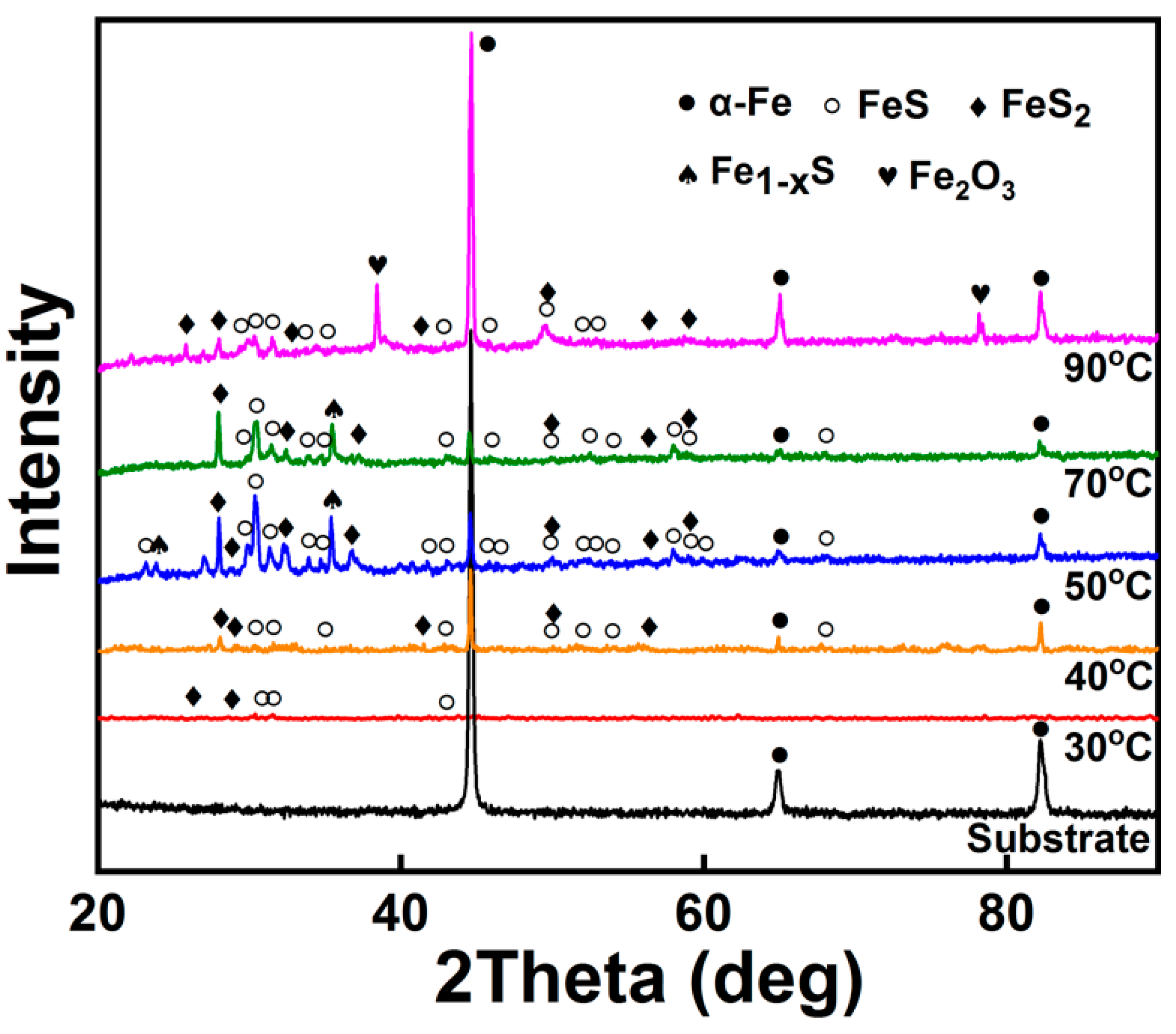
3.1. Phase Composition

Figure 1 shows the XRD patterns of the substrate and coatings prepared at various temperatures. Phases were identified from the XRD pattern using the International Center for Diffraction Data (ICDD) database. It should be noted that since the coating thickness of the samples is too thin, the grazing-incident X-ray and asymmetric-Bragg diffraction was employed to test the phases. As can be seen, the coating in the S30 sample consists mainly of FeS and FeS2. When the temperature rises to 50 °C, the FeS intensity reaches a maximum and a new Fe1−xS phase is produced. It is because that in the range of 50 to 70 °C, the evaporation of water in the chemical solution is accelerated, and the increase in the concentration of the solution causes the intensity of FexSy (FeS, FeS2, and Fe1−xS) to rapidly increase. As the temperature increases to 90 °C, the density of FexSy decreases significantly. This is because that the moisture in the chemical solution evaporates sharply at high temperature and a large amount of solute precipitates to lower the concentration of the solution, resulting in a decrease in the reaction product of FexSy. Moreover, Fe2O3 is identified in the S90 sample, indicating that the substrate has been oxidized at this temperature. From the XRD results, it can be concluded that the optimum chemical solution temperature is between 50 and 70 °C, since the coatings mainly consist of FexSy (FeS FeS2, and Fe1−xS).

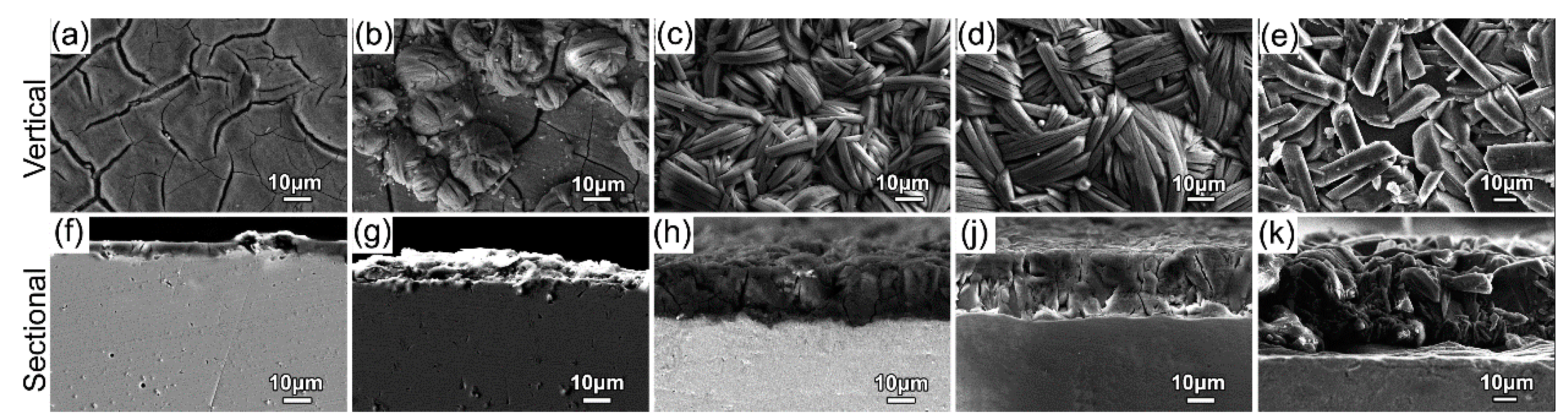
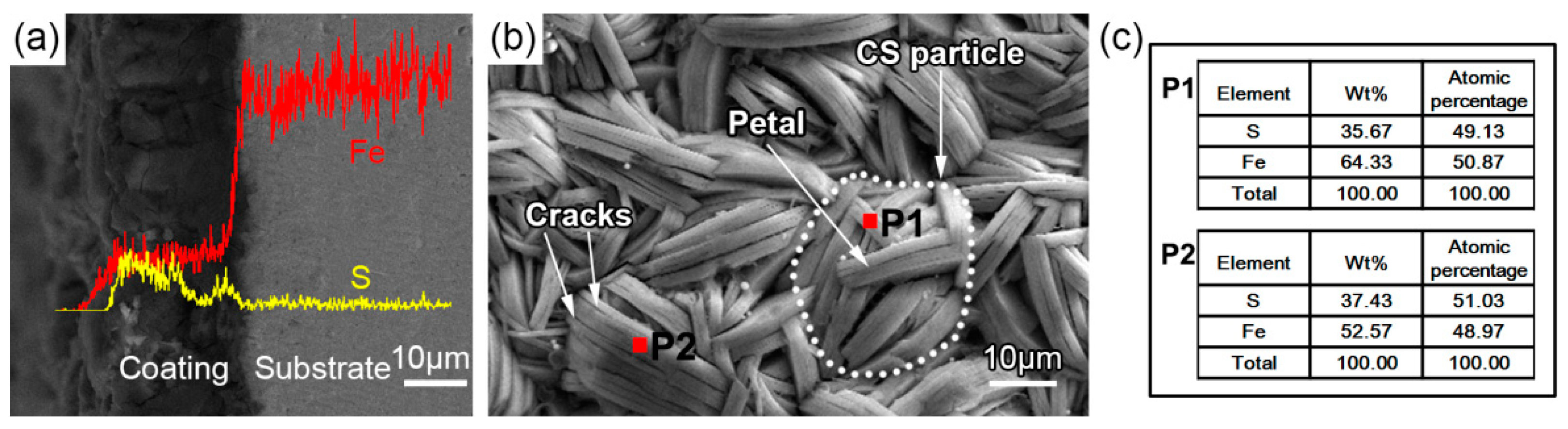
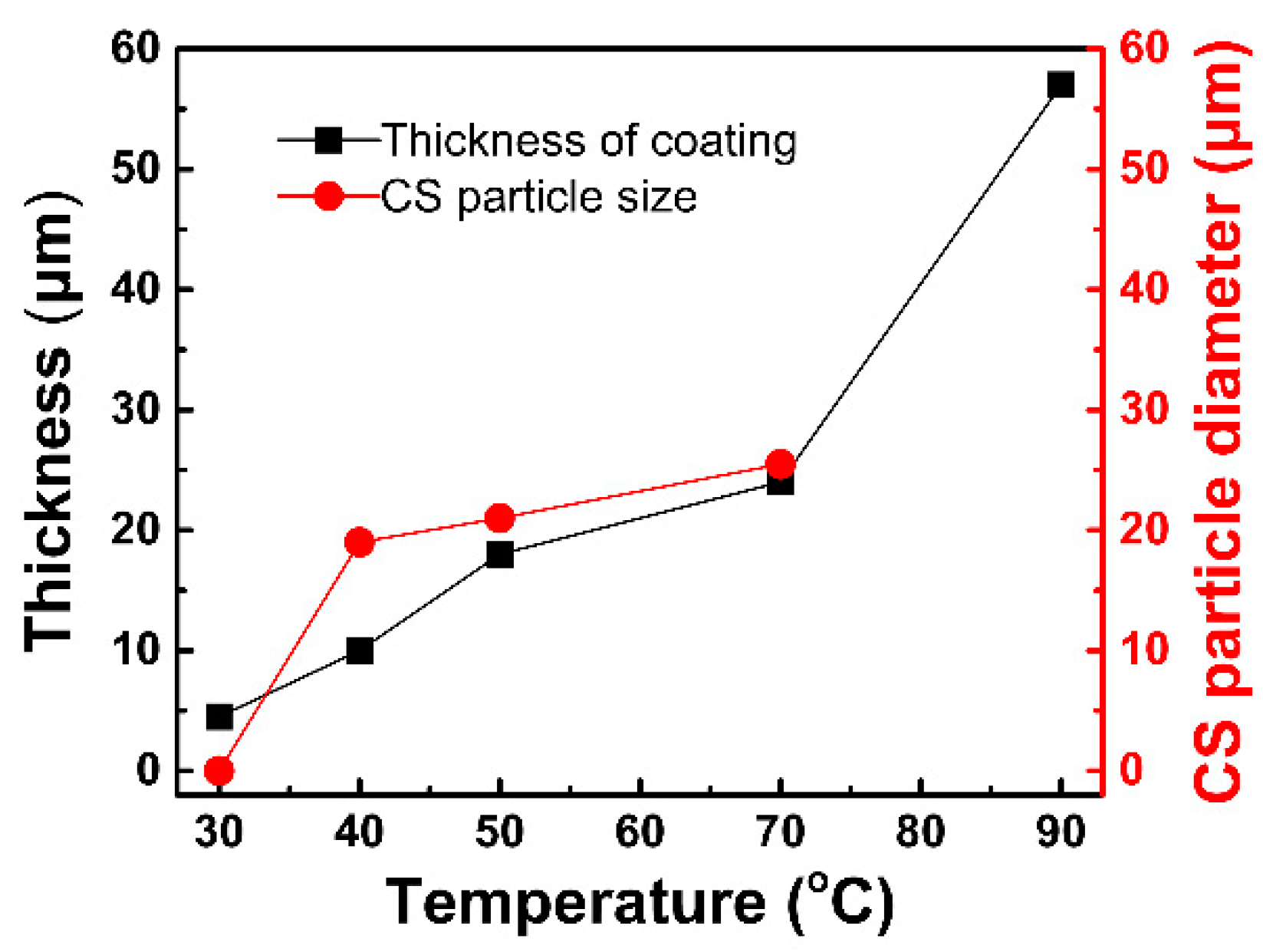
3.2. Microstructure Evolution

Figure 2 presents the SEI images from the vertical and cross-sectional views of the samples prepared at various temperatures. Figure 2a shows the microstructure of the S30 sample. It can be seen that when the reaction temperature is 30 °C, the coating thickness is very thin (about 4 μm, see Figure 2f), the surface morphology of the coating is similar to the dry riverbed covered with network-like cracks (see Figure 2a), and the crystalline products do not cover the entire surface. When the temperature is increased to 40 °C, no significant increase in coating thickness is observed (see Figure 2g), but a large amount of crystalline product having a chrysanthemum shape is found on the surface of the coating (see Figure 2b). As the temperature rises to 50 °C, the coating is completely covered by CS particles (see Figure 2c and Figure 3b). The EDS line scanning results show that the sulfur content of the CS coating is higher compared to the substrate (see Figure 3a). According to the EDS data analysis of points P1 and P2 (Figure 3c), it is known that the atomic percentage of Fe and S of P1 and P2 is almost equal. Combined with the XRD results, it is considered that the chrysanthemum-shaped (CS) particle is the FeS and a complete sulfide layer has been formed on the substrate, because the ratio Fe/S (see P1 and P2 in Figure 3c) on the treated substrate surface has been approaching to 1 [46].
High magnified micrograph (Figure 3b) clearly shows that the CS particles are composed of FeS crystals (each crystal is equivalent to a chrysanthemum petal). Additionally, there are loose pores between the CS particles and between the petals, and microcracks are found on some of the petals. It is considered that the pores can store lubricating oil and form oil film easily on the friction surface, which is beneficial to the synergistic lubrication effect of the fluid (lubricating oil) and the solid (FeS coating) [47]. Additionally, no transition zone is found between the coating and substrate, indicating that the sulfur element does not penetrate deep into the steel substrate at this temperature. When the temperature increases to 50 °C, the CS particles grow up to an average diameter of 26 μm (see Figure 2c) and the coating thickness increases to 24 μm (see Figure 2h). When the temperature further increases to 70 °C, no significant changes in CS particle size and coating thickness are observed (see Figure 2d,j). Interestingly, as the temperature rises to 90 °C, the CS particles disappear and are replaced by disordered thick petals (see Figure 2e). Moreover, the average size of the petals of the S90 sample is much larger than the size of the petals of the other samples.
The coating thickness and the CS particle size (in diameter) are measured and shown in Figure 4. For each sample, at least 10 SEM photographs (500×) were used to measure the average diameter. It should be noted that since no significant CS morphology was observed in the S90 sample, the CS particle size was not measured. As the CBD temperature increases, the thickness of the coating increases linearly and exhibits the highest growth rate at the temperatures above 70 °C. The CS particles are formed at 40 °C and grow rapidly with increasing temperature in 40–70 °C. The reason for this change can be attributed to the following two points: First, as the temperature increases, the ions in the sulfide solution are more active, resulting in an increase in reaction efficiency; and second, because of an increase in temperature, the water in the bath begins to evaporate and the concentration of the solution increases, which is more favorable for the reaction.
Figure 5 illustrates the microstructure evolution of the FeS coating with increasing temperature. At low temperatures, a very thin coating with many microcracks is formed on the surface of the substrate (Figure 5a,A). As the temperature increases, the number of the microcracks increases greatly. Moreover, the CS particles begin to nucleate and grow up on the coating surface (Figure 5b). As the temperature increases further, the coating is completely covered by CS particles (Figure 5c). At high temperature, the CS particles disappear and are replaced by disordered thick petals (Figure 5d). However, since the moisture in the bath solution evaporates rapidly at a high temperature, the coating peels off in a partial region.

3.3. Friction and Wear Behavior

Figure 6 shows the wear scar morphology of various samples. It can be seen that the width of the wear scar increases for the coated samples as compared to the uncoated substrate. It is because that during the wear test, the soft FeS coating is first deformed, and the broken FeS particles adhere to the friction balls and the sample surface, thereby making the wear scars appear wider. As shown in Figure 6a, the wear scar on the surface of the uncoated sample is composed of adhesive wear products and a large number of furrows, indicating that the adhesive wear occurs primarily because of localized high temperature heat generated by friction. From Figure 6b–e, it can be seen clearly although the FeS coatings have been damaged into a discontinuous gray black block after wear test, there is no obvious scratch and adhesion phenomenon on the sample surface. Moreover, the wear scars of the S50 and S70 sample are narrower than that of the S30 and S40 samples, indicating better wear resistance. This is because that the thicker FeS coatings provide better lubrication during friction and wear testing, and improve the wear resistance. For the S90 sample, a large number of furrows and some large exfoliation pits are found on the wear scar (Figure 6f), indicating a decrease in the wear resistance of the coating. It is because that although the S90 sample coating is the thickest, the coating has poor compactness and high surface roughness because of the existence of a large number of pits on the coating after the CBD treatment at 90 °C. It can be concluded that the FeS coating has excellent lubricity and its introduction can increase the wear resistance of the steel. The steel treated at low temperature has a thin coating, while the coating treated at high temperature has a poor density. In comparison, the steel treated at a medium temperature (about 50 °C in this study) has a moderate coating thickness and a coating density, corresponding to the best wear resistance.
The friction coefficients plotted as a function of friction time for the various samples are shown in Figure 7, which further confirms the above conclusions. It has been pointed out that in the initial stage of friction (<1 min), the friction coefficients are affected significantly by the surface quality (e.g., roughness, oxidation, and contamination), and the curve ranging from 1 to 10 min is probably the real friction coefficient [5]. As can be seen, the S30, S40, and S50 samples have a lower coefficient of friction, while the S70 and S90 samples have a higher coefficient of friction, especially for the S90 sample, which has a higher coefficient of friction than the uncoated steel. As discussed above, when the CBD temperature is high, the coating has poor compactness because of the existence of a large number of pits on the coating (see Figure 2e and Figure 5d). Moreover, there are some Fe2O3 exiting in the S90 sample (see Figure 1). These factors make the initial roughness of the S90 sample significantly higher than the uncoated sample, resulting in a higher friction coefficient during the wear test. Generally, the smaller the coefficient of friction is, the better the lubrication performance and the wear resistance will be. The friction coefficients of the three samples S30, S40, and 50 are all low, but the friction coefficients change differently with increasing friction time. As the friction time increases, the friction coefficients of the S30 and S40 samples decrease significantly from 1 to 4 min and then increase after 4 min, while the wear coefficient of the S50 sample decreases sharply from 1 to 4 min and decreases slowly after more than 4 min. Obviously, it indicates that the S50 sample has a better lubrication effect, especially during prolonged wear testing.

4. Conclusions

In this study, a FeS soft coating was prepared on the AISI 5140 steel by chemical bath deposition (CBD) coating technique at different temperatures from 30 to 90 °C in order to improve lubricity during friction. The influence of reaction temperature on microstructure, microcracks, and tribological properties was characterized and studied. The main conclusions are as follows:
  • The optimum CBD temperature is between 50 and 70 °C. Because the coating is mainly composed of the soft self-lubricating active ingredients FexSy (FeS, FeS2, and Fe1−xS) in this temperature range. When the temperature is lower than this temperature range, the FexSy content/thickness in the coating does not reach a peak, and above this temperature range oxidation occurs in the coating.
  • The FeS coating has a chrysanthemum-shaped (CS) morphology composed of the FeS crystals. The CS particles nucleate at about 30 °C, rapidly grow and reach a peak thickness at about 50–70 °C, and finally disappear and are replaced by disordered thick petals at 90 °C. Additionally, in CBD treatment at high temperature (90 °C), the FeS coating peels off in a partial area because of the rapid evaporation of moisture from the chemical solution bath.
  • The wear resistance of the steel was improved obviously after CBD treatment, because of which the treated coatings can provide better lubrication and improve the wear resistance. The steel treated at a medium temperature (about 50 °C in this study) has a moderate coating thickness and a coating density, corresponding to the best wear resistance.

Author Contributions

Conceptualization, J.H. and H.X.; methodology, C.H. and H.L.; software, N.G.; validation, X.Y., and J.H.; formal analysis, J.H. and N.G.; investigation, J.H. and N.G.; resources, J.H. and H.X.; data curation, J.H. and N.G.; writing—original draft preparation, J.H., C.H., and N.G.; writing—review and editing, N.G.; supervision, H.X. and N.G.; project administration, J.H. and H.X.; funding acquisition, J.H., H.X. and N.G.

Funding

This work was co-supported by the Natural Science Foundation of China (51575073 and 51501158), Scientific and Technological Research Program of Chongqing (cstc2017jcyjBX0031), the Graduate scientific research innovation project of Chongqing (CYS18308), and Program for Innovation Team Building at Institutions of Higher Education in Chongqing (CXTDG20162017). N.G. special acknowledges the Fundamental Research Funds for the Central Universities of China (No. XDJK2019B066).

Conflicts of Interest

The authors declare no conflict of interest.

References

  1. Chaubey, S.K.; Jain, N.K. State-of-art review of past research on manufacturing of meso and micro cylindrical gears. Precis. Eng. 2018, 51, 702–728. [Google Scholar] [CrossRef]
  2. Tobie, T.; Hippenstiel, F.; Mohrbacher, H. Optimizing gear performance by alloy modification of carburizing steels. Metals 2017, 7, 415. [Google Scholar] [CrossRef]
  3. Dengo, C.; Meneghetti, G.; Dabalà, M. Experimental analysis of bending fatigue strength of plain and notched case-hardened gear steels. Int. J. Fatigue 2015, 80, 145–161. [Google Scholar] [CrossRef]
  4. Hu, J.; Ma, C.; Xu, H.; Guo, N.; Hou, T. Development of a composite technique for preconditioning of 41Cr4 steel used as gear material: Examination of its microstructural characteristics and properties. Sci. Technol. Nucl. Install. 2016, 2016, 1–6. [Google Scholar] [CrossRef]
  5. Hu, J.; Jiang, J.; Li, H.; Yang, X.; Xu, H.; Jin, Y.; Ma, C.; Dong, Q.; Guo, N. Effect of annealing treatment on microstructure and properties of Cr-Coatings deposited on AISI 5140 Steel by Brush-Plating. Coatings 2018, 8, 193. [Google Scholar] [CrossRef]
  6. Zhang, R.; Gu, X.; Gu, F.; Wang, T.; Ball, A. Gear wear process monitoring using a sideband estimator based on modulation signal bispectrum. Appl. Sci. 2017, 7, 274. [Google Scholar] [CrossRef]
  7. Li-na, Z.; Cheng-biao, W.; Hai-dou, W.; Bin-shi, X.; Da-ming, Z.; Jia-jun, L.; Guo-lu, L. Microstructure and tribological properties of WS2/MoS2 multilayer films. Appl. Surf. Sci. 2012, 258, 1944–1948. [Google Scholar] [CrossRef]
  8. Peng, C.; Xiao, Y.; Wang, Y.; Guo, W. Effect of laser shock peening on bending fatigue performance of AISI 9310 steel spur gear. Opt. Laser Technol. 2017, 94, 15–24. [Google Scholar] [CrossRef]
  9. Ma, G.Z.; Xu, B.S.; Wang, H.D.; Li, G.L.; Zhang, S. The Low-temperature ion sulfurizing technology and its applications. Phys. Procedia 2013, 50, 131–138. [Google Scholar] [CrossRef]
  10. Tao, Q.; Wang, J.; Fu, L.; Chen, Z.; Shen, C.; Zhang, D.; Sun, Z. Ultrahigh hardness of carbon steel surface realized by novel solid carburizing with rapid diffusion of carbon nanostructures. J. Mater. Sci. Technol. 2017, 33, 1210–1218. [Google Scholar] [CrossRef]
  11. Pertek, A.; Kulka, M. Two-step treatment carburizing followed by boriding on medium-carbon steel. Surf. Coat. Technol. 2003, 173, 309–314. [Google Scholar] [CrossRef]
  12. Basu, A.; Majumdar, J.D.; Alphonsa, J.; Mukherjee, S.; Manna, I. Corrosion resistance improvement of high carbon low alloy steel by plasma nitriding. Mater. Lett. 2008, 62, 3117–3120. [Google Scholar] [CrossRef]
  13. Aizawa, T.; Morita, H.; Wasa, K. Low-Temperature plasma nitriding of Mini-/Micro-Tools and parts by Table-Top system. Appl. Sci. 2019, 9, 1667. [Google Scholar] [CrossRef]
  14. Kulka, M.; Pertek, A. Characterization of complex (B + C + N) diffusion layers formed on chromium and nickel-based low-carbon steel. Appl. Surf. Sci. 2003, 218, 114–123. [Google Scholar] [CrossRef]
  15. Wu, J.; Wang, K.; Fan, L.; Dong, L.; Deng, J.; Li, D.; Xue, W. Investigation of anodic plasma electrolytic carbonitriding on medium carbon steel. Surf. Coat. Technol. 2017, 313, 288–293. [Google Scholar] [CrossRef]
  16. Xu, H.; Hu, J.; Ma, C.; Chai, L.; Guo, N. Influence of electron beam irradiation on surface roughness of commercially AISI 5140 steel. Mater. Trans. 2017, 58, 1519–1523. [Google Scholar] [CrossRef]
  17. Hu, J.; Zhang, Y.; Yang, X.; Li, H.; Xu, H.; Ma, C.; Dong, Q.; Guo, N.; Yao, Z. Effect of pack-chromizing temperature on microstructure and performance of AISI 5140 steel with Cr-coatings. Surf. Coat. Technol. 2018, 344, 656–663. [Google Scholar] [CrossRef]
  18. Hu, J.; Zeng, J.; Yang, Y.; Yang, X.; Li, H.; Guo, N. Microstructures and wear resistance of Boron-Chromium Duplex-Alloyed coatings prepared by a Two-Step pack cementation process. Coatings 2019, 9, 529. [Google Scholar] [CrossRef]
  19. Hu, J.; Wang, J.; Jiang, J.; Yang, X.; Xu, H.; Li, H.; Guo, N. Effect of heating treatment on the microstructure and properties of Cr–Mo Duplex-Alloyed coating prepared by double glow plasma surface alloying. Coatings 2019, 9, 336. [Google Scholar] [CrossRef]
  20. Wei, D.; Li, F.; Li, S.; Chen, X.; Ding, F.; Zhang, P.; Wang, Z. A new plasma surface alloying to improve the wear resistance of the metallic card clothing. Appl. Sci. 2019, 9, 1849. [Google Scholar] [CrossRef]
  21. Guo, N.; Zhang, Z.; Dong, Q.; Yu, H.; Song, B.; Chai, L.; Liu, C.; Yao, Z.; Daymond, M.R. Strengthening and toughening austenitic steel by introducing gradient martensite via cyclic forward/reverse torsion. Mater. Des. 2018, 143, 150–159. [Google Scholar] [CrossRef]
  22. Hai-dou, W.; Da-ming, Z.; Kun-lin, W.; Jia-jun, L. Comparison of the tribological properties of an ion sulfurized coating and a plasma sprayed FeS coating. Mater. Sci. Eng. 2003, 357, 321–327. [Google Scholar] [CrossRef]
  23. Wakuda, M.; Yamauchi, Y.; Kanzaki, S.; Yasuda, Y. Effect of surface texturing on friction reduction between ceramic and steel materials under lubricated sliding contact. Wear 2003, 254, 356–363. [Google Scholar] [CrossRef]
  24. Dai, W.; Kheireddin, B.; Gao, H.; Liang, H. Roles of nanoparticles in oil lubrication. Tribol. Int. 2016, 102, 88–98. [Google Scholar] [CrossRef]
  25. Zhang, G.; Wetzel, B.; Wang, Q. Tribological behavior of PEEK-based materials under mixed and boundary lubrication conditions. Tribol. Int. 2015, 88, 153–161. [Google Scholar] [CrossRef]
  26. Ronen, A.; Etsion, I.; Kligerman, Y. Friction-Reducing Surface-Texturing in reciprocating automotive components. Tribol. Trans. 2001, 44, 359–366. [Google Scholar] [CrossRef]
  27. Wei, S.; Shang, H.; Liao, C.; Huang, J.; Shi, B. Tribology performance of surface texturing plunger. Biomimetics 2019, 4, 54. [Google Scholar] [CrossRef] [PubMed]
  28. Wang, J.; Zhang, J.; Lin, J.; Ma, L. Study on lubrication performance of journal bearing with multiple texture distributions. Appl. Sci. 2018, 8, 244. [Google Scholar] [CrossRef]
  29. Bijani, D.; Deladi, E.L.; Akchurin, A.; de Rooij, M.B.; Schipper, D.J. The influence of surface texturing on the frictional behaviour of parallel sliding lubricated surfaces under conditions of mixed lubrication. Lubricants 2018, 6, 91. [Google Scholar] [CrossRef]
  30. Kang, J.J.; Wang, C.B.; Wang, H.D.; Xu, B.S.; Liu, J.J.; Li, G.L. Research on the tribological property of synthetic multilayer MoS2/FeS film under dry condition. Adv. Mater. Res. 2011, 217–218, 1117–1122. [Google Scholar] [CrossRef]
  31. Kang, J.J.; Wang, C.B.; Wang, H.D.; Xu, B.S.; Liu, J.J.; Li, G.L. Preparation and characterization of FeS film by low temperature ion sulfurizing technique. Adv. Mater. Res. 2011, 217–218, 1113–1116. [Google Scholar] [CrossRef]
  32. Wang, H.D.; Xu, B.S.; Liu, J.J.; Zhuang, D.M. Investigation on friction and wear behaviors of FeS films on L6 steel surface. Appl. Surf. Sci. 2005, 252, 1084–1091. [Google Scholar] [CrossRef]
  33. Zang, Y.; Hu, C.H.; Qiao, Y.L. Anti-Friction mechanism of FeS layer as solid lubrication cmposite coating croduced by Low-Temperature ion sulfurization. Adv. Mater. Res. 2011, 314–316, 1383–1386. [Google Scholar] [CrossRef]
  34. Lee, I.; Park, I. Solid lubrication coating of FeS layer on the surface of SKD 61 steel produced by plasma sulfnitriding. Surf. Coat. Technol. 2006, 200, 3540–3543. [Google Scholar] [CrossRef]
  35. Liu, Y.D.; Wang, C.B.; Yuan, J.J.; Liu, J.J. The effect of FeS solid lubricant on the tribological properties of bearing steel under grease lubrication. Tribol. Trans. 2010, 53, 667–677. [Google Scholar] [CrossRef]
  36. Peng, T.; Yan, Q.Z.; Zhang, Y.; Shi, X.J.; Ba, M.Y. Low-cost solid FeS lubricant as a possible alternative to MoS2 for producing Fe-based friction materials. Int. J. Miner. Metall. Mater. 2017, 24, 115–121. [Google Scholar] [CrossRef]
  37. Kang, J.J.; Wang, C.B.; Wang, H.D.; Xu, B.S.; Liu, J.J.; Li, G.L. Characterization and tribological behavior of FeS/ferroalloy composite coating under dry condition. Mater. Chem. Phys. 2011, 129, 625–630. [Google Scholar] [CrossRef]
  38. Kang, J.J.; Wang, C.B.; Wang, H.D.; Xu, B.S.; Liu, J.J.; Li, G.L. Characterization and tribological properties of composite 3Cr13/FeS layer. Surf. Coat. Technol. 2009, 203, 1927–1932. [Google Scholar] [CrossRef]
  39. Zhang, N.; Zhuang, D.M.; Liu, J.J. Tribological behaviors of steel surfaces treated with ion sulphurization duplex processes. Surf. Coat. Technol. 2009, 203, 3173–3177. [Google Scholar] [CrossRef]
  40. Wang, H.D.; Xu, B.S.; Liu, J.J.; Zhuang, D.M.; Wei, S.C.; Jin, G. The iron sulfide coatings prepared by plasma spraying and their friction-reduction performance. Surf. Coat. Technol. 2007, 201, 5286–5289. [Google Scholar] [CrossRef]
  41. Wang, H.D.; Xu, B.S.; Liu, J.J.; Zhuang, D.M. The friction–reduction model of the iron sulfide film prepared by plasma source ion sulfuration. Surf. Coat. Technol. 2007, 201, 5236–5239. [Google Scholar] [CrossRef]
  42. Chaki, S.H.; Deshpande, M.P.; Tailor, J.P. Characterization of CuS nanocrystalline thin films synthesized by chemical bath deposition and dip coating techniques. Thin Solid Films 2014, 550, 291–297. [Google Scholar] [CrossRef]
  43. Terasako, T.; Murakami, T.; Hyodou, A.; Shirakata, S. Structural and electrical properties of CuO films and n -ZnO/ p -CuO heterojunctions prepared by chemical bath deposition based technique. Sol. Energy Mater. Sol. Cells 2015, 132, 74–79. [Google Scholar] [CrossRef]
  44. Terasako, T.; Obara, S.; Sakaya, S.; Tanaka, M.; Fukuoka, R.; Yagi, M.; Nomoto, J.; Yamamoto, T. Morphology-controlled growth of ZnO nanorods by chemical bath deposition and seed layer dependence on their structural and optical properties. Thin Solid Films 2019, 669, 141–150. [Google Scholar] [CrossRef]
  45. Pi, P.; Hou, K.; Zhou, C.; Li, G.; Wen, X.; Xu, S.; Cheng, J.; Wang, S. Superhydrophobic Cu2S@Cu2O film on copper surface fabricated by a facile chemical bath deposition method and its application in oil-water separation. Appl. Surf. Sci. 2017, 396, 566–573. [Google Scholar] [CrossRef]
  46. Wang, H.; Xu, B.; Liu, J. Micro and Nano Sulfide Solid Lubrication; Springer: Beijing, China, 2012; pp. 61–114. [Google Scholar]
  47. Hu, C.H.; Huang, J.; Zhao, H.S.; Ma, S.N.; Qiao, Y.L. Tribological performances of FeS solid lubrication duplex layer under liquid paraffin oil with n-Al2O3 lubrication. Adv. Mater. Res. 2011, 291–294, 1526–1531. [Google Scholar] [CrossRef]
Figure 1. X-ray diffraction (XRD) patterns of the AISI 5140 steel before and after chemical bath deposition coating treatment at different temperatures.
Applsci 09 04422 g001
Figure 2. Secondary electron imaging (SEI) images showing FeS coating morphology evolution with increasing temperature: (a,f) 30 °C; (b,g) 40 °C; (c,h) 50 °C; (d,j) 70 °C; (e,k) 90 °C.
Applsci 09 04422 g002
Figure 3. Energy dispersive spectrometry (EDS) line scans (a) and point scans (b) showing element distribution and content. (c) Is the quantitative analysis result of the elements of the scanning points in (b).
Applsci 09 04422 g003
Figure 4. Coating thickness and chrysanthemum-shaped (CS) particle size plotted as a function of temperature.
Applsci 09 04422 g004
Figure 5. Schematic diagrams illustrating microstructure evolution during heating: (a,A) 30 °C; (b,B) 40 °C; (c,C) 50–70 °C; (d,D) 90 °C.
Applsci 09 04422 g005
Figure 6. Wear morphology of various samples: (a) uncoated sample; (b) 30 °C; (c) 40 °C; (d) 50 °C; (e) 70 °C; (f) 90 °C.
Applsci 09 04422 g006
Figure 7. Friction coefficient plotted as a function of sliding friction time of various samples.
Applsci 09 04422 g007

