Article

Novel Approach to Manufacture an AUV Propeller by Additive Manufacturing and Error Analysis

1
Department of Mechanical Engineering, Faculty of Engineering, Islamic University of Madinah, Madinah Munawwarra 42351, Saudi Arabia
2
Department of Mechanical Engineering, College of Engineering, King Khalid University, Abha 61421, Saudi Arabia
*
Author to whom correspondence should be addressed.
Appl. Sci. 2019, 9(20), 4413; https://doi.org/10.3390/app9204413
Submission received: 7 August 2019 / Revised: 4 October 2019 / Accepted: 8 October 2019 / Published: 18 October 2019

Abstract

:
Autonomous underwater vehicle (AUV) is an unmanned tether-free vehicle which is powered by battery or fuel cell. The weight of the AUV is a major issue to be decided when considering its performance. To manufacture a propeller that is lighter in weight and able to carry the pressure applied to the blades is an involving process. The present study investigates the performance of the propeller of an AUV, manufactured by additive manufacturing, using ABS plastic material. The propeller blade designed in SolidWorks was transferred to the CUBPRO (DUO), followed by setting the parameters for a 3D printing machine. A comparative study was carried out for ABS (Acrylonitrile Butadiene Styrene) material between the required dimensions and a 3D printed model dimension propeller blade. An error analysis was carried out and we observed that ABS material is the most suitable for an AUV propeller. A stress-strain analysis for the propeller was carried out using the Finite Element Method.

1. Introduction

A conventional manufacturing technique such as investment casting is quite time-consuming and costly when it comes to the manufacturing of complex parts. Additionally, incorporating any change in design is extremely challenging for conventional manufacturing methods. In some designs, conventional manufacturing techniques are not applicable at all due to their limitations in dealing with complex geometries. Advances in the area of Additive Manufacturing (AM) (commonly known as 3D printing) methods have considerably increased the realization of intricate designs in physical 3D components, ready for direct applications, such as ceramics [1], biomedical parts [2,3], textiles [3], food industry [4] and microfluidic devices [5]. There is a long list of AM methods, such as Fused Deposition Modelling (FDM) [6,7,8,9], stereolithography [10,11,12] and selective laser sintering etc. [13,14,15]. In FDM, a thermo-plastic string in a semi-molten state is extruded through a nozzle that deposits a layer on the base plate. This process maintains on-going, layer-by-layer deposition, obtaining geometrical details of each layer through the Computer Aided Design (CAD) model [9]. For every layer to deposit, the base plate lowers down to the pre-defined value to allow the next layer. Effectively, any design that is modelled in software, either by implementing commercial CAD software or through mathematical equations, can be manufactured as a complete solid, hollow, or pre-defined inner and outer surface 3D printing. FDM allows parts to be manufactured in 3D easily and quickly. Despite the advantages of FDM, its restraining aspect is the process control on the geometry of the model to produce precise and accurate dimensions, attributable to the lack of cohesion between adjacent filaments [16,17,18]. The cohesion problem leads micro-gaps to form in the physical model. It has been reported to reduce these air gaps by embedding thermally expandable microspheres that can be expanded in a post-heat treatment of the physical part [18]. Stereolithography is a 3D printing technique that works on the principle of using laser to harden liquid resin for the manufacture of 3D geometry. It involves a process whereby a photosensitive liquid is converted into a 3D solid with the help of a low-power laser, depositing material layer by layer. Stereolithography is used in many of these applications. However, there are two issues associated with this technique: the required process time and the mechanical properties of the printed component [19]. In addition to FDM and Stereolithography, there is another popular technique known as Selective Laser Sintering. This is a technique whereby a bed of powder, either in the form of resin, polymer, or even metal, is subjected to a high-power directional heating source, which allows it to be partially or fully melted and fused into a 3D component in a layer by layer manner. There are three different binding mechanisms in Selective Laser Sintering, namely liquid phase sintering, solid state sintering and full melting [20,21].
The use of 3D printing for rapid tooling and manufacturing has promised to produce components with complex geometries according to computer designs. The range of applicability of 3D printing is increasing day by day with this technique being applied to intricate geometries. One such geometry that can be simplified from a manufacturing perspective is the propeller of an Autonomous Underwater Vehicle. The geometry of an AUV propeller is complex that requires a difficult process to manufacture through conventional methods. Khaleed et al. [22] have optimized the size of the work piece to manufacture the AUV propeller blade, using a five-stage cold forging process, which was time consuming as well as costly in obtaining an end result. Researchers have made significant efforts to manufacture complex profiles, such as the aerofoils of AUV propellers, with different methods. However, these methods are more complicated in the sense of the number of stages required to manufacture the propellers. It is noted that the literature lacks a 3D printed AUV propeller, which is the main motivation behind our current study. Thus, an effort was made in the current study to manufacture AUV propellers by Fused Deposition Modelling. Further, the developed propeller was analysed for its suitability to be used as a propeller by analysing its blade strength and stress distribution.

2. Materials and Methods

The methodology comprised of the development of the AUV propeller design using SolidWorks [22] and subsequently analysing the same in the FEM package INVENTOR to judge its capability to withstand the load. This software was chosen due to its user-friendly capability and the availability of inbuilt properties of ABS plastic. The model was meshed with the help of hexahedron free mesh. It was ensured that the mesh independency prevailed for the analysed model. The tail end was constrained in all directions and a pressure of 1.5 kN was applied on the surface of the blade. The material properties of the ABS plastic material are given in Table 1. An anisotropic analysis was carried out due to the very nature of the printed propeller. Once satisfied with the FEM results, the solid model was translated to CUBPRO package and set as the base for manufacturing and interface with the 3D printing machine (DUO). Figure 1 shows the 3D printing machine being used for the current study.

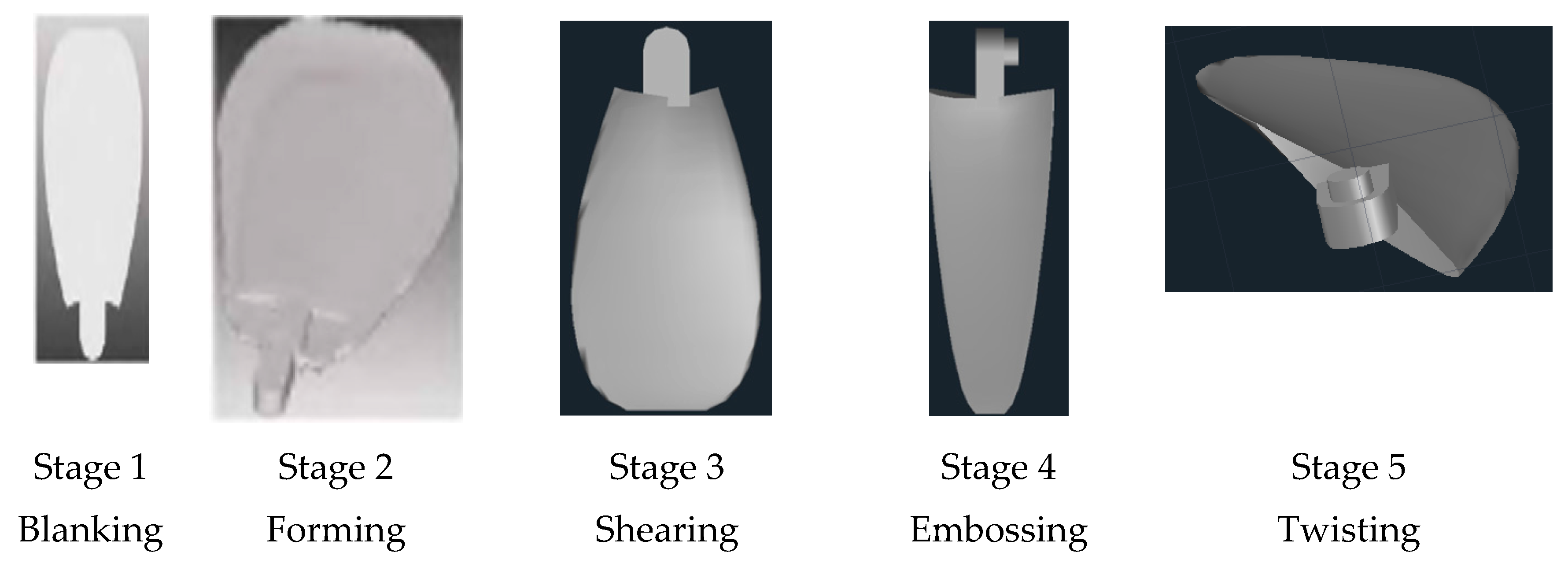
2.1. Procedure for 3D Printing by FDM

FDM 3D printing is best suited for cost effective prototypes produced with a short lead time [23]. The three major steps in 3D printing utilizing FDM technology are pre-processing, printing process and post-processing. Pre-processing involves file format conversion, configuration of the printer and preparation of the build file. The preparation of the build file takes decisions like supports, material of print, strength and resolution in the print. The process of the print starts with preparation of the 3D printer itself, which involves build plate readiness, levelling the build platform, gluing the platform and subsequently, the print command. After the print is completed post-processing starts with extraction of the printed component from the build platform. This primarily involves the dissolution of the adhesive binding the build and the platform to set the build free. The most important post-processing activity is the removal of supports and irregularities in the build. Layer lines are also generally present on FDM prints, making post processing an important step if a smooth surface is required [24].

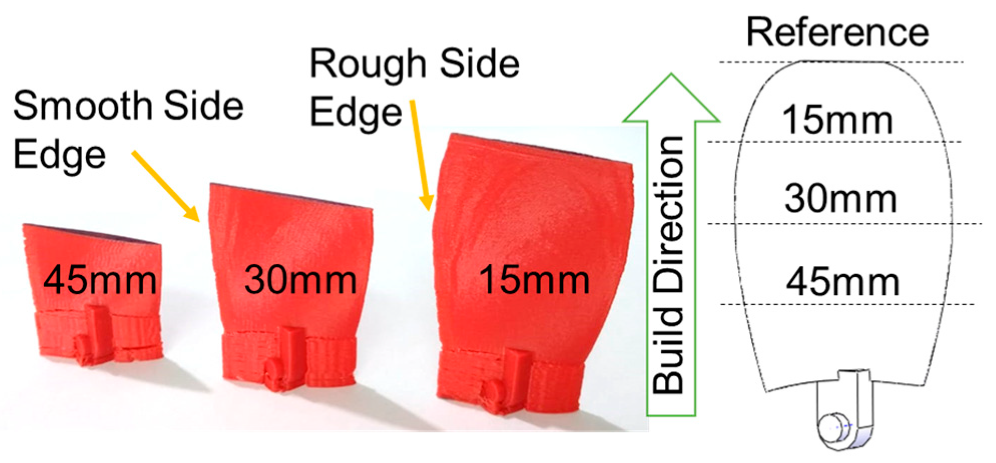
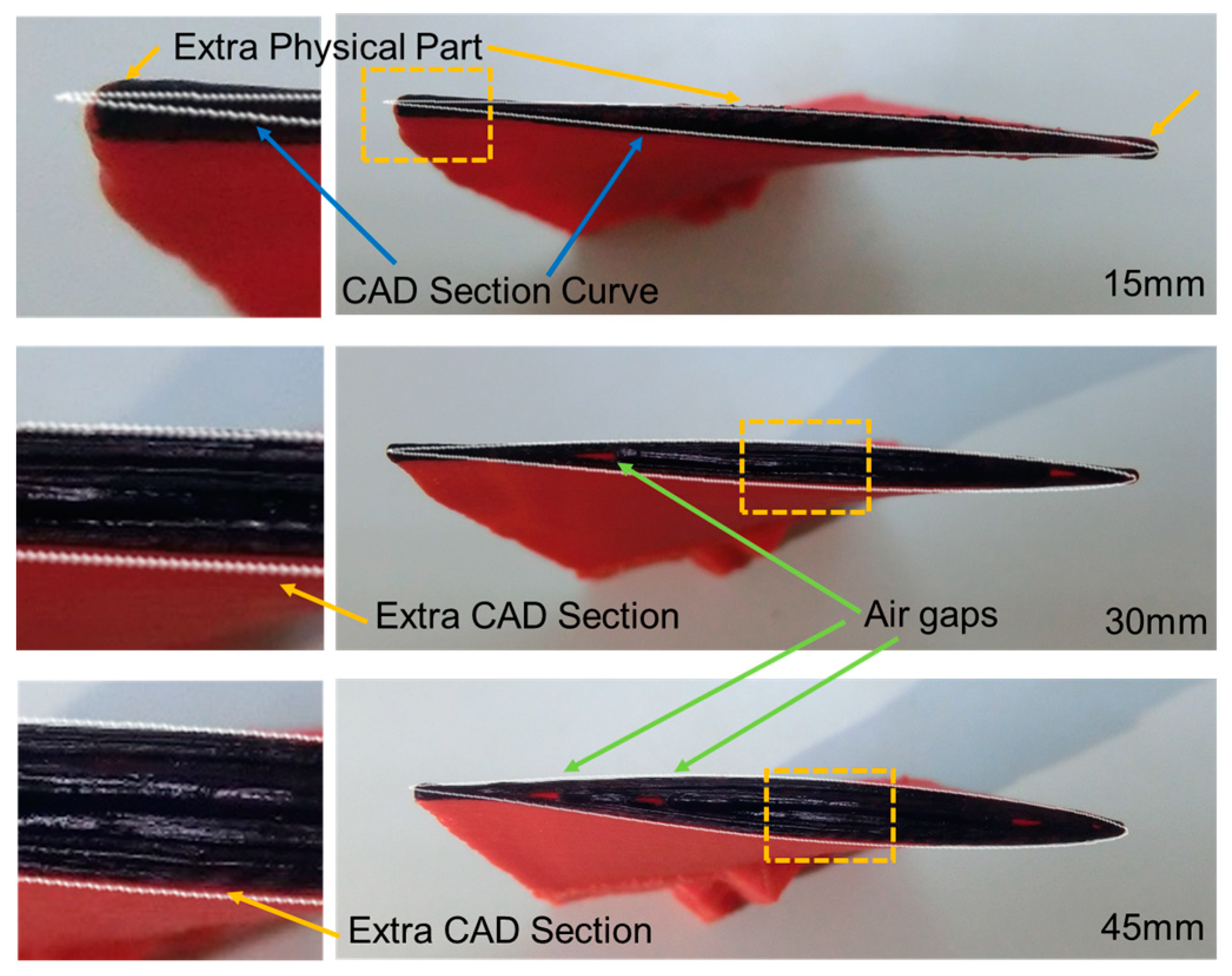
2.2. Profile Comparison and Error Measurement

The dimensional conformity of the CAD impeller model and the manufactured 3D printed physical model was compared by measuring a scaled-up (2×) impeller. Three truncated models were designed in CAD by taking the reference from the top flat portion of the impeller. These models were manufactured through 3D printing with the same parameters as mentioned above. The cross-section of each physical model was then measured physically and with the help of image-processing software Image. The CAD model and the physical model cross-sectional portion were compared by measuring area and perimeter.

3. Results and Discussion
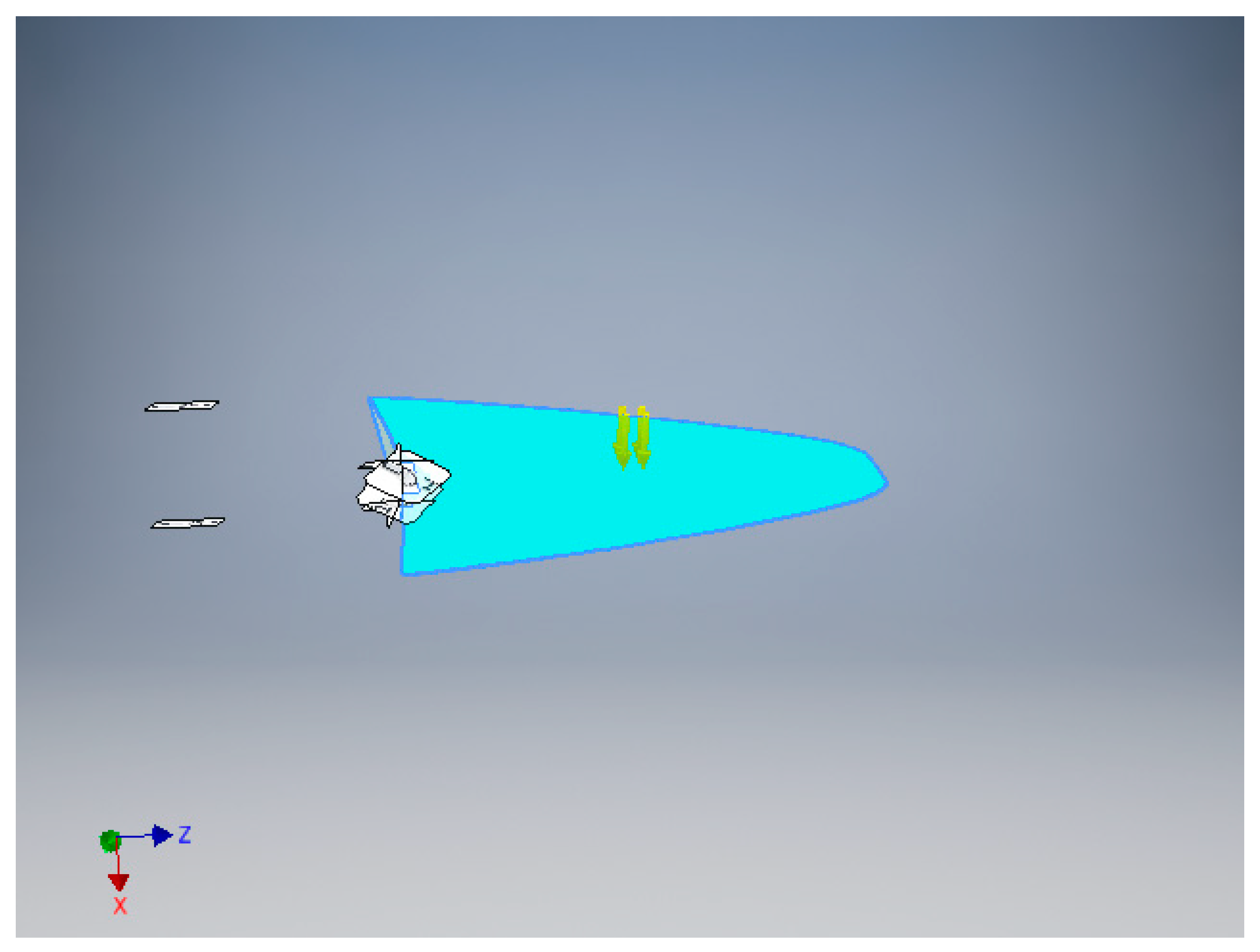
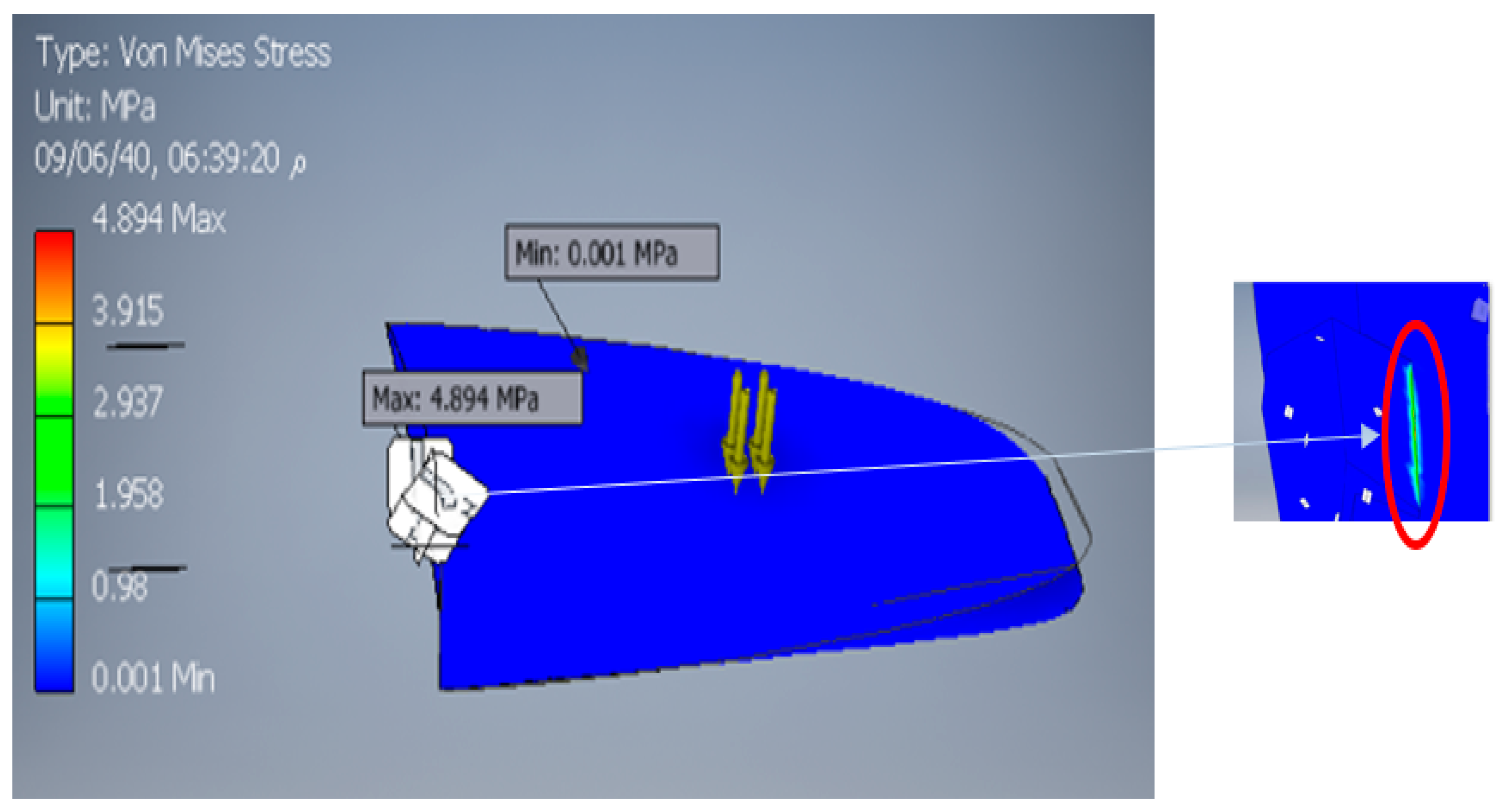
3.1. FEM Analysis

An FEM analysis of the developed component was carried out by using the software INVENTOR. Figure 2 shows the boundary conditions applied to the blade of the propeller. It is observed that at the fixed end, the maximum stresses accrued, and the displacement is maximum at the front end. Strain and stress are well within the permissible limits. Figure 3 depicts the stress distribution in the blade for the applied loading conditions. We have found that almost the whole blade was under a stress of 0.001 MPa due to the applied load. However, a small area near the hub was found to have developed the maximum stress of 4.19 MPa. For convenience, it can be said that the developed ABS blade is safe, as the Yield strength of the material is 20 MPa (Table 1), which is far higher than the maximum stress developed in the blade.
Figure 4 depicts the deflection in the blade for the applied loading conditions. It was observed that the maximum deflection that occurred in the blade was 0.01797 mm. The maximum deflection was found at the free end of the blade, which was expected due to the fixed boundary condition at the other end. The deflection of 0.01797 mm is within the allowable limit when compared with the size of the component and its material properties.

3.2. 3D Printing by FDM

Figure 5 depicts the assembled 3D printed AUV propeller with modularization of blades and hubs. The AUV propeller blade is manufactured in the five stages shown in Figure 6, which consumes a lot of time and money, [22] whereas the 3D printed AUV propeller was manufactured in one operation with comparative ease when compared to the conventional method.

3.3. Error Measurement

In order to get a better view of air flaws and dimensional accuracy, a comparison of the developed 3D printed model with that of the CAD model was carried out. This was carried out by selecting three sections at a distance of 15 mm (Figure 7) from a minimum to maximum cross-section area. The CAD model was taken as a benchmark. The cross-sectional areas have noticeable variation; however, the perimeter is not significantly different, as shown in Table 2. The highest model (Section 15) shows that the CAD cross-section was 35.5% smaller than the physical part. As the model height was decreased, the CAD model cross-sectional area became larger than the physical part. To investigate these variations, the CAD cross-sectional curve was superimposed onto the physical part, as shown in Figure 8. There were multiple reasons for CAD and physical model deviation. Firstly, the impeller is a thin shape structure, while during deposition there is no side support material. Therefore, when the physical part has many deposition layers, the lower layers expand, allowing a much higher physical cross-sectional area. This observation can be noted from Figure 5, where the sides of the impeller have rough edges when comparing Section 15 with the other two sections. Secondly, it can be safely assumed that the physical model cross-sectional values were low in number, in relation to the nozzle diameter. Near the edges, the thickness was less and thus, accurate deposition of that size was not possible, resulting in the higher area value in the physical part. At the lower height (Section 30, 45), the design had thicker cross-sections and resulted in easier deposition. However, some air gaps were observed in Sections 30 and 45, which was unavoidable in FDM, due to maintenance of the dimensional accuracy during the deposition. These air gaps were minimal and not visible to the naked eye and needed a high-resolution camera to predict their existence. This can be ignored from a design perspective. The air gaps allowed the physical part to shrink, resulting in a smaller physical cross-sectional area, as shown in Figure 8.
The perimeter of each section was nearly identical. This shows that despite the observation that the cross-sectional layers may have thickened or shrank at random locations in the lateral direction, the overall dimensional accuracy could be maintained to allow such impellers manufactured by 3D printing to have a direct application without further need for any post-manufacturing process.

4. Conclusions

An AUV propeller was manufactured in a single operation by 3D printing. The stress analysis shows that the ABS plastic propeller can withstand the loads coming onto the blades underwater. Through our analysis, we found that ABS plastic is a suitable material for AUV propellers. The error of the physical model and the required model was minimal at Section 2 of the 3 analysed sections. There were few air gaps found in the 3D printed model which were minimal and very small in size.

Author Contributions

H.M.T.K., A.N.S. and M.F.A.: concept design, experimentation and F.E.A., preparation of the manuscript. I.A.B., S.K. and T.M.Y.K.: literature review, analysis of result, review/revision, fund acquisitions.

Funding

This work is funded by Deanship of Scientific Research at King Khalid University under grant number (R.G.P. 2/11/39).

Acknowledgments

The authors extend their appreciation to the Deanship of Scientific Research at King Khalid University for funding this work through research groups program under grant number (R.G.P. 2/11/39).

Conflicts of Interest

The authors declare no conflict of interest.

References

  1. Zhangwei, C.; Ziyong, L.; Chengbo, L.; Changshi, L.; Yuelong, F.; Changyong, L.; Yang, L.; Pei, W.; Yi, H. 3D printing of ceramics: A review. J. Eur. Ceram. Soc. 2019, 39, 661–687. [Google Scholar]
  2. Ahangar, P.; Cooke, M.E.; Weber, M.H.; Rosenzweig, D.H. Current biomedical applications of 3D printing and additive manufacturing. Appl. Sci. 2019, 9, 1713. [Google Scholar] [CrossRef]
  3. Brunello, G.; Sivolella, S.; Meneghello, R.; Ferroni, L.; Gardin, C.; Piattelli, A.; Zavan, B.; Bressan, E. Powder-based 3D printing for bone tissue engineering. Biotechnol. Adv. 2016, 34, 740–753. [Google Scholar] [CrossRef] [PubMed]
  4. Martijn, T.B.M.; Tate, D.; Wang, S.; Campanile, F.; Chen, Y. Application of robust design techniques for 3D printing on textiles. Adv. Int. Syst. Comput. 2020, 975, 153–165. [Google Scholar]
  5. Jeong, H.Y.; An, S.C.; Seo, I.C.; Kim, N.; Jun, Y.C. 3D printing of plant tissue for innovative food manufacturing: Encapsulation of alive plant cells into pectin based bio-ink. J. Food Eng. 2019, 263, 454–464. [Google Scholar]
  6. Hu, B.; Duan, X.; Xing, Z.; Chen, R.; Shan, B. Improved design of fused deposition modeling equipment for 3D printing of high-performance PEEK parts. Mech. Mater. 2019, 137, 103139. [Google Scholar] [CrossRef]
  7. Ivanov, E.; Kotsilkova, R.; Xia, H.; Chen, Y.; Donato, R.K.; Donato, K.; Godoy, A.P.; Di Maio, R.; Silvestre, C.; Cimmino, S.; et al. PLA/Graphene/MWCNT composites with improved electrical and thermal properties suitable for FDM 3D printing applications. Appl. Sci. 2019, 9, 1209. [Google Scholar] [CrossRef]
  8. Gültekin, H.E.; Tort, S.; Acartürk, F. An Effective Technology for the Development of Immediate Release Solid Dosage Forms Containing Low-Dose Drug: Fused Deposition Modeling 3D Printing. Pharm. Res. 2019, 36, 128. [Google Scholar] [CrossRef]
  9. Saleem, H.; Batalha, G.F.; van Tyne, C.J.; Yilbas, B. Comprehensive Materials Processing; Elsevier: Amsterdam, The Netherlands, 2014; pp. 69–91. [Google Scholar]
  10. Melchels, F.P.W.; Bertoldi, K.; Gabbrielli, R.; Velders, A.H.; Feijen, J.; Grijpma, D.W. Mathematically defined tissue engineering scaffold architectures prepared by stereolithography. Biomaterials 2010, 31, 6909–6916. [Google Scholar] [CrossRef] [Green Version]
  11. Sano, Y.; Matsuzaki, R.; Ueda, M.; Todoroki, A.; Hirano, Y. 3D printing of discontinuous and continuous fibre composites using stereolithography. Addit. Manuf. 2018, 24, 521–552. [Google Scholar] [CrossRef]
  12. Park, H.K.; Shin, M.; Kim, B.; Park, J.W.; Lee, H. A visible light-curable yet visible wavelength-transparent resin for stereolithography 3D printing. NPG Asia Mater. 2018, 10, 82–89. [Google Scholar] [CrossRef] [Green Version]
  13. Yan, C.; Hao, L.; Hussein, A.; Young, P.; Huang, J.; Zhu, W. Microstructure and mechanical properties of aluminium alloy cellular lattice structures manufactured by direct metal laser sintering. Mater. Sci. Eng. A 2015, 628, 238–246. [Google Scholar] [CrossRef]
  14. Lahtinen, E.; Precker, R.L.M.; Lahtinen, M.; Hey-Hawkins, E.; Haukka, M. Selective Laser Sintering of Metal-Organic Frameworks: Production of Highly Porous Filters by 3D Printing onto a Polymeric Matrix. ChemPlusChem 2019, 84, 222–225. [Google Scholar] [CrossRef] [Green Version]
  15. Khan, S.Z.; Masood, S.H.; Cottam, R. Mechanical properties of a novel plymetal manufactured by laser-assisted direct metal deposition. Int. J. Adv. Manuf. Technol. 2017, 91, 1839–1849. [Google Scholar] [CrossRef]
  16. Nouri, H.; Guessasma, S.; Belhabib, S. Structural imperfections in additive manufacturing perceived from the X-ray micro-tomography perspective. J. Mater. Process. Technol. 2016, 234, 113–124. [Google Scholar] [CrossRef]
  17. Sood, A.K.; Ohdar, R.K.; Mahapatra, S.S. Improving dimensional accuracy of Fused Deposition Modelling processed part using grey Taguchi method. Mater. Des. 2009, 30, 4243–4252. [Google Scholar] [CrossRef]
  18. Wang, J.; Xie, H.; Weng, Z.; Senthil, T.; Wu, L. A novel approach to improve mechanical properties of parts fabricated by fused deposition modeling. Mater. Des. 2016, 105, 152–159. [Google Scholar] [CrossRef]
  19. Jill Manapat, Z.; Qiyi, C.; Piaoran Ye, C.; Rigoberto, A. 3D Printing of Polymer Nanocomposites via Stereolithography. Macromol. Mater. Eng. 2017, 302, 1600553. [Google Scholar] [CrossRef]
  20. Eshraghi, S.; Das, S. Mechanical and microstructural properties of polycaprolactone scaffolds with one-dimensional, two-dimensional, and threedimensional orthogonally oriented porous architectures produced by selective laser sintering. Acta Biomater. 2010, 6, 467–476. [Google Scholar] [CrossRef]
  21. Vaezi, M.; Seitz, H.; Yang, S. A review on 3D microadditive manufacturing technologies. Int. J. Adv. Manuf. Technol. 2013, 67, 1721–1754. [Google Scholar] [CrossRef]
  22. Khaleed, H.M.T.; Samad, Z.; Mujeebu, M.A.; Abdullah, A.B. Flash-less Cold Forging of AUV Propeller Blade: Work-piece Optimization and Thermal Analysis. Arab. J. Sci. Eng. 2013, 38, 2509–2519. [Google Scholar] [CrossRef]
  23. Tan, D.K.; Maniruzzaman, M.; Nokhodchi, A. Advanced pharmaceutical applications of hot-melt extrusion coupled with fused deposition modelling (FDM) 3D printing for personalised drug delivery. Pharmaceuticals 2018, 10, 203. [Google Scholar] [CrossRef] [PubMed]
  24. Haidiezul, A.H.M.; Aiman, A.F.; Bakar, B. Surface Finish Effects Using Coating Method on 3D Printing (FDM) Parts. Mater. Sci. Eng. 2018, 318, 012065. [Google Scholar] [CrossRef]
Figure 1. 3D printing machine with manufactured blades.
Applsci 09 04413 g001
Figure 2. The boundary condition applied to the blade.
Applsci 09 04413 g002
Figure 3. Von Mises stress distribution in the blade and stress contours.
Applsci 09 04413 g003
Figure 4. Blade deflection for the applied loading conditions.
Applsci 09 04413 g004
Figure 5. AUV propeller assembly manufactured by 3D printing.
Applsci 09 04413 g005
Figure 6. Formation of blade in five stages using cold forging process.
Applsci 09 04413 g006
Figure 7. Manufactured truncated models and reference from the CAD model. The arrows show the quality of side edges of the 3D printed impellers.
Applsci 09 04413 g007
Figure 8. Physical cross-sectional models and super-imposed CAD cross-sectional curves.
Applsci 09 04413 g008
Table 1. The material properties of ABS plastic.
NameABS Plastic
GeneralMass Density1.06 g/cm3
Yield Strength20 MPa
Ultimate Tensile Strength29.6 MPa
Flexural Strength75 MPa
StressYoung’s Modulus2.24 GPa
Poisson’s Ratio0.38 ul
Shear Modulus0.811594 GPa
Part Name(s)Blade1
Table 2. The measurements values of CAD and physical models.
Section NumberSection TypeCross-Sectional AreaArea VariationPerimeterPerimeter Variation
mm2%mm%
15CAD47.83−35.51%84.56−0.34%
Physical64.8184.85
30CAD83.286.04%91.660.76%
Physical78.2590.96
45CAD112.786.72%88.441.59%
Physical105.2087.03

