Article

3D Numerical Simulation of Rock Cutting of an Innovative Non-Planar Face PDC Cutter and Experimental Verification

1
School of Mechatronic Engineering, Southwest Petroleum University, Chengdu 610500, China
2
Chengdu iDrill Energy Technology Co.,Ltd, Chengdu 610500, China
*
Authors to whom correspondence should be addressed.
Appl. Sci. 2019, 9(20), 4372; https://doi.org/10.3390/app9204372
Submission received: 5 September 2019 / Revised: 11 October 2019 / Accepted: 11 October 2019 / Published: 16 October 2019
(This article belongs to the Section Mechanical Engineering)

Abstract

:
The low rock breaking efficiency of conventional polycrystalline diamond compact (PDC) bits in hard abrasive formations prompts the development of PDC cutting elements from the planar structure to the non-planar structure. As an innovative non-planar cutter, the design and research of the three-ridged diamond element (3-RDE) cutter is still in its infancy, and its rock breaking mechanism and laws are not yet clear. In this paper, a three-dimensional (3D) finite element model of dynamic rock breaking with 3-RDE cutter has been established. The accuracy of the numerical model was verified by experimental data. Then, the difference of rock breaking mechanism between 3-RDE cutter and conventional cutter was studied. The effects of back-rake angle, cutting depth, rotational angle, and rock properties on rock breaking efficiency were also analyzed. The results show that, unlike the conventional PDC shear rock breaking cutter, the 3-RDE cutter breaks rock mainly by crushing and shearing, and the rock breaking efficiency is higher. A small back-rake angle and reasonable cutting depth contribute to improving the rock breaking efficiency; the existence of rotational angle is not conductive to the rock breaking. The field application shows that compared with the conventional cutter, the 3-RDE cutter is easier to penetrate into the formation, and is more stable with less torque required. The research results can be of benefit to the design and manufacture of 3-RDE PDC bits.

1. Introduction

Currently, polycrystalline diamond compact (PDC) bits are mainly used for drilling soft to medium hard formations. While in hard abrasive formations serious failures, such as chipping, broken cutter and falling off of the PDC, often occur and the drilling effect is not satisfactory [1,2,3,4], which is difficult to meet the exploration and development needs of unconventional resources in deep formations [5,6]. To improve the performance of conventional PDC bits in deep formations, a series of approaches has been conducted on the material refinement and the design method supplement, such as increasing the number of cutters and blades [7], optimizing diamond packing [8] and using high-temperature and high-pressure (HT/HP) sintering for higher diamond volume in the PDC layer [9,10]. However, the actual improvement in field application is not obvious. Efficiently drilling with PDC in hard abrasive formations remains challenging. At present, conventional PDC bits are still not able to completely substitute the roller cone bits in deep formations.
In the last decade, with the advent of new technologies in manufacturing and depleting the catalyst material (Co) from the diamond structure, the structure of PDC cutting elements is no longer limited to a flat layer, but turns on a tendency to develop into non-planarization. In 2010, Novatek International Company initially proposed the innovative new Stinger conical shaped polycrystalline diamond element (CDE) with a thick synthetic layer (Figure 1a). The conical diamond element delivers improved wear for superior durability, and generated high point loading for effective formation fracture [11]. Later, Schlumberger Company also introduced its innovative cutter-the Axe cutter, which combines a standard cylindrical substrate with a modified ridge diamond layer (Figure 1b). Field tests indicate that this cutter improves drilling performance in terms of rates of penetration (ROP) and footage over the current PDC bits [1]. In 2015, Sifangda Company in China produced an innovative cutter with three cutting edges, called the 3-RDE cutter. Laboratory experiments show that its wear resistance and fatigue resistance are much higher than conventional cutters [12]. In addition, scholars at home and abroad have also carried out some research on non-planar cutters. Zou, et al. [13] investigated the influence of back-rake angle, cone apex angle and weight on bit (WOB) on the rock breaking efficiency of conical cutters through experiment and numerical simulation. Gumich, et al. [14] studied the rock-breaking process of axe cutters and conventional cutters, and found that axe cutters behavior better than conventional cutters in wear resistance, cutting forces required and rock breaking efficiency.
Although the non-planar cutters have shown certain potential in hard abrasive formations, related design and research are still in their infancy. Furthermore, the current study is mainly focused on the conical cutters or axe cutters. The research on 3-RDE cutters has rarely been reported in the literature. In this paper, based on elastic-plastic mechanics and rock mechanics, a three-dimensional (3D) finite element model of dynamic rock breaking with the innovative 3-RDE cutter has been established, using the extended Drucker–Prager criterion as the rock yield criterion. The accuracy of the numerical model was verified by laboratory experiments. The effects of back-rake angle, cutting depth, rotational angle, and rock properties on rock breaking efficiency were analyzed. The difference of rock breaking mechanism between 3-RDE cutter and conventional cutter was also studied. The research results could provide reference for the design and manufacture of the 3-RDE cutter.

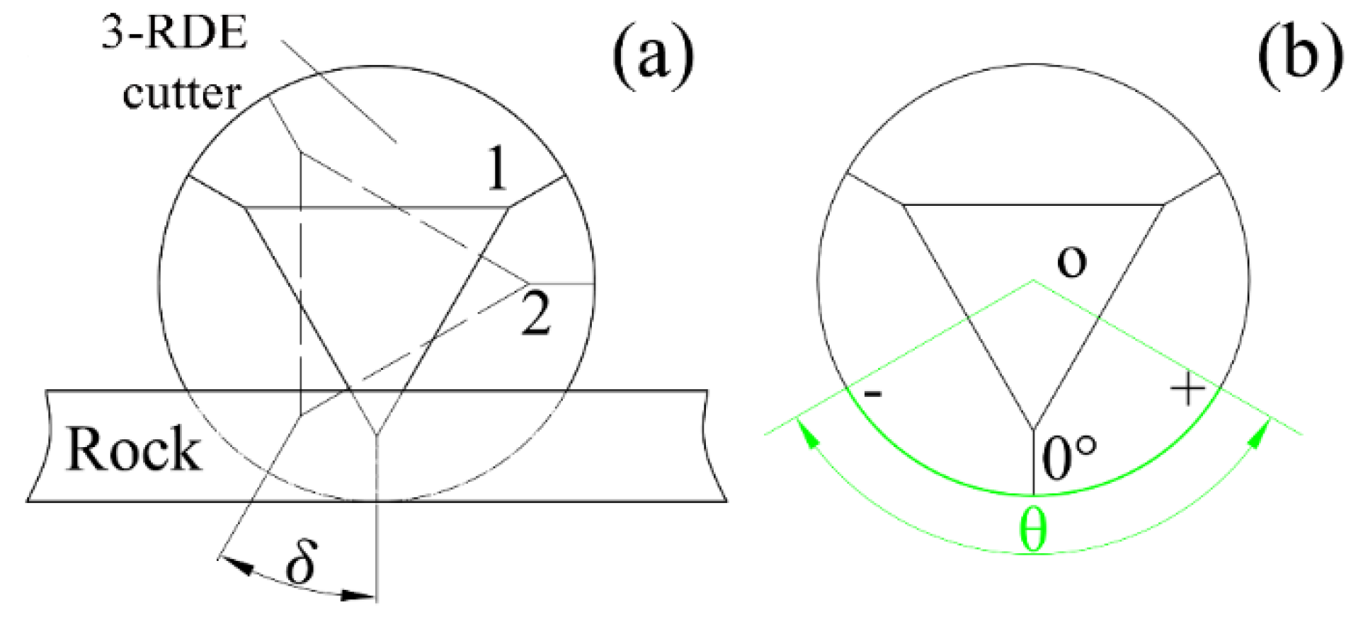
2. Introduction to 3-RDE Cutter

As shown in Figure 2b, the 3-RDE cutter has a similar cylindrical tungsten carbide base (Figure 2a); however, the diamond table is a non-planar structure represented as three convex ridges, three ramps and a central plane, which is different from the conventional plane cutter. Each ridge is formed by the interaction of two ramps (or working surfaces), which connect with the central plane by a curved transition.
The 3-RDE cutter-rock interaction is quietly different from the conventional cutter owing to its unique structure. There are mainly three aspects: (1) The convex edge of 3-RDE cutter, act as a “sharp point” to fracture the rock, which is similar to the crush action of a traditional roller cone bit; (2) the 3-RDE cutter consist of two working faces at the both sides of the convex edge, which can performs the bevel cutting and make the debris automatically formed into two branches that extruded across the working surfaces; and (3) the thickness of 3-RDE cutters’ PDC layer is greater than the conventional cutter, which indicates the 3-RDE cutter has higher wear and impact resistance.
Due to the flat structure of conventional cutters’ PDC layer (Figure 2a), the actual working angle of each point on the cutting face is consistent with the positioning angle of the cutter, such as the normal angle and back-rake angle. Although the 3-RDE cutter can be oriented by the orientation angle of conventional cutter, the actual working angle is more complicated due to the specific structure. For instance, the actual back-rake angle of two working faces, named after 3 in Figure 2b, is the combined effect of the back-rake angle of the cutter and the inclination angle of the working faces relative to the cutter’s axis. However, the cutting geometry of the 3-RDE cutter is not the content of this paper.
The profile of 3-RDE cutter is more complex than that of the conventional cutter. The main structural parameters are the diameter φ, the total height H, the height of Tungsten carbide alloy H1, the length of convex edge L1, the slope of the convex edge ζ, the angle of the and the angle η between the two working faces (Figure 3). The parameter η not only determines the working performance of the cutter, but also relates to the cutter’s life and its manufacturing cost. In this paper, the structural parameters are set as φ = 16 mm, H = 13.6 mm, H1 = 10.6 mm, L1 = 3 mm, η = 157°, and ζ = 8°. The convex edges are evenly distributed in the circumferential direction.

3. Numerical Methodology

To facilitate the analysis, the following assumptions are taken
(1)
The cutter is regarded as a rigid body, regardless of the effect of detail configurations, i.e. round borders or chamfers, of the cutting edges.
(2)
The influences of temperature, confining pressure, and drilling fluid are neglected.
(3)
When the rock element fails, it’s removed from the rock body immediately, ignoring its impact on the subsequent cutting.
(4)
Simplify the circular cutting motion to a linear cutting one [15]
(5)
The rock is continuous isotropic medium, ignoring the effects of initial cracks and internal pressure.

3.1. Strength Criteria and Failure Analysis of Rock

The extended Drucker–Prager criterion reflects the influence of volume stress on material strength, and treats the deviatoric stress as the cause of material damage, which is suitable for rock cutting research. This paper employs the linear Drucker–Prager yield surface to evaluate whether the rock element reaches the plastic state [16]
t p tan β d = 0
t = 1 2 q [ 1 + 1 k ( 1 1 k ) ( r q ) 3 ]
where p = ( 1 / 3 ) t r a c e ( σ ) ,representing the equivalent compressive stress, β is the internal friction angle of the material, d is the cohesive force of the material, t is the deviatoric stress parameter, q is the equivalent stress, r is the third invariant of the deviating stress, k represents the specific value between triaxial compressive strength and triaxial tensile strength.
When the cutter penetrates into the rock until the plastic strain of the rock reaches a certain threshold, the rock begins to be damaged. Once the plastic strain achieves the rock’s equivalent plastic strain, the rock element completely fails and peels off from the rock. In this paper, the judge criterion of plastic strain of rock-breaking is
ε p ε ¯ f p l
where ε p is the equivalent plastic strain of rock, ε ¯ f p l represents the equivalent plastic strain when the cuttings are completely damaged.

3.2. Finite-Element Model of the Cutter-Rock System

The PDC bit exhibits highly nonlinear characteristics during the rock breaking process, including geometric nonlinearity, material nonlinearity and contact nonlinearity. By adopting the finite element method, treat the spatial domain of the cutter-rock contacting system at time t as Ω , and the body force, boundary stress and Cauchy’s stress respectively as b , r , r c and σ , then the contacting issue could be represented as [17]:
Ω σ δ e d Ω Ω b δ u d Ω Γ f r δ e d S Γ c r c δ u d S + Ω ρ a 1 δ u d Ω = 0
where Γ f is the border for a given boundary force, Γ c is the contact boundary, δ u is the virtual displacement, δ e is the virtual strain, ρ is the density, a 1 represents the acceleration. By discretizing the spatial domain Ω with finite element method, one can obtain the following equation
M u ¨ = p ( t ) + c ( u , γ ) f ( u , λ )
where M is the mass matrix, u ¨ is the acceleration vector, t is the time variable, p is the external force vector, c is the contact force and friction force vector, f is the internal stress vector, u is the object displacement, γ is the variable associated with contact surface characteristics, and λ represents the variable associated with constitutive relation of materials.
According to the above theory, the nonlinear dynamic finite element model of cutter-rock system was established in ABAQUS6.14 program, shown in Figure 4. According to the Saint-Venant principle, the size of the rock is 170 × 50 × 25 mm. The 8-node reduced integration element C3D8R with high accuracy, robustness and hourglass control was employed to discrete the rock model, and the rock’s area nearby the cutter was finely meshed. The model was totally divided into 313,734 elements (331,185 nodes). And the international system of unit (m-kg-s) was applied in the numerical model, while for convenience, results were displayed according to the engineering conventions. The mechanical parameters of rock material are listed in Table 1. Non-reflecting boundary and fixed constraint were applied to the rock surfaces except the top one. The linear cutting speed of cutter is 0.3 m/s, and the diameter of the cutter is 16 mm. The contact type between the cutter and rock was eroding surface to surface. Considering the friction between the cutting surface and rock, the friction coefficient of contact surfaces was set to 0.4 [18]. In the cutting process, the reaction forces on the cutter can be divided into axial force F n , tangential force F h and the radial force F r . The tangential force is opposite to the direction of cutting speed; the axial force is along the positive direction of the z-axis, and the radial force is determined by the right-hand rule. α is the back-rake angle, and h is the cutting depth. The cutting edge of the 3-RDE cutter is always perpendicular to the upper surface of the rock in the absence of a special declaration.

3.3. Cutting Performance Evaluation Index

The cutting forces and Mechanical Specific Energy (MSE) are essential characteristics of rock breaking process. The axial force represents the ability of the cutter to penetrate into the formation axially. The smaller the axial force is, the stronger the capacity to penetrate into the formation, and the lower the required weight on bit (WOB). Similarly, the tangential force characterizes the difficulty of rock breaking. The smaller the tangential force is, the easier the rock is broken, and the smaller the torque required by the bit. Meanwhile, the MSE, which represents the energy consumed by breaking per unit volume of rock, can quantitatively represent the rock breaking efficiency, and its formula is
M S E = W V c u t = F h d S p d = F h S p
where d is the cutting stroke, the projection of cutting area S p = S l cos α l + S r cos α r (when both working faces contact with the rock) or S p = S l / r cos α l / r (when only the working face on one-side contacts with the rock), S l / r and α l / r are the cutting area and the actual back-rake angle of the working faces on the left/right side of convex edge respectively. S l / r is be obtained according to the infinitesimal method.
In the process of rock breaking, the forces on the cutters belong to impact loads, whose amplitude affects the cutter’s life. Here, the cutting forces are statistically processed. The average value is considered as an index to evaluate the cutting performance, and the standard deviation is adopted to assess the cutting stability.

4. Model Verification

An experiment on the rock cutting process is conducted to verify the correctness of the numerical model. Figure 5 reveals the experiment apparatus for rock cutting, which consists of a tool-holder, triaxial forces sensors, a data acquisition system, a rock sample and 3-RDE cutters. The planning blade is mounted on the tool-holder, and the sensors are equipped in the middle of planning blade. The 3-RDE cutter is fixed below the sensors. Strain gauges (BE120-5AA with an accuracy of 0.05 degree) are attached to the planning blade, and are bridged as sensors. The cutting forces are represented by the voltage signal collected by the data acquisition system. And according to the following formula, the cutting forces can be decoupled.
{ F n = 163.09 u n + 4.22 u h 1.32 u r F h = 24.38 u n + 8.74 u h + 1.16 u r F r = 3.43 u n + 0.12 u h + 20.65 u r
where u n , u h , u r are the axial, tangential and radial voltages of the sensors output, respectively.
The rock sample was Wusheng sandstone, whose mechanical parameters are shown in Table 1. The rock sample is fixed and the cutting depth is 1.5 mm. During the test, the cutter moves linearly with a speed 0.3 m/s. A total of five sets of tests were carried out at the back-rake angle of 5°, 10°, 15°, 20°, 25°. To avoid random errors and improve the accuracy of the experiment, each set of tests was repeated 3 times. The sampling frequency is 1000 Hz. For the convenience of analysis and comparison, the average value of axial force and tangential force, as well as MSE, are adopted to compare the experimental and numerical results, as shown in Figure 6. It can be observed that the cutting forces and MSE in simulation and experiment all gradually increase with the increase of the back-rake angle. In addition, the tangential force is greater than the axial force. That is, numerical results are basically consistent with that of the experiment in terms of values and variation laws. However, the experimental results are slightly smaller than that of the simulation, which may be due to rock heterogeneity.

5. Results and Discussion

5.1. Comparison of Rock-Breaking Mechanism of 3-RDE Cutter and Conventional Cutter

In this section, the rock breaking process with the conventional cutter and 3-RDE cutter is analyzed, respectively. The cutting depth is set as 1.5 mm. It can be obviously seen from Figure 7 that the cutting forces and their fluctuations (representing as the error bars in Figure 7a,b), as well as MSE, of 3-RDE cutter are significantly smaller than that of conventional cutter. This indicates that 3-RDE cutter can achieve a better performance than the conventional cutters, representing as a stronger ability to penetrate into the formation, less torque required, more stable cutting behavior, and higher rock breaking efficiency.
The service life is one of the important factors that determine the performance of the cutter. To some extent, the contact stress of the cutter can be employed to assess the wear of cutters [20,21]. Figure 8 shows the contact stress nephogram of conventional cutter and 3-RDE cutter. It can be seen that the contact stress of the cutters only exist in the region where the cutters interacts with the rock, while the stress in other regions is zero. However, there are significant differences in the distribution of the contact stress in the cutter-rock interaction region. For the conventional cutter, the contact stress concentrates on the bottom of the outer edge, while the contact stress, for the 3-RDE cutter, mainly distributes in the region nearby the convex ridge, forming a “convex ridge effect”. Moreover, the amplitude of the contact stress of 3-RDE cutter is just about 0.5 times of that of conventional cutter, indicating that the 3-RDE cutter can significantly reduce the contact stress. This is one of the reasons why the 3-RDE cutter has higher wear resistance than the conventional cutter.
Figure 9 shows the plastic strain nephogram during rock breaking with the conventional cutter and 3-RDE cutter. By plotting the plastic strain on the un-deformed rock shape, one can figure out that for the 3-RDE cutter the characteristics of the plastic deformation zone of the rock are significantly different from those of the conventional cutter. The former consists of an elongated “red” zone and a wide “green” zone, where the plastic strain in the “red” zone is greater than that in the “green” zone (Figure 9b). The reason for this phenomenon is that the 3-RDE cutter interacts the rock with a similar “V” shape, and the convex ridge is the first spot that contacts with the rock. Then, a large local concentrated force is generated around the tip area (the red point in Figure 10b), which is higher enough to cause plastic deformations of the rock. Finally, a local fracture is formed, releasing the rock’s internal stress. As the 3-RDE cutter continues to move forward, the working faces on both sides gradually come into contacting with the rock, and bevel the rock. Consequently, under the combined action of crushing and shearing, the rocks in front of the working faces are rapidly broken, eventually forming the combined plastic deformation zone in Figure 9b.
In contrast, the fractured area caused by conventional cutter almost entirely turns on the “red” region, and this region is significantly wider than that formed by 3-RDE cutter. Obviously, the peak of the plastic strain in Figure 9a is greater than that in Figure 9b. This can be attributed to the fact that the entire cutting area of the conventional cutter squeezes the rock synchronously (Figure 10a), and the maximum stress is located at the outer edge of the cutter, where the rock gets damaged due to shear stress. When the cutter moves forward continuously, the cutting surface squeezes the frontal rock, and finally the rock loses the coupling force and breaks.
Figure 11 shows the maximum principal stress nephogram of the rock in rock breaking with the conventional cutter and 3-RDE cutter. From Figure 11, one can notice that there exists a large tensile stress region on the rock surface under the action of 3-RDE cutter, especially the frontal region of the convex ridge, where the tensile stress is the largest. Despite the tensile stress also occurs under the action of conventional cutter, both the amplitude and distribution region are much smaller than that in the 3-RDE cutting process. Generally, the tensile strength of rock is much less than the shear strength, so the increase of the tensile stress region will be beneficial to the rock breaking, which undoubtedly results in a higher rock breaking efficiency.
In summary, due to the different shape, the rock breaking mechanism of the conventional cutter and the 3-RDE cutter is different: (1) The conventional cutter breaks rock mainly by shearing. While the 3-RDE cutter not only shears the rock in the same way as the conventional cutter, but also delivers a crushing action similar to a roller cone insert. (2) The cutting edge and working face of the conventional cutter synchronously interact with the rock, while the 3-RDE’s convex edge and working surfaces asynchronously break the rock. The forces required by the 3-RDE cutter are smaller, and the cutting process is more stable and efficient.

5.2. Effect of Back-Rake Angle

The back-rake angle is an important parameter of the PDC bit [22]. A reasonable back-rake angle not only reduces the vibration of the cutter, but also prolongs the bit life. To investigate the effect of back-rake angles of the cutter, five different back-rake angles are respectively set as 5°, 10°, 15°, 20°, 25° to carry out the numerical simulation under three cutting depth (1.0 mm,1.5 mm,2.0 mm). Effect of different back-rake angles on rock breaking is exhibited in Figure 12. Firstly, the axial force is larger than the tangential force. Secondly, the axial and tangential force increase gradually when the back-rake angle increases from 5° to 25° under different cutting depths. Meanwhile, the amplitude of cutting forces’ fluctuation gradually increases, indicating that the cutting stability gradually deteriorates, as shown in Figure 12a,b. Finally, MSE gradually increases with the increasing of back-rake angle, which means that the rock breaking efficiency narrows down (Figure 12c).
In order to further explore the effect of the back-rake angle, the plastic strain of the rock was analyzed, combined with Figure 13 and Equation (3). It can be seen that both the distribution area and the peak of the plastic deformation enlarge with the increase of back-rake angle. This might be attributed to the fact that the actual back-rake angle and the side-rake angle become larger with the increase of back-rake angle. Then, the squeeze effect of the rock in frontal of working faces is enhanced. As a result, the plastic strain becomes larger.
The above analysis shows that a small back-rake angle is beneficial to generate a large stress concentration in the cutting surface, making the 3-RDE cutter easier to penetrate into the formation and improving the cutting stability and rock breaking efficiency.

5.3. Effect of Cutting Depth

Studying the relationship between the MSE and the cutting depth is one of the basic bases for optimizing the design of PDC bits [20]. The influence of cutting depth on rock breaking with the 3-RDE cutter is shown in Figure 14. As a whole, the cutting forces increase with the increasing of cutting depth. In detail, when the back-rake angle is 15°, the axial force Fn increases from 206.32 N to 367.62 N, 546.79 N, 752.80 N, 943.26 N, and the tangential force Fh varies from 353.82 N to 635.08 N, 957.55 N, 1317.90 N, 1684.60 N as the cutting depth shifts from 1 mm to 3 mm. But visibly, the tangential force and its growth rate are significantly larger than the axial force. Meanwhile, the fluctuation of cutting forces increases significantly with the increase of cutting depth, indicating that the cutting stability gradually deteriorates, and the risk of impact failure increases.
The influence of cutting depth on rock breaking is not only on cutting forces, but also on the MSE. As shown in Figure 14c, the MSE gradually decreases with the increase of cutting depth, which means the rock breaking efficiency narrows down. This can be attributed to the fact that as the cutting depth increases, the rock breaking changes from ductile fracture with a small cutting depth to brittle fracture with a large cutting depth. The big chip formation finally forms, which reduces the repeated fracture of the rock and reduces the MSE [23]. Therefore, a proper cutting depth is of great significantly for the rock breaking efficiency of 3-RDE cutter.

5.4. Effect of Rotational Angle

As illustrated in Figure 15a, there may be two working states of 3-RDE cutter. Position 1(solid line in Figure 15a) is the ideal working position. In this state, the convex ridge is perpendicular to the upper surface of the rock. However, due to the welding or design errors, the 3-RDE cutter might be placed at Position 2 (dash line in Figure 15a), where the convex ridge is not perpendicular to the upper surface of the rock any more. In this paper, the angle between the convex ridge and the rock is defined as the rotational angle δ . To investigate the effect of rotational angles, six levels of rotational angles are respectively set as 0°,5°, 10°, 15°, 20°, 25° to carry out the numerical simulation when the cutting depth is 1.5 mm and the back-rake angle is 15°.
The contact stress nephogram in rock breaking process with the 3-RDE cutter is shown in Figure 16 under different rotational angles. Here, the polar angle θ , which represents the cutter’s region involved in the cutting, is defined (Figure 15b). The polar angle coincides with the convex ridge at 0°, the left (right) side of which is negative (positive). It can be seen from Figure 16 that under the ideal condition ( δ = 0 ) the contact stress is symmetrically distributed with the peak located at the symmetry plane of the cutter. As the rotational angle increases, the contact region gradually transitions from the area near the polar angle of 0° to the non-zero region of the polar angle. The distribution is no longer symmetrically with respect to the 0° polar angle. The unsymmetrical distribution of contact stress would result in non-uniform wear of 3-RDE cutter and reduce the cutter’s life.
The effect of rotational angles on the cutting forces and MSE is depicted in Figure 17. It can be seen that both the cutting forces and the fluctuations, as well as the MSE, increases gradually with the increase of the rotational angle, which indicates that the increasing of the rotational angle leads to the reduction of the cutter’s penetration capacity and the breaking efficiency, as well as the deterioration of cutting stability. Particularly, when the rotational angle exceeds 15°, the axial and the tangential force, along with MSE, of 3-RDE cutter are larger than those of the conventional cutter (Figure 7). This suggests that the actual breaking efficiency is not as good as conventional cutter, and the advantages of 3-RDE cutter are not shown. In addition, the radial force also increases as the rotational angle increases. The larger radial force can cause the imbalance forces on the 3-RDE PDC bit and exacerbate the lateral vibration, which may results in the premature failure of the bit. The reason for the above phenomenon is that with the increasing of the rotational angle, the balance of the radial force on the working faces are broken, and the actual back-rake angle of the working face becomes larger, and the regions of the convex edge interacts with the rock descales. As a consequence, the capacity of balancing the radial force on working forces gradually weakens.
In summary, the rotational angle has a significant impact on the rock breaking process. More attention should be focus on the brazing of 3-RDE cutter to minimize the welding error.

5.5. Effect of Rock Properties

This section simulates the process of cutting heterogeneous rocks using the following methods. Based on the secondary development of ABAQUS, the sandstone formation with a high content of gravels and the interbeded formation are respectively modeled by adjusting the distribution of Wusheng sandstone and Beibei limestone, shown in Figure 18. The physical properties of the Beibei limestone can be founded in Table 1. In the former formation, Beibei limestone is randomly distributed, while in the later formation Beibei limestone is distributed in an orderly manner.
When the cutting depth is 1 mm, the back-rake angle is 15° and the rotational angle is 0°, the tangential force in heterogeneous rock breaking with conventional cutter and 3-RDE cutter is revealed in Figure 19. It can be seen that either cutting the sandstone formation with a high content of gravels or cutting the soft-hard staggered formation, the tangential force and its fluctuation of the 3-RDE cutter are significantly smaller than that of the conventional cutter. This suggests that the 3-RDE cutter is more suitable for drilling hard and heterogeneous formations with less torque required and more stable cutting behavior.

6. Field Application

In order to verify the application of the 3-RDE PDC bit, two 3-RDE PDC bits were applied in the gravel formation and migmatitic grannite formation in the instinct of Liaohe Oilfield, China. The effects of the 3-RDE PDC bit, the Hybrid bit and the conventional PDC bit are compared when the application condition, such as the wellbore dimension, drilling parameters, depths and the lithology, are similar.
Figure 20a shows the use of the 3-RDE PDC bit and the Hybrid bit whose diameter are both 241.3 mm in Mesozoic gravel formation in the first trial. It can be seen that compared with the Hybrid bit, the use of 3-RDE PDC bit can increase the ROP by 10.9%~21.0%, along with the drilling footage increased by 1.91~2.41 time [24]. Moreover, the tripped-out bit has not been damaged and new enough to be re-tripped in, while the Hybrid bit has been worn and damaged at the shoulder (Figure 21a,b). Additionally, the application of 3-RDE PDC bit saves a Hybrid bit and times on trips.
Figure 20b illustrates the uses of 3-RDE PDC bit and conventional PDC bit with the diameter 152.4mm for drilling the migmatitic grannite formation in the second trial. Field data reveals that in a comparison of conventional PDC bit, the 3-RDE PDC bit has a 60.3% increase in ROP and a 1.2-fold increase in drilling footage, with a higher wear resistance and impact resistance (Figure 21c,d).
Field trials show that in the deep formations, both in comparison with the conventional PDC bit and the Hybrid bit, the 3-RDE PDC bit achieves a better performance in drilling footage and ROP, showing a stronger drilling capacity, higher wear resistance and impact resistance. The uses of 3-RDE PDC bit can enhance the drilling efficiency and save costs.

7. Conclusions

In this paper, a three-dimensional (3D) finite element model of dynamic rock breaking with an innovative 3-RDE cutter has been established. The extended Drucker–Prager criterion is used as the constitutive model of rock. The accuracy of the numerical model was verified by experimental results. The effects of back-rake angle, cutting depth, rotational angle and rock properties on the rock breaking efficiency were analyzed. The difference of rock breaking mechanism between the 3-RDE cutter and the conventional cutter was also studied. The following conclusions can be drawn:
(1)
Due to the different shape, the rock breaking mechanism of conventional PDC cutter is mainly shear failure, while the 3-RDE cutter not only shears the rock in the same way as the conventional cutter, but also delivers a crushing action similar to a roller cone insert with a higher rock breaking efficiency. The cutting edge and working face of conventional cutter synchronously interact with the rock, while the 3-RDE’s convex edge and working surfaces asynchronously break the rock. The forces required by the 3-RDE cutter are smaller, and the cutting process is more stable and efficient.
(2)
The cutting forces and their fluctuations, as well as MSE, of 3-RDE cutter increase with the increase of the back-rake angle. A small back-rake angle should be selected for the design.
(3)
With the increase of cutting depth, the cutting forces and their fluctuations, as well as MSE, of 3-RDE cutter increase. Reasonable cutting depth facilitates the rock breaking.
(4)
With the increase of the rotational angle, the cutting forces and theirs’ fluctuations, as well as MSE, of 3-RDE cutter increase gradually. When designing or manufacturing the 3-RDE PDC bit, the rotational angle should be set at 0° to ensure that the 3-RDE cutter’s convex edge is perpendicular to the rock surface.
(5)
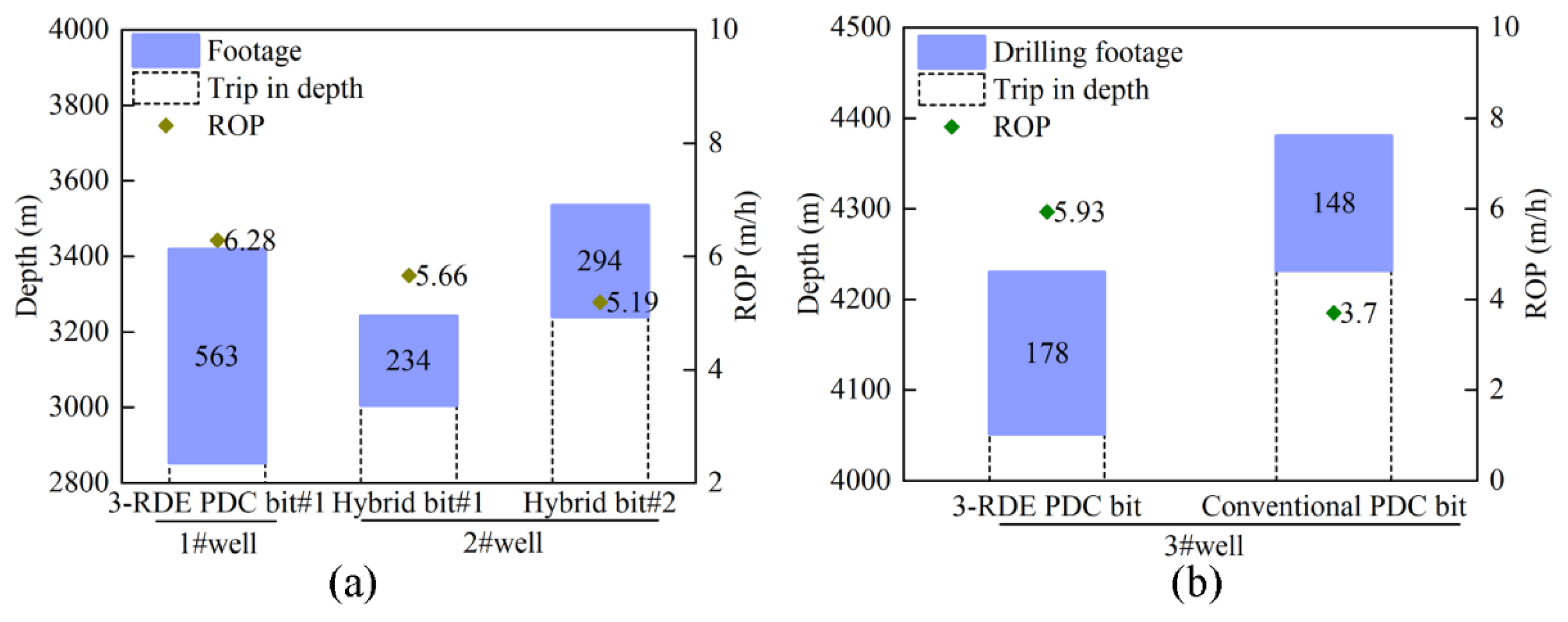
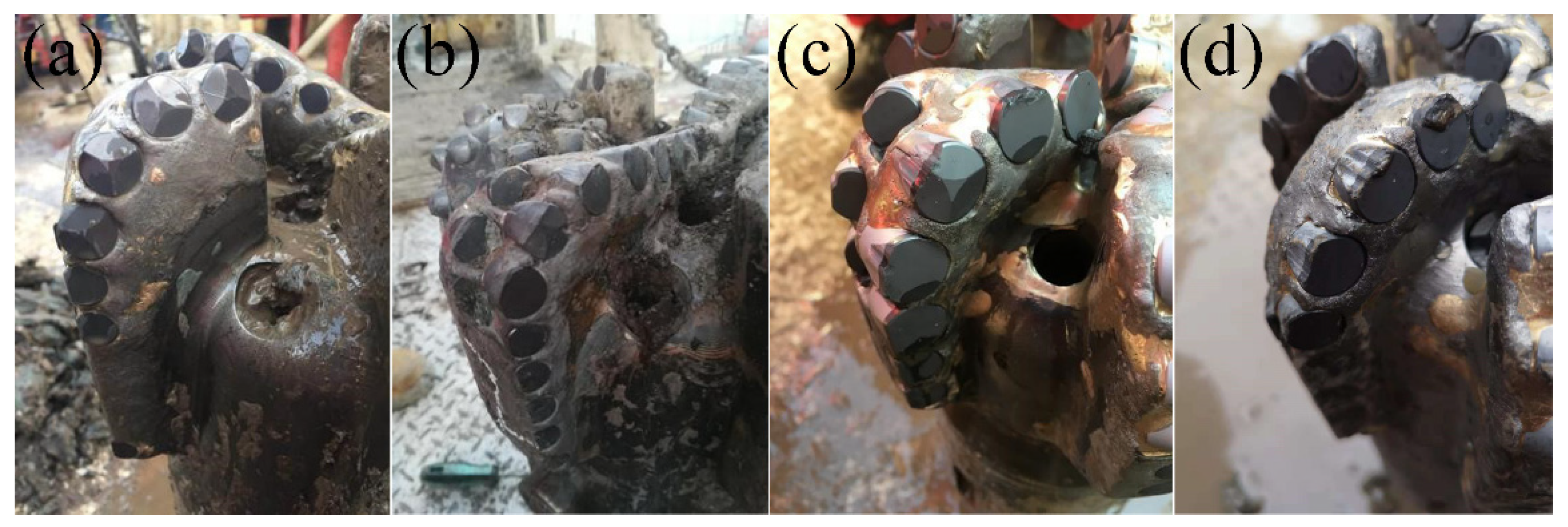
Simulation results and field trials show that compared with the conventional cutter, the 3-RDE cutter is easier to penetrate into the formation and more stable with less torque required. The use of 3-RDE cutter in hard abrasive heterogeneous formation can achieve a higher ROP and save costs.
Combined with the content of this paper, works in the future will focus on the optimization of the structure parameters and the cutting geometry of the 3-RDE cutter in order to have a better inspection for 3-RDE PDC bit design.

Author Contributions

Conceptualization and methodology, Y.K.; methodology, H.X.; software, J.L.; formal analysis and writing, J.L. and H.X.; validation. H.Z. and C.Q.

Funding

This research was supported by the National Oil and Gas Major Project of China (Grant No. 2016ZX05038005-001).

Conflicts of Interest

The authors declare no conflict of interest.

References

  1. Crane, D.; Zhang, Y.; Douglas, C.; Song, H.; Gan, X.; Lin, Z.; Mueller, L.; Skoff, G.; Self, J.; Krough, B. Innovative PDC Cutter with Elongated Ridge Combines Shear and Crush Action to Improve PDC Bit Performance. In Proceedings of the SPE Middle East Oil & Gas Show and Conference, Manama, Kingdom of Bahrain, 6–9 March 2017. [Google Scholar]
  2. Li, X.B.; Summers, D.A.; Rupert, G.; Santi, P. Experimental investigation on the breakage of hard rock by the PDC cutters with combined action modes. Tunn. Undergr. Space Technol. 2001, 16, 107–114. [Google Scholar] [CrossRef]
  3. Che, D.; Ehmann, K. Experimental study of force responses in polycrystalline diamond face turning of rock. Int. J. Rock Mech. Min. Sci. 2014, 72, 80–91. [Google Scholar] [CrossRef]
  4. Xu, C.; Gong, X.; Zhang, W.; Chen, G. An Investigation on Eddy Current Pulsed Thermography to Detect Surface Cracks on the Tungsten Carbide Matrix of Polycrystalline Diamond Compact Bit. Appl. Sci. 2017, 7, 429. [Google Scholar] [CrossRef]
  5. Yarali, O.; Kahraman, S. The drillability assessment of rocks using the different brittleness values. Tunn. Undergr. Space Technol. 2011, 26, 406–414. [Google Scholar] [CrossRef]
  6. Almasi, S.N.; Bagherpour, R.; Mikaeil, R.; Ozcelik, Y. Developing a new rock classification based on the abrasiveness, hardness, and toughness of rocks and PA for the prediction of hard dimension stone sawability in quarrying. Geosyst. Eng. 2017, 20, 295–310. [Google Scholar] [CrossRef]
  7. Che, D.; Han, P.; Guo, P.; Ehmann, K. Issues in Polycrystalline Diamond Compact Cutter–Rock Interaction From a Metal Machining Point of View—Part II: Bit Performance and Rock Cutting Mechanics. J. Manuf. Sci. Eng. 2012, 134, 064002. [Google Scholar] [CrossRef]
  8. Hussein, A.; Al-Anezi, N.A.; Al-Sarraf, A.Q.; Dhabria, A.K.; Baqer, H.A.; Maliekkal, H.; Ghoneim, O.; Zhang, Y. Thermally Stable Cutter Technology Advances PDC Performance in Hard and Abrasive Formations, Kuwait. In Proceedings of the International Petroleum Technology Conference, Beijing, China, 26–28 March 2013. [Google Scholar]
  9. Schell, E.J.; Phillippi, D.; Fabian, R.T. New, Stable PDC Technology Significantly Reduces Hard Rock Cost Per Foot. In Proceedings of the SPE/IADC Drilling Conference, Amsterdam, The Netherlands, 19–21 February 2003. [Google Scholar]
  10. Clegg, J.M. Faster, Longer, and More Reliable Bit Runs With New-Generation Thermostable PDC Cutter. In Proceedings of the SPE Annual Technical Conference and Exhibition, San Antonio, TX, USA, 24–27 September 2006. [Google Scholar]
  11. Durrand, C.J.; Skeem, M.R.; Hall, D.R. Thick PDC, Shaped Cutters For Geothermal Drilling: A Fixed Cutter Solution For a Roller Cone Drilling Environment. In Proceedings of the 44th U.S. Rock Mechanics Symposium and 5th U.S.-Canada Rock Mechanics Symposium, Salt Lake City, Utah, 27–30 June 2010. [Google Scholar]
  12. Dongpeng, Z.; Tongjian, N.; Chunlin, Z.; Shanshan, M.; Haijiang, F. Multiple-cutting-edge special shaped structure polycrystalline diamond compact. China Patent CN2015211026448, 4 December 2015. [Google Scholar]
  13. Zou, D.; Sun, Y.; YU, P.; Hou, X.; Yang, S. Experiment study on bench test of stinger PDC bit. J. China Univ. Pet. (Ed. Nat. Sci.) 2015, 39, 48–52. [Google Scholar]
  14. Gumich, D.; Pak, M.; Lomov, A.; Gorobchenko, M. New Ridge Diamond Elements Improve PDC Bit Efficiency (Russian). In Proceedings of the SPE Russian Petroleum Technology Conference, Moscow, Russia, 16–18 October 2017. [Google Scholar]
  15. Pryhorovska, T.O.; Chaplinskiy, S.S.; Kudriavtsev, I.O. Finite element modelling of rock mass cutting by cutters for PDC drill bits. Pet. Explor. Dev. 2015, 42, 888–892. [Google Scholar] [CrossRef]
  16. Yang, Y.; Zhang, C.; Lin, M.; Chen, L. Research on rock-breaking mechanism of cross-cutting PDC bit. J. Pet. Sci. Eng. 2018, 161, 657–666. [Google Scholar] [CrossRef]
  17. Zhu, X.; Yi, Q. Research and application of reaming subsidence control in horizontal directional drilling. Tunn. Undergr. Space Technol. 2018, 75, 1–10. [Google Scholar] [CrossRef]
  18. Jaime, M.C.; Zhou, Y.; Lin, J.-S.; Gamwo, I.K. Finite element modeling of rock cutting and its fragmentation process. Int. J. Rock Mech. Min. Sci. 2015, 80, 137–146. [Google Scholar] [CrossRef] [Green Version]
  19. Zhang, C. Research on Rock-Breaking Mechanism and Design. Ph.D. Thesis, Southwest Petroleum University, Chengdu, China, 2018. [Google Scholar]
  20. Tang, J.; Lu, Y.; Ge, Z.; Xia, B.; Sun, H.; Du, P. A new method of combined rock drilling. Int. J. Min. Sci. Technol. 2014, 24, 1–6. [Google Scholar] [CrossRef]
  21. Teale, R. The concept of specific energy in rock drilling. Int. J. Rock Mech. Min. Sci. Geomech. Abstr. 1965, 2, 57–73. [Google Scholar] [CrossRef]
  22. Akbari, B.; Miska, S. The effects of chamfer and back rake angle on PDC cutters friction. J. Nat. Gas Sci. Eng. 2016, 35, 347–353. [Google Scholar] [CrossRef]
  23. Liu, W.; Zhu, X.; Jing, J. The analysis of ductile-brittle failure mode transition in rock cutting. J. Pet. Sci. Eng. 2018, 163, 311–319. [Google Scholar] [CrossRef]
  24. Trunk, P.; Nasief, M.; Shi, K.; Long, W.; Terracina, D.; White, A.; Tocantins, J.P.; Costa, E.; Louback, L.; Hird, J.; et al. Underreamer Block with Conical Diamond Elements—Concept, Design, Optimization, and Field Tests. In Proceedings of the SPE Annual Technical Conference and Exhibition, Dallas, TX, USA, 24–26 September 2018. [Google Scholar]
Figure 1. Illustration of non-planar cutters: (a) Conical cutter; (b) Axe cutter; (c) 3-RDE cutter.
Applsci 09 04372 g001
Figure 2. Illustration of (a) Conventional planar-cutter and (b) Three-ridged diamond element (3-RDE) non-planar cutter.
Applsci 09 04372 g002
Figure 3. Structure parameters of 3-RDE non-planar cutter: (a) Top view; (b) Main view; (c) Section view.
Applsci 09 04372 g003
Figure 4. Finite element model of the cutter-rock system: (a) Axonometric view; (b) Right view.
Applsci 09 04372 g004
Figure 5. Experimental apparatus.
Applsci 09 04372 g005
Figure 6. Comparison between the numerical and experimental results: (a) The axial force; (b) The tangential force; (c) The Mechanical Specific Energy (MSE).
Applsci 09 04372 g006
Figure 7. Comparison of cutting forces and MSE between conventional cutter and 3-RDE cutter: (a) Fn; (b) Fh; (c) MSE.
Applsci 09 04372 g007
Figure 8. Contact stress in rock-cutting process: (a) Conventional cutter; (b) 3-RDE cutter.
Applsci 09 04372 g008
Figure 9. Plastic strain in rock-cutting process: (a) Conventional cutter; (b) 3-RDE cutter.
Applsci 09 04372 g009
Figure 10. Von Mises of rock under the action of (a) Conventional cutter and (b) 3-RDE cutter.
Applsci 09 04372 g010
Figure 11. Major Principal Stress in rock-cutting process: (a) Conventional cutter; (b) 3-RDE cutter.
Applsci 09 04372 g011
Figure 12. Effect of back-rake angle on: (a) Fn; (b) Fh; (c) MSE.
Applsci 09 04372 g012
Figure 13. Plastic strain in rock-cutting process: (a) α = 5°; (b) α = 10°; (c) α = 15°; (d) α = 20°; (e) α = 25°.
Applsci 09 04372 g013
Figure 14. Effect of cutting depth on: (a) Fn; (b) Fh; (c) MSE.
Applsci 09 04372 g014
Figure 15. Illustration of (a) Rotational angle (b) Polar angle.
Applsci 09 04372 g015
Figure 16. Contact stress distribution of 3-RDE cutter under different rotational angles.
Applsci 09 04372 g016
Figure 17. Effect of rotation angles on cutting forces and MSE.
Applsci 09 04372 g017
Figure 18. Heterogeneous formations: (a) The sandstone formation with a high content of gravels; (b) The soft-hard staggered formation.
Applsci 09 04372 g018
Figure 19. Response of tangential force in heterogeneous formations: (a) The sandstone formation with a high content of gravels; (b) The soft-hard staggered formation.
Applsci 09 04372 g019
Figure 20. Application of (a) 3-RDE PDC bit and Hybrid bit in gravel formation; (b) 3-RDE PDC bit and Hybrid bit in migmatitic granite formation.
Applsci 09 04372 g020
Figure 21. Pictures of bits after field trials: (a) 3-RDE PDC bit in gravel formation; (b) Hybrid bit in gravel formation; (c) 3-RDE PDC bit in granite formation; (d) Conventional PDC bit in granite formation.
Applsci 09 04372 g021
Table 1. Mechanical parameters of rock material [16,19].
Rock SampleElastic Modulus/GPaPoisson’s RatioTensile Strength/MPaShear Strength/MPaCompressive Strength/MPaFriction angle/°
Wusheng sandstone11.540.0624.34613.5667.54838.03
Beibei limestone31.20.1716.75817.72105.95143.62

