Article

Definition of the Layout for a New Facility to Test the Static and Dynamic Stability of Agricultural Vehicles Operating on Sloping Grounds

by
Marco Bietresato
* and
Fabrizio Mazzetto
Faculty of Science and Technology, Free University of Bozen/Bolzano, Piazza Università 5, I-39100 Bolzano, Italy
*
Author to whom correspondence should be addressed.
Appl. Sci. 2019, 9(19), 4135; https://doi.org/10.3390/app9194135
Submission received: 25 June 2019 / Revised: 26 September 2019 / Accepted: 27 September 2019 / Published: 2 October 2019
(This article belongs to the Section Mechanical Engineering)

Abstract

:

Featured Application

This study illustrates a reasoned design process that conceptually defines a project of a test rig on the basis of the tests that it must be able to perform when in operation. It has been applied to the design of a structure to test the stability of agricultural machinery.

Abstract

In this study, a new rig for investigating the static and dynamic stability of agricultural machines was conceived: its architecture was studied and its layout was designed following a specific conceptual approach. The first part of the proposed design process specifically addresses the test equipment and follows a ‘top-down’ logic starting from the requisites of the tests to perform. This approach alternates analysis and synthesis phases and exploits two important principles of the creative design process: functional analysis and decomposition, and kinematic inversion. During this process, many solutions (kinematic mechanisms, actuators) were proposed and discussed based on their advantages and disadvantages towards the definition of an optimal configuration. Therefore, the layout of a new mechanical system has been developed, which is supposed to steer subsequent and more detailed design-phases appropriately. The proposed facility has many innovative features compared to traditional test systems, in which vehicles are tested for lateral overturning under static conditions with the steering components (wheels/central joint for conventional/articulated vehicles) usually in a configuration corresponding only to a straight-path trajectory. Indeed, the present test rig is a mechanical installation with three degrees of freedom. It presents a wide plane, which can be tilted, composed by two semi-platforms connected by a central articulation hinge, operated by hydraulic jacks which allow the different angulations of the semi-platforms. It is specifically thought for performing dynamic stability tests of vehicles, especially on circular trajectories. An additional subsystem embedded in one of the two semi-platforms, configured as a rotating platform (‘turntable’), can test the global (static) stability of motionless vehicles placed on it.

1. Introduction and Background

1.1. The Problem of Rollover of Agricultural Machines

The constantly increasing demand for agricultural products has led to the cultivation also of areas that are non-ideal for mechanization due to the geo-orographic conformation of the land, particularly due to very steep sloping-grounds, albeit with interesting agronomic characteristics in terms of climate and solar radiation. Similarly, the need for farms to remain competitive on the market imposes a growing use of machines worldwide with the aim of: speeding the operations on the crops and increasing the timeliness of plant-protection treatments, reducing the time-to-market from the ripening of the agricultural product to be collected, and, above all, increasing the overall field yield. Extending the use of machines to environments that present objective difficulties for cultivation has led operators to work in conditions with high rollover risk [1,2,3,4,5,6,7,8] and aggravating loads (e.g., with the machine operating at its limit of carrying capacity or with the center of gravity—CoG—offset from the vehicle median line). Additionally, the same stability problems exist also in other working conditions, generally less dangerous in theory (e.g., agricultural operations carried out on a plane surface), yet still at risk of potentially-critical situations (e.g., sluices, asperity of the soil). Therefore, accidents due to the overturning of machines continue to occur nowadays with high frequency, and often have serious or even fatal consequences for the people involved. Indeed, statistics show that most of the fatal accidents happen when a farm tractor overturns [9,10,11,12,13,14,15], mainly due to the widespread use of these machines, their high CoG, and the absence of suspensions in combination with uneven grounds. In particular, Mashadi and Nasrolahi [16] report that over 50% of fatalities in agricultural accidents per year are due to the rollover of tractors. From a human and social point of view, the cost of these accidents is very high and justifies a continuous research commitment in this domain [17,18]. For the described reasons, the mechanization of side-slope activities [19] and the dynamic behavior of off-road vehicles in general has been studied since the 1950’s, especially with regard to the vehicle-terrain interaction [20], and it is still an open field of investigation. Since then, quite a few publications have been published on this topic, especially in the terramechanics and field robotics literature—such as the work by Peters and Iagnemma [21]—as well as many others addressing tractor stability and the reduction of injuries related to tractor rollovers [17,22].

1.2. Approaches to the Problem, Actual Tests of Stability, and the Need for a New Test Facility Concept

The key point to ensure the operators’ safety as well as the operability of a machine is the full knowledge of the stability performance of agricultural machines. The critical parameter is the CoG position as a function of other constructive parameters, also in vehicle operating configurations that foresee the presence of payloads or mounted/trailed implements [23,24,25,26], or of a battery pack as a consequence of the electric hybridization of a conventional vehicle [27]. As acknowledged in literature, the CoG position affects the operation of any active-safety device acting on several on-board technical systems [16,28,29,30,31]. Every passive- or active-safety controller (or, generally, every control strategy to correct or optimize the trajectory of a vehicle) is based on the knowledge of the CoG position to infer the vehicle dynamic behavior and perform trajectory optimization for given initial conditions [32,33,34]. In addition, the capability of leveraging the CoG position could be the starting point to redesign or modify a tractor by varying its wheelbase, track width, front-axle mounting point or other design parameters [3,35]. Consequently, the study of the CoG position is a hot topic both for the scientific community and for the manufacturers of vehicles and, in particular, of agricultural machinery.
Several studies on vehicle stability have approached the problem of characterizing the stability of machines primarily from two points of view:
  • Theoretical–numerical [4,35,36,37,38,39]: By modeling a vehicle in terms of masses, constraints and supports, and developing equations in more or less complex simulators, as done by Abu-Hamdeh and Al-Jalil [25], suitable to calculate the position of the CoG of the machine possibly with some mounted implements and trailers [23,24], thus predicting the static conditions and the security level for many inclinations of the supporting plane. For example, several scholars [1,5,36,37] use an analytical-Newtonian approach combined with a kineto-static approach based on rigid bodies. In some cases, these simulators have allowed to simulate the dynamics of a vehicle also in terms of response to an external disturbance: therefore, they have been used to investigate the robustness and fine-tune the characteristics of the software controllers that could be installed on such vehicles [32,33,34].
  • Practical–experimental [22,40,41]: Using a dedicated test-facility, by following, developing or refining the test methods/procedures described by the legislation in force, e.g., ISO 789-6 [42], ISO 16231-2 [43], SAE J2141 [44], and SAE J2926 [45]. Other than obtaining a characterization of the tested machines which is very useful for comparisons or homologations, the same data can be used to set the operation of several active-safety devices, which include sensors connected to actuators, or simply alarms for the driver [16,28,29] based on the real behavior of vehicles registered in many field-tests. Hence, this approach takes into account all the disturbing factors that normally occur during the everyday use of a vehicle.
In particular, as for the experimental methods and the related equipment, it is possible to distinguish two types of tests:
  • Tests aimed at the detection of the (relative) spatial position of the vehicle center of gravity (i.e., the three coordinates of the CoG, referred to a frame of reference fixed to the vehicle), e.g., by lifting the vehicle in two different points and measuring the weight supported by the wheels and the lifting system [43,46], or at least aimed at determining the height of the CoG from the supporting surface (e.g., pendulum test) as proposed by Fabbri and Molari [47]. Wang et al. [48] inquired also the influence of springs, fuels, hydraulic oil, lubrication oil and elastic cells on the CoG measurement accuracy by lifting a vehicle, specifically a mower.
  • Tests designed to characterize the vehicle with reference to its tilt angle (usually referred to as side inclination), regardless of the exact knowledge of the CoG position but, rather, directly observing the effects of its spatial placement in terms of stability/overturning of the whole vehicle. These tests are very simple albeit effective: the vehicle to be tested, equipped with its own tires (i.e., in a condition as close as possible to real world applications), is placed on a ‘tiltable’ flat platform and the angle of the platform necessary to have a side overturning of the vehicle is identified. In the last few years, some variations/improvements of the classic flat-platform test were proposed. For example, Gravalos et al. [3] developed a test bench able to measure the reactions on the wheels of a vehicle under static load with a gradual increase of the vehicle roll angle, thereby investigating the effect of the rear-track width and of an additional weight on the wheels on the stability. Similar variable-tilting testing devices have been used in the field of off-road robotics. Lindemann and Voorhees [49] used a 16-foot square ‘tiltable’ table, the Variable Terrain Tilt Platform (VTTP), to test the ability of a model of the Mars Exploration Rover. The vehicle was driven on the VTTP at 0–20 degree slope angles, at different orientations to the slope, while simultaneously traversing over obstacles up to 25 cm in height. This allowed to quantify the translation down the slope and the vehicle slip as a percentage of total drive over two different surfaces. The same results were also used to validate the vehicle–terrain interaction model in the physics-based “ROAMS” rover simulator [50]. Inotsume et al. [51] used a tiltable sandbox, 2-m-length and 1-m-width, capable of being inclined up to 20 degrees, to test the slippage experimented by a reconfigurable planetary rover on a slope-traversing path. Finally, in the study by Scarlett et al. [52], a pre-fabricated steel spiral roll-over ramp was used to provoke the vehicle lateral roll-over. This ramp had an initial side-slope of 18° and a final slope of 55°, with the side angle increasing progressively along the ramp length.
The tests of the second type, using a tiltable flat platform, are surely more common for farm tractors: the equipment for performing such tests is often available even at the tractor production facilities. Nevertheless, such tests have some limitations. Firstly, they are referred to a specific static overturning condition (typically a side-overturning), and the vehicle steering components (wheels, central joint) are positioned as for a straight-path trajectory. However, the most dangerous situations happen during turning maneuvers, so a further investigation is worthwhile since the supporting polygon could be modified [1,5,6,23] when the steering wheels or the two halves of the vehicle (respectively, for traditional/articulated vehicles) are angled, and the speed contributes with a destabilizing effect during turns due to the centrifugal force. For these reasons, articulated tractors are tested also according to the norms foreseen for other types of vehicles with an articulated chassis and central steering joint, i.e., telehandlers, pallet stackers, double stackers, and order-picking trucks [53,54]. As explained in [55], the additional information that can be obtained by performing this type of test does not yet provide a complete knowledge basis of the behavior of articulated tractors because the test configuration relates to a single steering angle. Furthermore, such angle is dependent on the dimensions of the vehicle support polygon, thereby preventing test data of different vehicles from being fully comparable with each other.
Another critical situation takes place when a tractor exits an inter-row (i.e., a terracing) of a field placed on a hillside: there could be a sharp change in the slope and one of the wheels might not be able to touch the ground (Figure 1).
Hence, the only possibility of overcoming the existing test systems and their limitations is to develop a novel experimental facility able to evaluate the static and dynamic stability of machines by means of new and unconventional tests.

1.3. Aims of the Research

Since the final target is to conceptualize a new facility to be used alongside test facilities and test methodologies consolidated over time, it is necessary to adopt a structured design-approach. One of the most popular frameworks to schematize engineering design cycles has been properly integrated with a classical test-design procedure, to obtain a complete ‘top-down’ approach specifically intended for designing test systems starting from the test trials to be implemented.
Therefore, the aims of the present article are the following:
  • To present the approach for the definition of the new tilting platform. Despite it being derived from the methodology for the development of a generic product, it has been properly customized to the development of a test structure (Figure 2) to have an effective simulation of a scenario to be investigated; indeed, the proposed design process goes a step further in conceptualization because it starts from the technical characteristics to be investigated on the object (in this case, agricultural vehicles) of the future tests to be performed by means of the test rig being developed;
  • To illustrate the most important characteristics (sub-systems, functionalities, constructive solutions) of the test rig to study the stability of agricultural machines, arisen from the application of the design-process, illustrated as a set of embodiment design alternatives. As will become evident in the following paragraphs, the design of the proposed test rig, intended as the product architecture (i.e., the layout of the functional components of the rig and of their operation), is quite different from that of existing test rigs, which are generally more trivial and more limited in terms of number of functions/tests to be performed. Therefore, keeping in mind the safety of agricultural machinery operators and the equipment nowadays available to testers, we proceed to present the many new elements of the final concept, starting from its layout and the features which are relevant in decision-making and which can be starting points for future works.

2. Materials and Methods: The Design Approach

A test rig for agricultural machinery is a mechanical system of very high strength and resistance since it must support a whole agricultural machine. Most importantly, it must grant the possibility of moving some of its subsystems via actuators to change its configuration. Although the design objectives are given for this specific task, the design process could be rather complex, as abstract design-stages are still in play. Indeed, the objectives have not yet been translated into technical requirements. According to one of the most popular frameworks to schematize engineering design cycles (Pahl et al. [56]), the steps to be followed in this case-study are:
  • Conceptual and embodiment design;
  • Detailed design;
  • Manufacturing, construction, installation, and inspection.
The present paper focuses only on the first phase. The activities covered within this phase are not standardized by their very nature, as claimed by Bacciotti et al. [57], because they leverage the designers’ creativity to a large extent. However, they can be structured and supported by logical reasoning and engineering knowledge, similarly to what was presented by Yavuz [58] for mobile robots or, in general, to what proposed by Fu et al. [59] for the design of kinematic systems.
The approach presented here and followed in the development of the test rig subdivides the first phase into six sub-phases (“steps”). The functional analysis and functional decomposition principles [60,61] are applied iteratively, both to the whole system (i.e., the whole test rig for agricultural machines) and to each subsystem (e.g., the general structure, the inclination system, the semi-platforms angulation system, the subsystem for performing global static stability tests), according to a top-down logic (Table 1).
The very first step of phase 1 (step 1.a) deserves further clarification. Indeed, since in this case the system to be designed is a test rig, a specific approach for this kind of products/devices could be favorably used. It mirrors the structured approach that is normally applied (e.g., in the field of base and applied sciences) to design a test or experiment starting from a real situation/phenomenon to be investigated (Figure 3), extended in this case with a further step to reach the concept of the test system [55]. The behavior conditions to be replicated are later identified and isolated due to their relevance to the present study. The subsequent steps then aim to define a piece of test equipment able to simulate a controlled situation (here: a moving or motionless agricultural vehicle on a slope solicited by forces with different directions) and, thereby, to generate a response that is intelligible, reproducible and also representative of reality (here: the real working conditions of a farm tractor on hillsides).
Subsequently, as illustrated in Table 1, after the conceptualization of a general idea about the system (here: an innovative facility for testing moving and motionless vehicles on a slope; step 1.a), the minimum system requirements and the constraints to which the system is subjected have been defined and translated into technical specifications that the system should have (e.g., minimum dimensions, minimum achievable inclination-angle; step 1.b). In the following step 1.c, the system architecture has been designed (conceptual/CAD sketches of some subsystems) following certain criteria (e.g., regarding the actuators). During this phase, the creativity of the designer is essential but can be guided by one or more of the many approaches hitherto proposed in the literature [62], the most famous of which are based on the creation of components/blocks with proper interfaces of connection and on the study of relative interactions/movements/ways of operating [63,64]. Therefore, by reasoning on such schemes, some linear actuators were placed so that the desired movements (partial rotations of some machine components) take place in correspondence to the full extension of the actuators. All ideas in this phase have been initially accepted without considering the feasibility and the system dimensions, much resembling a brainstorming session for a group of people. Then, the operation of the system has been preliminary studied (step 1.d) with the aim of selecting the most interesting schemes/ideas, and further refinements to the design have been done (steps 1.e, 1.f). At the end of this design phase, several schemes and CAD-drawings of the system and the adopted solutions are made available. These outputs can be used in the following phase (phase 2) to guide the action of a designer. The final design of such test facility could possibly benefit from the application of an approach similar to the ‘V-model’ used in model-based design (especially in the software development process). Indeed, the ‘V-model’ process emphasizes requirement-driven design and testing, so the initial concept is modified when data are gathered from numerical simulations and experiments. The detailed dimensioning of the system components (including, e.g., the development of a static model of the system and of its components, the choice of the structural components from catalogues, the choice of the materials to be used, the calculation of the thicknesses and a fatigue analysis of some components, if necessary) does not relate to phase 1 of the general design-process (‘Conceptual and embodiment design’) [62,65,66,67]: it is instead a subsequent process (‘phase 2’) and therefore has not been addressed here.

3. Application of the Design Approach to the Definition of the Innovative Test Rig

3.1. Design of the General System (‘Test Rig’)

3.1.1. Conceptualization of the General Idea of a System ( Step 1.a)

Following the specific approach for conceiving and designing a test system, it is necessary to define the typical situations leading to a sideways overturning or a lateral rollover of an agricultural machine. In particular, the overturning conditions are essentially three [37,68,69], possibly occurring together to outline many possible scenarios:
  • The machine is travelling across a gradient on a flat (but not horizontal) support plane, in particular along a route not aligned with the maximum slope direction;
  • The machine is travelling along a straight path when a local modification of the ground slope is met by one wheel [70], e.g., an obstacle, a rut, or a hole in the trajectory (i.e., the support plane is horizontal but not flat and hence it is locally not horizontal and at least one wheel can lose contact with the soil);
  • A vehicle performs an abrupt turn without modifying its speed, which is excessive for the chosen turning radius (i.e., the weight-force is deviated from the perpendicular direction of the support plane by the centrifugal force).
To analyze these three scenarios, it is necessary to consider that, in general, a rollover of a vehicle happens when the vector, which is the sum of the forces applied to the vehicle CoG, has a direction not intersecting the vehicle support polygon, linking the traces of all the wheels/tracks (but not necessarily lying on a horizontal plane). The forces acting on the CoG are at most two:
  • the gravity force (always present), perpendicular to the supporting plane only if the latter is horizontal;
  • the inertial force, present only for vehicles moving at a not-constant speed on a straight trajectory (i.e., if a vehicle accelerates or decelerate) or following a non-straight trajectory (i.e., if a vehicle changes its trajectory/makes a turn).
There are other forces acting on the vehicle, i.e., those coming from the interaction with the terrain, balancing the forces acting on the CoG in accordance with the Lagrange–d’Alembert principle.
A possible classification of any overturning scenario can be done according to the presence or not of the inertial force, or, rather, based on the velocity of the vehicle CoG: if the velocity remains substantially constant (in magnitude and direction) during a maneuver, the possible overturning can be named ‘quasi-static’. Vice versa, if the velocity changes (in magnitude and/or direction), the possible overturning can be classified as ‘dynamic’.
When the overturning happens in a lateral direction, the vehicle undergoes a side overturning and the above-enunciated rollover condition can be re-formulated in two dimensions, observing the layout of the forces in the transversal plane (Figure 4). Any possible component of the forces (gravity, inertia, interactions with the terrain) in the direction of the vehicle longitudinal axis has no influence for the incipient lateral rotation of the vehicle. If the vehicle is turning, the radial component of inertial force is commonly called ‘centrifugal force’ in the vehicle frame of reference, i.e., a non-inertial frame of reference. The centrifugal force is perpendicular to the tangent to the vehicle trajectory, and it points outwards from the curve [71].
Similarly to what was done before for the classification of a generic overturning, the side-overturning can be also classified on the basis of the absence/presence of the inertial force (here: the centrifugal force). Therefore, the presented scenarios can be classified as follows: the first two scenarios are ‘(quasi-)static’ (centrifugal force negligible), while the third one can be properly defined ‘dynamic’ (centrifugal force determinant in the destabilization of the vehicle). According to this subdivision, the tests required to characterize the stability of a vehicle will therefore be of two types: ‘static’ (motionless vehicle) and ‘dynamic’ (vehicle moving along a circular trajectory with a constant speed). These two scenarios can be further investigated by considering other variables, e.g., the angle between the vehicle longitudinal axis and the support plane maximum slope direction, the angulation of the steering wheels, any additional mass if required (frontal/rear/lateral mounted implements, carried payloads). A special case could be represented by all those situations that involve a spatial relocation of the vehicle masses in relation to the support polygon, e.g., due to the presence of: a moving loader on the front, a moving backhoe on the back, a moving crane boom with a suspended load, or a moving manipulator arm. In this case, although the inertial force would still have an effect, with the kinematic condition on the CoG used as classification key we can still consider the situation as static. As will be discussed in the following paragraphs, the proposed classification is fundamental for stating the type of tests that the test rig will be able to perform, and hence its architecture.
Finally, to complete the possible scenarios of overturning, the elastic properties and plasticity limits of the terrain must be considered since it can compact unevenly under vehicle load, and the support offered to the vehicle below each tire or track can fail, thus worsening the situations described in each of the three presented scenarios.

3.1.2. Definition of General Requirements (Step 1.b)

Therefore, the test rig under development must be able to perform the following tests:
  • Static tests of a vehicle that is placed, motionless, on a sloping support. Its steering components (wheels, central joint) can be oriented as to follow a straight-path trajectory or to perform a steering maneuver. The trials are repeated with several inclinations of the support. If there is some equipment (backhoe, crane boom, arm, etc.) that can assume different positions, the listed tests can be repeated with this equipment fixed in several different positions or moving at different speeds. The static tests can assess:
    o
    lateral stability (classic test of lateral-rollover; Figure 5a); in this test the longitudinal axis of the vehicle and the maximum slope direction are perpendicular;
    o
    longitudinal stability (classic test of longitudinal stability, or hopping test); in this test the vehicle longitudinal axis and the maximum slope direction are aligned, and the vehicle front part is uphill;
    o
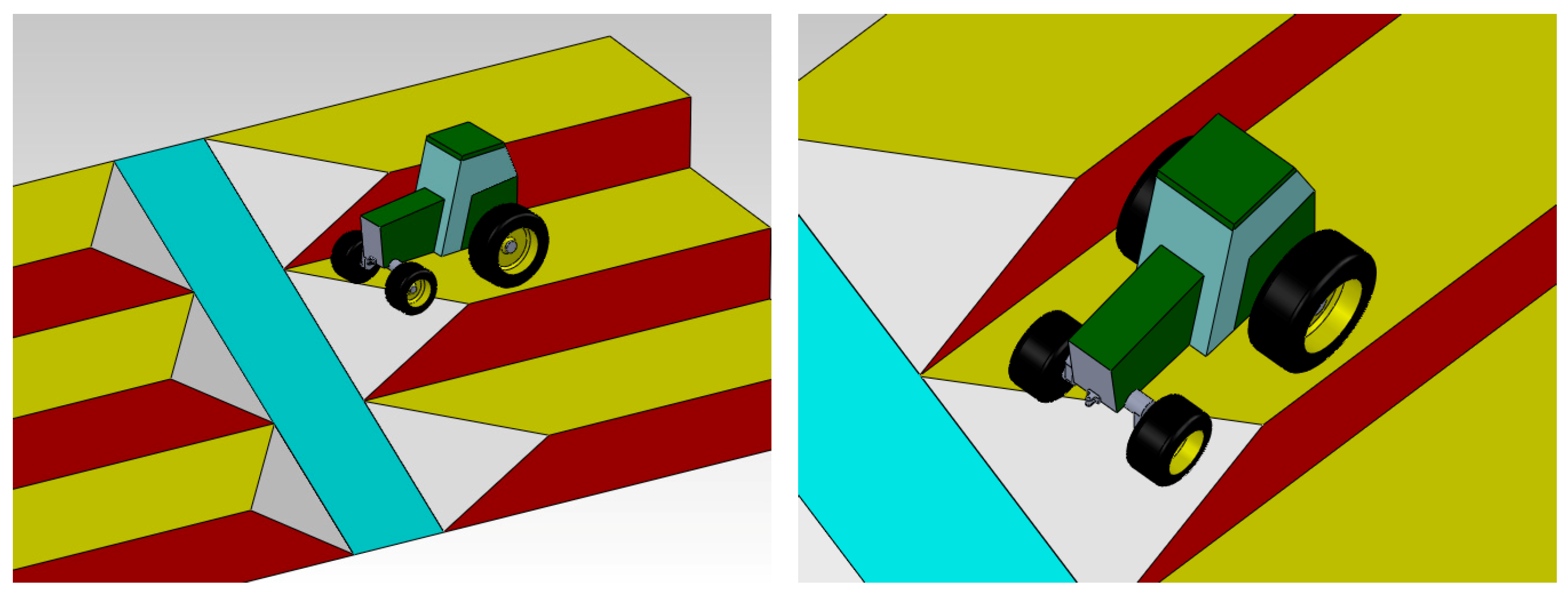
    global stability (Figure 5b); in this test the vehicle longitudinal axis and the maximum slope direction are angled (any angle between −180° and +180°);
    o
    global static load transfer (Figure 5c) and lying down on the downstream tire (real inclination of the frame) for a vehicle in the aforementioned conditions, i.e., at any angle between the vehicle longitudinal axis and the maximum slope direction of the support surface;
  • Dynamic tests of a vehicle moving along a circular path with a constant radius and at different constant speeds. The dynamic tests can assess:
    o
    global stability on a flat and tilted plane (Figure 5d); in this test the inclination of the tangent line varies at each point of this circumferential trajectory and it forms an angle comprised between -180° and +180° with the platform maximum slope direction;
    o
    global stability on a tilted plane with an edge, i.e., simulating a steering maneuver with a change in the slope (e.g., a tractor entering/exiting from an inter-row).
Some of the above-described tests are coded by international norms, especially the tests of static lateral-rollover stability [42,43]. Others are completely new and could provide much more information concerning the use and the users’ safety of agricultural machinery on sloping grounds.
According to the presented approach, it could be suitable to analyze the requirements by finding analogies and differences and, therefore, to conceptually subdivide the general test-system into several subsystems, each addressing one or more requirement.
A first analysis of the technical requirements of a possible facility leads to the following considerations:
  • The above-mentioned tests have very different requirements in spatial terms; indeed, the dynamic tests require much more space than the static tests due to the need for the vehicle to travel a whole circular path. As a practical rule-of-thumb, it is possible to calculate the test area dimensions starting from the dimensions of the width of the supporting surface of a conventional tractor. The ratio between the minor dimension of the support polygon of the machine and the minimum room of the test area can be approximated by 1 to 5. Indeed, due to the similarities in the proportions and in the maximum wheel-steering angle of all farm tractors, the minimum turning radius is usually about twice the minimum width of a tractor. In the calculation of the minimum manoeuvring space two half widths of the tractor have to be added, thus reaching the factor of 2 × 2 + 1 = 5. This ratio can be used to quantify the minimum spatial needs of the two tests after having defined the biggest machine that will be possible to test with the rig under development;
  • The required technical features, particularly with regards to the shape of the support plane, are different; the static tests require a simple and flat ‘tiltable’ plane, whereas the dynamic tests also require the creation of an edge on such plane;
  • Both types of test require a common feature of the system, i.e., the plane on which the vehicles are placed and made to travel. This must offer the possibility of being tilted with respect to the support plane of the whole system.
The requirements of the test platform in terms of indicative size, movement capability (maximum tilting angle) and applied loads (in this case: the maximum allowable mass of the agricultural machines to be tested) should be drawn from market surveys or technical databases. Indeed, with such sources of information it is possible to accurately identify the technical requirements and a possible market of reference.
Limiting agricultural machinery to tractors only, an indication of the maximum angle of inclination, which future installations must be able to guarantee to experimenters, may emerge from the analysis of the technical characteristics of existing tractors—e.g., those in OECD test reports—and if necessary limited to a maximum power or dimension class. For example, the following graphs (Figure 6) show the lateral and longitudinal stability angles of tractors tested from 1960 to 2014, calculated from the data collected during the tests according to OECD codes 1 and 2: in particular, the CoG height from the ground, the distance of the CoG from the rear axle, and the lateral shift of the CoG to the left were used [72]. The sample of tractors used for this survey (1438 tractors), although not coinciding with the entire population of tractors produced in the reference period, is still representative of world production quotas in the different years (the largest manufacturers and with more models per manufacturer are considered) and can therefore be used to make effective considerations for the present purpose.
Observing the graphs of Figure 6 reporting all the data (which are particularly useful to identify the outliers), with regards to the static overturning angles it may be noted that:
  • a test rig capable of tilting at least 50° is sufficient to test the static lateral stability of practically all the tractors produced to this day, since a maximum angle of more than 50° (more precisely, 50.1°) has been recorded for only 2 tractors out of 1438, i.e., for the 0.14% of the total;
  • a platform capable of tilting 55° is sufficient to test the static longitudinal stability of most tractors produced to this day, since a maximum angle greater than 55° has been recorded for only 21 tractors out of 1438 (1.5% of the total), none more recent than 1999; bringing the maximum angle of inclination to 57.5° would leave out only 7 tractors (0.5%).
Similar considerations can be made also for the maximum mass of the vehicles to be tested on the rig. In this case the decision can involve the dimensional class of such tractors, intentionally ignoring the largest tractors from the price lists of various manufacturers, which are anyhow also the rarest on the market. For example, considering a maximum testable mass of 6400 kg theoretically allows to test all 4WD tractors in the medium range, i.e., with a maximum power of about 110 kW/148 HP (calculated by using a mass-to-power coefficient of 60 kg kW−1). Referring to the manufacturer Fendt, models from “714” upwards would be excluded, whereas for New Holland, only the models of the “T8 series” would be excluded.
Concerning the dimensions, the ‘1:5’ rule for the calculation of the minimum turning radius can be a good starting point. If considering, for example, some general-purpose farm tractors by New Holland (the “New Holland T5 Utility” and the “New Holland T5 Autocommand”), it is easy to verify the efficacy of that rule-of-thumb, since the minimum turning radii are declared by the manufacturer (respectively 4235 mm and 4615 mm for minimum widths of 1953–2165 mm and 2288 mm). This means that the minimum manoeuvring space is 5 times the tractor width, i.e., 9765–10,825 mm and 11,440 mm. The reference dimensions could be increased up to 16 × 16 m should the test aim at circular trajectories with greater radii.
Concerning the mechanical properties of the support plane, a new test system that would improve the test systems currently used to characterize the stability of agricultural vehicles should also give a reproducible certification of the stability property of the tested vehicle. This can be obtained by creating an easily-reproducible reference soil. This principle has been adopted, for example, by OECD: in its test centers, the circuits used in the homologation of the tractors and in the tests of traction with each gear ratio are made of a specific, standardized type of concrete with a measurable surface finish, despite the fact that the tractors perform on off-road terrain. To do so, the first and simplest choice is to use a rigid support, particularly, a metal embossed/tear plate that is available worldwide and whose embossed patterns are defined by international standards. This type of support will minimize the sliding of the wheels/tracks on its surface, a phenomenon that can otherwise compromise the quantification of the stability limits of a vehicle. However, although the main needs of the system under development are different from those that have emerged, e.g., from the works by Lindemann and Voorhees [49] and by Inotsume [51] in testing the performance of a Mars exploration rover, an alternative solution that could expand the test possibilities of the system can be provided. In light of the previous considerations, any solution involving the use of loose material must be discarded, also considering its lack of practicality on a large area. Rather, it could be useful to arrange many removable panels, each approximately of 1.5 × 1.5 m size, coated with a special surface finish of standardized materials, which can be laid down according to need. The macro-roughness of these panels should be quantified in a way similar to what is done for the surfaces of mechanical components (therefore with parameters such as peak-to-valley height, profile integral mean, etc.), given the need to precisely report and declare the test conditions for reproducibility also in any other similar installation.

3.1.3. Delineation of General Features (→ Step 1.c)

Starting from these last considerations and with the aim of developing an apparatus with the ability to perform both static and dynamic tests, a system (here called ‘platform’) was developed which is equipped with a wide tilting plane. This plane should allow a vehicle, possibly with a trailer, to travel on its surface following complete circular trajectories (Figure 7), so its dimensions (16 × 16 m, as stated above) originate from the intention of performing the dynamic tests. The possibility to be tilted constitutes the first degree of freedom of the whole system (Figure 8A).
The need to generate an edge on the plane implies the need to have a second subsystem for moving part of the plane (second degree of freedom; Figure 8B). In particular, this further subsystem should have the final effect of generating an angle between two parts of the support surface (namely, half-planes or semi-platforms) and to allow the operator the possibility of having the upstream part of the support parallel to the ground or not. Looking at the spatial convenience, the best solution is placing an angulation hinge as wide as the platform width at about halfway along the plane. The two semi-platforms have therefore equal dimensions (see Section 3.2).
The creation of an edge between the two support half-planes (semi-platforms), to be overcome with the mechanical vehicle under test, is fundamental for the simulation of the exit maneuver of the same mechanical vehicle from an inter-row of a terraced slope in a controlled environment. In particular, this degree of freedom of the structure makes it possible to reproduce the dangerous load transfer that occurs at the same time as the change of support (tires in contact with the support ground; see Figure 9).
The need to perform the static test at many angles of the vehicle longitudinal axis with respect to the maximum slope direction is a slightly more complex matter. In general, this could also not require another degree of freedom (dof) of the test-equipment. In fact, a hypothetical test of this type can be performed as follows: (1) the vehicle can be moved horizontally on the plane by using its own propulsion system, (2) the plane is tilted until the vehicle reaches an incipient overturning situation, (3) the plane is moved to the horizontal position again, then (4) the vehicle is moved once more into another position on the plane and steps 1 to 3 are repeated. The need to reposition the vehicle several times during a test, however, makes such a solution not practical and urges the designer to provide a faster/easier placement of the vehicle by giving the whole system a further dof (third degree of freedom), thus requiring another sub-system, called ‘turntable’ (see Section 3.3).

3.2. Design of the Subsystem to Perform the Dynamic and Static Stability Tests (i.e., the ‘Tiltable and Angleable Platform’)

3.2.1. Conceptualization of the Mechanism(s) for Operating the System (→ Step 1.c)

Based on the expressed requirements, the design process of the platform involved the conceptualization of the kinematic mechanism(s) to operate the system. Limiting the number of the rigid links to four, it is necessary to determine how they are interfaced, i.e., how the “basic system components” perform their “fundamental interactions” [64] to define the kinematic mechanism. With that maximum number of components, there are three different possibilities (Figure 10):
  • Two links only (scheme ‘2L’ of Figure 10), the first one (AB) connected to the ground through a revolute pair (in A), the second one (BC) connected to the first link through another revolute pair (in B); both of them have an integrated surface on their top used for making a tractor travel (i.e., these two links are just the semi-platforms);
  • Three links (scheme ‘3L’ of Figure 10), one of them (AD) is a sort of support structure connected to the ground through a revolute pair (in A); when this link is inclined with respect to the ground, the two links supported by it (AB, BC) are inclined as well; the other two links have an integrated surface on their top used for making a tractor travel (i.e., these two links are the semi-platforms) and can be angled with respect to one another through two revolute pairs (in A and B) and a slider (in C);
  • Four links (scheme ‘4L’ of Figure 10), two of them (AB, DE) connected to the ground (in A, E) and forming, together with another link (BD) connected to them through revolute pairs (in B, D), an articulated parallelogram, able to keep horizontal the position of link BD whichever the inclination of AB; there is another link (BC) connected to the link AB through another revolute pair (in B); the links AB and BC have an integrated surface on their top used for making a tractor travel (i.e., these two links are the semi-platforms).
As the test rig will have two degrees of freedom, the final project will have (at least) two actuators or rather, two pairs of actuators due to the spatial extension of the installation. Indeed, as a general principle, in the development of a structure, each dof of the system (i.e., considered an independent movement) should correspond to an actuator of some kind.
The test configuration of the system is given by fixing the relative positions of the two semi-platforms (AB, BC in Figure 10, Figure 11, Figure 12 and Figure 13) for the duration of a test, and this can be controlled by acting on:
  • the position of the free end-points of each link (B, C, D) in terms of relative distance from a reference (ground, or other link; see Figure 11, schemes 2L.a–d, Figure 12 schemes 3L.a–d, Figure 13 schemes 4L.a–d), obtained by supporting them (e.g., with linear actuators), and/or
  • the inclination of these links (AB, BC, AD, DE) related to a reference (ground, other link; see Figure 11, schemes 2L.b–e, Figure 12 schemes 3L.b–f Figure 13 schemes 4L.b–f), obtained by blocking the revolute pairs (e.g., with a rotary actuator or a linear actuator, connected to the two articulated links so close to the articulation hinge as to act as a rotary actuator).
The schemes presented in Figure 11, Figure 12 and Figure 13 report each of the solutions described above. Moreover, in some of these solutions (Figure 12) there is also an additional link (AD), namely the ‘platform support-frame’, which is an intermediate structure supporting both semi-platforms and responsible for their global inclination. The additional links of Figure 13 which form an articulated parallelogram have been introduced to have a link (BD) connected to the same revolute pair of link BC (the upper semi-platform) and to keep the horizontal position at every inclination of AB, thus constituting a close reference for the inclination of BC.
In schemes 2L.b–e, 3L.b–f, 4L.b–f there is at least one component that is controlled in its inclination and one (or none) supported only in a single point. By referring to the schematics of beams, the so-called ‘unsupported length’ is equal to a semi-platform length in scheme 2L.b, 4L.b, 4L.e–f, but can reach the entire extension of the platform as the sum of the two semi-platforms’ lengths (2L.c-e, 3L.c-f), or it can be equal to the additional component length (3L.b, 3L.e, 3L.f) or articulated parallelogram side (4L.c–f). In particular, in schemes 2L.b, 2L.e, 3L.b, 3L.e–f, 4L.b, and 4L.e–f there are components that behave like a cantilever beam. Therefore, all these solutions are more likely to suffer from problems of elastic oscillations and perhaps even resonance caused by the vehicle travelling on the semi-platforms, as described by different Euler buckling modes. For the described reasons, solutions acting on the position of the end points of the links (2L.a, 3L.a, 4L.a) should be preferred.
In schemes 2L.a, 2L.d and 4L.a–f, if the two semi-platforms have to be inclined whilst remaining aligned, points A, B, and C should be aligned. This means that both the actuators (whichever they are) have to be operated simultaneously and with proper synchronization. This adds a further (mechanical) complication to the operation of the platform, underlining also that the dofs of global inclination and angulation are not fully independent, and that the actuator controlling the position of B acts on the inclination of both semi-platforms. According to the general design principles enunciated before (functional analysis and functional decomposition), it is convenient to keep the functions of overall inclination and angulation of the two semi-platforms separate, opting for a solution that provides for a separate actuation systems. Indeed, the scheme 3L.a does not suffer from the alignment problems of AB and BC thanks to the presence of the support frame AD.
The schemes of Figure 11 and Figure 12 have another problem: if the inclination of the lower semi-platform AB (or rather, the vertical position of B) is changed, the inclination of the upper semi-platform BC is also changed. Given the impossibility of independently controlling the inclination of the two semi-platforms with these schemes except by applying more complex schemes (e.g., using an articulated parallelogram as in Figure 13), and considering the advantages of the support frame with the aim of avoiding too much long ‘unsupported length’, and not increasing the complexity of the linkage, scheme 3L.a should be considered as the most suitable. In this solution, the overall inclination of the two semi-platforms, when aligned, is given by acting on the intermediate support structure; the angle between the two semi-platforms is obtained by acting on a semi-platform only.

3.2.2. Illustration of the Different Possibilities for Implementing the Global Inclination Mechanism (→ Step 1.c)

Taking into account the main tilting movement of the platform support-frame—i.e., a rigid rotation around a point fixed in the space (A)—it is also possible to envisage several solutions that kinematically have the same effect (in this case: a rotation). The conceptual process is schematized in the following Figure 14.
The two translational components vx and vy in any point of the rigid body approximating the support-frame of the platform are not mutually-independent, being the body constrained by a revolute pair and therefore having only one dof (i.e., the rotation on the xy plane). This results in the possibility of obtaining a rotation for this body by applying only a component of v (via a linear actuator) and leaving the second component out, for example lifting of the end-point B of the platform support-frame (Figure 15):
  • using a hydraulic jack: the displacement of a certain lubricant volume within the expansion chambers of a cylinder causes the displacement of a piston and, hence, the elongation of the jack; in this manner, only the vertical component of the displacement vector of the apex is imposed; this solution is extensively described in this document;
  • using a winch and a cable: the winch rotation pulls the cable connected to it and, by means of a fixed pulley placed on top of a structure, the vertical component of the displacement vector of the end-point is imposed;
  • via a nut and a threaded bar: the rotation of the threaded bar causes a translation of the nut which engages on it; through a slider connected to the nut, the vertical component of the displacement vector of the apex is imposed.
Note that, according to the rigid movement of the platform around the articulation hinge, the end-point B of the platform has a horizontal translation toward the hinge as a result of the vertical lifting of the same point B; therefore, all the illustrated solutions have the capability of complying with this movement (all the above-described actuators generate a vertical thrust, freeing any horizontal movement of B).
It is also possible to evaluate some alternative configurations in which the hinging point A is released on the horizontal plane, and hence, in which the trajectory of the end point B is straight and vertical. In this way, the horizontal translation of the end-point B of the platform toward the direction of the hinge, which can be observed with the first solutions (Figure 15), is instead attributed to the other end of the platform, i.e., to the support point A (according to the kinematic inversion principle, see Section 3.4; Figure 16). Therefore, the resulting movement of the tilting platform becomes that of rotation (around the point A, not fixed in space) and translation (horizontal shift toward the end-point B).
Another possibility to move the platform is represented by acting on the other component of the motion of the end-point B of the tilting platform (horizontal translation), with adequate thrust systems, thus causing the rotation of the same platform as the only kinematically-permissible motion. For example, this could be done through a horizontal hydraulic jack or by a threaded bar and a nut, both acting on a special thrust structure shaped as a vertical rail (Figure 17). The rail allows the vertical translation (in particular, upward) of the point B under the effect of a horizontal thrust.

3.2.3. Preliminary Analysis and Selection of the Different Implementing Possibilities for the Inclination Mechanism (→ Step 1.d)

Observing the line of action of the adopted generic linear actuator (hence, the dynamics of the lifting mechanism), the above-presented solutions can be grouped as follows:
  • solutions providing for the lifting of the platform support-frame by using an actuator acting vertically (Figure 15 and Figure 16);
  • solutions providing for the lifting of the platform frame by using an actuator acting horizontally and using a movable vertical-rail (Figure 17).
Thanks to this classification, it is possible to formulate a several comments that are valid for more than one solution. In particular, in order to analyze the feasibility and thus the advantage or not of proceeding with the implementation of one of the presented solutions/schemes, it is necessary to quantitatively analyze the components of the vector apical displacement. Indeed, it is possible to observe that the vertical component of the vector, related to the trigonometric factor ‘cosine’, is quantitatively predominant on the horizontal component, which is instead related to the trigonometric factor ‘sine’, up to a 45°-angle. This means that, to achieve the same inclination of the platform (or the same angular speed), the vertical component of the vector displacement (or speed) will always be much greater than the horizontal component, resulting in a more favorable ratio of force multiplication.
Notice also that, in a completely horizontal position for the platform, the mechanism is located in a so-called ‘kinematic singularity’: the alignment of point A and B on the horizontal axis, in fact, represents an equilibrium position of the system; any thrust applied at the point B and direct toward A causes a compression of the platform structure, a stress of the articulation hinge in A and might not result in a rotation of the platform around A. Also, since the trigonometric factor ‘sine’ is zero (or near zero) in this configuration, the ratio between the horizontal thrust-force and the vertical force causing the start of the platform lifting (i.e., its inclination) tends towards infinity, hence it is extremely unfavorable for a possible horizontal component in correspondence to very small angles.
Albeit potentially leading to the same result from a kinematic point of view, the presented solutions are not equivalent from the dynamic point of view. All the schemes in which the platform support-frame is lifted by using an actuator acting vertically are more favorable as regards the application of a force to the structure and, therefore, should be given preference for implementation.
A second important classification can be defined by the type of motion followed by the platform during its lifting (hence, by the kinematic scheme); according to this criterion, the above-presented solutions can be divided into two groups:
  • solutions providing for the inclination of the platform frame with a pure-rotation movement (Figure 15 and Figure 17);
  • solutions providing for the inclination of the platform frame with a rotatory-translational movement (Figure 16).
In case of adoption of an inclination-scheme providing a rotatory-translational movement, there are important implications to be considered. In particular, there is the need to create some guides to make the platform slide in correspondence to its pivot point A (Figure 16). From a mechanical point of view the use of wheels and ball-bearings could be an interesting solution to limit the friction in a part of the frame that directly supports approximately half of the payload and of the weight of the structure. Moreover, the presence of vertical sliders at the other end of the platforms would constitute a further complication to the system, as this would be a vertical structure needed for the platform functioning, parallel to the actuation system and acting on the same direction.
Other considerations can be done on the actuators, i.e., the technical systems for generating the thrust force (hydraulic jack, or threaded rod and nut) or the traction force (winch and cable) needed to operate the system. For example, on one hand, the hydraulic jack and the threaded rod can suffer from possible limitations in their maximum extension to avoid the occurrence of the buckling phenomenon. On the other hand, the cable pulled by the winch to lift the platform has an intrinsic elasticity (due to the cable thickness and extension) higher than the other above-cited actuators. This could cause unwanted oscillations of the suspended body (the platform) during the execution of the dynamic tests. Although this solution can have some advantages (e.g., no limitation to the lifting displacement), other systems could be required for fixing the position of the platform when tilted. By doing so, the winch-and-cable system should be used only for moving the platform.
A tool that can be used for the comparative evaluation of the many solutions identified in the previous phase is the table proposed below (Table 2): it summarizes all the solutions illustrated here briefly stating their advantages and disadvantages (‘pros’ and ‘cons’) in relation to a set of characteristics (similarly to what suggested by Pugh about the concept screening, [73]). The different solutions for each subsystem are therefore evaluated on a comparative basis that considers the listed pros and cons.
On the basis of the advantages and disadvantages listed in Table 2, it is possible to note that one of the enumerated solutions can be preferable to the others: a fixed articulation placed at point A, the lifting of the apex of the ‘tiltable’ platform B obtained by means of thrust mechanism acting with a vertical component only, specifically a hydraulic jack. At this stage of the design-process, it is therefore not necessary to use other more advanced methods of decision-making such as multi-criteria analysis, which still would not eliminate bias, uncertainties, subjectivity, and qualitativeness of the solutions [74,75]. Rather, in the following phases (phase 2 ‘detailed design’; phase 3 ‘manufacturing, construction, installation and inspection’; see Section 2), these advanced methods could be very useful to evaluate many other aspects simultaneously. For example: the ease of finding the required components on the market, the estimated ease of manufacturing (if the manufacturing is performed by the same company that is conceiving the final design), the estimated resistance of the structure, the estimated energy absorptions of actuators. However, in the absence of historical data on similar projects, the accuracy of the estimation and the capability of evaluation of these methods decrease significantly.

3.2.4. Proposal of an Actuation Mechanism (→ Step 1.d)

Taking into account all the considerations presented herein, the following solutions were selected:
  • The operation of the platform is performed by hydraulic linear actuators. These are particularly suitable in such cases as the present because: (1) they are able to develop large thrust forces, (2) they have a high flexibility of positioning thanks to the physical separation among the power-generation system (for pressurizing the operating fluid), the control system (typically: a control panel and an electro-hydraulic distributor) and the power-using system (i.e., the actuator, indicated as ‘hydraulic jack’);
  • The overall inclination of the platform is provided by operating an actuator against the platform support-frame [76], articulated at one end of it with the base. The reference scheme is a triangular pattern with a variable-length link (i.e., the linear actuator; Figure 18, I.a–I.b). In the final project, if the system will require a lighter structure with the same overall structural resistance (capability to support agricultural machines), the indicated kinematic scheme could possibly be replicated by placing two actuators per side which operate simultaneously and in parallel (i.e., at the brim and at the middle of the main frame, Figure 18, I.a–I.b);
  • The angle between the two semi-platforms is obtained by acting on one semi-platform only. The second semi-platform is inclined as the result of the position taken by the first one (Figure 18, A.a–A.b). The kinematic scheme for the lower semi-platform which is driving the entire angling mechanism is again a triangle with a variable-length side. Instead, the complete angulation mechanism of the two semi-platforms is similar to a centered crank-mechanism. For practical reasons, i.e., to make it easier for a vehicle to get on and off the platform, the articulated joints of the lower semi-platform and of the main structure of the platform are adjacent.
Consequently, the two kinematic mechanisms described before are superimposed as reported in Figure 19.
Finally, if after a first dimensioning of the system and the choice of actuators from a catalogue ( Steps 1.d, 1.e) the length of a single, fully-extended hydraulic jack were not sufficient to provide the maximum desired inclination, other alternative solutions should be considered (Figure 20):
  • (AS1.) Shift of the position of cylinders toward the hinges. The shifting distance is however limited by the need to not interfere with the circular paths of the vehicles under test and with the coupling points of the secondary actuators. Unfortunately, by doing so the ‘tiltable’ structure will be partly cantilevered with respect to the position of the connection points of the primary actuators;
  • (AS2.) Juxtaposition of two equal jacks, in a series-parallel configuration (only if the global length is far from buckling), possibly in combination with the previous solution;
  • (AS3.) Creation of a kinematic mechanism (with one dof) that multiplies the elongation of a single actuator to obtain the complete lifting of the platform. The creation of a concave articulated quadrangle is proposed as the best solution in this case. The dimensions of the folded components and their possible interference with the secondary actuators must be considered in the design of the modified structure. Particular consideration should be awarded to the coupling points and to the dome height.
Also, in this case, as previously done for the solutions concerning the global inclination mechanism, it is possible to synoptically evaluate the advantages and disadvantages of the proposed solutions to increase the maximum inclination reachable by the support plane (Table 3).
Considering the illustrated advantages and disadvantages, the preferable solution is to shift the coupling points of the primary actuators toward the inclination hinges.

3.3. Design of the Subsystem to Perform the Global Static Stability Tests (i.e., the ‘Turntable’)

3.3.1. Conceptualization of the Mechanism for Operating the System and Illustration of a Possibility for Implementing the Mechanism (→ Step 1.c)

If, as frequently occurs, the attention of a designer of test equipment is focused only on the vehicle to be tested or on the test system but not on both, the creativity of the designer could be limited, thus bringing to conventional solutions only, precisely as observed by Altshuller [77]. As regards the static stability tests (lateral stability, longitudinal stability, global stability, global load transfer; see Section 3.1.2), for example, the designer could be led to regard the object of the test (here: an agricultural machine) as completely still/immobile on a piece of equipment. All the creative efforts are directed toward the test rig, and particular attention will be diverted to conferring the test rig with all the degrees of freedom required to perform the tests on the vehicle. This way of thinking has brought to the conceptualization of the first ‘tiltable’ platforms (conventional ‘tiltable’ platforms), having a single dof necessary to tilt the platform and induce the overturning of the vehicle placed above these, as in the system developed by Gravalos et al. [3]. A possible evolution of this system would be to equip the test rig with a second possibility of inclination as proposed by Zhao et al. [46] to test the stability of a machine also in a direction perpendicular to the first without moving the test subject. This second possibility of inclination could constitute a real second dof of the system as well as not, in the sense that:
  • The second inclination could be alternative to the first (Figure 21), as visible, for example, on dump-trailers having two possibilities of tilting (in these trailers, the body is inclined in one direction or in the other by blocking/unblocking the articulation hinges of interest); in this case, the system would have only one dof at a time (i.e., the inclination), which is activated in two different (perpendicular) directions, one at a time (see Figure 21a,b); two hinges are a revolute pair that can be disassembled (A, C in Figure 21), the third one (B in Figure 21) is instead a ball joint; it is interesting to note that the system can be operated by a single linear actuator, which acts on the only vertex that does not have a hinge (D in Figure 21);
  • The second dof could be concurrent to the first dof and constitute a true second dof of the considered system (Figure 22), thus providing tilting directions comprised between the two main directions (i.e., the directions parallel to the longitudinal and transversal axes of the vehicle in test), thus spanning an angle of 90°; in this case, the system implementing the contemporary double-tilt has two revolute pairs and a ball joint like in the other architecture of Figure 21, but it could be even very complicated; indeed, it is necessary to have an additional, intermediate frame that is the support structure for the second inclination mechanism that operates the plane supporting the vehicle under test.
Instead, by adopting a holistic point of view, other possibilities can be explored (→ step 1.d) and the final result of the conceptualization process could be even more interesting than the above-described solutions. In this case, for example, adopting the kinematic inversion principle (see Section 3.4), instead of having a stationary vehicle placed on a device capable of performing more or less complex movements (tilting platform with at least two degrees of freedom, corresponding to two hinges), the following solution could be preferable (Figure 23):
  • the support structure has only one dof (i.e., the possibility of inclining the supporting structure in a unique direction, as in the conventional test rigs for investigating the static lateral overturning angle);
  • the vehicle is given a second dof or, rather, this second dof is enacted by the part of the support immediately below the vehicle; this could be achieved by positioning the vehicle on a rotating platform (‘turntable’) included within the ‘tiltable’ structure.

3.3.2. Preliminary Analysis and Selection of the Different Implementing Possibilities for the Inclination Mechanism (→ Step 1.d)

Similarly to what has been done for the global inclination mechanism, the pros-and-cons of each above-illustrated solution to perform the global static stability tests are collected in the following Table 4 for proper evaluation.

3.3.3. Proposal of an Actuation Mechanism (→ Step 1.d)

Thanks to the synoptic table above, the following solution has been outlined: the system to perform the global static stability tests (and hence all other stability tests listed in Section 3.1.2) is a subsystem of the main test rig thought to test the stability of a motionless vehicle (global static stability), and it is configured as a rotating platform (‘turntable’). Indeed, combining the tilting angle given by the supporting structure operated by another subsystem (defined in the previous paragraphs; see Section 3.2), with the angular position of the turntable, the longitudinal axis of a vehicle can be positioned at different angles as regards the maximum slope direction. The turntable is an integral part of the platform here described and it can be placed in the lower semi-platform. The turntable surface (above which the vehicle in test is placed) is perfectly aligned with the surface of the lower semi-platform and should be made of the same material (Figure 24, top). When the turntable is not in use for performing any static stability test, it should be locked so that any vehicle performing a dynamic test on the whole extension of the platform can travel also on the turntable surface along circular trajectories (Figure 25). In the same way, if during the dynamic tests there is a need to change the surface properties of the platform by covering it with the removable panels described in Section 3.1.2, it should also be possible to fix the panels onto the turntable.
The approximate sizing of the turntable diameter can be performed only after establishing the maximum size of the tractor that can be tested with this system. Since all four wheels of the vehicle should be placed inside the rotation circle of the turntable, the Pythagoras theorem can be applied to the measures of the tractor wheelbase and maximum width, assuming therefore that the geometric center of the tractor is close to the platform center. For example, considering only the New Holland tractors that are currently produced, the diameter should be at least 3174 mm (excluding the models of the T8 series, which are very large) or 4362 mm if including the T8 series. The wide dimensions of the tiltable support surface of the platform (each semi-platform has a size of 8 × 16 m), the values just found are not a problem and the diameter can be chosen to be of 5000 mm.
In order to measure the weight loaded on each tire during a stability test and quantify the load transfer due to the inclination, the surface of the turntable is divided into four independent quadrants, one per each tire (Figure 24, bottom right; Figure 26). Each quadrant is placed on a load-cell that can measure the force exchanged with the supporting structure below, as in the systems realized by Gravalos et al. [3] and by Wang et al. [48], with the important difference that, in the present case, the turntable and its weighing quadrants can rotate around a vertical axis (Figure 27). The quadrants and the load cells are fixed to an underlying rotating support structure. Although the load cells are placed at a fixed distance from each other (at the vertices of a square and at a distance of 1060 mm from the center, i.e., at the geometric centroid of each quadrant), any vehicle able to position its wheels on the quadrants can be tested.
Therefore, a global static stability test is performed as follows: once a vehicle is positioned on top of the turntable with a tire on each quadrant, the platform performs a complete rotation around its central vertical axis (Figure 28) with a relatively slow speed (e.g., 0.026 rad s−1: a full rotation will be completed in about 4 min) and then returns to its initial position. During the platform rotation, the forces supported by each quadrant will be recorded continuously. A null force recorded by a load cell indicates a situation of incipient overturning for the vehicle. Therefore, the same device allows the investigation of the global static stability as well as the load transfer and, with some inclination sensors, also the lying-down effect of a vehicle on the downstream tires.

3.4. Remarks to the Presented Work from the Design Point of View

The design approach described in this work has benefitted from several theoretical and numerical conceptual tools from leading mechanical engineering and design disciplines, with particular reference to: design of assemblies and systems modeling, mechanical design and structural mechanics, dynamic systems modeling and simulation, hydraulics.
Two design principles, which can be inferred from the present case study, have become particularly advantageous. They mirror design knowledge from two powerful, although partially conflicting, design theories: Axiomatic Design and TRIZ [78,79]:
  • Functional analysis and functional decomposition—In order to enhance control, it may be useful to analyze the different functions that a system can perform, to create the functional components composing the final system, and to assign each of these components a single operation [60,61], as done for the ‘tiltable’ and ‘angleable’ platform. Despite a higher initial conceptual effort, the complexity of the whole system can be more easily managed and the proposed technical solutions will result simpler. Moreover, it can be convenient from a kinematic point of view also to consider decomposing composite motions into simpler motions, each performed by a single subsystem, somehow reflecting Axiomatic Design indications [80,81]. Every subsystem is therefore responsible for a single component of the global motion due to the principle of ‘superposition of independent motions’ or of ‘independence of simultaneous actions’. From an engineering point of view, good practice stands in separating all elementary motions (translational or rotational) achievable by linear or rotary actuators properly synchronized in order to obtain the desired final motion. Finally, in some cases it could be also convenient to generate a rotational motion by supplying the instant linear components deriving from the vector decomposition of tangential velocity. This study shows how the same principle was applied also to elementary movements (e.g., a rotational motion responsible for the inclination of the platform), by conceiving technical systems acting on the instantaneous Cartesian components of the displacement vector at each point of the trajectory.
  • Kinematic inversion—some solutions may be simplified if the designer is able to embrace a system perspective, as suggested by TRIZ [77] and more explicitly by the System Operator [82] or the Trends of Engineering Systems Evolution [83]. This means that some constraints can be redefined or some degrees of freedom attributed to systems different from conventional ones. As exemplified in the paragraphs above, with specific regard to the turntable, this principle can also be applied to the design of the equipment for static tests by changing some attributes of the vehicle under test, e.g., its immobility with respect to a reference system fixed to the test apparatus (Figure 21 and following).

4. Conclusions

A novel facility for testing the static and dynamic stability of agricultural machinery has been conceptualized and studied, and its layout has been designed by means of the design process described herein.
The illustrated approach draws on the one normally used for the development of an industrial product but takes into account the differences pertinent to the specific case under consideration. Indeed, the design of a test apparatus is different from that of an industrial product because it is more focused on the technical characteristics that the test apparatus must be able to investigate. The effort of conceptualization is therefore greater because the conceptualization phase necessarily requires an extra step. Specifically, the whole design process originated from the necessity of a test rig to make vehicles experience situations as close as possible to real ones. The development of this system began from macro-requisites and reached the definition of the minimum technical requirements of each subsystem, gradually focusing on smaller and smaller parts and increasing the level of detail. Two principles demonstrated particular advantage in the design process: the functional analysis and functional decomposition, and the kinematic inversion. The outputs of this design process are several schemes and CAD-drawings concerning the system and the solutions to be adopted on it. These outputs can be used to guide the action of a designer involved in the detailed design of the system.
From a practical point of view, the relevance of this study is demonstrated by the effectiveness and ease of application of the presented methodology. The acknowledged criteria that are part of it led to the development of an enhanced test rig configuration. The approach proposed here is a key to interpreting the needs of the several agents usually involved in a product-development process, especially when it involves players with different backgrounds. Indeed, the needs of the client should be interpreted as technical features and/or final requirements of the test facility to be developed. The client only sums up the technical requirements that a hypothetical test structure should be able to test, but without any idea on how this test structure should be developed. A structural engineer is then able to properly dimension a structure, yet does not necessarily have an idea about the final tasks that the product should perform and will require a set configuration of the test facility on which to work to define the final design and the construction details. Between client and structural engineer, an interface person filling the gap must be able to listen to the committers, interpret their needs [67], and translate them into technical requirements of a test structure for the engineer who can, at this point, play his role in the most effective way. This interface role can be guided by the procedure outlined in the present paper. Therefore, the methodology and its conceptual tools facilitated the development of the concept for a test rig, and served as a tool to ease the communication between the players involved in the product development, to overcome the barriers between those who identify the requirements, those who must develop the technical solutions and any other experts in the field.
The proposed equipment is configured as a mechanical installation with three degrees of freedom: it presents a wide ‘tiltable’ plane with a central articulation hinge, specifically thought for performing dynamic tests (travelling of circular paths, possibly with a sharp change of the slope in the middle thanks to the articulation hinge) and operated by hydraulic jacks. An additional subsystem configured as a rotating platform (‘turntable’) can test the stability of motionless vehicles without the need for repositioning. Thanks to its features, the presented test rig allows the reproduction of scenarios related to an agricultural machine operating on a sloping ground in a controlled environment, thus overcoming the limitations of current test systems for overturning. In particular:
  • the test rig can incline the plane on which the machine is placed, thus making the machine experience many situations of static overturning at different angles with respect to the maximum slope condition, especially due to the turntable;
  • the same supporting plane is wide enough to allow the machine to travel across it along circular trajectories, thereby allowing experimenters to evaluate the dynamic contribution to the rollover (centrifugal force);
  • the same supporting plane is subdivided into two parts which can take up different inclinations, thus simulating the scenario of a tractor driving out from an inter-row (terracing) of a field placed on a hillside;
  • the supporting plane is made of a rigid non-slip standardized surface, i.e., a metal embossed/tear plate, to maximize the reproducibility of results, but to which there is also the possibility to fix a number of removable panels of well-identified characteristics of surface roughness to expand the test possibilities of the system.
Since we are convinced that this installation can greatly contribute to broaden the knowledge of the static and dynamic behavior of agricultural machines, thus allowing the adoption of solutions that increase the safety, the intention of the authors is to use the illustrated solution as a starting point for the realization of the test rig in the very near future The future steps towards such aim include the analysis of the proposed conceptual design by an engineering studio, the estimation of costs, and possible further variations of the design to make it feasible.

Author Contributions

The authors contributed to the study reported in this article as follows. Conceptualization, M.B.; Methodology, M.B.; Software, M.B.; Validation, M.B.; Formal analysis, M.B.; Investigation, M.B.; Resources, M.B.; Data curation, M.B.; Writing—original draft preparation, M.B.; Writing—review and editing, M.B.; Visualization, M.B.; Supervision, F.M.; Project administration, M.B. and F.M.; Funding acquisition, F.M.

Funding

This work was supported by the Open Access Publishing Fund of the Free University of Bozen/Bolzano.

Conflicts of Interest

The authors declare no conflict of interest. The funders had no role in the design of the study, in the collection, analyses, or interpretation of data, in the writing of the manuscript, or in the decision to publish the results.

References

  1. Mazzetto, F.; Bietresato, M.; Vidoni, R. Development of a dynamic stability simulator for articulated and conventional tractors useful for real-time safety devices. Appl. Mech. Mater. 2013, 394, 546–553. [Google Scholar] [CrossRef]
  2. Hunter, A.G.M. A review of research into machine stability on slopes. Saf. Sci. 1993, 16, 325–339. [Google Scholar] [CrossRef]
  3. Gravalos, I.; Gialamas, T.; Loutridis, S.; Moshou, D.; Kateris, D.; Xyradakis, P.; Tsiropoulos, Z. An experimental study on the impact of the rear track width on the stability of agricultural tractors using a test bench. J. Terramech. 2011, 48, 319–323. [Google Scholar] [CrossRef]
  4. Previati, G.; Gobbi, M.; Mastinu, G. Mathematical models for farm tractor rollover prediction. Int. J. Veh. Des. 2014, 64, 280–303. [Google Scholar] [CrossRef]
  5. Vidoni, R.; Bietresato, M.; Gasparetto, A.; Mazzetto, F. Evaluation and stability comparison of different vehicle configurations for robotic agricultural operations on side-slopes. Biosyst. Eng. 2015, 129, 197–211. [Google Scholar] [CrossRef]
  6. Mazzetto, F.; Bietresato, M.; Gasparetto, A.; Vidoni, R. Simulated stability tests of a small articulated tractor designed for extreme-sloped vineyards. J. Agric. Eng. 2013, 44, 663–668. [Google Scholar] [CrossRef]
  7. Spencer, H.B. Stability and control of two-wheel drive tractors and machinery on sloping ground. J. Agric. Eng. Res. 1978, 23, 169–188. [Google Scholar] [CrossRef]
  8. Sun, D.; Chen, D.; Wang, S.; Wang, X. A Dynamic Instability Detection and Prediction System for High Clearance Tractor. IFAC–PapersOnLine 2016, 49, 50–54. [Google Scholar] [CrossRef]
  9. Liu, J.; Ayers, P.D. Off-road Vehicle Rollover and Field Testing of Stability Index. J. Agric. Saf. Health 1999, 5, 59–72. [Google Scholar] [CrossRef]
  10. National Safety Council. Accident Facts; National Safety Council: Chicago, IL, USA, 2001. [Google Scholar]
  11. Goldenhar, L.M.; Schulte, P.A. Methodological issues for intervention research in occupational health and safety. Am. J. Ind. Med. 1996, 29, 289–294. [Google Scholar] [CrossRef]
  12. Yoder, A.M.; Murphy, D.J. Evaluation of the Farm and Agricultural Injury Classification Code and follow-up questionnaire. J. Agric. Saf. Health 2000, 6, 71–80. [Google Scholar] [CrossRef] [PubMed]
  13. Hallman, E.M.; Pollock, J. Learning from Tragedy: How to Effectively Perform and Utilize an Injury Investigation—Paper No. 997045; ASAE: Washington, DC, USA, 1999. [Google Scholar]
  14. Cecchini, M.; Cossio, F.; Marucci, A.; Monarca, D.; Colantoni, A.; Petrelli, M.; Allegrini, E. Survey on the status of enforcement of European directives on health and safety at work in some Italian farms. J. Food Agric. Environ. 2013, 11, 595–600. [Google Scholar]
  15. Váliková, V.; Rédl, J.; Antl, J. Analysis of accidents rate of agricultural off-road vehicles. J. Cent. Eur. Agric. 2013, 14, 1303–1316. [Google Scholar] [CrossRef]
  16. Mashadi, B.; Nasrolahi, H. Automatic control of a modified tractor to work on steep side slopes. J. Terramech. 2009, 46, 299–311. [Google Scholar] [CrossRef]
  17. Murphy, D.J.; Kiernan, N.E.; Chapman, L.J. An occupational health and safety intervention research agenda for production agriculture: Does safety education work? Am. J. Ind. Med. 1996, 29, 392–396. [Google Scholar] [CrossRef]
  18. Pascuzzi, S. A multibody approach applied to the study of driver injuries due to a narrow-track wheeled tractor rollover. J. Agric. Eng. 2015, 46, 105. [Google Scholar] [CrossRef] [Green Version]
  19. Longo, D.; Pennisi, A.; Bonsignore, R.; Schillaci, G.; Muscato, G. A small autonomous electrical vehicle as partner for heroic viticulture. Acta Hortic. 2013, 978, 391–398. [Google Scholar] [CrossRef]
  20. Bekker, M.G. Theory of Land Locomotion: The Mechanics of Vehicle Mobility; The University of Michigan Press: Ann Arbor, MI, USA, 1956; ISBN 9780472750207. [Google Scholar]
  21. Peters, S.C.; Iagnemma, K. An analysis of rollover stability measurement for high-speed mobile robots. In Proceedings of the 2006 IEEE International Conference on Robotics and Automation, Orlando, FL, USA, 15–19 May 2006; pp. 3711–3716. [Google Scholar]
  22. Spencer, H.B.; Owen, G.M.; Glasbey, C.A. On-site measurement of the stability of agricultural machines. J. Agric. Eng. Res. 1985, 31, 81–91. [Google Scholar] [CrossRef]
  23. Bietresato, M.; Carabin, G.; Vidoni, R.; Mazzetto, F.; Gasparetto, A. A Parametric Approach for Evaluating the Stability of Agricultural Tractors Using Implements during Side-Slope Activities. Contemp. Eng. Sci. 2015, 8, 1289–1309. [Google Scholar] [CrossRef]
  24. Yisa, M.G.; Terao, H.; Noguchi, N.; Kubota, M. Stability criteria for tractor-implement operation on slopes. J. Terramech. 1998, 35, 1–19. [Google Scholar] [CrossRef]
  25. Abu-Hamdeh, N.H.; Al-Jalil, H.F. Computer simulation of stability and control of tractor-trailed implement combinations under different operating conditions. Bragantia 2004, 63, 149–162. [Google Scholar] [CrossRef]
  26. Stockton, A.D.; O’Neill, D.H.; Hampson, C.J. Methods for Optimising the Effectiveness of Roll-Over Protective Systems–CRR 425/200; HSE: Bedford, UK, 2002.
  27. Lin, C.C.; Peng, H.; Grizzle, J.W.; Kang, J.M. Power management strategy for a parallel hybrid electric truck. IEEE Trans. Control Syst. Technol. 2003, 11, 839–849. [Google Scholar]
  28. Huang, R.; Zhan, J.; Wu, J. Effect of Differential Modeling on Handling and Stability. In Proceedings of the FISITA 2012 World Automotive Congress; SAE–China, FISITA: Beijing, China, 2012; Volume 198, pp. 441–448. [Google Scholar]
  29. Silleli, H.; Dayıoğlu, M.A.; Gültekin, A.; Ekmekçi, K.; Yıldız, M.A.; Akay, E.; Saranlı, G. Anchor mechanism to increase the operator clearance zone on narrow-track wheeled agricultural tractors: Prototype and first tests. Biosyst. Eng. 2007, 97, 153–161. [Google Scholar] [CrossRef]
  30. Solmaz, S.; Akar, M.; Shorten, R.; Kalkkuhl, J. Real-time multiple-model estimation of centre of gravity position in automotive vehicles. Veh. Syst. Dyn. 2008, 46, 763–788. [Google Scholar] [CrossRef]
  31. Kise, M.; Zhang, Q. Sensor-in-the-loop tractor stability control: Look-ahead attitude prediction and field tests. Comput. Electron. Agric. 2006, 52, 107–118. [Google Scholar] [CrossRef]
  32. Chen, Y.; Hereid, A.; Peng, H.; Grizzle, J. Enhancing the performance of a safe controller via supervised learning for truck lateral control. J. Dyn. Syst. Meas. Control 2019, 141, 101005. [Google Scholar] [CrossRef]
  33. Dahmani, H.; Chadli, M.; Rabhi, A.; El Hajjaji, A. Road curvature estimation for vehicle lane departure detection using a robust Takagi–Sugeno fuzzy observer. Veh. Syst. Dyn. 2013, 51, 581–599. [Google Scholar] [CrossRef]
  34. Oke, P.; Nguang, S.K.; Qu, W. Robust H∞ Output-Feedback Yaw Control for Vehicles with Differential Steering. J. Control Sci. Eng. 2018, 2018, 7129240. [Google Scholar] [CrossRef]
  35. Demšar, I.; Bernik, R.; Duhovnik, J. A mathematical model and numerical simulation of the static stability of a tractor. Agric. Conspec. Sci. 2012, 77, 143–150. [Google Scholar]
  36. Baker, V.; Guzzomi, A.L. A model and comparison of 4-wheel-drive fixed-chassis tractor rollover during Phase I. Biosyst. Eng. 2013, 116, 179–189. [Google Scholar] [CrossRef]
  37. Guzzomi, A.L. A revised kineto-static model for Phase I tractor rollover. Biosyst. Eng. 2012, 113, 65–75. [Google Scholar] [CrossRef]
  38. Ahmadi, I. Development of a tractor dynamic stability index calculator utilizing some tractor specifications. Turkish J. Agric. For. 2013, 37, 203–211. [Google Scholar]
  39. Ahmadi, I. Dynamics of tractor lateral overturn on slopes under the influence of position disturbances (model development). J. Terramech. 2011, 48, 339–346. [Google Scholar] [CrossRef]
  40. Yue, H.; Zhang, L.; Shan, H.; Liu, H.; Liu, Y. Estimation of the vehicle’s centre of gravity based on a braking model. Veh. Syst. Dyn. 2015, 53, 1520–1533. [Google Scholar] [CrossRef]
  41. Guzzomi, A.L.; Rondelli, V.; Guarnieri, A.; Molari, G.; Molari, P.G. Available energy during the rollover of narrow-track wheeled agricultural tractors. Biosyst. Eng. 2009, 104, 318–323. [Google Scholar] [CrossRef]
  42. ISO. ISO 789-6:1982-Agricultural Tractors-Test Procedures-Part 6: Centre of Gravity; ISO: Geneva, Switzerland, 1982. [Google Scholar]
  43. ISO. ISO 16231-2:2015-Self-Propelled Agricultural Machinery-Assessment of Stability-Part 2: Determination of Static Stability and Test Procedures; ISO: Geneva, Switzerland, 2015. [Google Scholar]
  44. SAE. SAE J2114: Dolly Rollover Recommended Test Procedure; SAE: Warrendale, PA, USA, 2011. [Google Scholar]
  45. SAE. SAE J2926: Rollover Testing Methods; SAE: Warrendale, PA, USA, 2017. [Google Scholar]
  46. Zhao, X.T.; Jiang, H.Z.; Zheng, S.T.; Han, J.W. Precision Gravity Center Position Measurement System for Heavy Vehicles. Key Eng. Mater. 2006, 315–316, 788–791. [Google Scholar] [CrossRef]
  47. Fabbri, A.; Molari, G. Static Measurement of the Centre of Gravity Height on Narrow-track Agricultural Tractors. Biosyst. Eng. 2004, 87, 299–304. [Google Scholar] [CrossRef]
  48. Wang, X.; Gao, L.; Ayers, P.D.; Su, S.; Yuan, C. The Influence of the Lift Angle on the Center of Gravity: Measurements for Zero Turning Radius Mowers. Appl. Eng. Agric. 2016, 32, 189–199. [Google Scholar]
  49. Lindemann, R.A.; Voorhees, C.J. Mars Exploration Rover Mobility Assembly Design, Test and Performance. In Proceedings of the 2005 IEEE International Conference on Systems, Man and Cybernetics, Waikoloa, HI, USA, 12 October 2005; Volume 1, pp. 450–455. [Google Scholar]
  50. Cameron, J.; Jain, A.; Huntsberger, T.; Sohl, G.; Mukherjee, R. Vehicle-Terrain Interaction Modeling and Validation for Planetary Rovers; Jet Propulsion Laboratory, National Aeronautics and Space Administration: Pasadena, CA, USA, 2009.
  51. Inotsume, H.; Sutoh, M.; Nagaoka, K.; Nagatani, K.; Yoshida, K. Slope traversability analysis of reconfigurable planetary rovers. In Proceedings of the 2012 IEEE/RSJ International Conference on Intelligent Robots and Systems, Vilamoura, Portugal, 7–12 October 2012; pp. 4470–4476. [Google Scholar]
  52. Scarlett, A.J.; Reed, J.N.; Semple, D.A.; Seward, P.C.; Stockton, A.D.; Price, J.S. Operator Roll-Over Protection on Small Vehicles–Research Report 432; HSE: Silsoe, UK, 2006.
  53. UNI - Ente Nazionale Italiano di Unificazione. UNI ISO 22915-4:2012 Carrelli Industriali-Verifica Della Stabilità-Parte 4; UNI: Milan, Italy, 2012. [Google Scholar]
  54. UNI - Ente Nazionale Italiano di Unificazione. UNI EN 1459-3:2015 Carrelli Elevatori Fuoristrada-Requisiti di Sicurezza e Verifica-Parte 3; UNI: Milan, Italy, 2015. [Google Scholar]
  55. Bietresato, M.; Mazzetto, F. Increasing the safety of agricultural machinery operating on sloping grounds by performing static and dynamic tests of stability on a new-concept facility. Int. J. Saf. Secur. Eng. 2018, 8, 77–89. [Google Scholar] [CrossRef]
  56. Pahl, G.; Beitz, W.; Feldhusen, J.; Grote, K.-H. Engineering Design–A Systematic Approach; Springer: London, UK, 2007; ISBN 978-1-84628-318-5. [Google Scholar]
  57. Bacciotti, D.; Borgianni, Y.; Cascini, G.; Rotini, F. Product planning techniques: Investigating the differences between research trajectories and industry expectations. Res. Eng. Des. 2016, 27, 367–389. [Google Scholar] [CrossRef]
  58. Yavuz, H. An integrated approach to the conceptual design and development of an intelligent autonomous mobile robot. Robot. Auton. Syst. 2007, 55, 498–512. [Google Scholar] [CrossRef]
  59. Fu, X.; Liu, G.; Ma, S.; Tong, R.; Lim, T.C. Kinematic Model of Planetary Roller Screw Mechanism with Run-Out and Position Errors. J. Mech. Des. 2018, 140, 032301. [Google Scholar] [CrossRef]
  60. Hsu, W.; Liu, B. Conceptual design: Issues and challenges. Comput. Des. 2000, 32, 849–850. [Google Scholar] [CrossRef]
  61. Deng, Y.-M.; Tor, S.B.; Britton, G.A. A dual-stage functional modelling framework with multi-level design knowledge for conceptual mechanical design. J. Eng. Des. 2000, 11, 347–375. [Google Scholar] [CrossRef]
  62. Graner, M.; Behr, M.M. The use of methods in new product development—A review of empirical literature. Int. J. Prod. Dev. 2012, 16, 158. [Google Scholar] [CrossRef]
  63. Ulrich, K. The role of product architecture in the manufacturing firm. Res. Policy 1995, 24, 419–440. [Google Scholar] [CrossRef] [Green Version]
  64. Ulrich, K.; Eppinger, S. Product Design and Development; McGraw-Hill Education: New York, NY, USA, 2015; ISBN 978-0078029066. [Google Scholar]
  65. Achiche, S.; Appio, F.P.; McAloone, T.C.; Di Minin, A. Fuzzy decision support for tools selection in the core front end activities of new product development. Res. Eng. Des. 2013, 24, 1–18. [Google Scholar] [CrossRef]
  66. De Lessio, M.P.; Wynn, D.C.; Clarkson, P.J. Modelling the planning system in design and development. Res. Eng. Des. 2019, 30, 227–249. [Google Scholar] [CrossRef]
  67. Ryeong Kim, S. Idea Management. Identifying the factors that contribute to uncertainty in idea generation practices within front end NPD. Des. J. 2017, 20, S4398–S4408. [Google Scholar] [CrossRef]
  68. Chisholm, C.J. A mathematical model of tractor overturning and impact behaviour. J. Agric. Eng. Res. 1979, 24, 375–394. [Google Scholar] [CrossRef]
  69. Coombes, G.B. Slope stability of Tractors. In Farm Machine Design Engineering; Design Engineering Publications: London, UK, 1968; pp. 18–33. [Google Scholar]
  70. Myers, M.L. Continuous overturn control of compactors/rollers by rollover protective structures. Int. J. Veh. Saf. 2008, 3, 45–59. [Google Scholar] [CrossRef] [PubMed]
  71. Resnick, R.; Halliday, D.; Krane, K.S. Physics; Wiley: Hoboken, NJ, USA, 2001; Volume 1, ISBN 978-0471320579. [Google Scholar]
  72. Bietresato, M.; Bisaglia, C.; Merola, M.; Brambilla, M.; Cutini, M.; Mazzetto, F. An Application of Morphometry to Artificial Systems: The Evolutionary Study of Farm Tractors. Chem. Eng. Trans. 2017, 58, 145–150. [Google Scholar]
  73. Pugh, S. Total Design: Integrated Methods for Successful Product Engineering; Addison-Wesley: Boston, MA, USA, 1990; ISBN 978-0201416398. [Google Scholar]
  74. Montagna, F. Decision-aiding tools in innovative product development contexts. Res. Eng. Des. 2011, 22, 63–86. [Google Scholar] [CrossRef]
  75. López-Mesa, B.; Bylund, N. A study of the use of concept selection methods from inside a company. Res. Eng. Des. 2011, 22, 7–27. [Google Scholar] [CrossRef]
  76. Bietresato, M.; Mazzetto, F. Proposal of an advanced facility to perform static and dynamic tests of stability on agricultural machines. Chem. Eng. Trans. 2017, 58, 151–156. [Google Scholar]
  77. Altshuller, G.S. Creativity As an Exact Science: the Theory of the Solution of Inventive Problems; Gordon and Breach Science Publishers Inc.: Amsterdam, The Netherlands, 1984; ISBN 9780677212302. [Google Scholar]
  78. Borgianni, Y.; Matt, D.T. Axiomatic Design and TRIZ: Deficiencies of their Integrated Use and Future Opportunities. Procedia CIRP 2015, 34, 1–6. [Google Scholar] [CrossRef]
  79. Shirwaiker, R.A.; Okudan, G.E. Triz and axiomatic design: A review of case-studies and a proposed synergistic use. J. Intell. Manuf. 2008, 19, 33–47. [Google Scholar] [CrossRef]
  80. Suh, N.P. Applications of Axiomatic Design. In Integration of Process Knowledge into Design Support Systems; Springer: Dordrecht, The Netherlands, 1999; pp. 1–46. [Google Scholar]
  81. Suh, N.P. Axiomatic Design: Advances and Applications; Oxford University Press: Oxford, UK, 2001; ISBN 0-19-513466-4. [Google Scholar]
  82. Becattini, N.; Borgianni, Y.; Cascini, G.; Rotini, F. A TRIZ-based CAI framework to guide engineering students towards a broad-spectrum investigation of inventive technical problems. Int. J. Eng. Educ. 2013, 29, 318–333. [Google Scholar]
  83. Cavallucci, D.; Weill, R.D. Integrating Altshuller’s development laws for technical systems into the design process. CIRP Ann. 2001, 50, 115–120. [Google Scholar] [CrossRef]
Figure 1. 3D representation of a terraced slope with an access road (in light blue) for vehicles. The same figure shows also a tractor coming out of an inter-row (in yellow); as can be seen, one of the wheels is on the sloping connecting surface (in white).
Applsci 09 04135 g001
Figure 2. Approach followed in the definition of the architecture of a new test rig, in this case the new tilting platform (dofs: degrees of freedom).
Applsci 09 04135 g002
Figure 3. Preliminary steps useful in conceiving a test system, based on the approach followed to design a test/experiment starting from a real situation/phenomenon to be investigated (adapted from [55]).
Applsci 09 04135 g003
Figure 4. Forces acting in the transversal plane on a vehicle involved in a turning maneuver upon an inclined surface (according to the vehicle frame of reference); Fg is the gravitational force and Fc is the inertial force (specifically: the radial component of inertial force, i.e., the centrifugal force). It is possible to demonstrate that the condition of incipient side-overturning, corresponding to a null total reaction force on the contact point on the lifting side (point B), corresponds to the passage of the line of action of the force R (resultant of only the forces applied to the center of gravity) for the contact point A (hence: dcrit = a or C≡A). Therefore, it is possible to state that overturning occurs when the direction of the resultant of the forces acting on the vehicle center of gravity intercepts the support plane outside of the support polygon (defined by the footprints of the vehicle supports).
Applsci 09 04135 g004
Figure 5. Some stability tests that the new test rig should be able to perform: (a) static test of lateral rollover (point of view–pov–from the back of the tractor); (b) static test of global stability (pov from above); (c) static test of global static load transfer (pov from the back of the tractor); (d) dynamic test of global stability on a flat and tilted plane (pov from above).
Applsci 09 04135 g005
Figure 6. Lateral stability angle (a) and longitudinal stability angle (b) calculated on the basis of data coming from OECD test reports; the graphs on the left display all the data points, the graphs on the right only the average per year.
Applsci 09 04135 g006
Figure 7. Overturning forces acting on a vehicle under a dynamic test (left) in some significant points of the trajectory (in red); seen from the top of the supporting plane (right); the weight force is in blue, the centrifugal force is in green, the resulting force in the same inclined plane is in red; r and s are, respectively, the radial and perpendicular direction to the radius in a generic point.
Applsci 09 04135 g007
Figure 8. Side schemes of the platform, with its two degrees of freedom (dofs) in evidence: inclination (A) and angulation (B).
Applsci 09 04135 g008
Figure 9. Transition maneuver of a vehicle from a horizontal surface (yellow) to a lower/inclined surface (white; the blue arrow indicates the slope direction of the inclined plane), analogous to the maneuver of exiting of an inter-row depicted in Figure 1; with a rigid chassis, the tire highlighted in red is not touching any surface; in the proposed test rig each of the two colored surfaces is one of the two semi-platforms.
Applsci 09 04135 g009
Figure 10. Side schemes of the kinematic mechanisms to operate the platform (the y-axis is vertical); the semi-platforms are always AB and BC (in black) in all the schemes; other links (AD in scheme 3L; BD, DE in scheme 4L) constitute auxiliary structural components (in gray).
Applsci 09 04135 g010
Figure 11. Side schemes of the platform (the y-axis is vertical) with different possibilities for operating a system with two links. Red straight vectors represent a control of the position of a point (or a control of the relative distance of a point from a reference); blue curved vectors represent a control of the angulation between two links (segments AB and BC represent the semi-platforms in all the schemes). Note that in the pictures 2L.a, 2L.b, 2L.c, and 2L.d the distances of the points (B and/or C) are typically taken from the ground, but alternatives are possible: e.g., from a vertical reference, as represented within brackets in pictures 2L.a, 2L.c, and 2L.d. Scheme 2L.e represents a situation in which the configuration of the platform is controlled by acting directly on the links inclination.
Applsci 09 04135 g011
Figure 12. Side schemes of the platform (the y-axis is vertical) with different possibilities for operating a system with three links. Red straight vectors represent a control of the position of a point (or a control of the relative distance of a point from a reference); blue curved vectors represent a control of the angulation between two links (segments AB and BC represent the semi-platforms in all the schemes; AD is the platform support-frame). Note that in the pictures 3L.a, 3L.c, and 3L.d the distances of the point D are typically taken from the ground but alternatives are possible: e.g., from a vertical reference, as represented within brackets in pictures 3L.a, 3L.c, and 3L.d. In schemes 3L.b, 3L.e and 3L.f, the inclination of the support frame is obtained by acting directly on the inclination of that link.
Applsci 09 04135 g012
Figure 13. Side schemes of the platform (the y-axis is vertical) with different possibilities for operating a system with four links. Red straight vectors represent a control of the position of a point (or a control of the relative distance of a point from a reference); blue curved vectors represent a control of the angulation between two links (segments AB and BC represent the semi-platforms in all the schemes; BD is the platform support-frame, part of an articulated parallelogram). Note that in the pictures 4L.a and 4L.b the distances of points B and D are typically taken from the ground but alternatives are possible: e.g., from a vertical reference, as represented within brackets in pictures 4L.a and 4L.b. In schemes 4L.c4L.f, the spatial positions of points B and D are set by directly controlling the angulation of one link (4L.c, 4L.e) or the relative angulation of two coupled links (4L.d, 4L.f).
Applsci 09 04135 g013
Figure 14. Summary of the process leading to the definition of the test rig configuration.
Applsci 09 04135 g014
Figure 15. Solutions providing for the inclination of the platform support-frame with a rotational movement: hydraulic actuator (RV1), winch and steel ropes (RV2; the pulley is supported by a properly-dimensioned fixed structure, not represented), threaded bar and nut (RV3; the threaded rod is supported by a properly-dimensioned structure, not represented; the connection between the nut and inclined plane is realized by means of a component, represented in the reported detail, able to freely move horizontally with respect to the nut to follow the displacement to the left of the end point of the tilting platform). In all the pictures, the decomposition of the vector v of the end point motion in the two components parallel to the coordinate axes is visible (v is constant in its magnitude but not in its direction). All the illustrated solutions have the capability of following the horizontal translation of the end-point B toward the articulation hinge as a consequence of the vertical lifting of the end B (B’ and B” are two different positions of the end point B).
Applsci 09 04135 g015
Figure 16. Solutions providing for the inclination of the platform support-frame with a rotatory-translational movement: hydraulic actuator (RT1), winch and steel ropes (RT2; note that the pulley is supported by a properly-dimensioned fixed structure, not represented), threaded bar and nut (RT3). The end point B of the platform slides inside a rail fixed with respect to the reference system; the end point A moves to right (along a guide) as a consequence of the lifting of the end B. Note that the hydraulic jack and the threaded bar in their respective schemes are represented far from the vertical slider only for the sake of clarity, but these structures can be superimposed in the final design (a proposal is represented in the detail of RT1 where the slider is transparent).
Applsci 09 04135 g016
Figure 17. Solution providing for the inclination of the platform support-frame with a pure-rotation movement operated by a vertical rail moved horizontally via a horizontal hydraulic actuator (RH1) or a threaded bar and nut (RH2). In the same picture some details are reported: the thrust joint B, having three ball-bearings engaging the vertical rail, the complete thrust-structure.
Applsci 09 04135 g017
Figure 18. Kinematic schemes (left) and basic implementation schemes (right) of the mechanisms for generating the overall inclination of the platform (I.a, I.b) and for generating the angle between the semi-platforms (A.a, A.b) in their initial position (I.a, A.a) or angled (I.b, A.b); with regards to their frames of reference, the black and white circles are hinges whose positions are fixed over time.
Applsci 09 04135 g018
Figure 19. Side schemes of the platform in the ‘at rest’ configuration (SC1) or tilted and angled (SC2; ‘tiltable’ frame in red; semi-platforms in blue). If necessary, another primary actuator (#2) can be placed at the middle of the support frame. Axonometric views of a concept-platform, inclined only (AX1) or inclined and angled (AX2). Hydraulic cylinders are represented in dark blue. The trajectories have a radius ranging from 2500 to 6500 mm. In the lower half-plane, the turntable is also visible in light blue (see following paragraph).
Applsci 09 04135 g019
Figure 20. (AS1) possibility of shifting, of about 3 m in the figure, the coupling points of the primary actuators toward the inclination hinges; (AS2) coupling of two equal actuators; note that the coupling should be realized in at least two points (P1, P2); (AS3) concave articulated quadrangle; note that the dimension of components should be calculated so that, when the actuator is fully stretched, P1, P2, P3 are aligned and the platform is inclined at the desired maximum angle.
Applsci 09 04135 g020aApplsci 09 04135 g020b
Figure 21. Exemplification of a platform for executing static stability tests having two alternative possibilities of inclination (illustrated in the pictures a,b); the locked (i.e., active) hinges are represented in black (A, B in picture a; B, C in picture b), the unlocked hinge is white and the initial positions are indicated within brackets; all possible movements are indicated by the red arrows; the blue arrows indicate the maximum sloping directions; the rectangle positioned in the middle of the ‘tiltable’ platform represents the support polygon of a vehicle in test.
Applsci 09 04135 g021
Figure 22. Exemplification of a platform for executing static stability tests having two simultaneous possibilities of inclination; the hinges are represented in black, the initial positions are indicated within brackets; all possible movements are indicated by the red arrows; the blue arrow indicates the maximum sloping direction; the rectangle positioned in the middle of the ‘tiltable’ platform represents the support polygon of a vehicle in test. Note that there is an additional, intermediate frame (in yellow) that is the support for the second inclination mechanism.
Applsci 09 04135 g022
Figure 23. Exemplification of an innovative platform for executing static stability tests having the possibility of inclination and a rotating component (in yellow) in the tiltable plane; the hinges are represented in black, the initial positions are indicated within brackets; all possible movements are indicated by the red arrows; the blue arrow indicates the maximum sloping direction; the rectangle positioned in the middle of the rotating component represents the support polygon of a vehicle in test (its longitudinal axis is hatched).
Applsci 09 04135 g023
Figure 24. Example of positioning of a tractor on the turntable to measure the weight on each individual support as a function of the inclination angle of the platform; the load-cells that support the four quadrants over which the tractor is placed are schematically represented as cylinders.
Applsci 09 04135 g024
Figure 25. When the platform (left: inclined only; right: inclined and angled) is used to perform dynamic stability tests, the circular trajectories (shown here with radius: 2500, 3500, 4500, 5500, 6500 mm) to be followed by the vehicle under test tread across the turntable (in blue).
Applsci 09 04135 g025
Figure 26. Basic structure of the turntable, made of a rotating support structure above which there are four quadrants (left); thanks to the rendering in transparency (right), the load cells supporting each quadrant and fixed to the rotating support structure are visible. The external diameter of the turntable is 5000 mm, wide enough for most of the tractors on the market.
Applsci 09 04135 g026
Figure 27. Possibility of rotating the turntable support structure (in grey); to the left, the motor (in green) acts through a gear train (in light blue) on the toothing that is present on the external part of the rotating support structure; to the right, the motor acts through a gear train on a cogwheel fixed to the rotating shaft of the support structure.
Applsci 09 04135 g027
Figure 28. (af) Example of static stability test performed with the turntable. During the test, the rotating platform performs a complete turn around its axis (clockwise, in the represented case; see yellow arrow) and the strain gauges positioned below the support quadrants continuously record the weight applied onto each of them. The rotation of the turntable allows to have different angles of the tractor axis (in red) in relation to the maximum slope direction (light green arrow), imposed by the inclination subsystem of the platform.
Applsci 09 04135 g028
Table 1. Steps and sub-steps included in phase 1 of the general development process of technical systems (i.e., the ‘Conceptual and embodiment design’); many iterations of this sub-steps are possible before arriving to step 1.f and then going on with phase 2 (‘Detailed design’), typically: 1.b1.d, 1.b1.e (for each considered system/subsystem).
StepSub-Step
1.a. ConceptFormalization/conceptualization of a general idea about a system/subsystem
1.b. First Technical SynthesisInterpretation of the goals in term of necessary technical requirements and constraints for the considered system/subsystem
Translation of the requirements and constraints into technical characteristics that the intended system/subsystem must have
1.c. First Creative SynthesisOutline of the general features of the system (i.e., ex-novo design or identification of one or more technical systems/components already on the market which provide the technical features previously identified)
Plotting of the first conceptual schemes of the intended system/subsystem
1.d. Preliminary AnalysisIdentification of strengths and weaknesses (i.e., advantages and disadvantages/critical states) of each solution, comparative evaluation of the various identified solutions and identification of the best solution
Preliminary study of the intended technical system/subsystem from the kineto-dynamic point of view, aimed at performing a preliminary general dimensioning of the system/subsystem so that it can fulfil the desired minimum technical requirements
1.e. Second Technical SynthesisCalculation of the overall dimensions of the considered system/subsystem, individuation of any possible restrictions to its movements (minimum/maximum angles of rotation of the articulated links, minimum/maximum strokes of the translating organs) and prescription of the design loads which are to be used in the following design phases concerning the detail design of the mechanical structures, actuators, and sensors
1.f. Second Creative SynthesisPreliminary design of the considered system/subsystem and of any of its parts
Description of technical solutions to be adopted in the subsequent detailed design phase
Table 2. Advantages (pros) and disadvantages (cons) of the solutions proposed to incline the platform support-frame; scheme references are the same as in Figure 15, Figure 16 and Figure 17.
SubsystemSolutionProsCons
Tilting mechanism (articulation point A, lifting point B), direction of application of the force that causes the lifting of point BFixed articulation point A, lifting of the apex of the ‘tiltable’ platform B on a circular arc trajectory or by means of thrust mechanism acting with a vertical component only (RV1, RV2, RV3)Kinematic mechanism far from singularity configurations; no problem from the kinematic point of view both at the beginning of the movement and along its developmentThrust system with the need to have a very long stroke
The articulation point A is free to translate into the horizontal plane; lifting of the apex of the ‘tiltable’ platform B exclusively along a vertical trajectory (RT1, RT2, RT3)Kinematic mechanism far from singularity configurations; no problem from the kinematic point of view at the beginning of the movement and along its developmentNeed to create guides to make the pivot point A slide (possibly equipped with bearings), impossibility of eliminating the rotational joint at the apex of the platform; thrust system with the need to have a very long stroke
Fixed articulation point A; lifting of the apex of the ‘tiltable’ platform B by means of a thrust mechanism acting with a horizontal component only (RH1, RH2)Thrust system horizontal and with limited strokeIn the horizontal position, the mechanism is located in a configuration of singularity (extremely unfavorable lever, difficulties at the start of the rotational movement, stress of the articulation hinge especially for very small angles of inclination); lever is unfavorable during all the movement (especially if compared to the mechanisms that provide only a vertical thrust)
System of generation of the thrust forceHydraulic jack (RV1, RT1, RH1)The forces that can be exerted can also be very high, high mechanical robustness, ability to operate in pushing and pullingPossible limitations to the maximum extension of the jack (to be checked with the manufacturer of hydraulic components)
Winch and cable (RV2, RT2)No problem of stroke practicable by the attachment point (if an appropriate structure for positioning a fixed pulley and the winch is provided), possibility of using an electric rotary motor for the winchThe cable elasticity and extension can cause oscillations of the platform during the dynamic tests; need for another system to keep the position of the platform fixed when tilted (therefore, the cable is only used for moving the platform)
Threaded rod and nut (RV3, RT3, RH2)Possibility of using a rotary motor for making the threaded rod rotateLimited length of the threaded rod; possible problems of friction in the parts in relative motion; thrust sustained by threads; possible problems for the bar of deviation from the straightness
Table 3. Advantages (‘pros’) and disadvantages (‘cons’) of the solutions proposed to realize a mechanism to perform the global static stability tests; scheme references are the same as in Figure 21, Figure 22 and Figure 23.
SubsystemSolutionProsCons
System making use of hydraulic jacks to generate the thrust forceShifting of the coupling points of the primary actuators toward the inclination hingesSolution very simple to implement in the design of this test rig; the total number of components does not increasePositioning limited by the need not to interfere with the circular paths of the vehicles under test and with the coupling points of the secondary actuators
Coupling of actuatorsAbsence of interference of the connection points with the circular paths of the vehicles under test and with the coupling points of the secondary actuators; limited increase of the total number of componentsNeed to double the hydraulic jacks; need to design the coupling component; need to verify the absence of buckling phenomenon
Concave articulated quadranglePossibility to use very compact hydraulic jacksSignificant increase of the total number of components and of the complexity of the facility; dimensions of the components limited by the need not to interfere with the coupling points of the secondary actuators
Table 4. Advantages (‘pros’) and disadvantages (‘cons’) of the solutions proposed to realize a mechanism to perform the global static stability tests; scheme references are the same as in Figure 21, Figure 22 and Figure 23.
SubsystemSolutionProsCons
Mechanism to perform the global static stability testsPlatform for executing static stability tests having the possibility of inclination and a rotating component in the ‘tiltable’ plane (the so-called ‘turntable’)Possibility to carry out global stability tests without any need to reposition the vehicle on its surface to complete the experimental investigation; the inclination mechanism is only oneNeed to have a rotating component sized to support an agricultural vehicle; need to have a support structure for the rotating component
Platform for executing static stability tests having two simultaneous possibilities of inclination (double independent inclinations)Thanks to the double independent inclination in perpendicular directions, there is the opportunity to have any tilting direction comprised between the two main directions (total angle span: 90°)Need to have an additional, intermediate frame that is the support structure for the second inclination mechanism that operates the frame supporting the vehicle under test; need to have two different inclination mechanisms; if there is the need to perform a test with the vehicle axle having an angular position outside the initial 90°-angle spanned with respect to the two directions of maximum slope, there is a need to perform a series of maneuvers with the vehicle to reposition it on the structure
Platform for executing static stability tests having two alternative possibilities of inclination (double alternative inclinations)Very simple structure (there is only one support plane that is tilted with the vehicle positioned above it); possibility to operate the system by a single linear actuatorNeed to have a system of locking and unlocking the end hinges to implement the first or second dof; only two directions are investigated in a test session: if there is the need to perform a test with the vehicle axle having a different angular position with respect to the two directions of maximum slope, there is a need to perform a series of maneuvers with the vehicle to reposition it on the structure

