1. Introduction
The development of wireless communication systems has been widely demanded for many application areas, such as in car-to-car communications, car-to-direct-broadcast-satellite communications, and car-to-roadside-unit communications. For antennas in car-to-car communications applications, the use of several radiators is a prominent solution. However, placing several radiators within the small space of a vehicle is a daunting task [
1]. Therefore, multiband [
2,
3] and/or wideband antennas [
4,
5,
6] of small size which provide broad beamwidth are desired. These properties make antennas form reliable links during the vehicle’s mobility. For car-to-direct-broadcast-satellite communications, it is desirable to have high gain and circularly polarized (CP) antennas with wide beam scanning angles [
7,
8,
9,
10,
11]. The wide beam scanning angles enable vehicles to keep track of the satellites so that they are always within the reception area of the satellite and do not fall within blind spots [
9]. In the case of car-to-roadside-unit communications, the standard specifications require the uses of antennas with radiation patterns that provide roughly a half-power beamwidth of 20° to confine the main lobe and sidelobe level 15 dB lower than those of the boresight [
12].
In other important application areas, such as direct broadcast satellite service, military communication satellite, and high-speed internet applications, the antenna system is hosted on the satellite. Multi-spot beam satellite antennas are promising to offer contiguous coverage over a specified field of view on Earth for dual-polarization transmit–receive applications [
13,
14]. In order to avoid mutual interference between the spot beams, a four-color frequency and polarization reuse scheme is usually employed [
13,
14]. In this scheme, two different frequency sub-bands and two orthogonal polarizations are used such that each spot in two adjacent colors could differ in frequency, polarization, or both [
15]. In a four-color configuration, the antenna system shown in [
13,
14] employs one reflector aperture per color. Although there are system configurations which reduce the profile of four reflector antennas by means of linear or circular polarization selective surfaces [
16], the mass reflector antennas and complex mechanical systems are unsuitable for satellites. Technology based on printed reflectarrays offers a reduction in the number of apertures in the satellite, keeping the stringent requirements of frequency band and cross-polarizations [
17,
18].
Reflectarray elements with variable rotation are promising for the generation of a pencil beam in circular polarization with very low levels of cross-polarization [
19]. In fact, in [
19] it is shown that phase shifts with opposite signs are added to the co-polar components of the CP reflected fields when the co-polar reflection coefficients of the two orthogonal linear polarizations are of equal magnitude and opposite sign. These opposite phase shifts depend on twice the rotation angle of the rotating element. This is known as the variable rotation technique (VRT). In [
15], these properties was exploited to tilt the dual CP focused beams in specular directions.
In this work, we present analysis and design techniques of multi-beam parabolic reflectarrays in dual circular polarization exploiting properties associated with the variable rotation of reflectarray elements, similar to the work presented in [
15] but with some important differences. First, we explore the usage of rotating elements that by themselves provide the reflection properties required by the VRT. In particular, we chose a conductive cross as the rotating element. Contrary to the single dipoles proposed in [
15], these elements depend weakly on the thickness and other parameters of the reflectarray dielectric layers. Moreover, the conductive cross roughly offers the possibility of independent phase control on orthogonal field components for linear polarization. This independent phase control provides more flexibility in the design process in order to correct phase errors. For example, a small phase correction can be added on both polarizations to improve the beam shaping. Second, the reflectarray cells are full-wave analyzed under local periodicity assumption [
20] using a method of moments (MoM) formulation in the “space domain” for planar periodic multilayer structures [
21], which provides a great flexibility for the fast and accurate design of unit cells with arbitrarily shaped elements. Third, in spite of using a fast and accurate tool for the analysis of periodic multilayer structure [
21], we propose an easy strategy for the optimization and interpolation of the geometric parameters of the reflectarray element to provide few calls to full-wave analysis routine in the design process—this will provide reduction in the consumption of the CPU time in the design process. Fourth, although in this work a specific design is carried out on a parabolic surface, the proposed scheme for designing multi-beam antennas using the VRT is shown on an arbitrarily shaped surface.
2. Required Phase Shift to Tilt Dual CP Focused Beams in Specular Directions
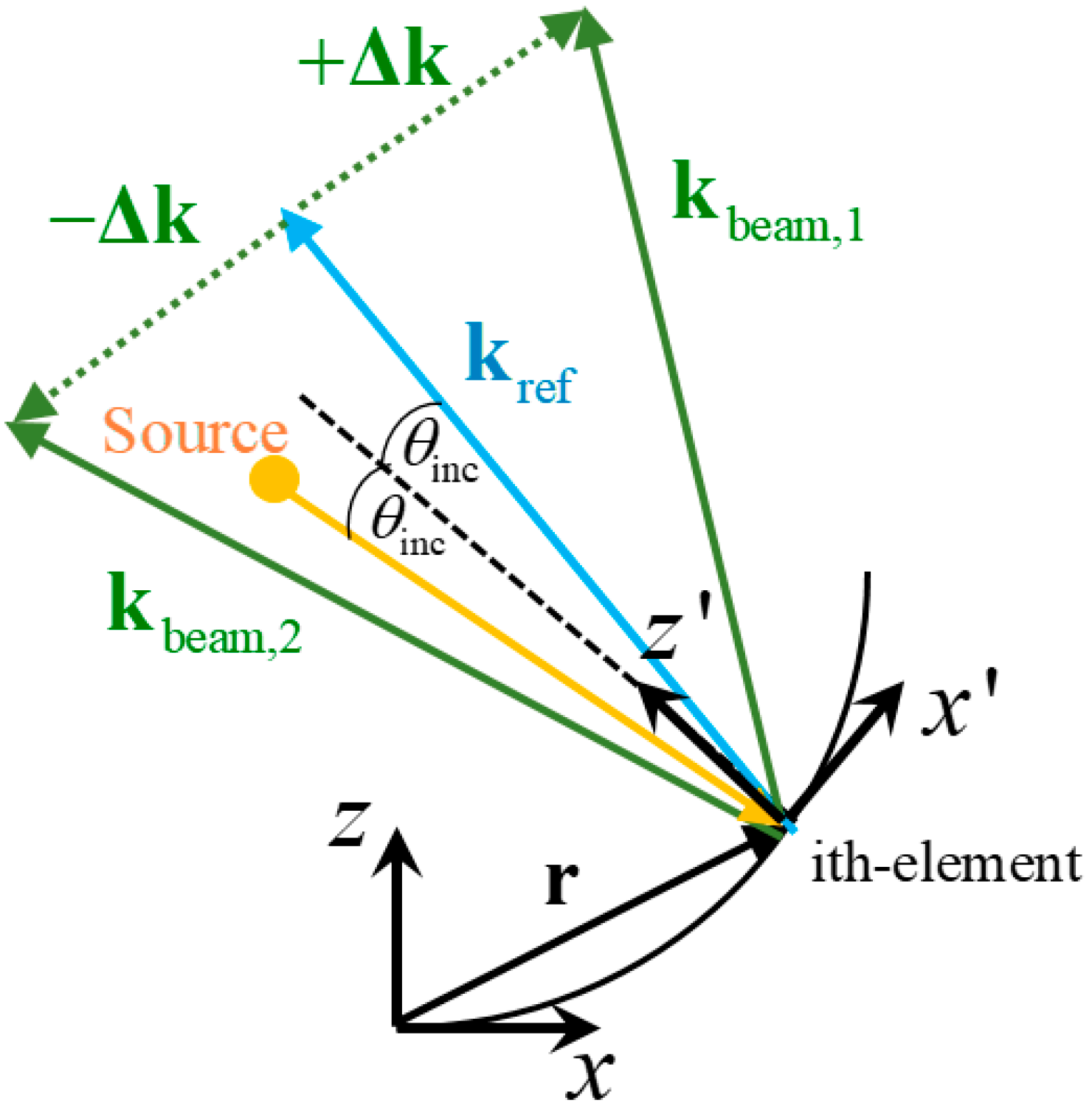
Figure 1 shows the side view of a reflectarray on an arbitrary reflector surface with the phase center of the feed at the source point. In this section, we present an easy technique for computing the required phase distribution to be added in reflected waves by the rotating elements in order to tilt dual CP focused beams in specular directions. Ray optics theory is considered in this formulation.
Let us consider the impinging wave on the
i-th element of the reflectarray with propagation vector given by
where
is the vacuum wavenumber at the working frequency and
,
are the spherical angular coordinates of the impinging wave in the local reference system on the
i-th element (see
x’–
z’ axis in
Figure 1). According to the law of reflection, a reflected wave will be produced with the propagation vector
. In this way, the phase of the reflected wave will be
, where
is the vector position of the
i-th element of the reflectarray with respect to the global reference system shown in
Figure 1 (see the
x–
z axis in
Figure 1). Now, let us consider a desired reflected wave with propagation vector given by
, where
and
are the spherical angular coordinates of the desired beam direction in the local reference system on the
i-th element (see again the
x’-
z’ axis in
Figure 1). In order to obtain the desired reflected wave with the desired beam direction, the
i-th element should introduce to the reflected wave the additional phase given by:
On the other hand, let us consider a reflected wave with propagation vector
(
Figure 1), where
and
are the spherical angular coordinates of the specular beam direction in the local reference system on the
i-th element (see again the
x’–
z’ axis in
Figure 1). According to
Figure 1, this direction of the reflected wave is the specular direction of the direction given by
with respect to the propagation vector
. In order to obtain this reflected wave with this specular beam direction, the
i-th element should introduce to the reflected wave the additional phase given by:
The additional phases given in (1) and (2) are of equal magnitude and opposite sign. These opposite additional phases can be added to the phase of the reflected wave using the same layout by VRT [
15]. Note that the additional phases given in (1) and (2) can be computed by an arbitrary surface (i.e., the vector position
does not suffer any constraint). In fact, the proof of the concept is demonstrated experimentally in [
22] when the arbitrary surface is a flat surface for non-focused beams in CP. In this work, we considered the particular case of a parabolic surface to apply the VRT. The parabolic surface focuses the beams in CP while the VRT is applied to introduce the additional phases given in (1) and (2) to the phase of the reflected waves to produce two focused beams in specular directions.
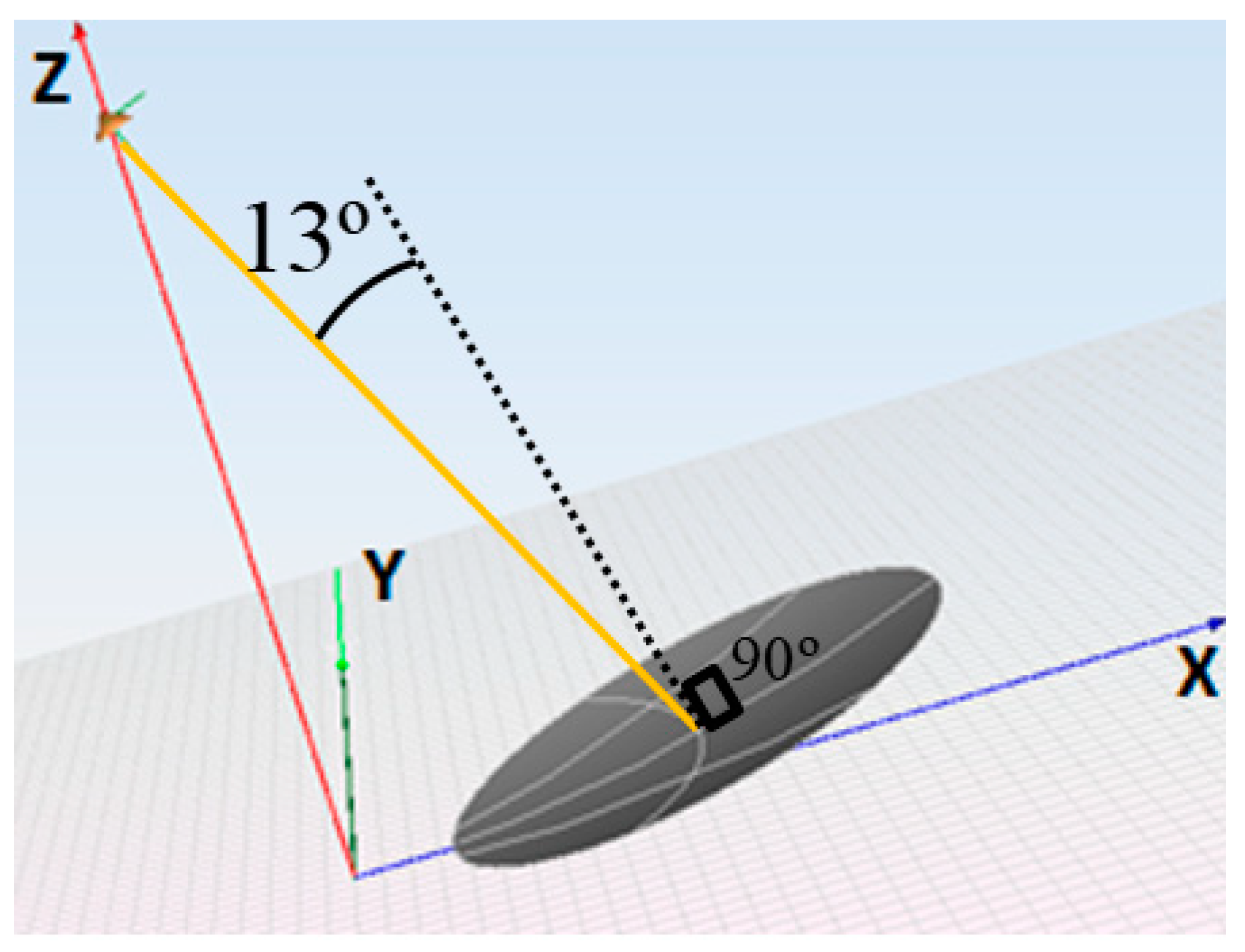
We consider an offset parabolic reflector shown in
Figure 2 with parabola vertex at the coordinate origin. The remaining geometric parameters are the following: focus in the
z-axis at 2.718 m height, symmetry plane of the parabola at
y = 0, diameter of the disk of 1.812 m, clearance of 0.35 m (focal length/diameter ratio is 1.5). The
kref direction of the main beam without introducing the opposite additional phases is the
z-axis. The specular desired directions were
,
deg and
,
of the main beams.
The incident angle θinc which suffers the central element of the parabolic reflectarray is 13.03 deg. Note that for most elements of the parabolic reflectarray, the incident angle θinc can be approximated by its value at the center of the parabolic reflectarray. This will be exploited in the next section in order to optimize the reflectarray element to provide few calls to the full-wave analysis routine in the design process to reduce the consumption of CPU time in the design process.
For this reflector, the maximum and minimum values of the additional phase given by (1) were obtained for the extreme values of
x coordinates, which were 0.35 m and 2.162 m, respectively. The difference of the values that takes in the extreme values for
was 3.66 radians at 19.7 GHz. If we consider the value of the additional phase given by (1) for the center of the disk, we note that the phase change was only 1.83 radians from this center to any extreme point of the disk (i.e., only 105 deg). According to [
15,
19] there is a rule stating that the phase shift added by the rotating element is twice the rotation angle. This rule is quite accurate when the elements are much smaller than the operation wavelength. In that case, the coupling between elements should not change much with rotation. However, as shown in the next section, the proposed reflectarray element has a period size roughly half of the operation wavelength and the variation of the coupling with rotation is not negligible. So, using the rule that the phase shift added by the rotating element is twice the rotation angle, we can state that regarding the angular rotation value at the center of the disk, the unit element rotation angle is always in the range from −52.5 to +52.5 degrees.
3. Design and Optimization of The Rotating Element of the Reflectarray
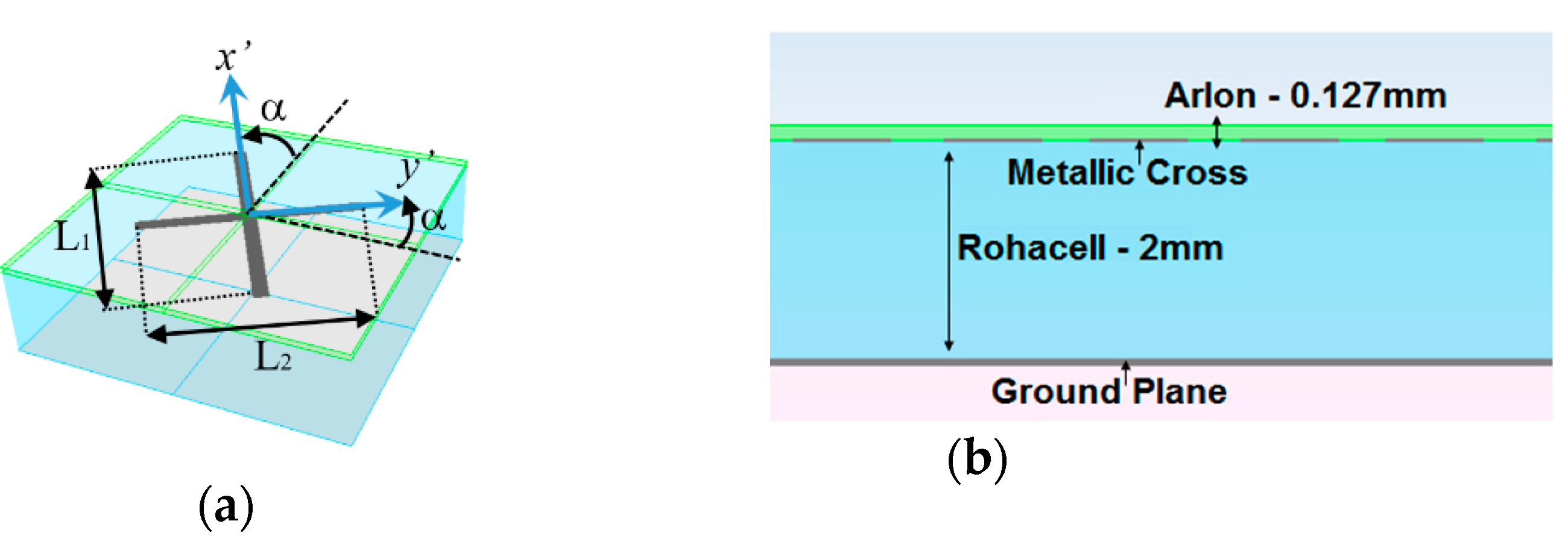
We consider a left-handed circular polarized (LHCP) impinging plane wave on a multilayer periodic structure with the unit cell shown in
Figure 3. This unit cell is made of two dielectric layers. The bottom 2 mm dielectric layer comprised of Rohacell material is used as separator with the ground plane. The upper 0.127 mm dielectric layer comprised of Arlon material is used to host a conductive cross printed on its lower limit as shown in
Figure 3b. The reflectarray cells have a quasi-periodicity, with a period in mm of 7.6 × 7.6 (0.499 × 0.499 in wavelengths). This reflectarray element was used in [
22] in order to demonstrate experimentally the proof of the concept of generating two beams in specular directions for CP, and satisfactory results were obtained.
The direction of the impinging plane wave is the
direction and its electric field is expressed as:
where
and
are the unitary vector parallel to the
x’ and
y’ axes as shown in
Figure 3a. These unitary vectors are parallel to the larger and shorter cross arms of
Figure 3a. According to [
19] and [
23], when the LHCP wave is incident on the periodic structure, the electric field of the reflected wave has two contributions of circularly polarized waves: a co-polar contribution given by an LHCP wave and a cross-polarization contribution given by a right-handed circularly polarized (RHCP) wave. Both circularly polarized waves propagate in the positive direction +
,
where
Rx’x’ and
Ry’y’ are the reflection coefficients for the co-polar components in directions of the
x’ and
y’ axes, respectively, as shown in
Figure 3a (i.e., in the directions of the crossed arms) and α is the angle of rotation of the crosses shown in
Figure 3a. In (4) it is assumed that cross-polarization reflection coefficients
Rx’y’ and
Ry’x’ are negligible. This assumption is based on the symmetry of the reflectarray element. For example, let us consider an impinging plane wave with its electric field linearly polarized in
x’. In the cross arm oriented in the
x’ direction, due to the symmetry of the arm regarding the
x´ axis, there is no reason to expect a contribution to the reflected electric field with
y´ polarization. The same rationale can be applied for the cross arm oriented in the
y´ direction. As will be shown later, this assumption leads to an equation which predicts the level of the cross-polarization contribution of a circularly polarized wave with enough accuracy for practical purposes. Note that the first contribution in (4) is the co-polar reflected electric field of an LHCP wave, since the impinging waves propagate in the -
direction and the reflected wave propagates in +
direction. The second contribution in (4) is the cross-polarization reflected electric field of an RHCP wave. According to (4), when
, a pure reflected LHCP wave is obtained (there is no cross-polarization contribution). Moreover, the added phase shift by the rotating element to the reflected electric field of this pure LHCP wave is −2α. Indeed, when
Rx’x’ = −
Ry’y’, the reflected field is:
Note that when there is no rotation, the phase shift of the reflected electric field of the pure LHCP wave is equal to the phase of the Rx’x’ reflection coefficient. The phase of Rx’x’ offers an additional degree of freedom to modify the phase of the reflected wave in (5). This additional degree of freedom can be exploited by means of the use of conductive cross. In the case of conductive cross, roughly independent phase control of reflection coefficients Rx’x’ and Ry’y’ is possible from independent variations of the lengths L1 and L2. This independent phase control provides more flexibility in the design process since the condition can be satisfied for several values of the phase of Rx’x’. These several values of the phase of Rx’x’ can be used in order to correct phase errors. For example, a small phase correction can be added on both polarizations to improve the beam shaping.
In a similar way, when the impinging wave is RHCP, and
Rx’x’ = −
Ry’y’, the reflected electric field of the contribution of the RHCP wave will suffer a phase shift with opposite sign, +2α, as stated in [
15]. When the condition
is not exactly fulfilled, else
, where an
is an error in the phase, then the cross-polarization contribution in (4) will be given by:
Note that this cross-polarization contribution does not depend on the rotation angle, and only depends of the error in the phase . So, the amplitude of the cross-polarization contribution increases as this phase error increases. Recall that (6) was obtained under the assumption that cross-polarization reflection coefficients Rx’y’ and Ry’x’ are negligible. This equation predicts the cross-polarization level in the circularly polarized reflected wave.
A parametric study of the rotating element of the unit cell shown in
Figure 3 was carried out in order to check the performances of the previously shown co-polar and cross-polarization contributions. This parametric study was carried out with the periodic structure module of the newFASANT suite [
21]. In this parametric study, the working frequency was 19.7 GHz. Since the incident angle
in most elements of the parabolic reflectarray can be approximated by the incident angle at the center of the parabolic reflectarray, the incident angles
and
were considered in the parametric study. Since variations of the lengths L
1 and L
2 produce roughly independent variations on the phase of
Rx’x’ and
Ry’y’, these lengths can be adjusted to comply with the condition
. There are many pairs of lengths (L
1, L
2) which provide 180° phase difference. The selected lengths were L
2 = 4.9 mm and L
1 = 6.025 mm. A parametric study of rotating of the cross was performed considering the arms’ lengths obtained in the previous adjustment.
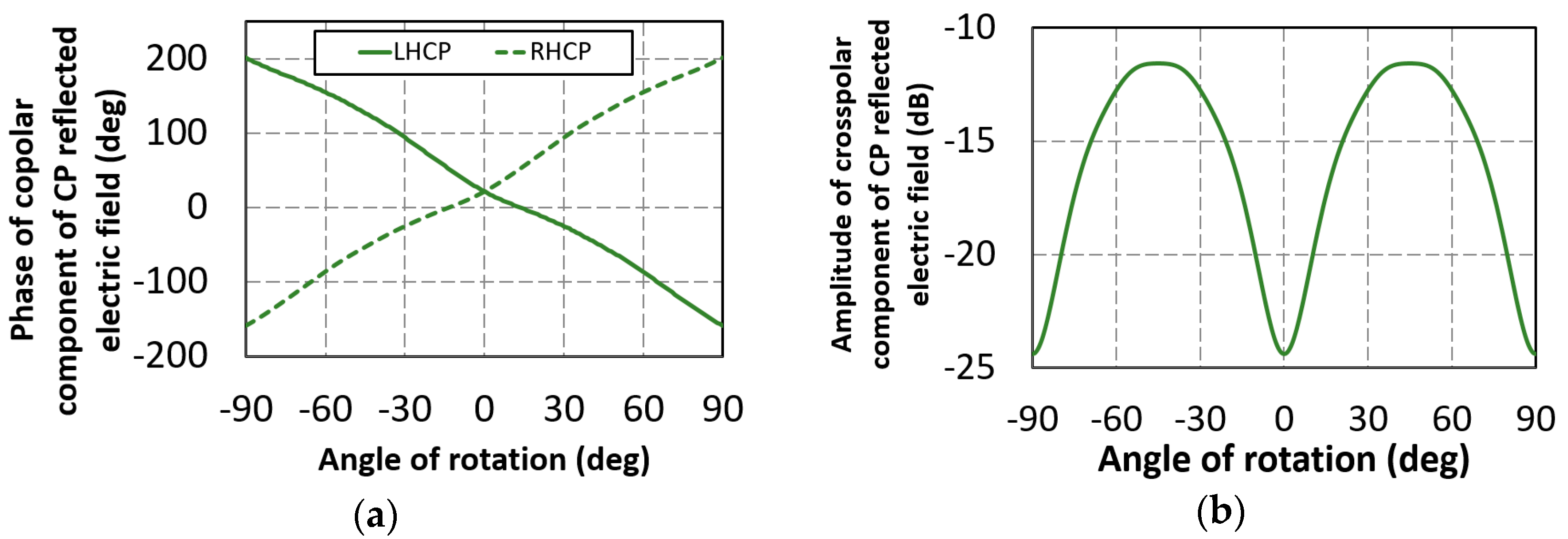
Figure 4a shows the phases of the reflected electric fields of the co-polar circularly polarized waves with respect to the rotation angle. The phase for RHCP increased with the rotation angle with an opposite sense to the phase for LHCP, as predicted in (5). The amplitude of the reflected electric field of the cross-polar circularly polarized wave for the RHCP incident wave is shown in
Figure 4b. Similar results were obtained for the LHCP incident wave. In this figure we notice that the amplitude of the reflected electric field of the cross-polar circular polarized wave was only negligible when the rotating angle was about 0, 90, or −90 degrees (i.e., a pure RHCP reflected wave is produced). However, for 45 or −45 degrees it was far from being negligible.
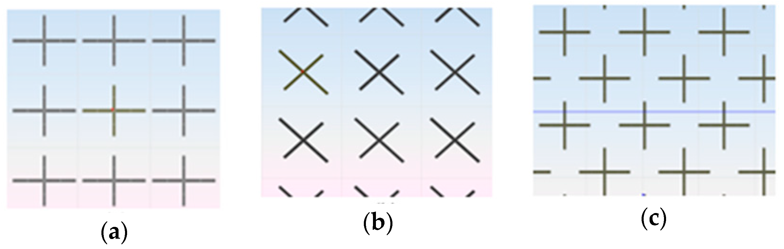
This behavior can be explained considering the views of the periodic lattice for two values of the rotational angle: 0 and 45 degrees. We can compare the reflected waves of a linearly polarized incident wave whose components were parallel to the cross arms for rotating angle values of 0 and 45 degrees. If for this case we compare the geometry visualized in
Figure 5a,b it is obvious that we had two different periodic structures and therefore it could happen that the geometry of
Figure 5c would not give a 180 deg phase shift between the linear co-polar reflection components (i.e., the condition
is not satisfied), although the geometry was adjusted to give that shift when the rotating angle was 0° (i.e., the cross was optimized for a 0° rotation angle but not for 45 deg rotation).
To avoid the issues found in the previous parametric study, a few pairs of lengths (L
1, L
2) were optimized in order to fulfill the condition
. The first pair of lengths was optimized when there was no rotation. The obtained values were L
1 = 6.0 and L
2 = 4.9 mm. According to previous discussion and
Figure 5, the geometry lattice at the rotation angle of 22.5 and 45 degrees differed significantly from the geometry lattice for the non-rotated cross. So, the values of L
1 = 6.0 and L
2 = 4.9 mm would provide significant phase error values
and similar high cross-polarization level to those shown in
Figure 4b. So, length optimization was imposed at the rotation angles of 22.5 and 45 degrees to avoid the high values of cross-polarization level. In this way, the second and third pairs of lengths were optimized to fulfill the condition
for rotation angles 22.5 and 45.0 degrees. The obtained values were L
1 = 6.14, L
2 = 4.91 mm for the rotation angle of 22.5 deg and L
1 = 6.24, L
2 = 4.92 mm for the rotation angle of 45.0 deg. We checked that the optimized values of the pair (L
1, L
2) for rotation angles of 22.5 and 45.0 degrees also roughly fulfilled the condition
for rotation angles of −22.5 and −45.0 degrees. Note that two pairs of them provided a 180deg difference of phase for a rotation angle of 45deg (i.e., for significant change of the periodic lattice). Therefore, we have for the (−52.5, 52.5) deg range of the rotation angle samples each 22.5deg for the lengths of the cross arms that were optimized for the VRT. These samples defined six angular intervals in the (−52.5, 52.5) deg rotation range. So, the pairs of lengths were obtained for any rotation angle by linear interpolation in the corresponding angular interval. The interpolation in these six angular intervals would provide few calls to a full-wave analysis routine in the design process of the parabolic reflectarray and the CPU time of the design process would be reduced.
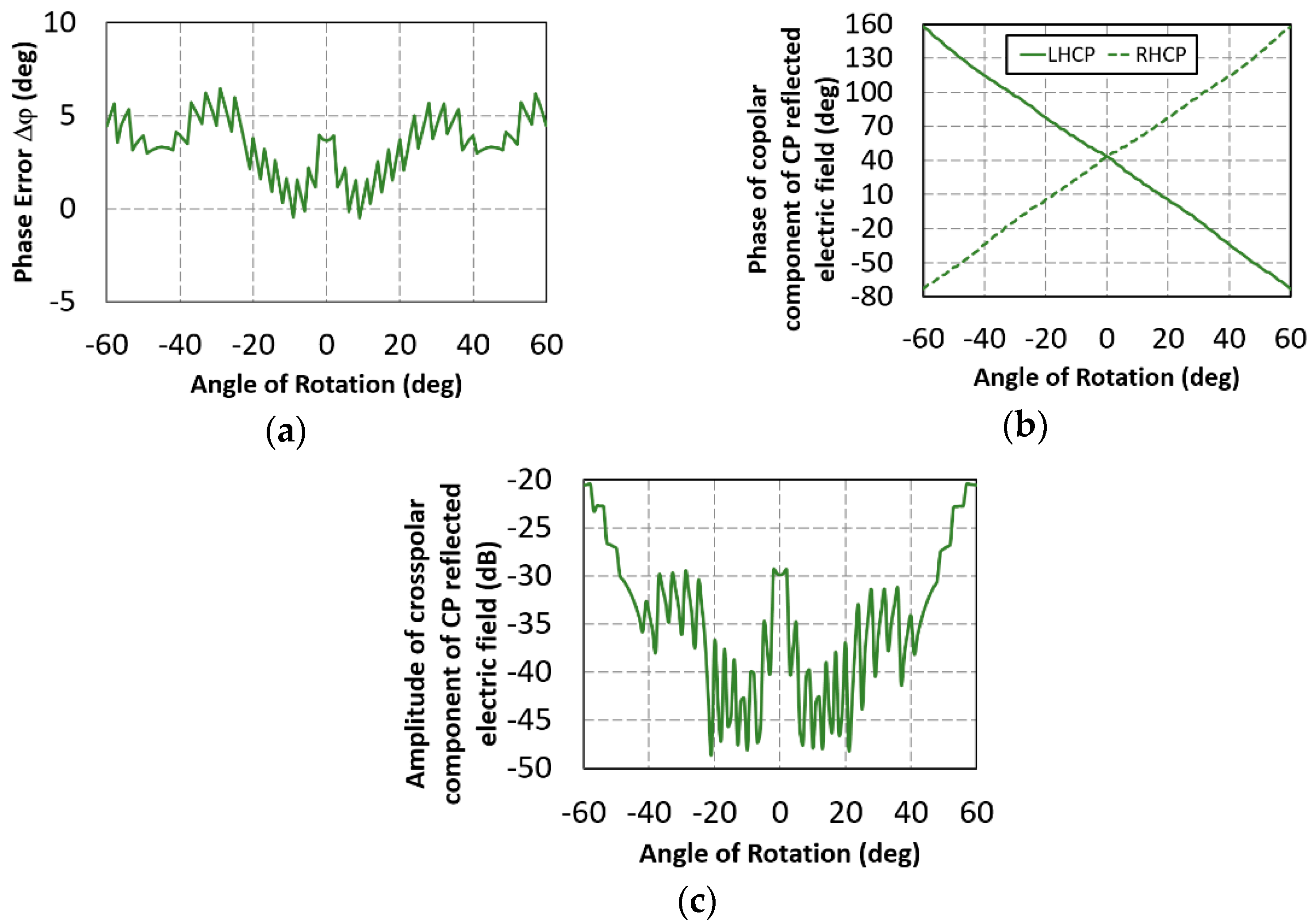
Figure 6a shows the value of the phase error Δ
φ produced in the 180° of difference of phase between the reflection coefficients
Rx’x’ and
Ry’y’ at 19.7 GHz. These values of phase error are shown as a function of the rotation angle. A maximum phase error of 7° was obtained. This phase error predicts −24 dB of amplitude of the reflected electric field of the cross-polar circularly polarized wave (see (6) with E
0 = 1).
Figure 6b shows the phase of the reflected electric field of the co-polar circular polarized wave as a function of the rotation angle. Very linear dependence with respect of rotation angle was obtained. These dependences were roughly +2α for RHCP and -2α for LHCP reflected waves, as expected from (5). The amplitude of the reflected electric field of the cross-polar circularly polarized wave for RHCP incident wave is shown in
Figure 6c. Similar cross-polarization results were obtained for an LHCP incident wave. We see that the cross-polarization level was between −30 and −20 dB, as predicted from (6).


