Experimental Study on the Reinforcement of Prestressed Concrete Cylinder Pipes with External Prestressed Steel Strands


Abstract
:1. Introduction
2. Test Scheme
2.1. Test Materials
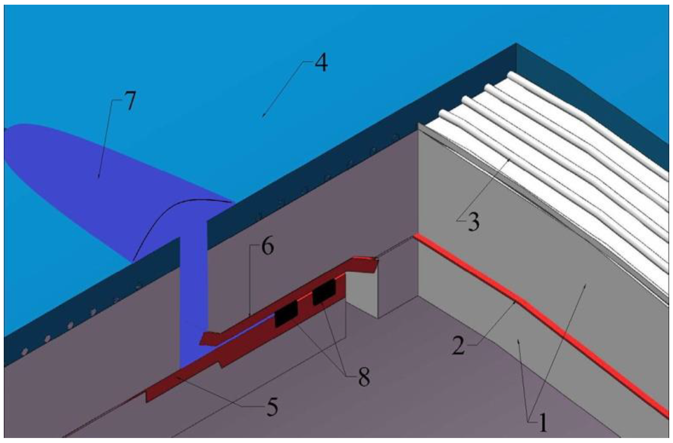
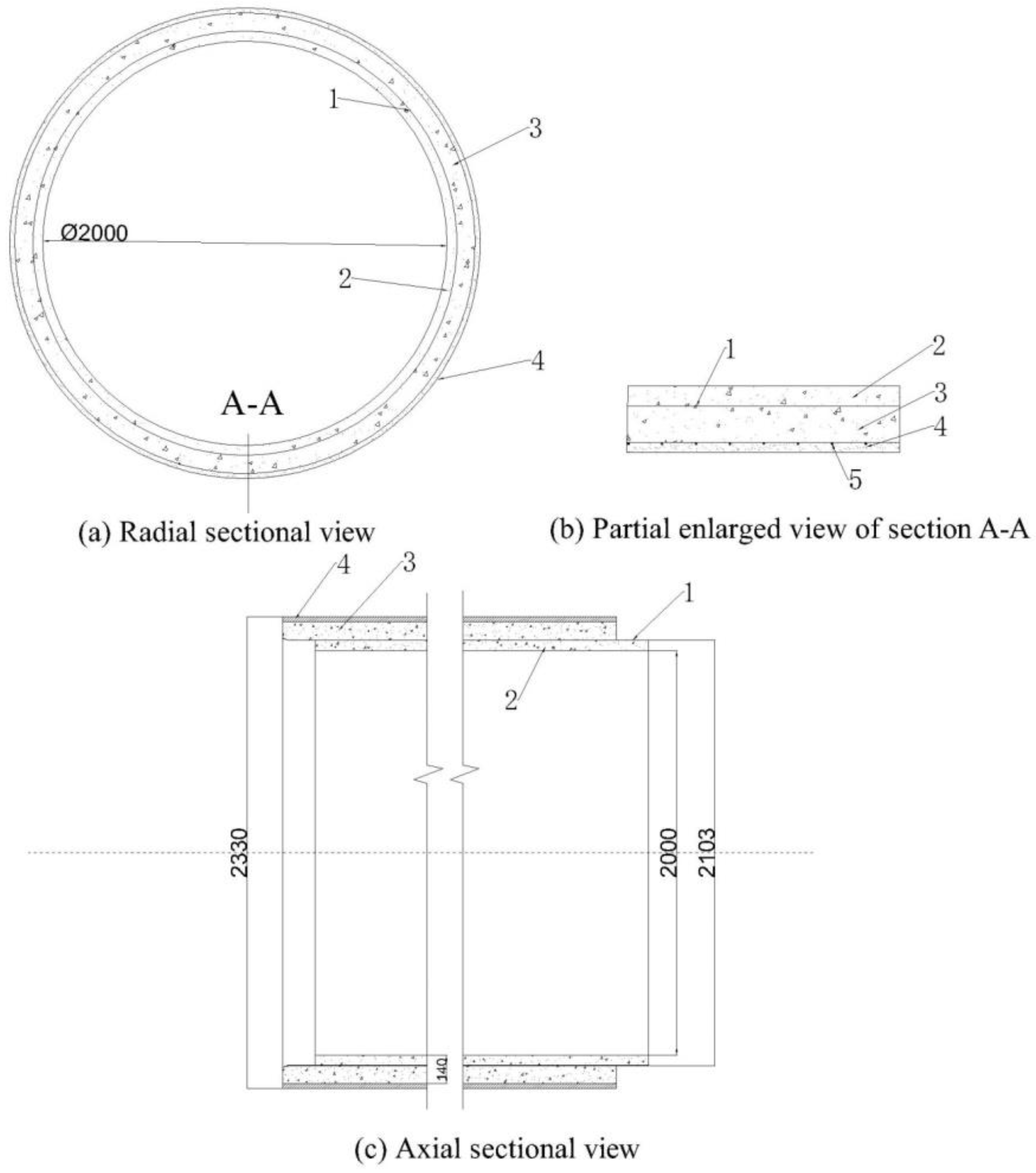
2.1.1. Prestressed Concrete Cylinder Pipe (PCCP)
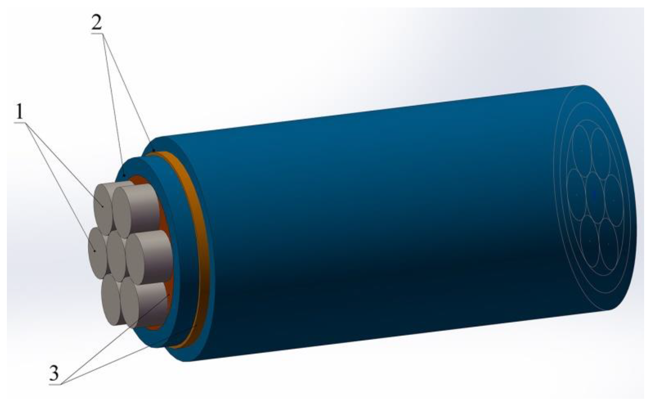
2.1.2. Steel Strand
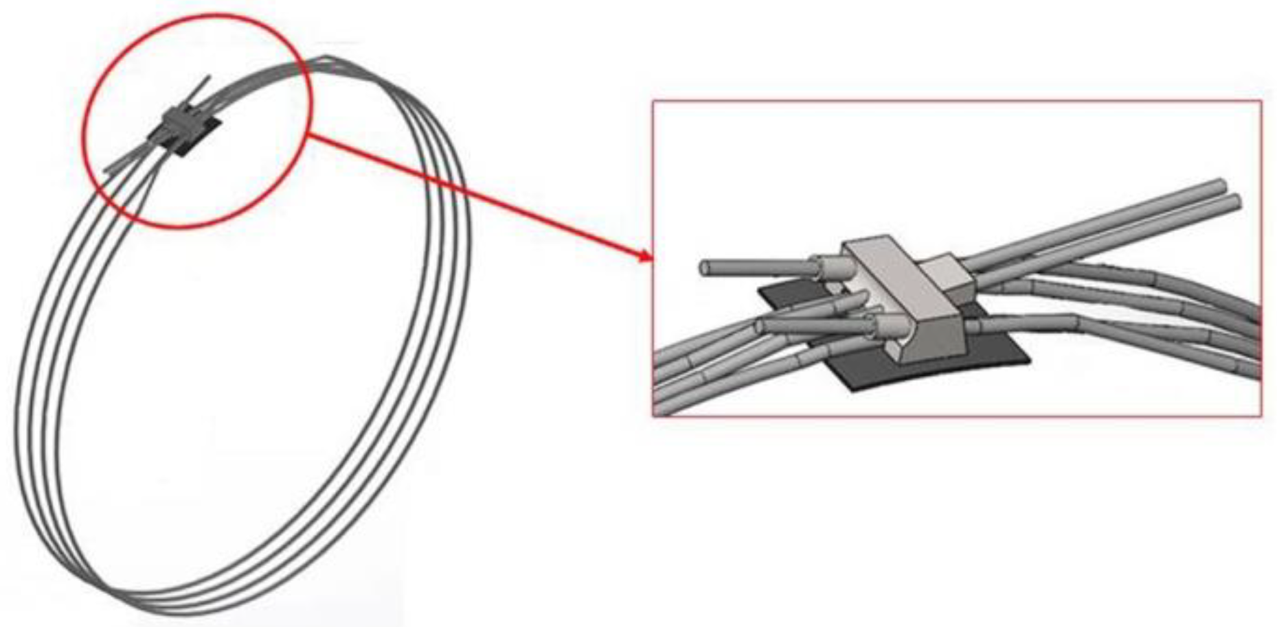
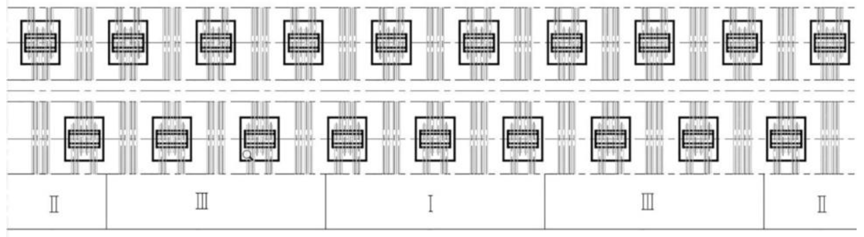
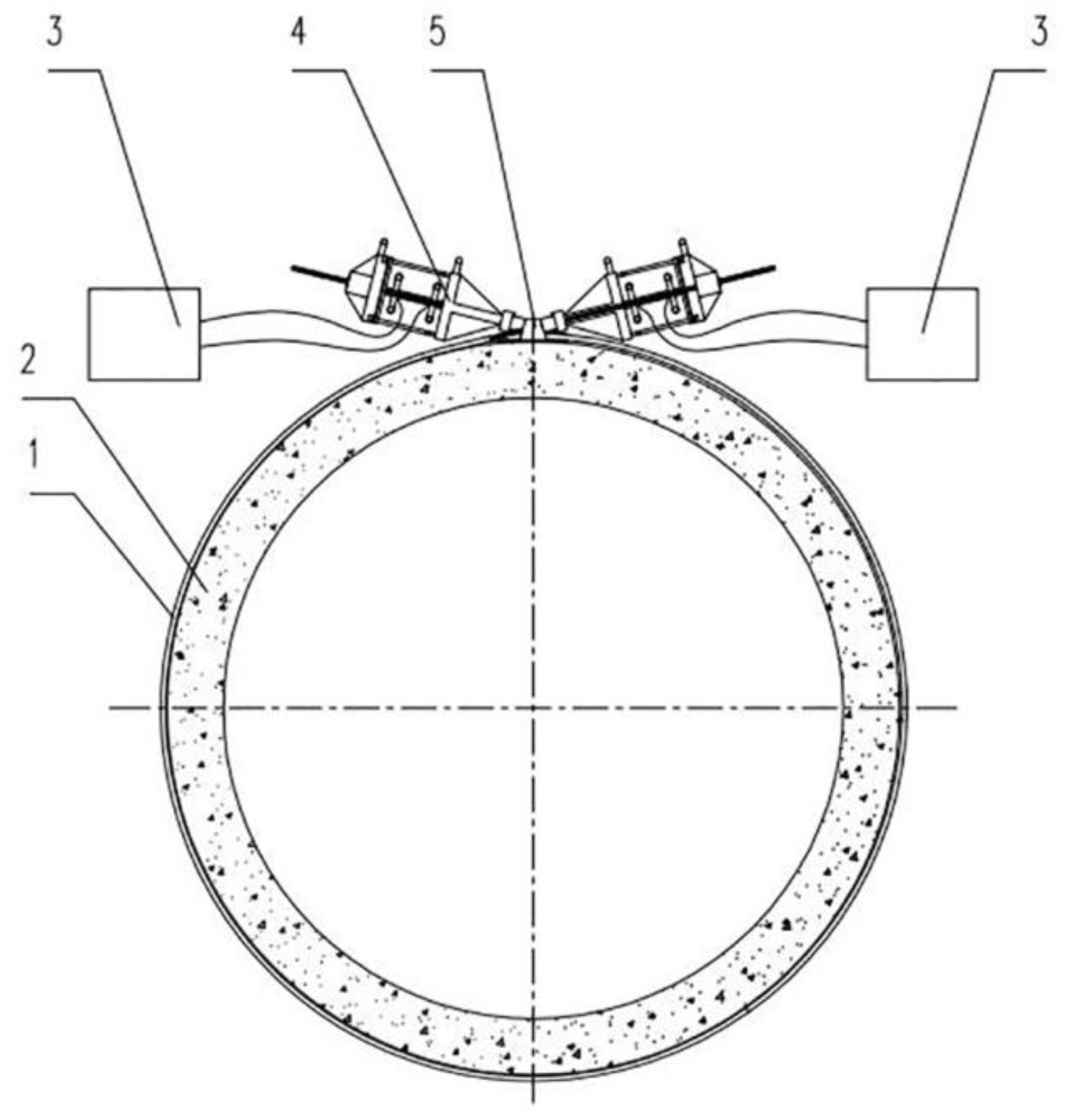
2.2. Test Apparatus
2.3. Test Procedures
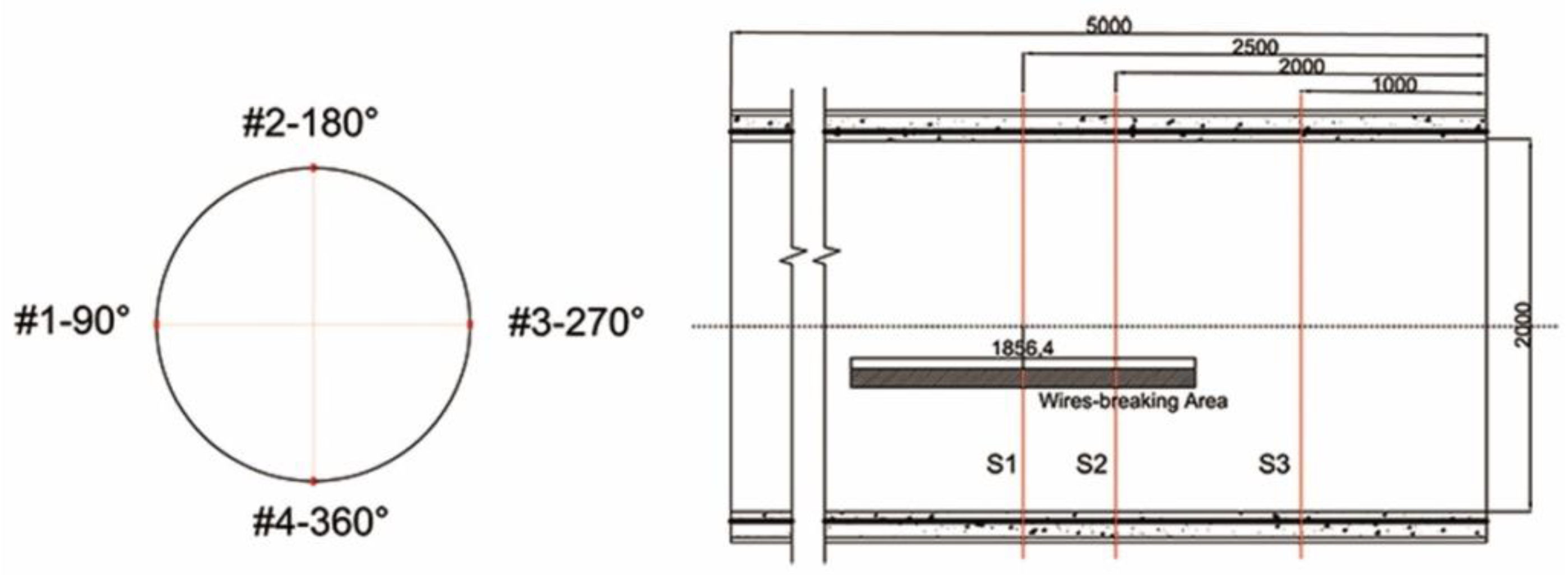
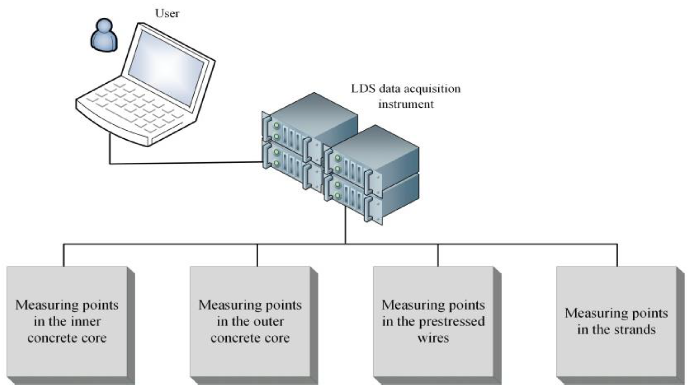
2.4. Monitoring Content
3. Test Results and Discussion
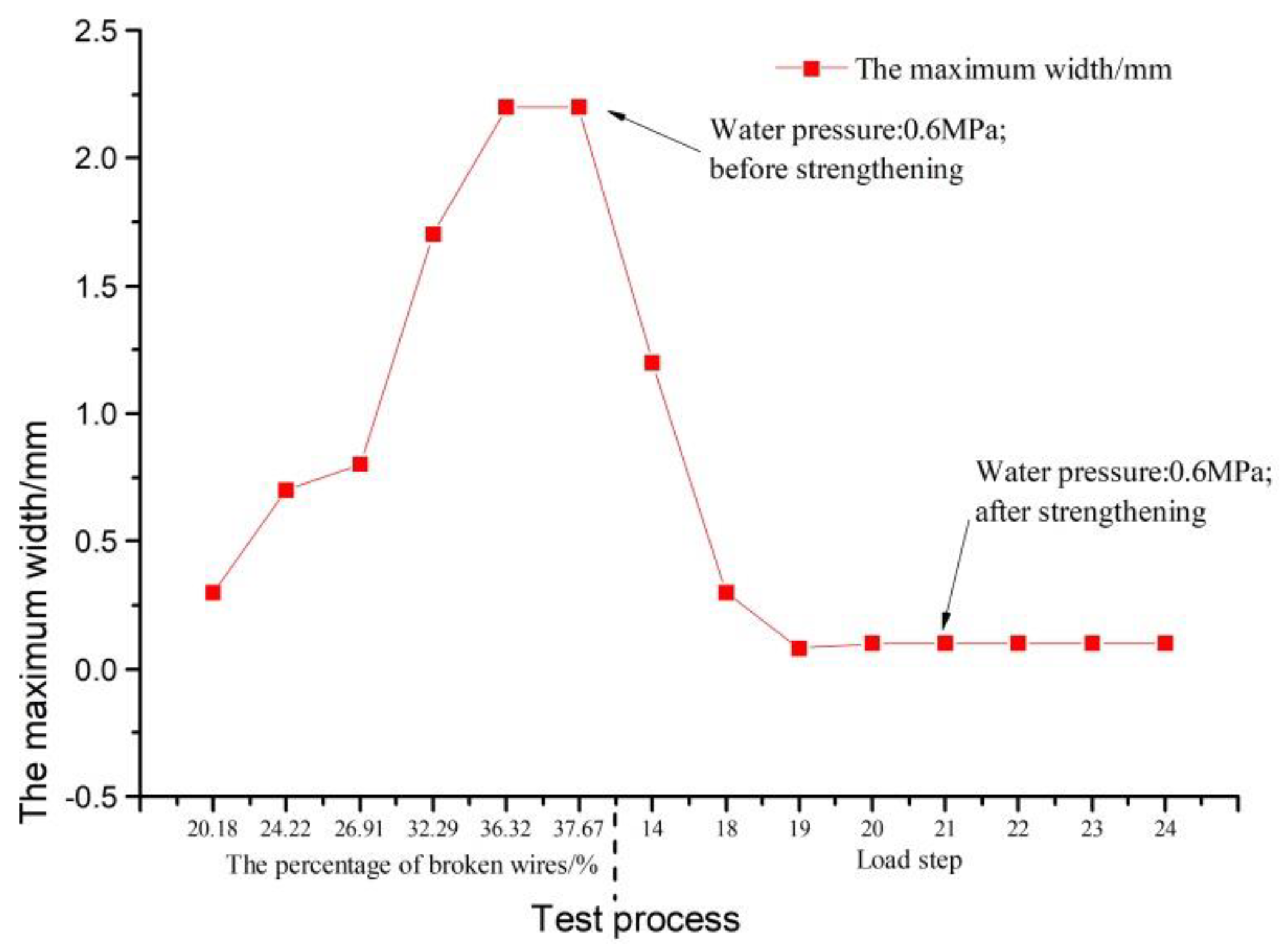
3.1. Results Revised
- —total area of prestressing wire (mm2/m),
- —core concrete area (including steel-cylinder area, mm2/m),
- —steel cylinder area (mm2/m),
- —gross wrapping stress in prestressing wire (MPa),
- , —modular ratio of prestressing wire to core concrete at wrapping and at maturity,
- , —modular ratio of steel cylinder to core concrete at wrapping and at maturity,
- , , —design modulus of elasticity of core concrete, prestressing wires and steel cylinder,
- —design shrinkage strain for a buried pipe,
- —design creep factor for a buried pipe,
- —wire-relaxation factor for a single layer of prestressing.
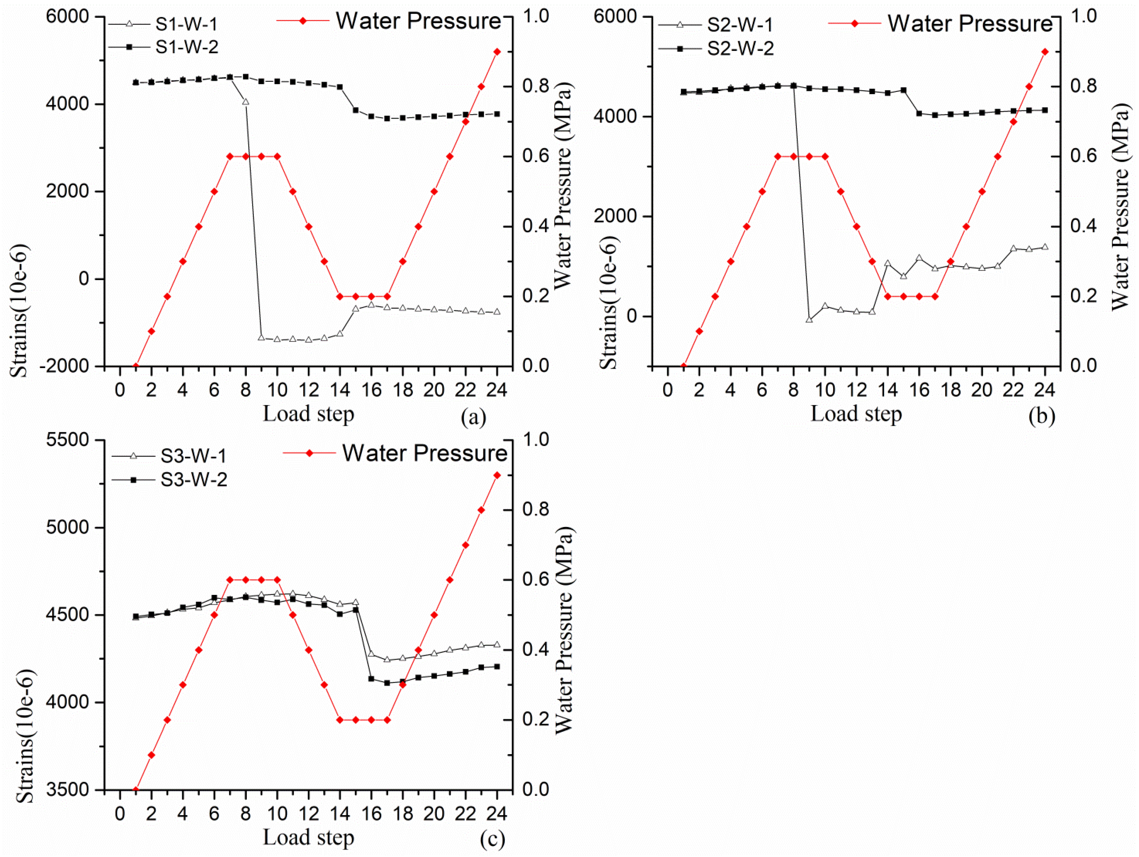
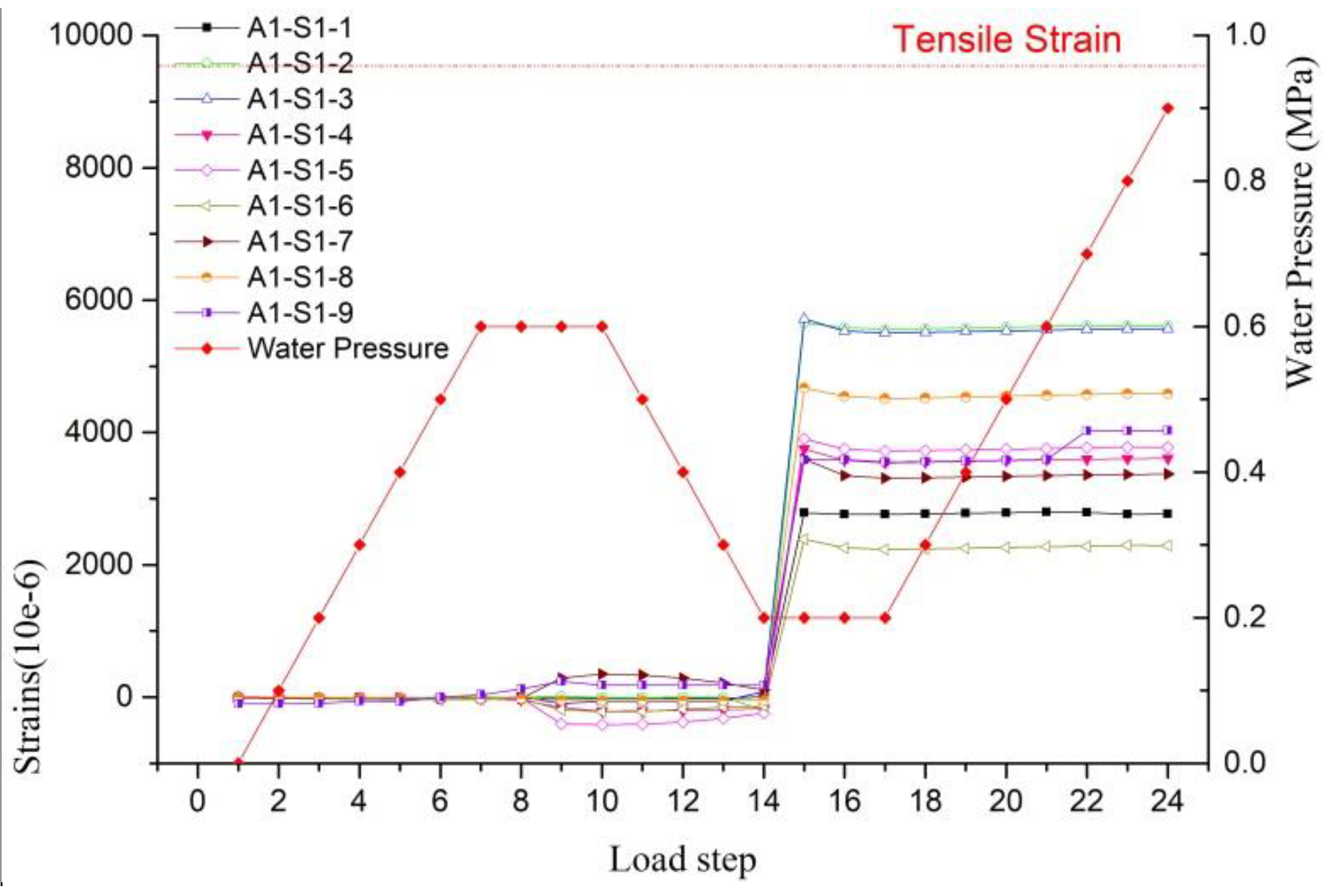
3.2. Prestressing Wires
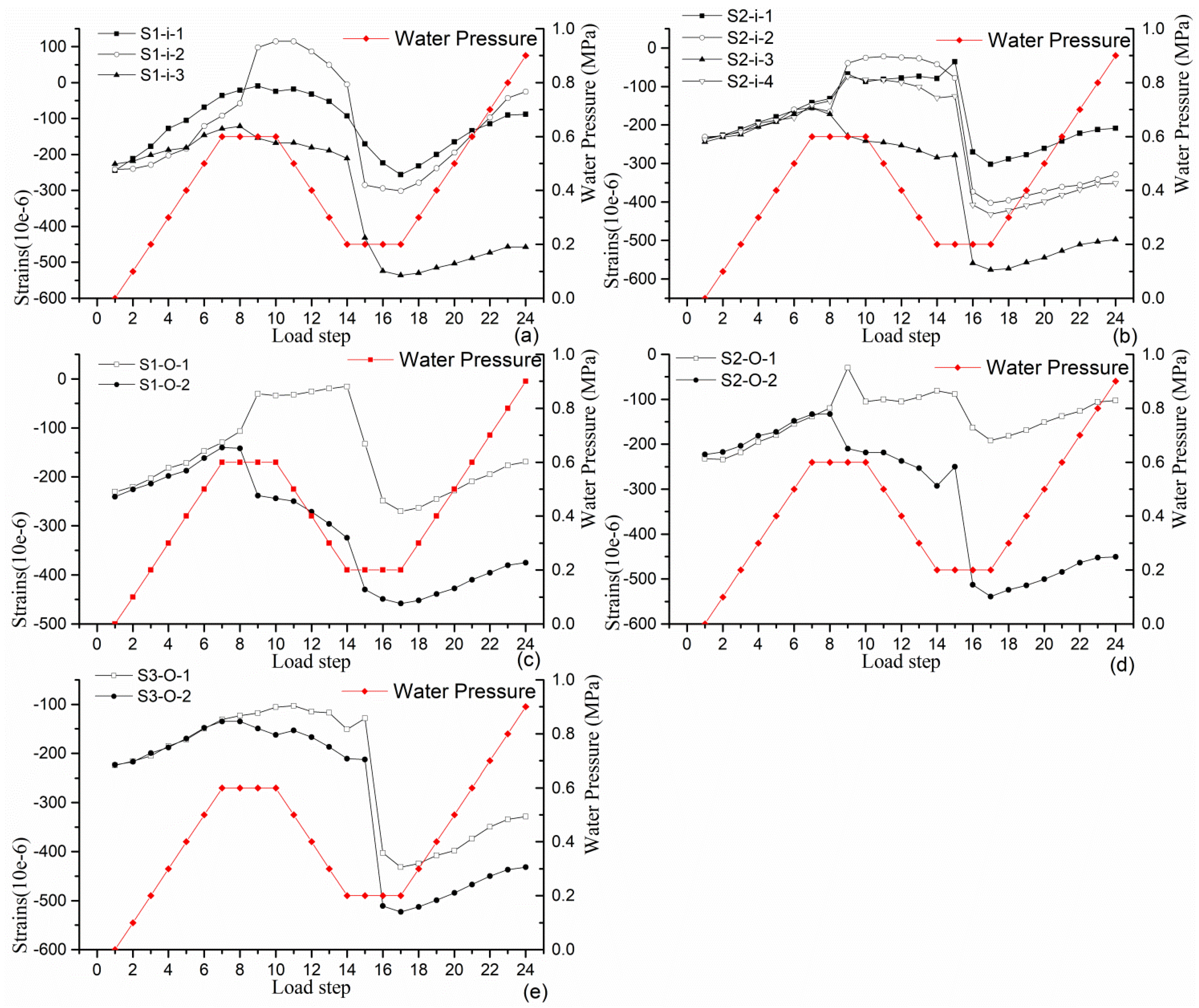
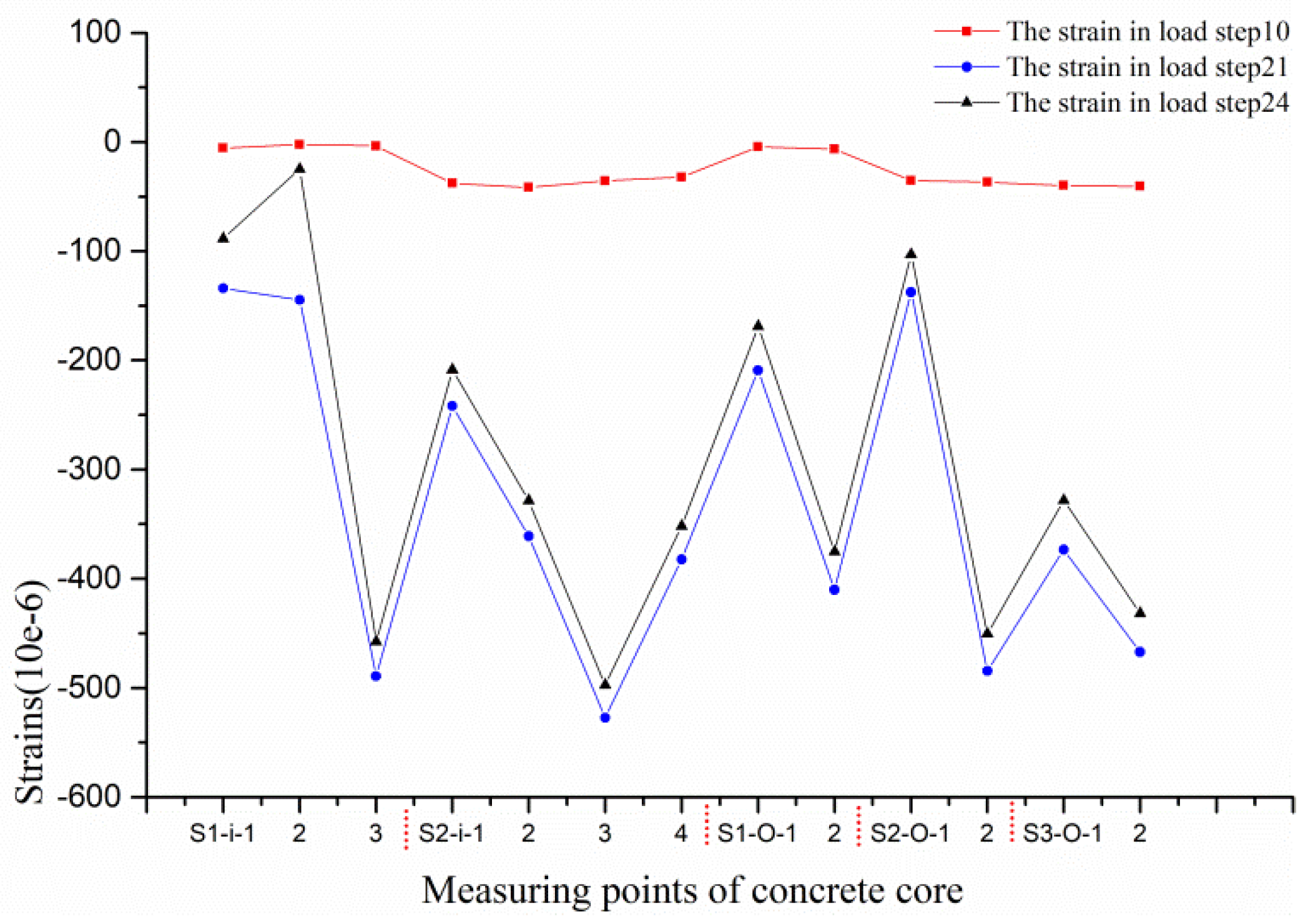
3.3. Concrete Core
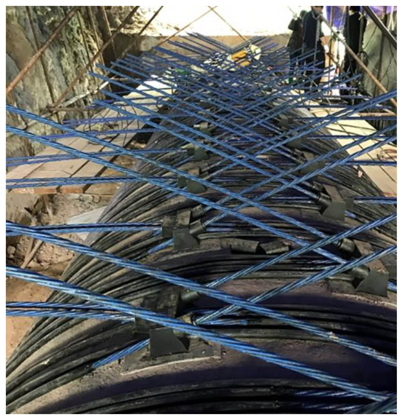
3.4. Prestressed Strands
4. Conclusions
Author Contributions
Funding
Acknowledgments
Conflicts of Interest
References
- Ge, S.Q.; Sinha, S. Failure Analysis, Condition Assessment Technologies, and Performance Prediction of Prestressed-Concrete Cylinder Pipe: State-of-the-Art Literature Review. J. Perform. Constr. Facil. 2014, 28, 618–628. [Google Scholar] [CrossRef]
- Roller, J.J. PCCP Risk Management-State of the Art and Strategy; American Water Works Association: Denver, CO, USA, 2013. [Google Scholar]
- Du, X.Y. Study on key techniques for design of PCCP for long-distance diversion project. Water Resour. Hydropower Eng. 2015, 46, 37–49. [Google Scholar]
- Zhang, C. Analysis on the Stress of Prestressed Concrete Cylinder Pipe during Wire Winded; Institute of Water Conservancy & Environment Zhengzhou University: Zhengzhou, China, 2015. [Google Scholar]
- Ge, S.Q.; Sunil, S. Effect of Mortar Coating’s Bond Quality on the Structural Integrity of Prestressed Concrete Cylinder Pipe with Broken Wires. J. Mater. Sci. Res. 2015, 4, 59–75. [Google Scholar] [CrossRef]
- Ball, R.T.; Moore, W.G.; Smith, D.L.; Stubblefield, N.D.; Wahlquist, R.W. Prestressed Concrete Cylinder Pipe Rehabilitation Repair and Replacement: Large Diameter Success Stories. Fla. Water Resour. J. 2012, 4–10. [Google Scholar]
- Rahman, S.; Smith, G.; Mielke, R.; Keil, B. Rehabilitation of Large Diameter PCCP: Relining and Sliplining with Steel Pipe. In Proceedings of the Pipelines 2012: Innovations in Design, Construction, Operations, and Maintenance -Doing More with Less, Miami Beach, FL, USA, 19–22 August 2012; pp. 494–504. [Google Scholar]
- Kenny, M.K.; Rahman, S. San Diego County Water Authority Aqueduct Protection Program since 1992: Evolution in Design and Construction of Steel Cylinder Relining of PCCP. In Proceedings of the Pipelines 2014: From Underground to the Forefront of Innovation and Sustainability, Portland, OR, USA, 3–6 August 2014. [Google Scholar]
- Ambroziak, M.; Kelso, P.E.B.; Sinclair, J. Development and Construction of the Nations Largest Water Main Rehab Project. In Proceedings of the Pipelines 2010: Climbing New Peaks to Infrastructure Reliability: Renew, Rehab, and Reinvest, Keystone, CO, USA, 28 August–1 September 2010; pp. 51–60. [Google Scholar]
- Zarghamee, M.S.; McReynolds, M. Retrofit of CFRP Installation to Meet Current Design Standard. In Proceedings of the Pipelines 2013: Pipelines and Trenchless Construction and Renewals—A Global Perspective, Forth Worth, TX, USA, 23–26 June 2013; pp. 1258–1267. [Google Scholar]
- Zarghamee, M.S. MuratEngindeniz, CFRP Renewal of PCCP—An Overview. In Proceedings of the Pipelines 2014: From Underground to the Forefront of Innovation and Sustainability, Portland, OR, USA, 3–6 August 2014; pp. 932–941. [Google Scholar]
- Dou, T.S.; Cheng, B.Q.; Hu, H.; Xia, S.F.; Zhao, L.J. The experimental study on CFRP renewal of PCCP with broken wires. China Concr. Cem. Prod. 2017, 12, 35–40. [Google Scholar]
- L-Hacha, R.E.; Elbadry, M. Strengthening Concrete Beams with Externally Prestressed Carbon Fiber Composite Cables: Experimental Investigation. PTI J. 2006.
- Elnakhat, H.; Raymond, R. Repair of PCCP by Post Tensioning. In Proceedings of the Pipelines 2006, Chicago, IL, USA, 30 July–2 August 2006; pp. 1–5. [Google Scholar]
- AWWA C304 Standard for Design of Prestressed Concrete Cylinder Pipe; American Water Works Association: Denver, CO, USA, 2015.
- Ojdrovic, R.; la Bonte, G. Inspection, Failure Risk Analysis, and Repair of Cooling-Water Lines in One Outage. In Proceedings of the Pipelines 2008: Pipeline Asset Management: Maximizing Performance of our Pipeline Infrastructure, Atlanta, GA, USA, 22–27 July 2008; pp. 1–10. [Google Scholar]
- Ye, Z. The External Prestressing and Carbon Fiber Reinforced Joint Concrete Continuous Beam Research; Jilin Architecture and Civil Engineering Institute: Changchun, China, 2012. [Google Scholar]
- Ma, Z. Study on the application of CFRP prestressed tendons in precast segmental bridge. J. Transp. Sci. Eng. 2017, 33, 50–55. [Google Scholar]
- Feng, X.Z. Comparison of ASTM Concrete Compressive Strength and China’s Concrete Strength Grade. Northwest Hydropower 2008, 3, 65–67. [Google Scholar]


| Key Parameters | Values | Key Parameters | Values |
|---|---|---|---|
| Inner diameter of PCCP/mm | 2000 | Standard compressive strength of concrete/(N/mm2) | 55 |
| Thickness of core concrete/mm | 140 | Modulus of concrete/(N/mm2) | 2.786 × 10⁴ |
| Inner diameter of cylinder/mm | 2100 | Standard compressive strength of mortar/(N/mm2) | 45 |
| Thickness of cylinder/mm | 1.5 | Modulus of mortar/(N/mm2) | 2.535 × 10⁴ |
| Diameter of wires/mm | 6 | Modulus of cylinder/(N/mm2) | 2.069 × 10⁵ |
| Spacing between each wire/mm | 22.1 | Modulus of wire/(N/mm2) | 1.93 × 10⁵ |
| Key Parameters | Values |
|---|---|
| Nominal diameter without PE/mm | 15.2 |
| Nominal section area without PE/mm2 | 140 |
| Nominal tensile strength/(N/mm2) | 1860 |
| Modulus/(N/mm2) | 1.95 × 10⁵ |
| Coefficient of linear expansion/(1/℃) | 1.2 × 10⁻⁵ |
| Outer diameter with PE/mm | 22 |
| Load Stage | Load Step | Details | Internal Water Pressure/MPa |
|---|---|---|---|
| Ⅰ | 1 | Preparation | 0 |
| 2 | Increase internal water pressre, hold for 5 min | 0.1 | |
| 3 | 0.2 | ||
| 4 | 0.3 | ||
| 5 | 0.4 | ||
| 6 | 0.5 | ||
| 7 | 0.6 | ||
| Ⅱ | 8 | Break prestressing wires manually until visible cracks propagate. | 0.6 |
| 9 | 0.6 | ||
| 10 | 0.6 | ||
| Ⅲ | 11 | Decrease internal water pressre, hold for 5 min | 0.5 |
| 12 | 0.4 | ||
| 13 | 0.3 | ||
| 14 | 0.2 | ||
| Ⅳ | 15 | Tensioning operation of steel strands | 0.2 |
| 16 | 0.2 | ||
| 17 | 0.2 | ||
| Ⅴ | 18 | Increase internal water pressre after tensioning, hold for 5 minute | 0.3 |
| 19 | 0.4 | ||
| 20 | 0.5 | ||
| 21 | 0.6 | ||
| 22 | 0.7 | ||
| 23 | 0.8 | ||
| 24 | 0.9 |
© 2019 by the authors. Licensee MDPI, Basel, Switzerland. This article is an open access article distributed under the terms and conditions of the Creative Commons Attribution (CC BY) license (http://creativecommons.org/licenses/by/4.0/).
Share and Cite
Zhao, L.; Dou, T.; Cheng, B.; Xia, S.; Yang, J.; Zhang, Q.; Li, M.; Li, X. Experimental Study on the Reinforcement of Prestressed Concrete Cylinder Pipes with External Prestressed Steel Strands. Appl. Sci. 2019, 9, 149. https://doi.org/10.3390/app9010149
Zhao L, Dou T, Cheng B, Xia S, Yang J, Zhang Q, Li M, Li X. Experimental Study on the Reinforcement of Prestressed Concrete Cylinder Pipes with External Prestressed Steel Strands. Applied Sciences. 2019; 9(1):149. https://doi.org/10.3390/app9010149
Chicago/Turabian StyleZhao, Lijun, Tiesheng Dou, Bingqing Cheng, Shifa Xia, Jinxin Yang, Qi Zhang, Meng Li, and Xiulin Li. 2019. "Experimental Study on the Reinforcement of Prestressed Concrete Cylinder Pipes with External Prestressed Steel Strands" Applied Sciences 9, no. 1: 149. https://doi.org/10.3390/app9010149
APA StyleZhao, L., Dou, T., Cheng, B., Xia, S., Yang, J., Zhang, Q., Li, M., & Li, X. (2019). Experimental Study on the Reinforcement of Prestressed Concrete Cylinder Pipes with External Prestressed Steel Strands. Applied Sciences, 9(1), 149. https://doi.org/10.3390/app9010149