Review

Toward the Generation of an Isolated TW-Attosecond X-ray Pulse in XFEL

1
Pohang Accelerator Laboratory, Pohang University of Science and Technology, Pohang 37673, Korea
2
Department of Physics, Center for Attosecond Science and Technology, Pohang University of Science and Technology, Pohang 37673, Korea
3
Max Planck POSTECH/Korea Res. Init., Pohang 37673, Korea
*
Author to whom correspondence should be addressed.
Appl. Sci. 2018, 8(9), 1588; https://doi.org/10.3390/app8091588
Submission received: 4 August 2018 / Revised: 3 September 2018 / Accepted: 4 September 2018 / Published: 7 September 2018
(This article belongs to the Special Issue Attosecond Science and Technology: Principles and Applications)

Abstract

:
The isolated terawatt (TW) attosecond (as) hard X-ray pulse will expand the scope of ultrafast science, including the examination of phenomena that have not been studied before, such as the dynamics of electron clouds in atoms, single-molecule imaging, and examining the dynamics of hollow atoms. Therefore, several schemes for the generation of an isolated TW-as X-ray pulse in X-ray free electron laser (XFEL) facilities have been proposed with the manipulation of electron properties such as emittance or current. In a multi-spike scheme, a series of current spikes were employed to amplify the X-ray pulse. A single-spike scheme in which a TW-as X-ray pulse can be generated by a single current spike was investigated for ideal parameters for the XFEL machine. This paper reviews the proposed schemes and assesses the feasibility of each scheme.

1. Introduction

The attosecond (as) X-ray free electron laser (XFEL) is a next-generation light source that will open a new area of science that has not yet been explored [1,2,3,4,5,6,7,8]. When the laser was invented in 1960, no one imagined that it would affect almost every area of modern life. Likewise, it is difficult to grasp the scope of XFEL’s impact in science. As such, here we review three topics of study that we envision will be immediately pursued with attosecond XFEL. We acknowledge that the impacts of attosecond XFEL are not limited to these topics.

1.1. Direct Observation of Electron Clouds in Atoms and Molecules

Most X-ray photons are scattered by electrons in atoms and molecules. Given that the time scale of electron dynamics in atoms is a few femtoseconds or less, an attosecond X-ray pulse enables electrons’ motion to be followed, enabling time-dependent measurements of the probability density distribution in quantum mechanics. Real-time imaging of the quantum motion of electrons with real-space resolution is essential for understanding various chemical reaction dynamics, such as bond breaking, formation [2], and charge migration [3] in molecules. The quantification of experimental results in ultrafast time-resolved X-ray imaging demands a better understanding of the X-ray scattering process in ultrashort (or equivalently ultrabroad) pulses. Recent theoretical work [4,5] has revealed that the simple extension of the classical picture of X-ray scattering may fail, and proper treatment demands quantum electron dynamics (QED) treatment. Attosecond XFEL will certainly address this fundamental issue and open a new field for the manipulation of electrons in their real time and space.

1.2. Dynamics of New Material Status: Hollow Atoms and Warm Dense Matter

Hollow atoms and warm dense matter, which do not exist in the Earth (but do in the universe), are created by powerful lasers or X-rays. The electrons in the K-shell can be selectively removed by using a resonant X-ray, which results in hollow atoms [6]. A hollow atom is at a very highly excited state and is unstable, hence it transitions quickly to a stable state via various paths. Such highly excited hollow atoms result in highly-ionized atoms that take various paths. The dynamic change through these paths occurs within a few femtoseconds, and has not been investigated; attosecond pulses are required for this exploration. Warm dense matter (WDM) is a broad range of the states of a material in which the electron temperature is comparable to the Fermi energy and the density of ions is sufficiently high, so that ion–ion coupling is significant. Such states are governed by the complex interplay between the excitations of electrons, their degeneracy, and strong ion–ion correlation. This WDM is typically produced by illuminating materials with intense femtosecond lasers. WDM manifests dual properties: a condensed matter and a plasma state. This dual nature adds both intrigue and challenge to the research on WDM. Advances have been made during the past decades. One bizarre observation is the discovery of a superheated solid phase in nonequilibrium [7]. The investigation of electron–ion coupling dynamics is a prerequisite for the understanding of energy relaxation in this nonequilibrium state. Despite the theoretical progress, ultrafast electron–ion energy relaxation in WDM remains an open question. Future progress would undoubtedly require not only substantial theoretical efforts, but also more measurements related to electron–ion coupling dynamics in a wide range of independent experiments. These experiments certainly require attosecond XFEL pulses.

1.3. Single-Molecule Imaging

Single-molecule imaging provides a method to obtain direct structural information without crystallization, and has been regarded as the ultimate goal of biological molecule imaging. To obtain reasonably strong scattering signals from a single molecule or for a better signal-to-noise ratio, a sufficient number of photons (~1012) per pulse is desired. This strong X-ray pulse can destroy a single fragile molecule. Hence, a very short pulse is needed to extract the structural information from a molecule before its structure is changed by the pulse. It was thought that a femtosecond X-ray free electron laser (XFEL) such as the Linac Coherent Light Source (LCLS) would satisfy this criterion. However, after the operation of LCLS, scientists realized that a femtosecond X-ray pulse is still too long to obtain the information, highlighting the necessity of attosecond X-ray pulses [8]. Thus, terawatt-level XFEL pulses with a pulse duration of a few hundred attoseconds or less are indispensable for single-molecule imaging, which creates new possibilities for research and development in bio-medical science and engineering.
Several XFELs have been constructed or are under construction [9,10,11,12,13]. All have produced a few to a few tens of femtosecond pulses. The experimental effort toward the realization of attosecond XFEL has begun. The X-ray Laser-Enhanced Attosecond Pulses (XLEAP) project at the LCLS started in 2017 [14,15,16]. There have been many published research works related to attosecond XFEL [17,18,19,20,21,22,23,24,25,26,27,28,29,30,31,32,33,34,35,36,37,38,39,40,41,42,43,44,45]. Most showed only gigawatt (GW)-level power or a pulse duration longer than 100 as. Because the lengths of attosecond X-ray pulses are about a thousand times shorter than femtosecond X-ray pulses (~GW level), the power of attosecond X-ray pulses should be around the terawatt (TW) level for the same level of scattered photon numbers per pulse. All the experiments that have been performed with current XFEL facilities could be performed with an even higher temporal resolution.
This article reviews several schemes among the previously published studies [37,38,39,40,41,42,43,44], assessing the feasibility of each scheme for the realization of the TW-as XFEL. The methods involved in beam emittance modulation or beam tilting are reviewed in Section 2. Schemes with a current modulation are reviewed in Section 3. Section 4 provides a summary and thoughts for future research directions.

2. Methods without Current Modulation

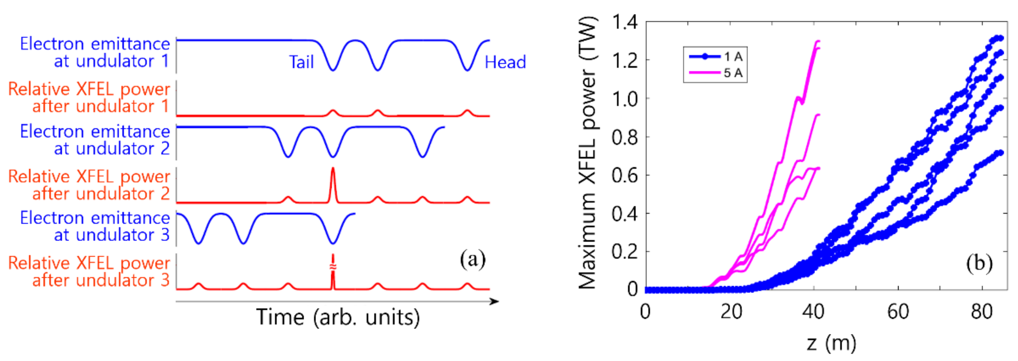
2.1. Good Emittance Region Method

A low-emittance electron beam amplifies the radiation pulse faster than a high-emittance beam. If there are two regions within an electron beam, one with high emittance and the other with low emittance, the radiation will grow in the low emittance region faster than in the high emittance region. This means that we can generate a FEL pulse with a duration shorter than the electron pulse. This process was utilized to devise the idea of generating a TW-as XFEL pulse without a laser for modulating the electron beam energy [38]. By using a slotted foil in a bunch compressor, the emittance of the electron beam can be deteriorated locally. If there are many slots in the foil with an irregular spacing, the emittance of the electron after passing through the foil is modulated as shown in Figure 1a. Only the electrons in the good emittance region (GER) will contribute to the radiation process. In the first undulator unit, we can obtain several radiation pulses spaced exactly the same as in the GER. By using an electron delay unit, we can delay the electron beam to match the last radiation pulse—called the “target radiation pulse” (TRP)—to the second-last GER. Notably, the exact meaning of TRP is different from proposal to proposal, which will be described in the following sections. In this delay process, the other radiation pulses cannot access a GER because the spacing is not regular. Repeating this process, we can amplify the TRP to the end. The other radiation pulses do not have chances for further amplification. From this method, we can obtain ~1 TW power for both 0.1 nm and 0.5 nm X-ray cases, as shown in Figure 1b for Swiss-FEL parameters, in which the beam energy was 5.8 GeV. The pulse length was about 222 ± 28 as for the 0.5 nm X-ray and 142 ± 37 for the 0.1 nm X-ray.
The target X-ray pulse is not inherently synchronized with any other external laser, which may be a pump or probe laser in a typical pump–probe experiment, because no laser is used in the emittance modulation process. Hence, this scheme is not suitable for typical pump-and-probe experiments. However, this scheme is suitable for experiments which need only short and high-power X-ray pulses.

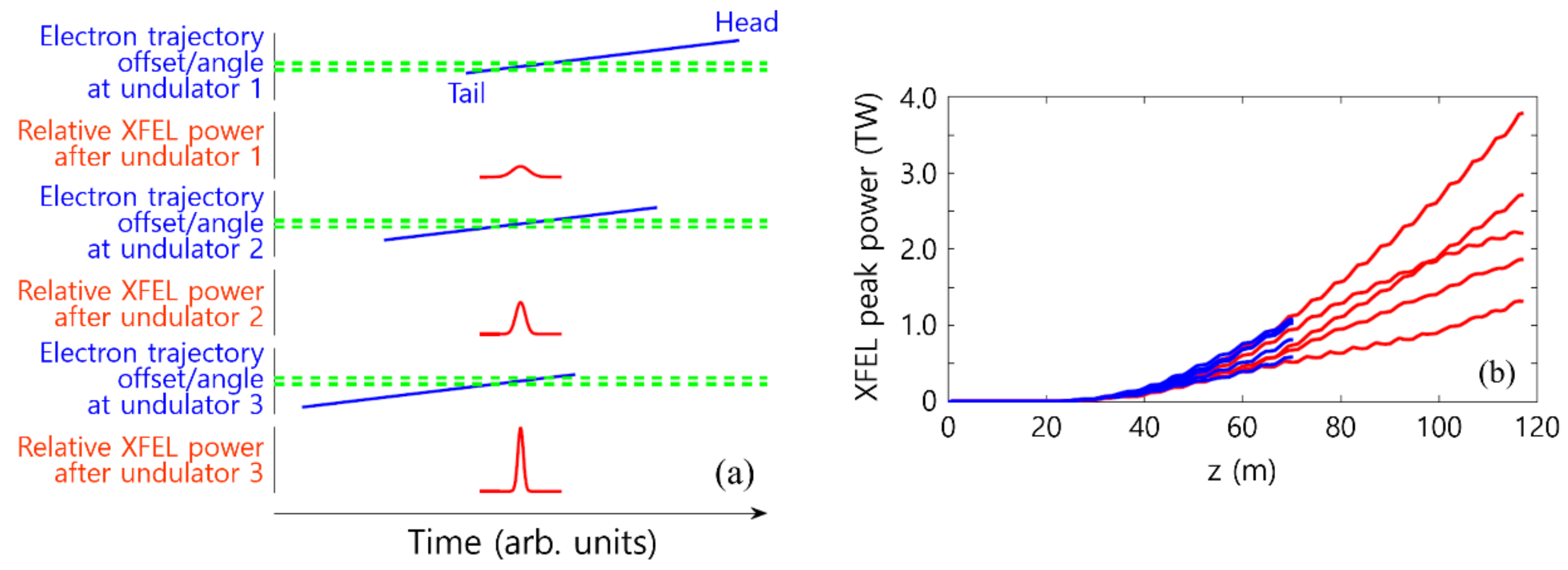
2.2. Good Trajectory Region Method

Only the electrons that stay in a straight path in an undulator—called the good trajectory region (GTR) [39]—can participate in the FEL radiation process. This also means that the FEL duration can be shorter than the electron pulse itself. Recognizing this fact, a new scheme was proposed for the TW-as XFEL pulse, in which an electron beam was tilted in an undulator entrance [39]. If we can control a part of the electron beam to stay in a straight path and the other parts not to, we can introduce the delay used in Prat et al. [38], as explained in Figure 2a, and amplify a photon pulse several times by using electron delay units between undulators. In Figure 2a, the green dashed line represents the GTR in the undulator. The blue line shows the electron beam distribution in space. We can see that the longitudinal beam distribution is tilted to GTR. We can control the tail part to stay in the GTR at the first stage of the undulator line. During the first undulator section, the electrons overlapped with the GTR will radiate. This radiation is now the target radiation pulse (TRP) (the red line represents the TRP). In the second undulator unit, the tilted electron beam is delayed to match the TRP to the middle part of the electron beam, as shown in the middle part in Figure 2a. At the third undulator unit, the electron beam is delayed further to match the TRP to the head part of the electron beam for the final amplification. There are several methods to tilt an electron beam, one of which is a transverse deflector structure [39].
By using this simple idea, it was shown that an attosecond X-ray pulse at a wavelength of 0.1 nm with a power of 2.38 ± 0.94 TW and a pulse duration of 363 ± 6 as for Swiss-FEL parameters can be obtained, as shown in Figure 2b.

3. Methods with Current Modulation

A high peak current is also helpful for increasing the power of an FEL radiation pulse. Thus, the important issue is how and how high the peak current value of an electron beam can be increased. To increase the peak current value, the electron beam needs to be compressed. In FEL facilities, a bunch compressor has been used to increase the current value from a few A to a few kA. However, if the desired peak current is larger than ~10 kA, a huge bunch compressor is necessary, which is not good for the construction of a compact FEL and its efficient operation.

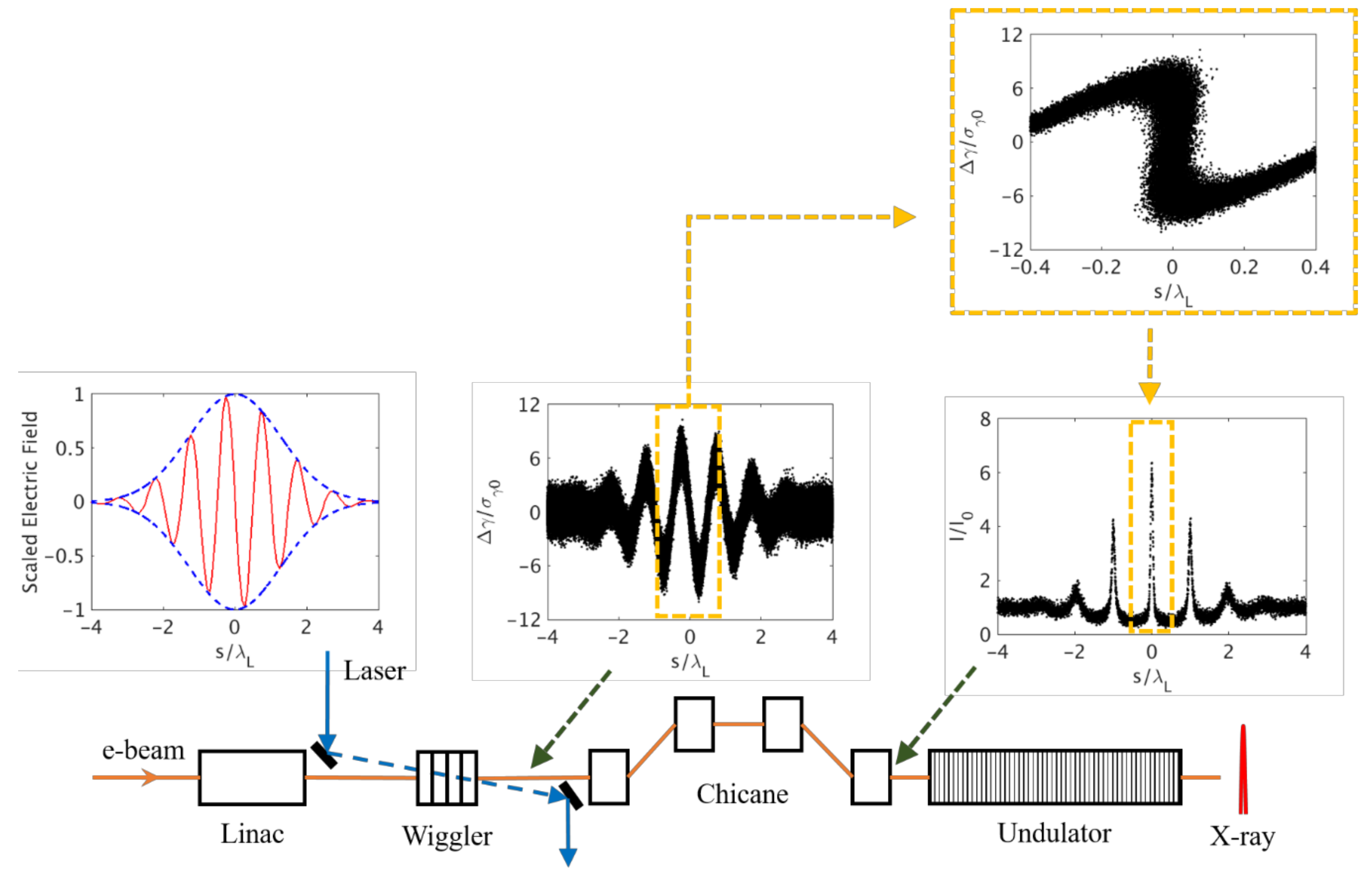
3.1. Current Modulation Method

The distance between two electrons with different energies changes in a chicane-type bunch compressor, which is composed of four dipole magnets. A high-energy electron passes the chicane with a short path length, whereas a low-energy one passes through the chicane with a longer path. This path length difference results in the density modulation of an electron beam after passing the chicane. This means that intentional energy modulation is needed for a density modulation by a chicane.
A method of modulating the electron beam energy by using a laser pulse in a wiggler has been proposed, as shown in Figure 3 [20]. A few-cycle laser pulse co-propagates with an electron beam in the wiggler. By the interaction with the electric field of a laser pulse under the magnetic field of a wiggler, some electrons gain energies and others lose energies, so that the energy modulation resembles the pattern of the electric field of the laser, as shown in the inset in the middle of Figure 3. This energy-modulated electron beam experiences density modulation when it passes through a chicane, as shown in the inset on the right of Figure 3. This simple idea initiated proposals in the accelerator physics community to realize a TW-as XFEL, as described in the following sections.

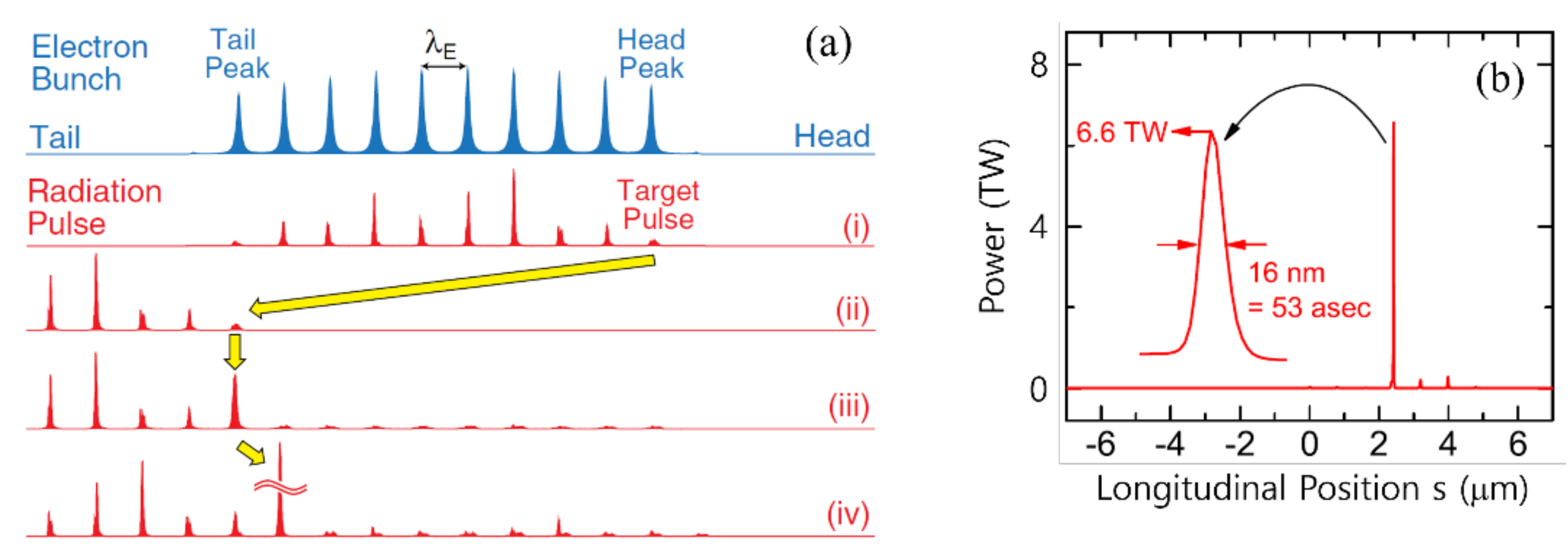
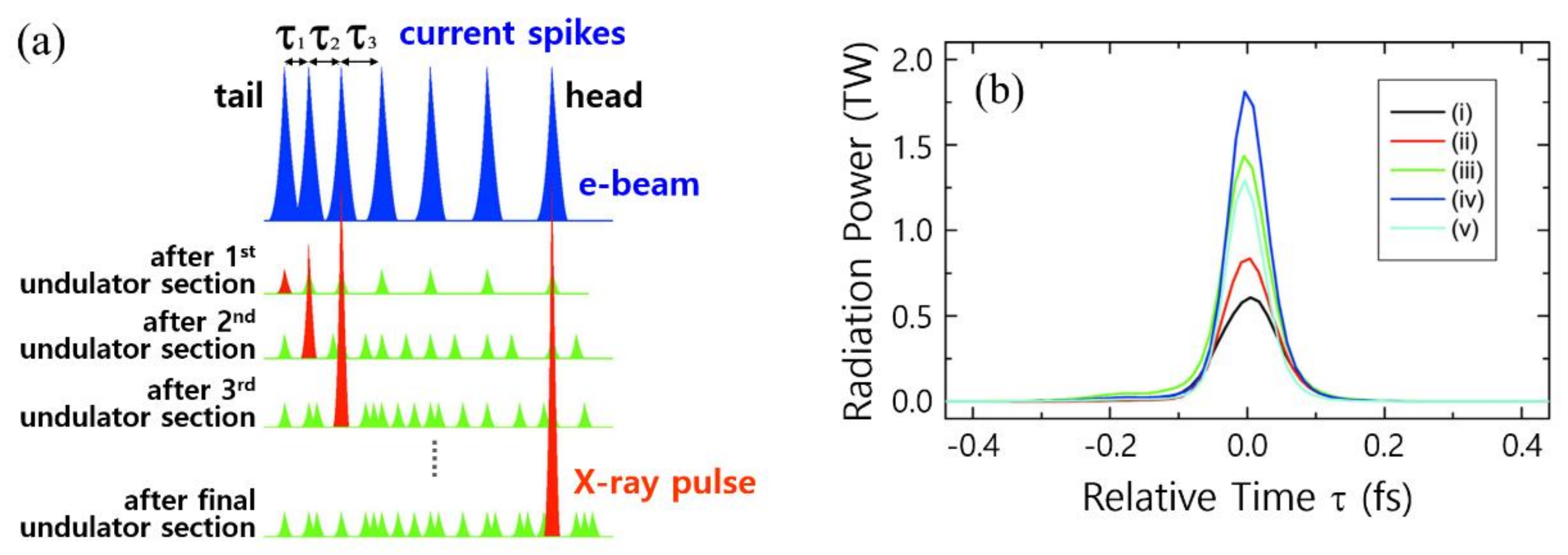
3.2. Regularly Spaced Multi-Current Spikes

The number of current spikes in the method proposed in Zholents [20] can be as many as desired. If a many-cycle laser pulse is used, multiple current spikes are generated [37]. However, if a many-current spike electron beam is sent into undulator units, each current spike independently generates radiation. If a method is devised in which all current spikes contribute only to a single radiation pulse, the radiation power will be increased, so that an over 1 TW radiation pulse can be achieved.
One idea is to introduce a large delay to the radiation pulses with respect to the current spikes at the initial stage of an undulator line [37]. X-ray pulses can be delayed by using a series of mirrors (see Kumar et al. [42] for the method of X-ray pulse delay): the first radiation pulse (“Target Pulse” in Figure 4a) is delayed to the tail current spike (“Tail Peak” in Figure 4a). This first radiation pulse is called the target radiation pulse (TRP). After a large delay, the TRP is amplified at the next undulator unit because this TRP is only matched with the tail current spike. Other radiation pulses are not matched with other current spikes. For the third amplification process, the electron beam is further delayed to match the amplified TRP with the second-last current to the tail current spike. During the radiation process in the third undulator unit, the TRP is amplified further due to the interaction with the current spike. This process is repeated until the first current spike (“Head peak” in Figure 4a) is matched to the TRP. From this method, Tanaka [37] reported that the Spring-8 Angstrom Compact free electron LAser (SACLA) XFEL can generate an X-ray pulse with a radiation power of 6.6 TW and a pulse width of 53 as at a wavelength of 0.1 nm, as shown in Figure 4b.
A drawback to this process should be pointed out. In the first step, all the current spikes radiate independently and generate many radiation pulses. In the subsequent steps, these unwanted radiation pulses may also be amplified by other current spikes because the spacing between the current spikes is the same as that between the radiation pulses. Of course, the amplification speed of the other radiation pulses is lower than the fresh current spike because the energy spread of the matched current spike is larger due to the amplification process of the TRP. However, the matched current spike still has the ability to amplify the radiation pulses. Thus, creating a truly isolated X-ray pulse using regularly-spaced current spikes is challenging. There would always be satellite radiation pulses beside the main TRP, as shown in Figure 4b, where two small (about few hundred GW) satellite radiation pulses are depicted.

3.3. Irregularly-Spaced Multi-Current Spikes

It would be nicer to have an isolated pulse without the satellite pulses shown in Figure 4b. If the current spikes can be produced with irregular spacing, the satellite radiation spikes in Tanaka [37] can, in principle, be removed. This idea was first proposed in Tanaka et al. [40] as shown in Figure 5a. Three different ideas have been proposed to generate the irregularly spaced current spikes (see Tanaka et al. [40] for details). The most important and realistic idea among these three is a chirped-laser method. If a chirped laser was used in the energy modulation process in the wiggler in Figure 3, the current spikes would be generated with irregular spacing followed by the wavelength change in a chirped laser pulse [40,41].
Simulation results with five different cases are shown in Figure 5b. The highest XFEL power with the chirped laser method reached a power of 1.8 ± 0.45 TW with a pulse duration of 62 ± 3 as.
The method proposed in Tanaka et al. [40] is a brilliant idea for solving the satellite radiation pulses that appeared in Tanaka [37]. In this proposal, there is no optical delay unit (X-ray mirrors), which increases the feasibility of this method compared to Tanaka [37]. There is still the stability issue related to the electron beam delay. The output of a power supply to control the field of the magnets in an electron delay unit may fluctuate with the voltage level; hence, there would be an error in the field amplitude, which would lead to a mismatch between the radiation pulse and the electron current spikes.

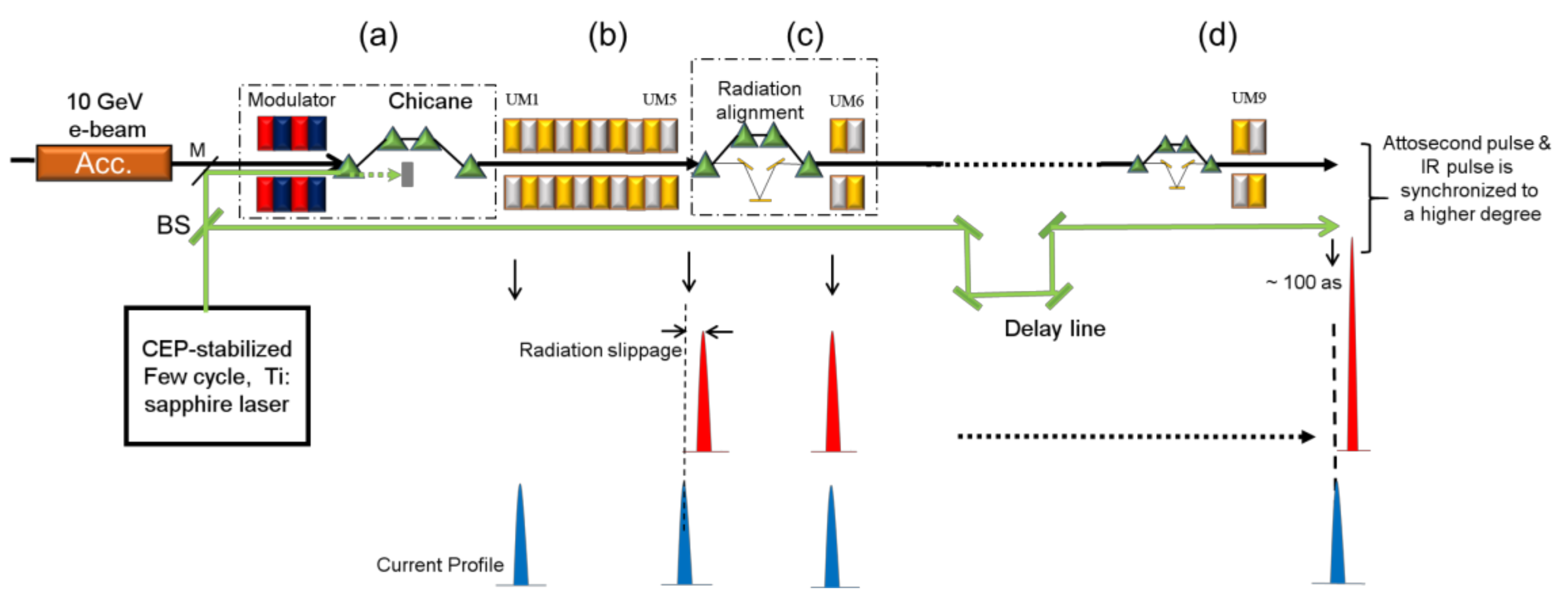
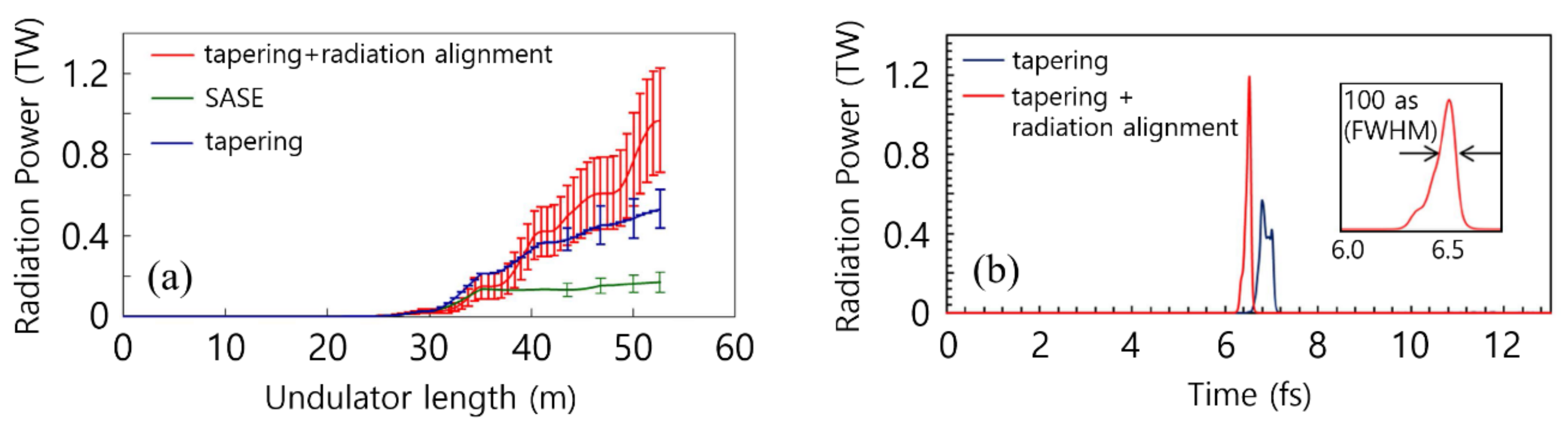
3.4. Single Current Spike I: Recycling Method

A different approach has also been undertaken. Instead of using multiple current spikes, the possibility of a single current spike for TW-as X-ray generation has been examined. Note that whereas a current of ~10 kA peak was used in the multi current spikes method, a higher peak current such as 30 kA is needed in the single current spike method.
The first idea introduced was to recycle a single current spike to amplify an X-ray pulse many times [42]. Because an X-ray pulse quickly slips out from a current spike, the current spike still shows low energy spread and good emittance. Hence, the electrons in the current spike may contribute several times to the amplification process. In other words, if an X-ray pulse is delayed again to match the same current spike, the electrons contribute further to the amplification, as shown in Figure 6.
Simulation results obtained using Elegant [46] and Genesis 1.3 code [47] are shown in Figure 7. The results with three different cases are compared. The Pohang Accelerator Laboratory X-ray Free Electron Laser (PAL-XFEL) parameters were adopted, in which the electron beam energy was 10 GeV. When an optimal tapering to the undulator gap distribution was used, a radiation power up to 1.2 TW with a pulse duration of 100 attoseconds could be obtained.
In this method, the delay of both the electron and the X-ray is needed. There would be a vibration problem in X-ray mirrors in addition to the power supply stability, as in the case of Tanaka [37]. In Tanaka [37], the X-ray delay unit was used just one time at the first stage. However, in Kumar et al. [42], the delay unit was used for every step in the amplification stage. Multiple reflections from X-ray mirrors would decrease the overall radiated power that can be achieved.

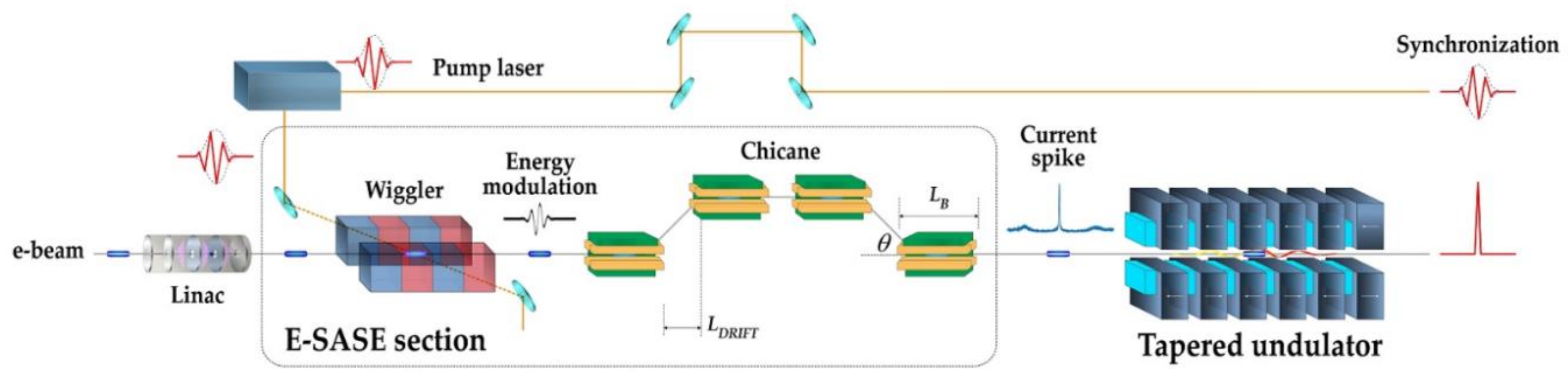
3.5. Single Current Spike II: Single Pass Method

To solve the stability problem in the above methods, the possibility of using a single current spike without electron or optical delay unit was pursued, as shown in Figure 8. To check this possibility, the following open questions should be addressed [44]: (1) How short should the current spike be? (2) How high does the current peak need to be and how can it be created? (3) How high does the power of a modulation laser need to be? (4) What is the best wavelength for a modulation laser? Shim et al. [44] discussed these questions by using the two simulation codes: Elegant [46] and Genesis 1.3 [47].
To address the first and the second questions, a series of simulations for FEL radiation growth were completed for Gaussian current spikes with different widths and heights. It was found that a current spike with a 60 nm pulse width is appropriate to obtain an X-ray pulse with a duration less than 100 as with a sufficient chance of increasing the peak power of the radiation pulse. It was also shown that the peak current of a current spike has to be higher than 35 kA to obtain TW-level radiation power. Such a current spike can be generated by the method explained in Figure 3 with an appropriate power and wavelength of a modulation laser, as shown in Figure 8. The longer the wavelength of a modulation laser, the higher the peak current of a current spike. However, the power of a modulation laser and the magnetic field of the chicane were also increased simultaneously to maintain the width of the current spike at 60 nm. These realizations provide a clue to the answers to the last two questions.
From the answers to the questions, it was concluded that a laser energy of 0.7 mJ at 2 μm wavelength is needed to generate a current spike of 37 kA peak current for the generation of a TW-level X-ray pulse with PAL-XFEL parameters. In this case, there was no extra component between the undulator units.
The simulation results are shown in Figure 9. An optimal tapering was applied to the undulator line. Due to the high peak current, the power of the FEL radiation grew very quickly in the early stage of the undulator line. In the middle part of the undulator line, the radiation pulse slipped out from the current spike. However, there was still a background current of a few kA. This small background level current still slowly amplified the radiation pulse. By this simple method, a radiation power larger than 1 TW with a pulse duration of 36 attoseconds was obtained, which is the shortest pulse expected among the schemes reviewed in this article.
This proposal is currently the simplest and the most realistic scheme. Achieving such a high peak current as 37 kA should be considered. The space charge effect will also be large. However, the investigation into the space charge effect revealed that its effect on the FEL process is minimal in the case of a high-energy beam (e.g., 10 GeV).

4. Summary and Discussion

All the results reviewed in this article are summarized in Table 1. Most schemes produced radiation power larger than 1 TW. However, with respect to the pulse duration, the current modulation methods result in a pulse shorter than 100 as in the hard X-ray region. For Prat et al. [38], the pulse duration was larger than 100 as due to the width of the good emittance region. This width was determined by the width of the slots in the foil in the bunch compressor section. For Prat et al. [39], the intersection area between the tilted electron beam and the radiation determined the pulse duration. This intersection area cannot be smaller than the transverse width of the electron beam itself.
The last row in Table 1 shows which method provides inherent synchronization between an attosecond pulse and an optical pulse. Unfortunately, the methods used by Prat et al. [38,39] did not provide the inherent synchronization. From this point of view, other methods are preferable. However, this inherent synchronization is not sufficient to ensure successful pump–probe experiments due to the timing jitter introduced by mechanical vibration. It has recently been demonstrated that at FEL experimental stations, the timing jitter generated due to the free space propagation of ~100 m and folding mirrors can be controlled with 5 fs accuracy via currently available technology [48,49]. Using a feedback loop [50] for all the mirrors (i.e., both optical and X-ray mirrors), this mechanical vibration can be suppressed and the time delay between pump (optical laser) and probe pulse (X-ray) can be controlled within 20 attoseconds RMS. An XFEL pulse might even be synchronized with current spike and with optical laser on an attosecond time-scale with the help of rapidly developing technologies in the near future.
For the realization of a TW-as XFEL with existing FEL specifications, a new undulator line needs to be constructed with delay units between the undulator sections for most proposals, except for the scheme in Shim et al. [44]. The existing undulator line may be modified so that the delay units are inserted between the undulator sections. However, there is a possibility of FEL power degradation when the undulator line is operated in normal SASE mode to generate femtosecond FEL pulses, because the delay unit will play the role of drift section between the undulator sections. A long drift section is harmful for the FEL process due to the bunching factor degradation, which is caused by the space charge force and speed difference between the electrons smearing out the microbunching in a long drift section.
There is still a technical issue that all the schemes mentioned above have not discussed seriously. When the beam is bunched at a bunch compressor in an XFEL machine, microbunching instability will occur due to the space charge effect [51] or coherent synchrotron radiation [52]. The microbunching effect on the generation of the current spikes as in Zholents [20] has to be addressed. If the microbunching effect cannot be neglected, a laser heater is needed to increase the uncorrelated energy spread to prevent the growth of the instability. The high slice energy spread of the base level current results in the high slice energy spread of the current spike. For example, if the base current of 3 kA is locally changed to a current spike of 30 kA, the slice energy spread of the current spike is also increased about 10 times. Investigations are required to address if a current spike with such a high slice energy spread can still produce TW-level power in X-ray pulses. This point should be examined in future research, and if this is problematic, new ideas need to be generated for the realization of TW-as XFELs.

Author Contributions

Writing—Original Draft Preparation, Y.W.P.; Writing—Editing, C.H.S.; Writing—Review and Supervision, D.E.K.

Funding

This research has been supported partly by Max Planck POSTECH/KOREA Research Initiative Program [2016K1A4A4A01922028] through the National Research Foundation of Korea (NRF) funded by Ministry of Science, ICT Future Planning. This research has been supported partly by the Basic Science Research Program through the National Research Foundation of Korea (NRF-2016R1D1A1B03930349).

Acknowledgments

As soon as the author (Y. W. Parc) knew of the two methods in Tanaka [37] and Prat et al. [38] at the end of 2015, the author realized that the current spikes in Tanaka [37] could also be generated with irregular spacing. The author contacted E. Prat and T. Tanaka with the idea and they published together the work Tanaka et al. [40]. The idea to use a chirped laser was proposed independently by two groups at almost the same time: D.E. Kim’s group (Korea) and T. Tanaka’s group (Japan) [40]. After that, Z. Zhao’s group (China) also published the same idea independently [41].

Conflicts of Interest

The authors declare no conflict of interest.

References

  1. Krausz, F.; Ivanov, M. Attosecond physics. Rev. Mod. Phys. 2009, 81, 163. [Google Scholar] [CrossRef]
  2. Schafer, K.; Wei, Z.; Vrakking, M. Special issue celebrating 25 years of re-collision physics. J. Phys. B At. Mol. Opt. Phys. 2017, 50, 170201. [Google Scholar] [CrossRef] [Green Version]
  3. Calegari, F.; Ayuso, D.; Trabattoni, A.; Belshaw, L.; de Camillis, S.; Anumula, S.; Frassetto, F.; Poletto, L.; Palacios, A.; Decleva, P.; et al. Ultrafast electron dynamics in phenylalanine initiated by attosecond pulses. Science 2014, 346, 336. [Google Scholar] [CrossRef] [PubMed]
  4. Dixit, G.; Vendrell, O.; Santra, R. Imaging electronic quantum motion with light. Proc. Natl. Acad. Sci. USA 2012, 109, 11636. [Google Scholar] [CrossRef] [PubMed]
  5. Dixit, G.; Slowik, J.M.; Santra, R. Theory of time-resolved nonresonant X-ray scattering for imaging ultrafast coherent electron motion. Phys. Rev. A 2014, 89, 043409. [Google Scholar] [CrossRef]
  6. Fukuzawa, H.; Son, S.-K.; Motomura, K.; Mondal, S.; Nagaya, K.; Wada, S.; Liu, X.-J.; Feifel, R.; Tachibana, T.; Ito, Y.; et al. Deep Inner-Shell Multiphoton Ionization by Intense X-Ray Free-Electron Laser Pulses. Phys. Rev. Lett. 2013, 110, 173005. [Google Scholar] [CrossRef] [PubMed] [Green Version]
  7. Ernstorfer, R.; Harb, M.; Hebeisen, C.T.; Sciaini, G.; Dartigalongue, T.; Miller, R.J.D. The Formation of Warm Dense Matter: Experimental Evidence for Electronic Bond Hardening in Gold. Science 2009, 323, 1033. [Google Scholar] [CrossRef] [PubMed]
  8. Fratalocchi, A.; Ruocco, G. Single-molecule imaging with X-Ray free-electron lasers: Dream or reality? Phys. Rev. Lett. 2011, 106, 105504. [Google Scholar] [CrossRef] [PubMed]
  9. Emma, P.; Akre, R.; Arthur, J.; Bionta, R.; Bostedt, C.; Bozek, J.; Brachmann, A.; Bucksbaum, P.; Coffee, R.; Decker, F.-J.; et al. First lasing and operation of an ångstrom-wavelength free-electron laser. Nat. Photon. 2010, 4, 641. [Google Scholar] [CrossRef]
  10. Ishikawa, T.; Aoyagi, H.; Asaka, T.; Asano, Y.; Azumi, N.; Bizen, T.; Ego, H.; Fukami, K.; Fukui, T.; Furukawa, Y.; et al. A compact X-ray free-electron laser emitting in the sub-ångström region. Nat. Photon. 2012, 6, 540. [Google Scholar] [CrossRef]
  11. Kang, H.-S.; Min, C.-K.; Heo, H.; Kim, C.; Yang, H.; Kim, G.; Nam, I.; Baek, S.Y.; Choi, H.-J.; Mun, G.; et al. Hard X-ray free-electron laser with femtosecond-scale timing jitter. Nat. Photon. 2017, 11, 708–713. [Google Scholar] [CrossRef]
  12. Altarelli, M.; Brinkmann, R.; Chergui, M.; Decking, W.; Dobson, B.; Düsterer, S.; Grübel, G.; Graeff, W.; Graafsma, H.; Hajdu, J.; et al. (Eds.) The European X-Ray Free-Electron Laser—Technical Design Report; DESY: Hamburg, Germany, 2007. [Google Scholar]
  13. Ganter, R. (Ed.) Swiss FEL—Conceptual Design Report; PSI: Villigen, Switzerland, 2010. [Google Scholar]
  14. Huang, S.; Ding, Y.; Feng, Y.; Hemsing, E.; Huang, Z.; Krzywinski, J.; Lutman, A.A.; Marinelli, A.; Maxwell, T.J.; Zhu, D. Generating Single-Spike Hard X-Ray Pulses with Nonlinear Bunch Compression in Free-Electron Lasers. Phys. Rev. Lett. 2017, 119, 154801. [Google Scholar] [CrossRef] [PubMed]
  15. Marinelli, A.; MacArthur, J.; Emma, P.; Guetg, M.; Field, C.; Kharakh, D.; Lutman, A.A.; Ding, Y.; Huang, Z. Experimental demonstration of a single-spike hard-X-ray free-electron laser starting from noise. Appl. Phys. Lett. 2017, 111, 151101. [Google Scholar] [CrossRef]
  16. Marinelli, A. Towards Attosecond Science at LCLS and LCLS-II. In Proceedings of the International Particle Accelerator Conference, Vancouver, BC, Canadam, 2 May 2018; WEXGBD3. Available online: http://ipac2018.vrws.de/talks/wexgbd3_talk.pdf (accessed on 6 September 2018).
  17. Saldin, E.L.; Schneidmiller, E.A.; Yurkov, M.V. A new technique to generate 100 GW-level attosecond X-ray pulses from the X-ray SASE FELs. Opt. Commun. 2004, 239, 161–172. [Google Scholar] [CrossRef] [Green Version]
  18. Emma, P.; Bane, K.; Cornacchia, M.; Huang, Z.; Schlarb, H.; Stupakov, G.; Walz, D. Femtosecond and Subfemtosecond X-Ray Pulses from a Self-Amplified Spontaneous-Emission–Based Free-Electron Laser. Phys. Rev. Lett. 2004, 92, 074801. [Google Scholar] [CrossRef] [PubMed]
  19. Zholents, A.A.; Fawley, W.M. Proposal for Intense Attosecond Radiation from an X-Ray Free-Electron Laser. Phys. Rev. Lett. 2004, 92, 224801. [Google Scholar] [CrossRef] [PubMed]
  20. Zholents, A.A. Method of an enhanced self-amplified spontaneous emission for X-ray free electron lasers. Phys. Rev. Spéc. Top. Accel. Beams 2005, 8, 040701. [Google Scholar] [CrossRef]
  21. Saldin, E.L.; Schneidmiller, E.A.; Yurkov, M.V. Self-amplified spontaneous emission FEL with energy-chirped electron beam and its application for generation of attosecond X-ray pulses. Phys. Rev. Spéc. Top. Accel. Beams 2006, 9, 050702. [Google Scholar] [CrossRef]
  22. Reiche, S.; Musumeci, P.; Pellegrini, C.; Rosenzweig, J.B. Development of ultra-short pulse, single coherent spike for SASE X-ray FELs. Nucl. Instrum. Methods A 2008, 593, 45–48. [Google Scholar] [CrossRef]
  23. Thompson, N.R.; McNeil, B.W.J. Mode Locking in a Free-Electron Laser Amplifier. Phys. Rev. Lett. 2008, 100, 203901. [Google Scholar] [CrossRef] [PubMed]
  24. Xiang, D.; Huang, Z.; Stupakov, G. Generation of intense attosecond X-ray pulses using ultraviolet laser induced microbunching in electron beams. Phys. Rev. Spéc. Top. Accel. Beams 2009, 12, 060701. [Google Scholar] [CrossRef]
  25. Ding, Y.; Huang, Z.; Ratner, D.; Bucksbaum, P.; Merdji, H. Generation of attosecond X-ray pulses with a multicycle two-color enhanced self-amplified spontaneous emission scheme. Phys. Rev. Spéc. Top. Accel. Beams 2009, 12, 060703. [Google Scholar] [CrossRef]
  26. Chung, S.-Y.; Yoon, M.; Kim, D.E. Generation of Attosecond X-ray and gamma-ray via Compton backscattering. Opt. Express 2009, 17, 7853–7861. [Google Scholar] [CrossRef] [PubMed]
  27. Kim, D.; Lee, H.; Chung, S.; Lee, K. Attosecond keV X-ray pulses driven by Thomson scattering in a tight focus regime. New J. Phys. 2009, 11, 063050. [Google Scholar] [CrossRef]
  28. Chen, G.; Kim, B.; Ahn, B.; Kim, D.E. Pressure dependence of argon cluster size for different nozzle geometries. J. Appl. Phys. 2009, 106, 053507. [Google Scholar] [CrossRef] [Green Version]
  29. Hwang, S.W.; Lee, H.J.; Chung, S.Y.; Kim, D.-E. X-ray Radiation Emitted from the Betatron Oscillation of Electrons in Laser Wakefields. J. Korean Phys. Soc. 2010, 56, 309–314. [Google Scholar]
  30. Lee, K.; Chung, S.Y.; Park, S.H.; Jeong, Y.U.; Kim, D. Effects of high-order fields of a tightly focused laser pulse on relativistic nonlinear Thomson scattered radiation by a relativistic electron. Europhys. Lett. 2010, 89, 64006. [Google Scholar] [CrossRef] [Green Version]
  31. Kumar, S.; Kang, H.-S.; Kim, D.E. Generation of isolated single attosecond hard X-ray pulse in enhanced self-amplified spontaneous emission scheme. Opt. Express 2011, 19, 7537–7545. [Google Scholar] [CrossRef] [PubMed]
  32. Chung, S.-Y.; Lee, H.J.; Lee, K.; Kim, D.E. Generation of a few femtosecond keV X-ray pulse via interaction of a tightly focused laser co-propagating with a relativistic electron bunch. Phys. Rev. Spéc. Top. Accel. Beams 2011, 14, 060705. [Google Scholar] [CrossRef]
  33. Kumar, S.; Kang, H.-S.; Kim, D.-E. For the generation of an intense isolated pulse in hard X-ray region using X-ray free electron laser. Laser Part. Beams 2012, 30, 397–406. [Google Scholar] [CrossRef]
  34. Kumar, S.; Kang, H.-S.; Kim, D.-E. Attosecond Hard X-ray Free Electron Laser. Appl. Sci. 2013, 3, 251. [Google Scholar] [CrossRef]
  35. Kumar, S.; Kang, H.-S.; Kim, D.E. The effect of a radio-frequency phase of accelerating columns on the attosecond ESASE scheme. J. Phys. B At. Mol. Opt. Phys. 2013, 46, 164004. [Google Scholar] [CrossRef]
  36. Kumar, S.; Kim, D.-E.; Kang, H.-S. Tunable THz radiation generation using density modulation of a relativistic electron beam. Nucl. Instrum. Methods A 2013, 729, 19–24. [Google Scholar] [CrossRef]
  37. Tanaka, T. Proposal for a Pulse-Compression Scheme in X-Ray Free-Electron Lasers to Generate a Multiterawatt, Attosecond X-Ray Pulse. Phys. Rev. Lett. 2013, 110, 084801. [Google Scholar] [CrossRef] [PubMed]
  38. Prat, E.; Reiche, S. Simple Method to Generate Terawatt-Attosecond X-Ray Free-Electron-Laser Pulses. Phys. Rev. Lett. 2015, 114, 244801. [Google Scholar] [CrossRef] [PubMed]
  39. Prat, E.; Löhl, F.; Reiche, S. Efficient generation of short and high-power X-ray free-electron-laser pulses based on superradiance with a transversely tilted beam. Phys. Rev. Spéc. Top. Accel. Beams 2015, 18, 100701. [Google Scholar] [CrossRef]
  40. Tanaka, T.; Parc, Y.W.; Kida, Y.; Kinjo, R.; Shim, C.H.; Ko, I.S.; Kim, B.; Kim, D.E.; Prat, E. Using irregularly spaced current peaks to generate an isolated attosecond X-ray pulse in free-electron lasers. J. Synchrotron Rad. 2016, 23, 1273. [Google Scholar] [CrossRef] [PubMed]
  41. Wang, Z.; Feng, C.; Zhao, Z. Generating isolated terawatt-attosecond X-ray pulses via a chirped-laser-enhanced high-gain free-electron laser. Phys. Rev. Accel. Beams 2017, 20, 040701. [Google Scholar] [CrossRef]
  42. Kumar, S.; Parc, Y.W.; Landsman, A.S.; Kim, D.E. Temporally-coherent terawatt attosecond XFEL synchronized with a few cycle laser. Sci. Rep. 2016, 6, 37700. [Google Scholar] [CrossRef] [PubMed] [Green Version]
  43. Kumar, S.; Landsman, A.S.; Kim, D.E. Terawatt-Isolated Attosecond X-ray Pulse Using a Tapered X-ray Free Electron Laser. Appl. Sci. 2017, 7, 614. [Google Scholar] [CrossRef]
  44. Shim, C.H.; Parc, Y.W.; Kumar, S.; Ko, I.S.; Kim, D.E. Isolated terawatt attosecond hard X-ray pulse generated from single current spike. Sci. Rep. 2018, 8, 7463. [Google Scholar] [CrossRef] [PubMed]
  45. Serkez, S.; Geloni, G.; Tomin, S.; Feng, G.; Gryzlova, E.V.; Grum-Grzhimailo, A.N.; Meyer, M. Overview of options for generating high-brightness attosecond X-ray pulses at free-electron lasers and applications at the European XFEL. J. Opt. 2018, 20, 024005. [Google Scholar] [CrossRef]
  46. Borland, M. Elegant: A Flexible SDDS-Compliant Code for Accelerator Simulation. Adv. Photon Source 2000. [Google Scholar] [CrossRef]
  47. Reiche, S. GENESIS 1.3: A fully 3D time-dependent FEL simulation code. Nucl. Instrum. Methods A 1999, 429, 243. [Google Scholar] [CrossRef]
  48. Schulz, S.; Grguraš, I.; Behrens, C.; Bromberger, H.; Costello, J.T.; Czwalinna, M.K.; Felber, M.; Hoffmann, M.C.; Ilchen, M.; Liu, H.Y.; et al. Femtosecond all-optical synchronization of an X-ray free-electron laser. Nat. Commun. 2015, 6, 5938. [Google Scholar] [CrossRef] [PubMed] [Green Version]
  49. Cinquegrana, P.; Cleva, S.; Demidovich, A.; Gaio, G.; Ivanov, R.; Kurdi, G.; Nikolov, I.; Sigalotti, P.; Danailov, M.B. Optical beam transport to a remote location for low jitter pump-probe experiments with a free electron laser. Phys. Rev. Spéc. Top. Accel. Beams 2014, 17, 040702. [Google Scholar] [CrossRef]
  50. Chini, M.; Mashiko, H.; Wang, H.; Chen, S.; Yun, C.; Scott, S.; Gilbertson, S.; Chang, Z. Delay control in attosecond pump-probe experiments. Opt. Express 2009, 17, 21459–21464. [Google Scholar] [CrossRef] [PubMed]
  51. Saldin, E.L.; Schneidmiller, E.A.; Yurkov, M.V. On the coherent radiation of an electron bunch moving in an arc of a circle. Nucl. Instrum. Methods A 1997, 398, 373. [Google Scholar] [CrossRef]
  52. Borland, M.; Chae, Y.C.; Emma, P.; Lewellen, J.W.; Bharadwaj, V.; Fawley, W.M.; Krejcik, P.; Limborg, C.; Milton, S.Y.; Nuhn, H.-D.; et al. Start-to-end simulation of self-amplified spontaneous emission free electron lasers from the gun through the undulator. Nucl. Instrum. Methods A 2002, 483, 268. [Google Scholar] [CrossRef]
Figure 1. (a) Schematic diagram for the good emittance region (GER) method in Prat et al. [38]. The first blue line on the top: GERs have different spaces with respect to the neighborhood GER. The first red line: the radiation pulses generated from the electron beam in the first undulator. The last red peak in the “tail” part is our target radiation pulse (TRP). The second blue line: the electron beam is delayed to match the second GER to the TRP. The second red line: the TRP is amplified in the second undulator. The third blue line: the electron beam is delayed further to match the third GER to the TRP. The third red line: the TRP is amplified further by the third GER in the third undulator unit. (b) Simulation results: “1 A” (“5 A”) means a wavelength of 0.1 nm (0.5 nm). Reproduced with permission from Prat et al. [38]. XFEL: X-ray free electron laser.
Applsci 08 01588 g001
Figure 2. (a) Schematic drawing for the tilting method in Prat et al. [39] for amplification. The blue solid line represents the longitudinal direction of an electron beam. The green dashed line shows the good trajectory region (GTR). The red lines show the amplification process of the TRP. (b) Simulation results for radiated power in the tilt method. The different colors in (b) represent the different offset of the electron beam at the entrance of the undulator. See Prat et al. [39] for details. Reproduced from Prat et al. [39] with permission.
Applsci 08 01588 g002
Figure 3. Current modulation method introduced in Zholents [20]. The blue arrows represent the propagation of a laser pulse. The electric field of a few-cycle laser is shown in the inset (left part). The energy modulation of the electron beam through a wiggler is shown in the inset (the middle part). The shape of energy modulation is almost the same as the profile of the few-cycle laser field. The chicane turns the energy modulation into density modulation, as shown in the inset (right part). The number of current peaks is the same as the number of cycles of the laser field. The peak value of a current spike is determined by the amplitude of the energy modulation.
Applsci 08 01588 g003
Figure 4. (a) Amplification process of the TRP (“Target Pulse” in the figure) by using regularly-spaced current spikes. The electron bunch has multiple current spikes with the same spacing (top). (i) Multiple radiation pulses are generated from the first undulator unit. (ii) The radiation pulses are delayed to match the target pulse to the tail peak. (iii) In the second undulator unit, only the target pulse is amplified. (iv) We now delay one more time the electron bunch to match the amplified target pulse to the second -last current spike (just before the tail peak). This step is repeated. (b) A result of this process: a strong main radiation pulse with side peaks. Reproduced from Tanaka [37] with permission.
Applsci 08 01588 g004
Figure 5. (a) Irregularly-spaced current spikes. The electron bunch has multiple current spikes with different spacing (top). Multiple radiation pulses (green small spikes) are generated from the first undulator unit (second line). The red colored line is now our TRP. The radiation pulses are delayed to match the TRP to the second-last current (third line). In the second undulator unit, only the TRP is matched with a current spike, and is amplified. The electron bunch is then further delayed to match the amplified TRP to the third-last current spike (fourth line). This process is repeated to the end (bottom). (b) Simulation results with four different conditions. (i) The original method used in Tanaka [37]. (ii) Linearly tapered wiggler (the field between each magnet pole is changed linearly along the beam propagation direction) in Figure 3 with a 1.5 cycle laser pulse. (iii) Well-type tapered wiggler n Figure 3 with a 1.5 cycle laser pulse. (iv) Chirped laser method which shows highest radiation power. (v) Laser pulse stacking method (a laser pulse is divided to several pulses and is summed again with different arrival times, such as τ 1 ,   τ 2 , as shown in the top part of Figure 5a). See Tanaka et al. [40] for the details. Reproduced from Tanaka et al. [40] with permission.
Applsci 08 01588 g005
Figure 6. Single current spike method-recycling. (a) An electron beam is modulated by a single-cycle laser pulse to have a single current spike; (b) In the first long undulator unit, a single radiation spike (red peak) is generated from a single current spike (blue peak); (c) With a delay unit which is composed of magnets and X-ray mirrors, the radiation spike can be rematched to the current spike. See Kumar at al. [42] for more details of the X-ray pulse delay shown in (c); (d) This step is repeated to the end. Reproduced from Kumar et al. [42] with permission.
Applsci 08 01588 g006
Figure 7. Simulation results with single current spike method-recycle in Figure 6. (a) The radiation power growth in the undulator line. SASE (green line) means the simulation result without any tapering in the undulator line. In the tapering case (blue line), an optimal tapering is provided in the undulator line without the recycle of a single current spike. The result shows a radiation power of only 0.55 TW with a pulse duration of 300 attoseconds. In the tapering with radiation alignment case (red line), the method in Figure 6 is applied. With the recycle of a single current spike, we can obtain radiation power larger than 1 TW. (b) The temporal profile of the FEL radiation. The main peak (red line) is expanded in the inset (the red line in the right part with two arrows) to show the temporal structure. Reproduced from Kumar et al. [42] with permission. FWHM: full width at half maximum.
Applsci 08 01588 g007
Figure 8. Single current-spike method-single pass. An electron beam is modulated in the E-SASE section (which is composed of a wiggler and a chicane-type magnet compressor) by the method explained in Zholents [20]. There is no delay unit in the undulator line. Reproduced from Shim et al. [44] with permission.
Applsci 08 01588 g008
Figure 9. Simulation results with single current-spike method-single pass in Figure 8. (a) FEL power growth in the undulator line; (b) Temporal profile for five different seeds in the simulation. Blue line represents a specific case among the five different cases. Reproduced from Shim et al. [44] with permission.
Applsci 08 01588 g009
Table 1. Comparison between the main parameters of the methods reviewed.
Reference
Parameter[38][39][37][40][42][44]
Photon energy (keV)12.412.4107.712.412.4
FEL power (TW)0.952.386.61.81.21.5
Pulse duration (as)142363536210036
Beam energy (GeV)5.85.8871010
Peak current (kA)NANA12–1853335
Inherent synchronizationNoNoYesYesYesYes

