1. Introduction
In the past few years, scientists have faced a consequential issue of thermal efficiency in different engineering and industrial applications. Technological advances, like high speed microelectronics, chemical synthesis, transportation, optical, microfluidics, microsystems including mechanical and electrical components bears high thermal loads. The cooling of these devices is a major concern in these days. Traditionally, the rate of heat transfer is increased by increasing the area available for heat exchange. Another way is to use a thermally efficient fluid, which is usually dispersed the nano-sized structures within the conventional heat transfer fluids (fluids bearing poor thermal properties), like water, propylene glycol, ethylene glycol, etc. [
1]. The pioneer behind the discovery of these thermally efficient fluids, called ‘nanofluids’, was Choi [
2,
3]. This discovery further opens the door to a new research era. Many experimentalists would opt for this idea and as a result, several subsequent models have been successfully proposed. Maxwell [
4] took a first step and suggested a model to analyze the effective thermal conductivity of nanofluids. This model involves the nanoparticles concentration and the thermal conductivity of the base fluid and nanoparticles. Besides, it only takes the spherical inclusions of nanoparticles. To overcome this deficiency, Hamilton and crosser [
5] proposed a model which is applicable for non-spherical shaped nanoparticles. More studies in this area introduce a variety of models which examined the effects of nanoparticles type [
6,
7,
8], particle shapes [
9] and particles size [
10,
11] etc. Moreover, various heat transfer mechanisms including Brownian movement of particles [
12], particles agglomeration [
13,
14] and liquid layering [
15] would also gain the attention of many scientists.
Even though nanofluids have a lot of potential to meet the growing thirst of thermal efficiency, still scientists are eagerly looking for different varieties of fluids. Hybrid nanofluids are an advanced type of nanofluids, which exhibit a remarkable thermal efficiency as compared to nanofluids. These fluids came into existence by dispersing two or more kinds of tiny particles within the base fluid or composite nanostructures in a base fluid. This implies a homogeneous mixture possessing physicochemical properties of various substances that can hardly be imagined to exist in an individual substance [
16].
Hybrid nanofluids play an active role in a wide range of heat transfer applications such as electronic cooling, automobile radiators, generator cooling, nuclear system cooling, coolant in machining, lubrication, welding, solar heating, thermal storage, heating and cooling in buildings, biomedical, drug reduction, refrigeration and defense etc. At the industrial level, there are positive features like chemical stability and high thermal efficiency, which enables them to perform efficiently as compared to nanofluids.
In the last few decades, many experimental studies have been conducted to explore the properties of hybrid nanofluids. Suresh et al. [
17] employed the two-step method to study the synthesis of hybrid Al
2O
3–Cu/water nanofluids. The rate of heat transfer influenced by H
2O-based Al
2O
3–Cu hybrid nanofluids was examined by Suresh et al. [
18]. Momin [
19] experimentally investigates the laminar flow of a hybrid nanofluid along with mixed convection inside an inclined tube. Later on, the magnetohydrodynamic (MHD) flow of a hybrid Al
2O
3–Cu/water nanofluid over a permeable expanding sheet along with suction has been numerically considered by Devi and Devi [
20]. Recently, to analyze the entropy generation, Das et al. [
21] takes into account the magnetohydrodynamic Cu–Al
2O
3/water-based hybrid nanofluid flow between porous walls. Olatundun and Makinde [
22] analyze the Blasius hybrid nanofluid flow over a heated surface combined with convection. Moreover, Hayat and Nadeem [
23] utilize the water-based Ag–CuO hybrid nanofluid in order to enhance the heat transfer.
Many real-life situations like the respiratory system, aerospace engineering, industrial cleansing systems, coolant circulation and inter-body fluid transportation depend upon the flows between deformable channels. In 1953, the pioneer who initiated a mathematical model for the description of fluid behavior inside a rectangular channel, was Berman [
24]. Uchida and Aoki [
25] took a first step towards the study of viscid flow within a permeable squeezing pipe. Several laminar flow problems inside a porous dilating channel was simultaneously investigated by Majdalani et al. [
26], Dauenhauer and Majdalani [
27], Majdalani and Zhou [
28] and Ganji et al. [
29]. Mohyud-din et al. [
30] analyzed the simultaneous behavior of chemical reaction and heat transfer for the viscid fluid flow inside a deformable porous channel. Ahmed et al. [
31] numerically investigates the CNT/H
2O-based nanofluid flow along with heat transfer through an asymmetric channel whose walls are capable of expanding and contracting in height.
In a survey of the literature, it has been found that no systematic research has yet been conducted to investigate the rheological and thermal characteristics of Cu–Al2O3/water-based hybrid nanofluid along with the influence of particle shapes inside a channel whose walls are permeable and have a capability of dilating and squeezing. Therefore, we present this article to analyze the influence of nanocomposite shape factor on the flow and heat transfer behavior of Cu–Al2O3/water-based hybrid nanofluid between permeable walls of a rectangular channel. As the resulting flow model is quite complicated in nature, therefore exact solution is least likely. To overcome this difficulty, the Runge–Kutta–Fehlberg scheme (RKF) has been employed to obtain a numerical solution. Subsequently, the results against the embedded parameters has been presented in the graphical form along with a quantitative discussion.
2. Formulation of the Governing Equations
Consider the time dependent, laminar, viscid and incompressible water-based Cu–Al
2O
3 hybrid nanofluid flow, inside a permeable rectangular channel, whose length is assumed to be infinite. To achieve the configuration of Cu–Al
2O
3/water hybrid nanofluid, initially, the spherical shaped tiny particles of Al
2O
3 with solid volume fraction of about 0.1 vol (which is restricted for the present flow problem) has been suspended in the base fluid H
2O to form a Al
2O
3-nanofluid and finally the composition of Cu–Al
2O
3/H
2O hybrid nanofluid has been accomplished by employing copper Cu nanoparticles with variable volume fraction. Furthermore, the channel is assumed to be very small in height against its width and length.
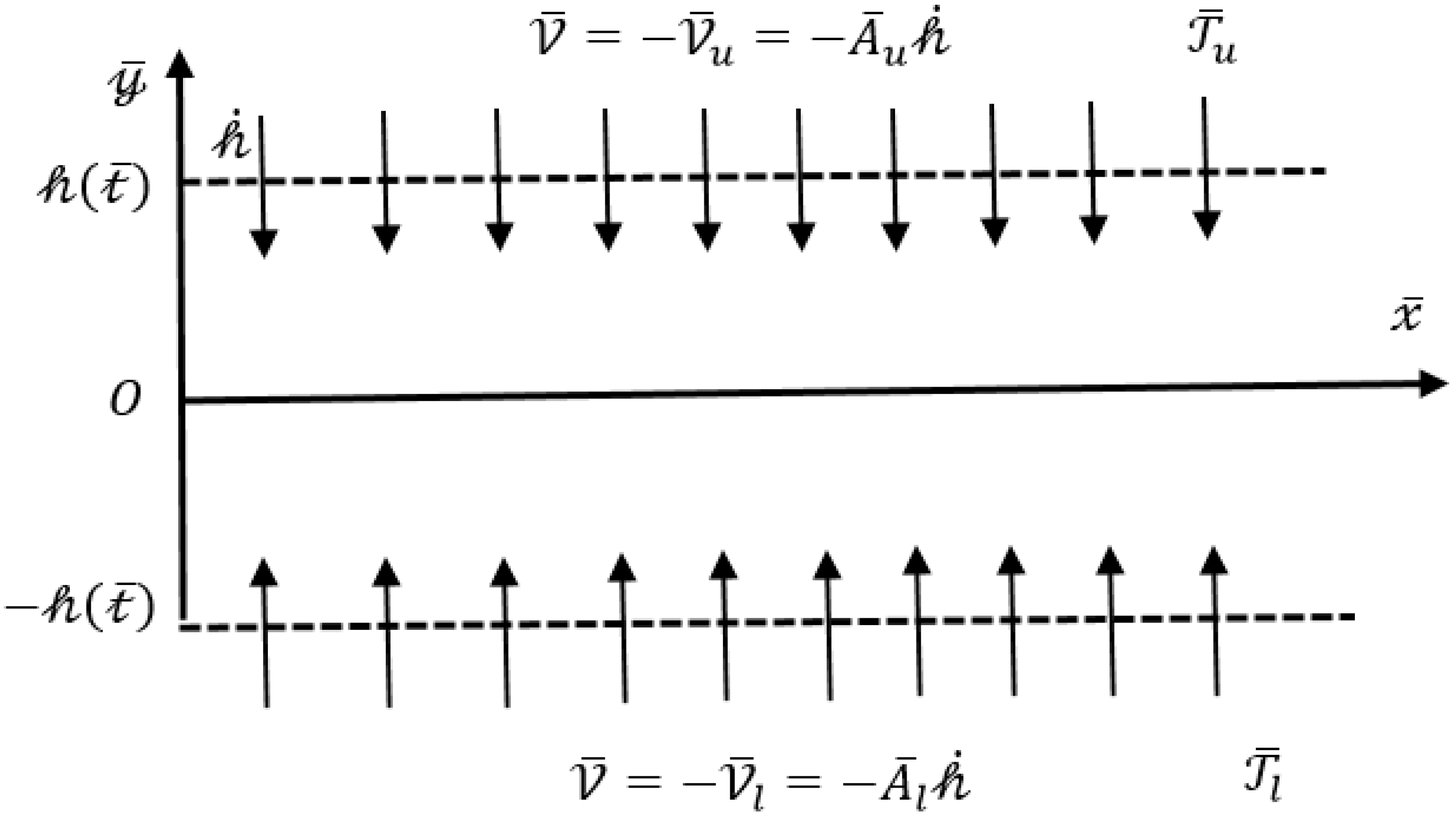
Figure 1 displays the cross-sectional view of the channel for the present flow problem.
It is further assumed that the channel is half opened. The leading end is shielded by an impermeable flexible membrane, while the other end is left opened so that the fluid can easily flow through it. The permeable walls permit the fluid to enter or leave the channel during the successive dilations or contraction of the channel in height. In the beginning, the channel’s height is assumed to be .
The top and bottom walls experience a parting or embracing motion at a uniform time dependent rate
. The origin has been considered as the center of the channel which is displayed in
Figure 1.
signifies the temperature with the assumption that
. The subscripts
and
respectively symbolize the traits of bottom and top walls. By keeping the above-mentioned assumptions in view, the following mathematical forms expresses the governing equations for mass, momentum and energy, which are given as:
where, the velocity components in the horizontal and vertical directions are symbolized by
and
, respectively
stands for the dimensional pressure. Furthermore,
represents the viscosity of the hybrid nanofluid. In literature, several theoretical models including the effects of nanoparticle material [
32], particle size [
33] and liquid layering [
34,
35] have been available in order to estimate the viscosity of nanofluids. In 1952, Brinkman [
36] proposed a correlation for the effective viscosity of the nanofluid which typically involves the viscosity of the host fluid and the nanoparticles concentration. Besides, this expression is reliable for dilute solutions. In case of hybrid nanofluids, this expression would take the following mathematical form [
37]:
Similarly, by taking the mixture principle into account, the effective density
[
37] proposed by Pak and Cho [
38] and the volumetric heat capacity
[
37,
39] for
hybrid nanofluid can be estimated via Equations (6) and (7), which is given as under:
Furthermore, among various thermo-mechanical properties, the thermal conductivity is the one that plays a key role in transferring the heat. Hamilton and Crosser [
5] proposed an efficient model for thermal conductivity which is applicable for different shapes of nanocomposites. In context to hybrid nanofluids, the expression is defined as [
37]:
where,
In the above relations,
and
represents the shape factor of Cu and Al
2O
3 nano-sized particles respectively.
is the thermal conductivity of the Al
2O
3-nanofluid, while the thermal conductivity of base fluid H
2O is expressed by
. The thermal conductivity of Al
2O
3 and Cu are respectively denoted by
and
. Furthermore,
stands for the volume fraction of Al
2O
3 nanoparticles while the solid volume fraction for Cu nanoparticles are represented by
. The base fluid viscosity, density and specific heat are simultaneously symbolized by
and
.
and
denotes the densities of Al
2O
3 and Cu respectively. At constant pressure,
and
respectively indicates the specific heat of Al
2O
3 and Cu nanoparticles.
Table 1 has been decorated for the thermo-physical properties of base fluid H
2O and nanoparticles Al
2O
3 and Cu.
The suitable boundary conditions for the present flow problem are specified as:
Here,
depicts the absolute suction or injection velocity of the fluid at the bottom wall of the channel which is equivalent to the product of the permeability factor
and the wall velocity
. The same for the upper wall is denoted by
, where the permeability of the upper wall is represented by
[
27]. It is important to mention that these velocities are assumed to be independent of the position at the walls and they are also different from each other [
25,
26,
27,
28].
Keeping in view the concept of mass conservation, the subsequent transforms has been established:
where, the suffices
indicates
. Using Equation (11) and by eliminating pressure terms, Equations (1)–(3) reduces to a following single equation:
Over here, the rate with which wall deforms is symbolized by . For stretching channel, possesses positive values.
The suggestions presented by [
40], lead us to a time-based similarity solution which can be established on the basis of the fact that
is uniform in time. Consequently, the term
has been eliminated. Moreover, the values of
can be settled down by considering the prior height of the channel along with dilation rate.
The transformed set of auxiliary conditions (Equation (10)) related to the velocity is defined as
where, the permeation Reynolds number at the bottom wall is indicated by
, while
denotes the permeation Reynolds number at the top wall. They possesses positive values for the injection case.
The following set of scale variables has been used for converting the velocity and energy equations (Equations (4) and (12)) into a dimensionless form as:
which in result, gives us the following set of ordinary differential equations:
where,
The reduced dimensionless form of boundary conditions is defined as:
where,
is the symbol for permeability parameter. Moreover,
denotes Prandtl number.
The local heat transfer rate (i.e., local Nusselt number) is defined by:
Subsequently, the set of scale variables converts the above equation into dimensionless rate of heat transfer both at the bottom and top wall, which is then expressed by the following relations:
It is pertinent to mention here that, if , then hybrid nanofluid is no longer be preserved and converted to the regular fluid (water). When , then water-based Al2O3 nanofluid has been achieved. For Cu–Al2O3/H2O-based hybrid nanofluid, the relation must be satisfied.
4. Results and Discussion
The prime focus of this section is to graphically demystify the obtained results. The salient features of the flow and heat transfer of a Cu–Al2O3/H2O hybrid nanofluid have been examined in a rectangular channel whose walls are permeable and have a capability of dilating or squeezing. Moreover, the investigations have been carried out to see the influence of various embedded parameters such as solid volume fraction , deformation parameter , permeation Reynold number and permeability parameter on the velocity as well as temperature profiles.
Table 1 focused on the thermo-physical properties of base fluid and nanoparticles. The model employed for the effective thermal conductivity of Cu–Al
2O
3/H
2O hybrid nanofluid has an embedded parameter ‘
’ (where
denotes the sphericity of different nanocomposites), which varies for different shapes of nanocomposites. The numerical values related to the shape factor for different non-spherical tiny sized particles can be found in
Table 2. Platelet-, cylinder- and brick- shaped nanocomposites have been under consideration. Furthermore, it is important to mention that the spherical shaped Al
2O
3 nanoparticles have been dispersed in the base fluid, therefore
. Since the hybrid nanofluid under consideration is water-based, therefore the numerical value for Prandtl number has been restricted to 6.135.
To visualize the velocity behavior,
Figure 2,
Figure 3,
Figure 4,
Figure 5,
Figure 6,
Figure 7,
Figure 8 and
Figure 9 are designed. Each figure holds an inset picture which give us the magnified view of the parameter’s behavior within the regions
(leftward) and
(rightward) unless specified otherwise.
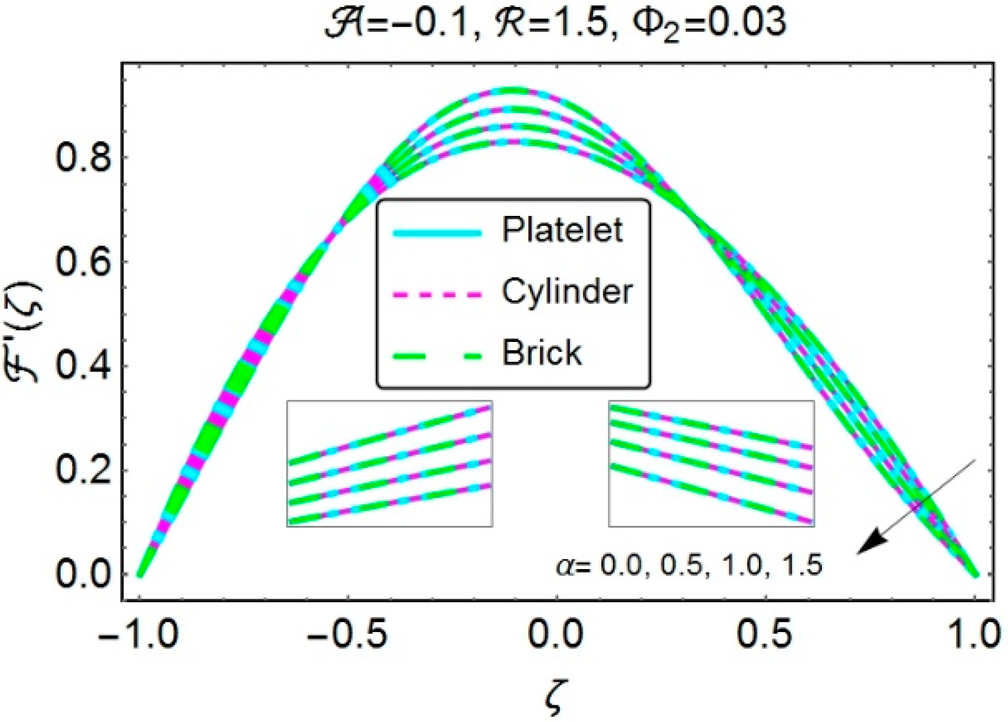
Figure 2 and
Figure 3 simultaneously depict the cases when the velocity behavior is influenced by channel’s contraction along with suction and injection. In the first case, one can clearly observe a speedy flow nearby the wall for growing absolute values of
. The reason behind is the wall’s contraction which suppresses the adjacent layers of fluid and force them to move forward. Suction also plays an important role to enhance the fluid’s velocity nearby the wall. Instead, a retardation in the flow has been detected far away from the walls. Subsequently,
Figure 3 deals with the contraction along with injection. Again, one can observe a clear enhancement in fluid’s velocity close to the wall with the increased absolute values of
, which means that the contracted walls again play a key role to speed up the flow nearby the wall. Moreover, no considerable change has been detected in the velocity profile for various shapes of nanocomposites.
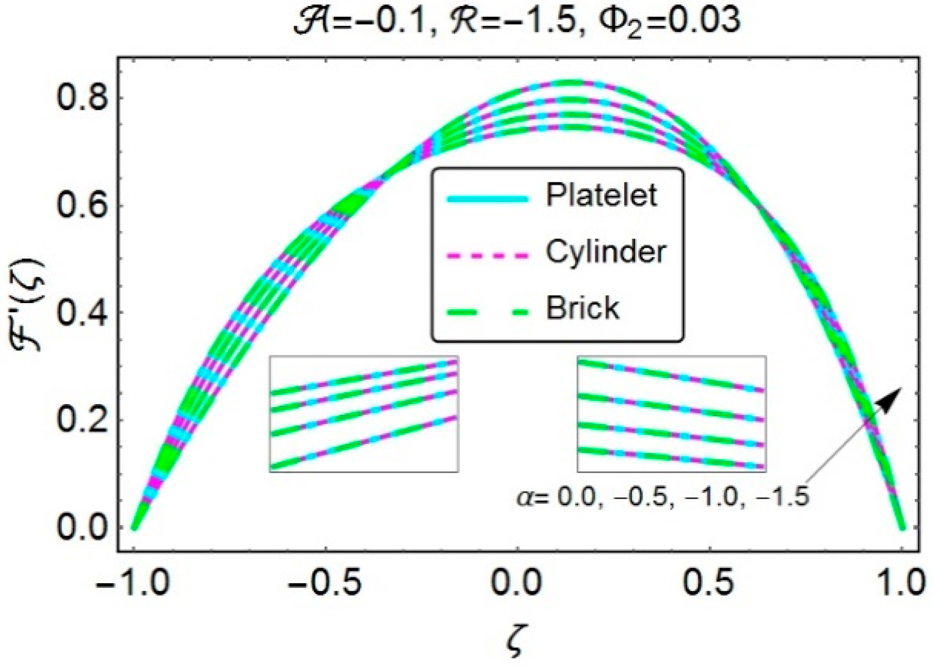
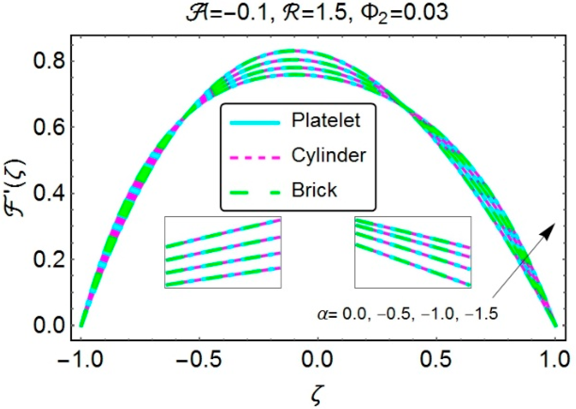
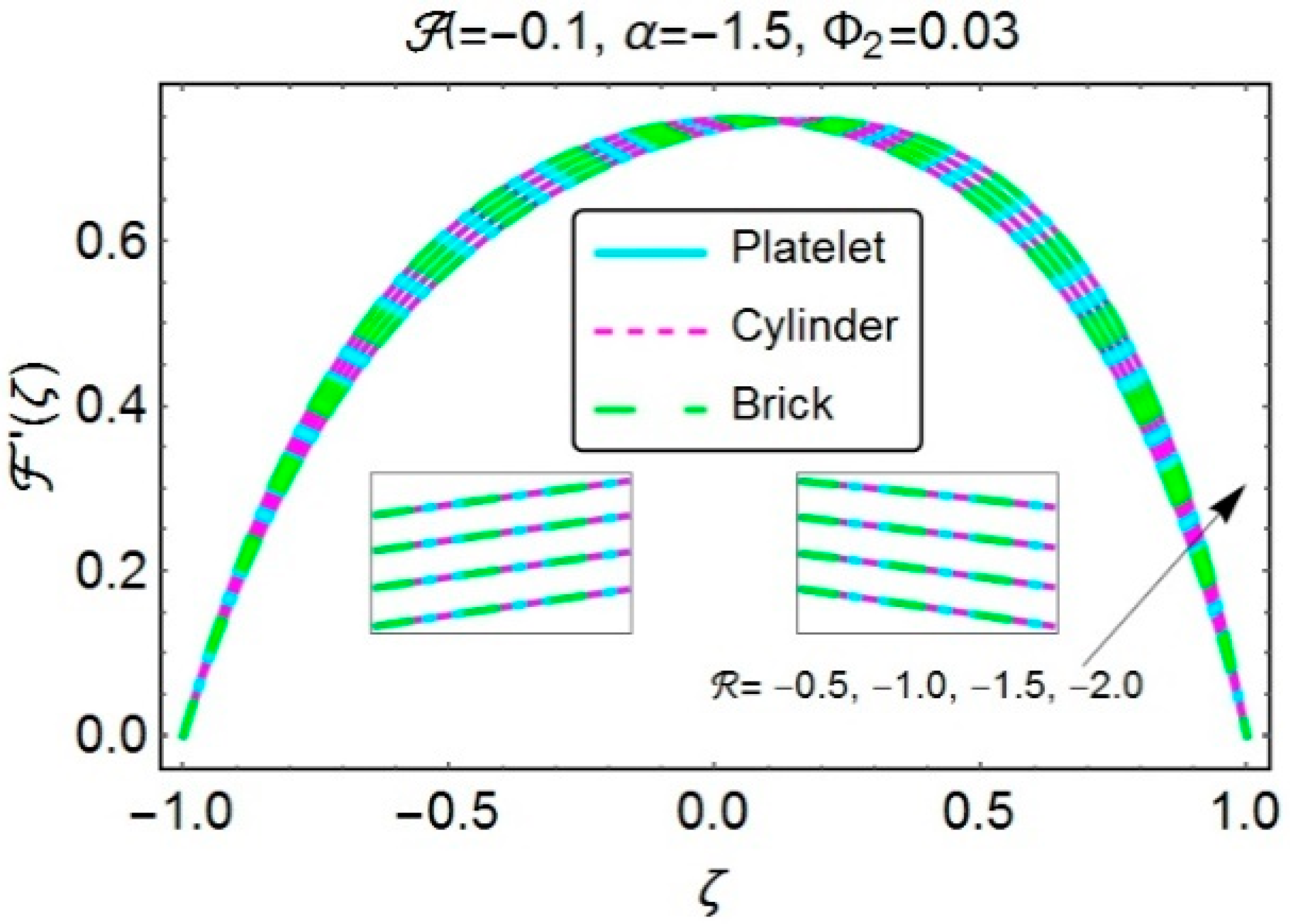
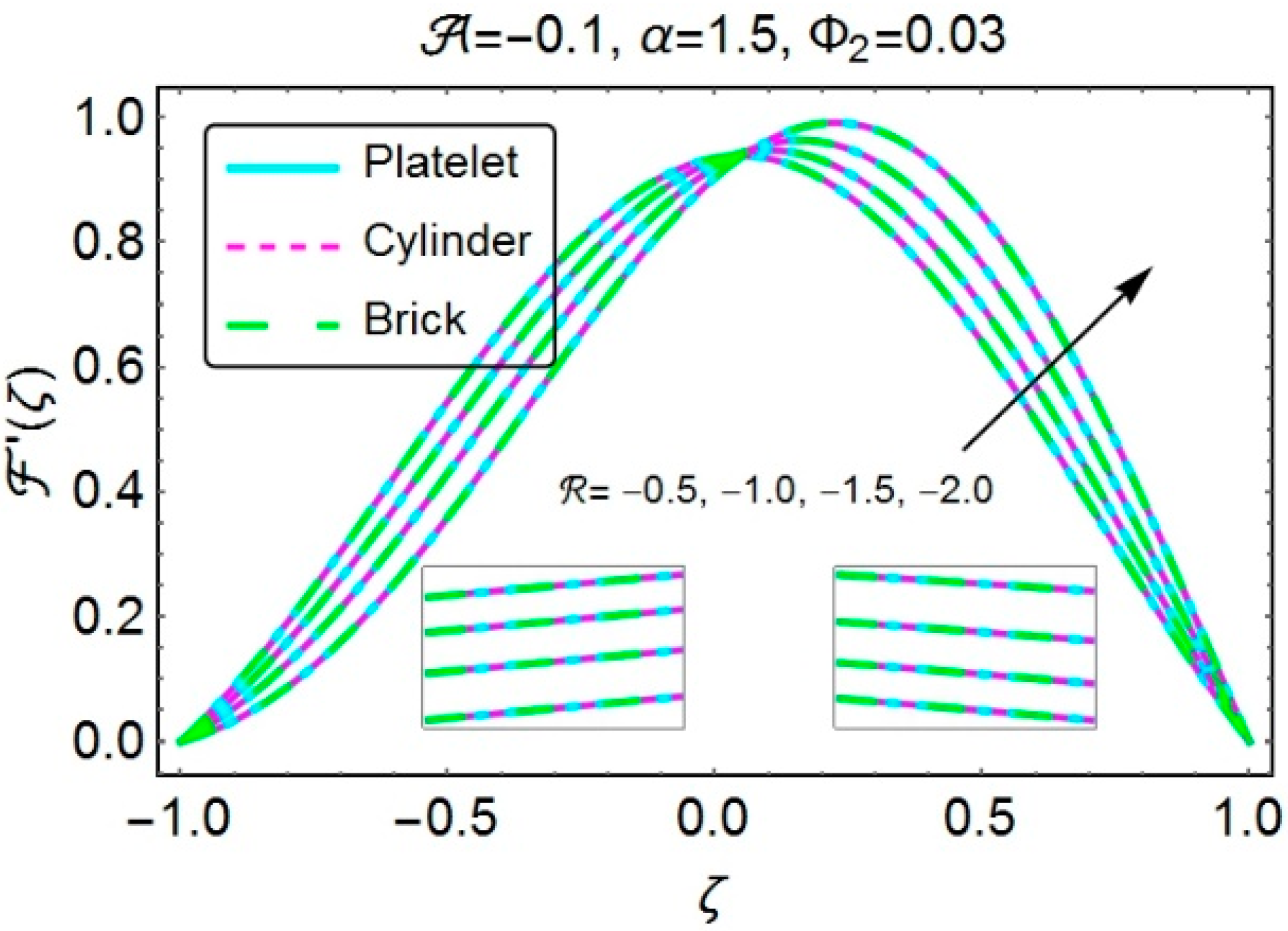
Figure 4 and
Figure 5 expose the consequences of velocity profile against the increasing
, i.e., the case of dilating channel coupled with suction and injection. It was observed form both the figures that depending onwhether the fluid has been injected or sucked through the walls, the channel’s dilation creates a vacant space nearby the walls which is then filled by the inward motion of the adjacent fluid layers. Therefore, the flow has been decelerated in both the cases (injection/suction) which in turn causing a decline in the velocity near the wall. Thus, to preserve the momentum, the velocity of the fluid speeds up in the central half of the channel for increasing values of
. Again, velocity profile seems to be least affected by the nanoparticles shape.
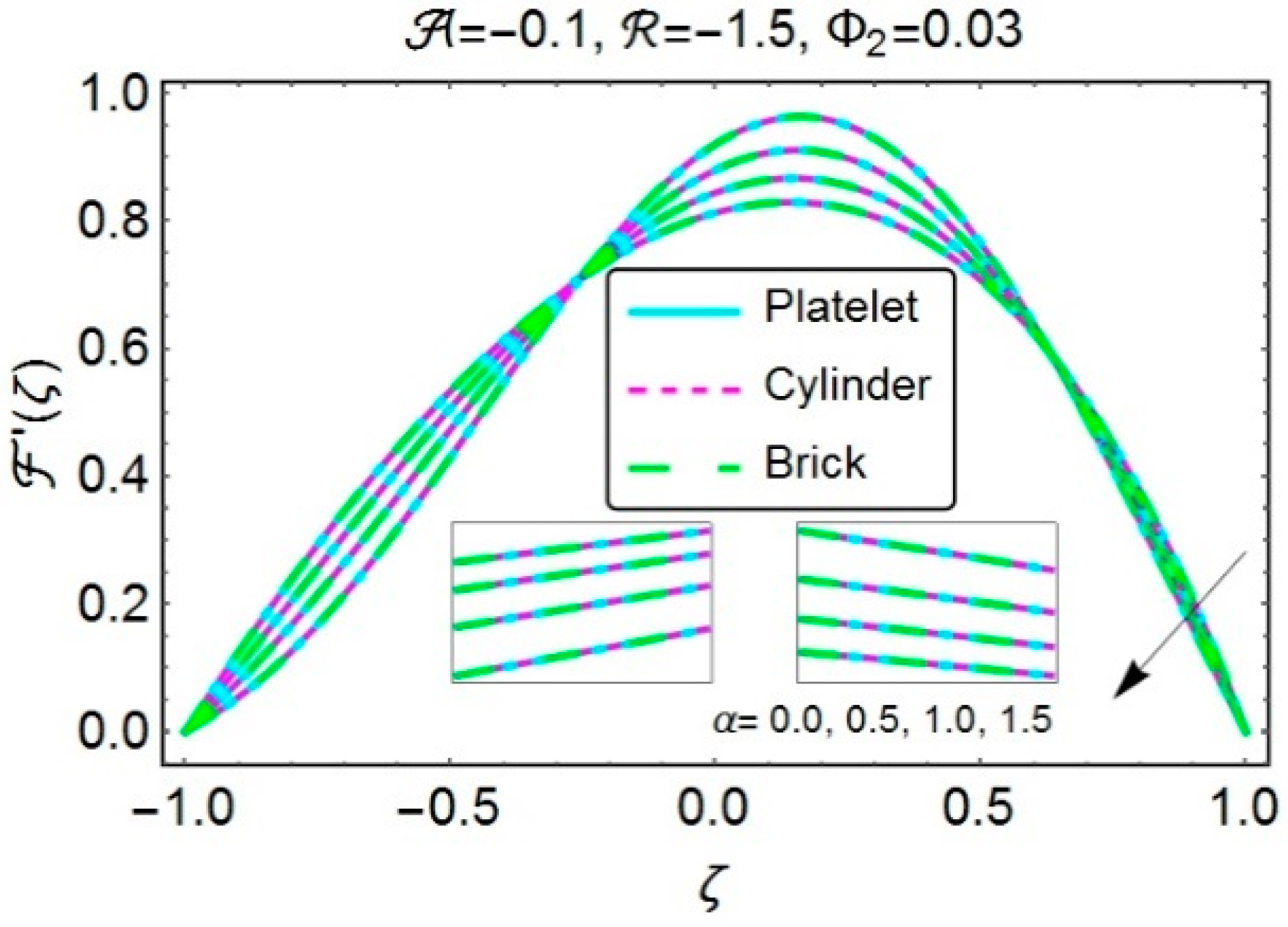
To check the flow behavior, when the suction or injection takes place at the walls along with embracing or parting motion,
Figure 6,
Figure 7,
Figure 8 and
Figure 9 are plotted. The graphs are sketched for the growing absolute values of the permeation Reynolds number
.
Figure 6 elucidates the case when the walls simultaneously experience the squeezing motion and suction. The absolute rise of
produces a decline in velocity which has been detected in the region below the central line of the channel. The permeability parameter
might be a reason behind this behaviour. Thus, the value
implies that the suction dominates in the region above the central line of the channel and as a result a speedy flow has been perceived in this region.
Figure 7 has been decorated for the case when the dilation along with suction takes place at the same time. An almost similar velocity behaviour has been detected with a clear deviation. From
Figure 8 and
Figure 9, one can clearly notice a reverse behaviour in the velocity as compared to
Figure 6 and
Figure 7, when the phenomena of injection simultaneously combined with dilation and contraction. In all the above-mentioned cases, the velocity profiles remain unchanged for different shapes of Cu nanocomposites.
Our next goal is to investigate the temperature behaviors under the influence of various involved parameters. Over here, we only consider the cases when the injection combined with embracing or parting motion, just to maintain the length of the article. Since, Al
2O
3 has been considered as a nanofluid in which Cu nanocomposites have been latterly dispersed, therefore, the proportion of Al
2O
3 nanoparticles within the base fluid (water) remains fixed (i.e.,
).
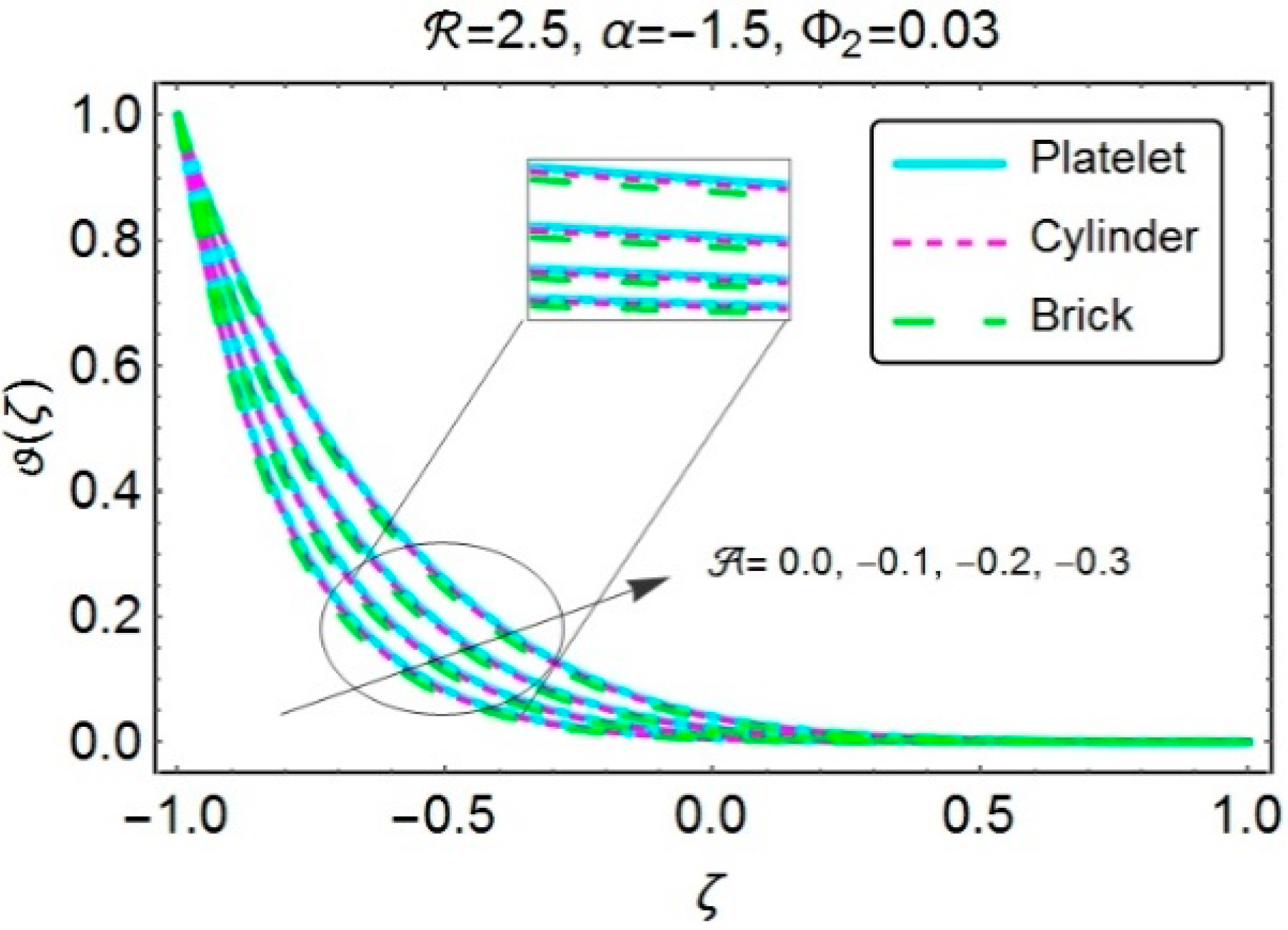
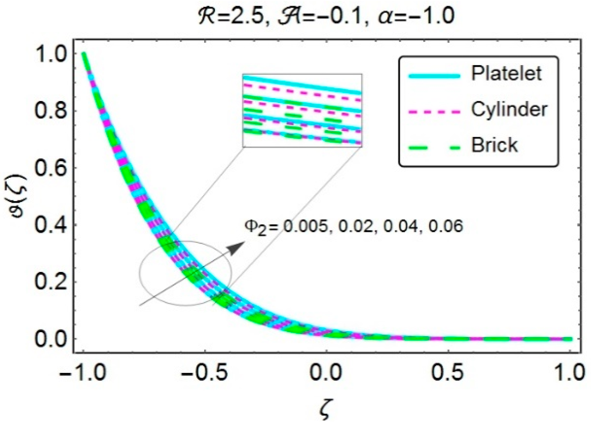
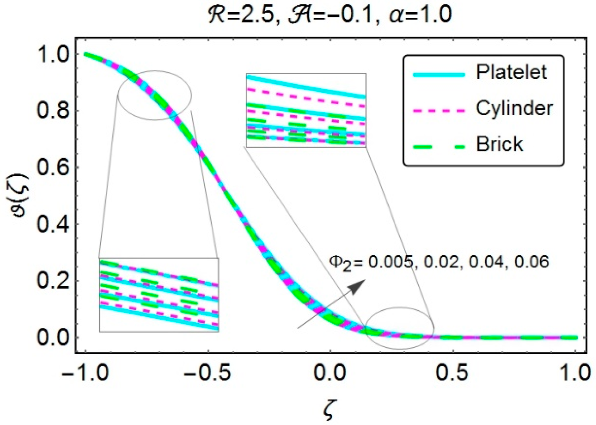
Figure 10 and
Figure 11 helps to visualize the impact of permeability parameter
simultaneously coupled with the cases of injection/dilation and injection/squeezing on the temperature profile. An increment in temperature has been recorded with the increasing absolute
. Since the temperature of the wall at the top is less than the bottom one, therefore a minimum temperature was observed in the region close to the upper wall. The fluid injected from the lower side of the channel bears a high thermal energy, therefore it significantly raises the temperature of the fluid in the region close to the bottom wall. As the fluid moves onward, it gradually experiencing a loss in energy and hence leaves the region adjacent to the upper wall with the minimum temperature. This phenomenon is more prominently observed in
Figure 11, when injection is accompanied by dilation. In first case, platelet shaped nanocomposites possess higher temperature values, while, in the second case, the platelet shaped nanostructures prominently found in the region away from the bottom wall.
Figure 12 has been painted with the nanoparticle volume fraction
as a varying parameter to discuss the similar case as in
Figure 10. A definite rise in temperature has been recorded in the lower half of the channel. The temperature’s pattern seems to be dominant for the platelet shaped nanoparticles as compared to the cylindrical or brick shaped nanoparticles.
Figure 13 deals with the case when the injection has been considered along with dilation. The readers can clearly observe a drop in the temperature in the earlier (lower) half of the channel while a rise has been perceived in the upper half of the channel. Moreover, the platelet shaped nanocomposites shows its dominancy in the upper region of the channel.
To check the impacts of various embedded parameters on the local Nusselt number,
Figure 14,
Figure 15,
Figure 16,
Figure 17,
Figure 18 and
Figure 19 are plotted. The horizontal axis has been decorated with the numerous values of
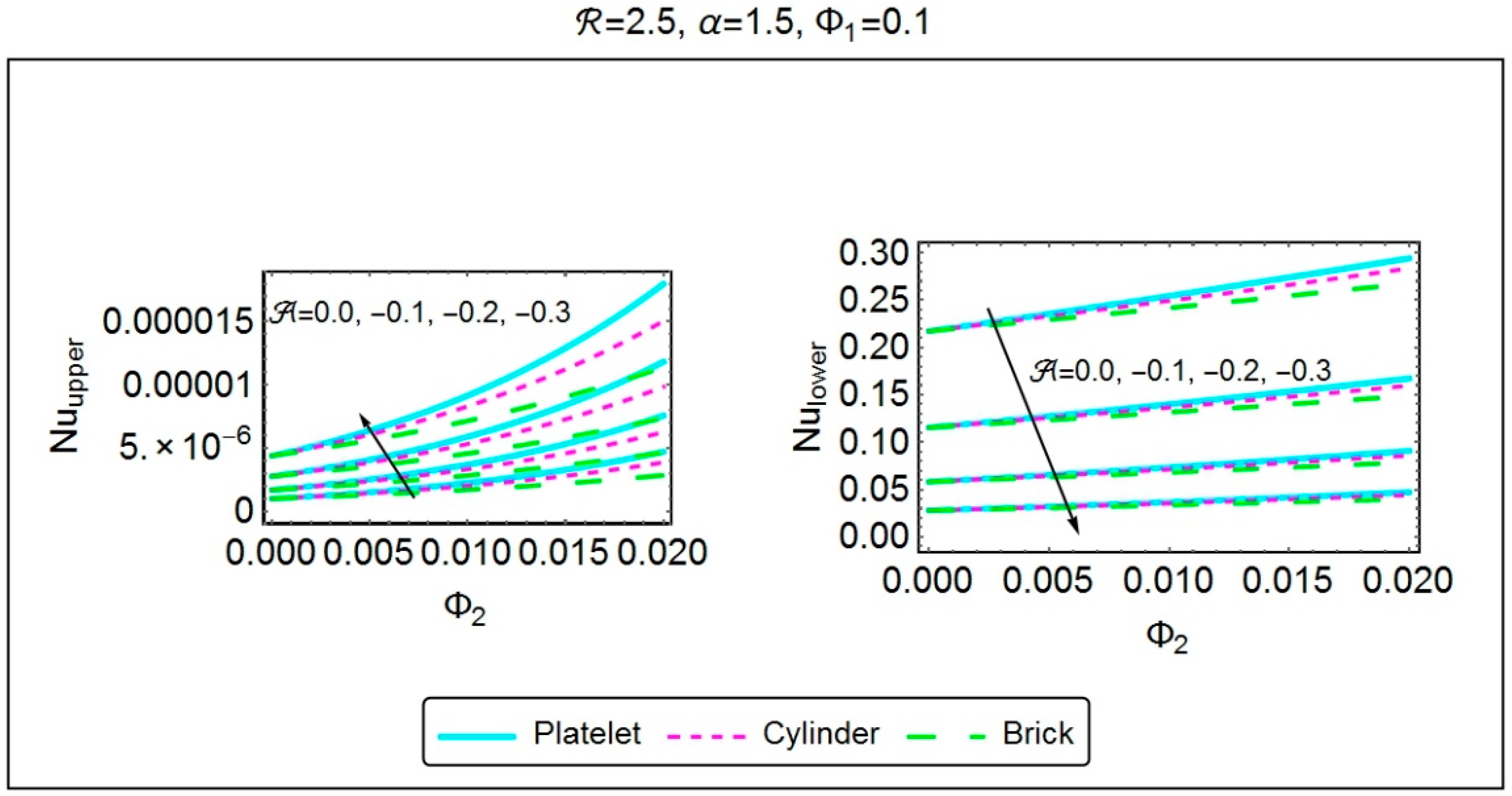
. From
Figure 14, the case when injection combines with contraction, the growing values of
increases the Nusselt number at the top wall. It also provides a similar increment for rising absolute
. Besides, the lower wall exhibits a drop in Nusselt number with the augmented absolute
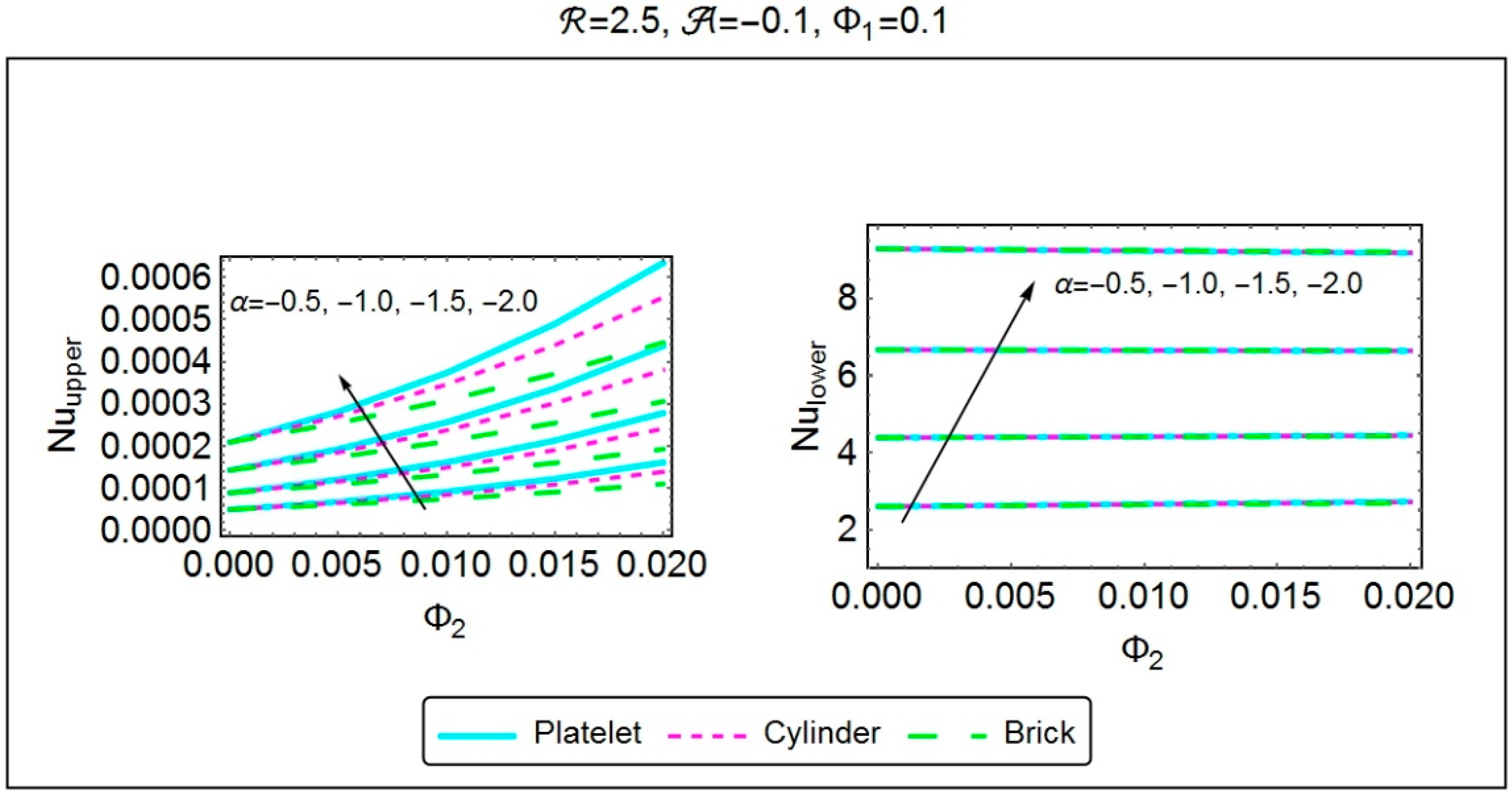
. Clearly, the rate with which heat transfer occurs at the top wall reveals augmented values for the platelet shaped nanoparticles. The case where injection accompanied by dilation,
Figure 15 exposed the deviations in Nu with the growing absolute
both at the top and bottom walls. Again, it has been noticed that the platelet shaped nanocomposites have higher ability of transferring the heat as compared to cylinder or brick shaped tiny particles.
With the growing
, one can clearly observe a decrement in the local heat transfer rate and it has been displayed in
Figure 16 (suction/squeezing). However, an augmentation in the Nusselt number has been perceived with the growing volume fraction. Moreover, continuously squeezing the walls transmit a high amount of heat from both the walls. Also, platelet shaped tiny particles experiences a high amount of heat transfer as compared to others at the bottom wall, whereas, a reversed behavior has been seen at the top wall. In the subsequent case of injection/squeezing,
Figure 17 has been plotted for the varying values of
which displays the similar preceding results of
Figure 16, i.e.,
enhances at the both walls. Furthermore, the platelet shaped nanostructures possess high transmission of heat at the upper wall of the channel.
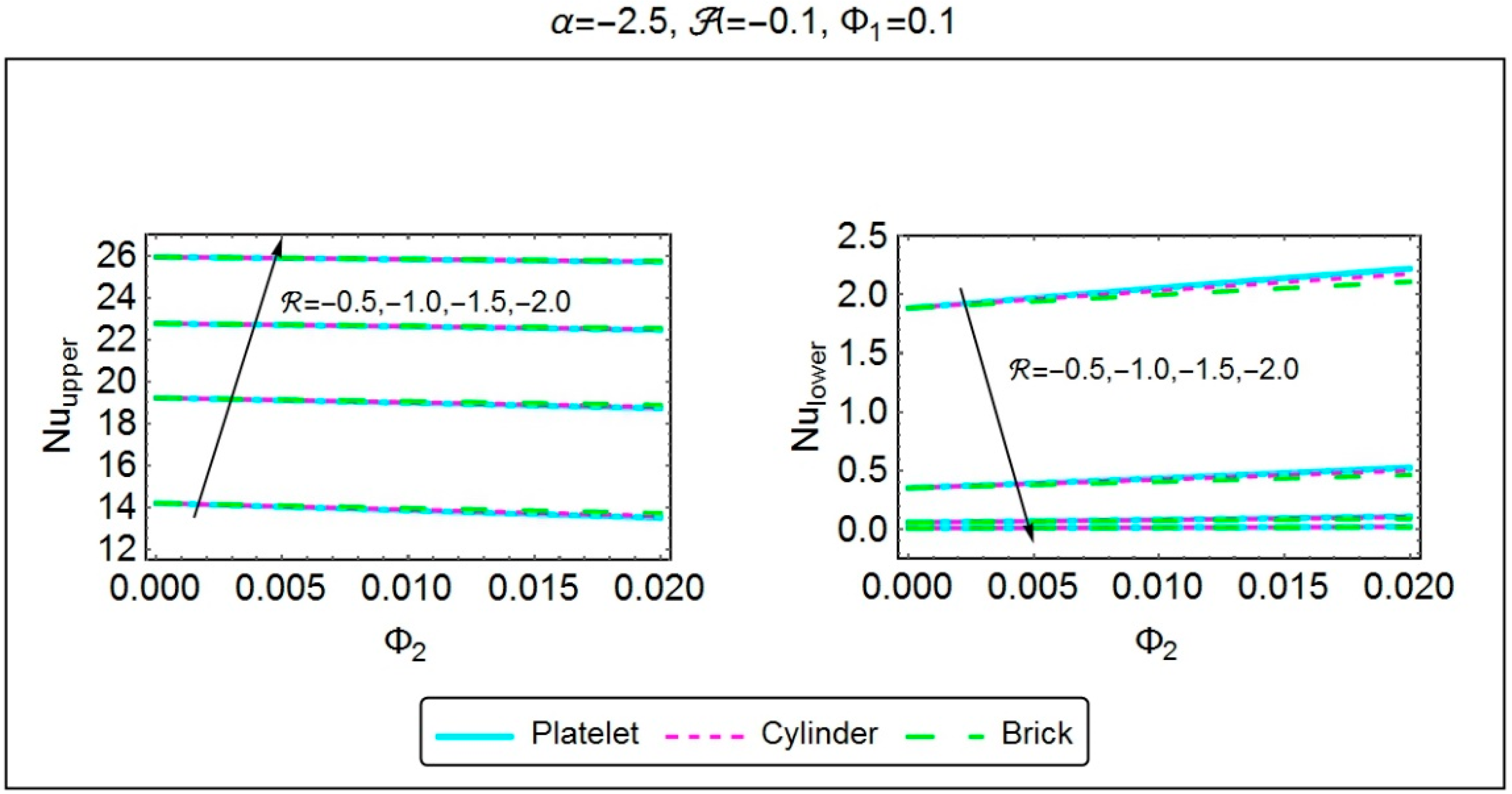
For the case of squeezing/suction,
Figure 18 has been sketched to see the consequences of rising
along with absolute
on the Nusselt number. One can notice a clear decline in Nu
u with increasing
, while an enhancement has been perceived with rising absolute
. Moreover, a reversed behavior was observed for Nu
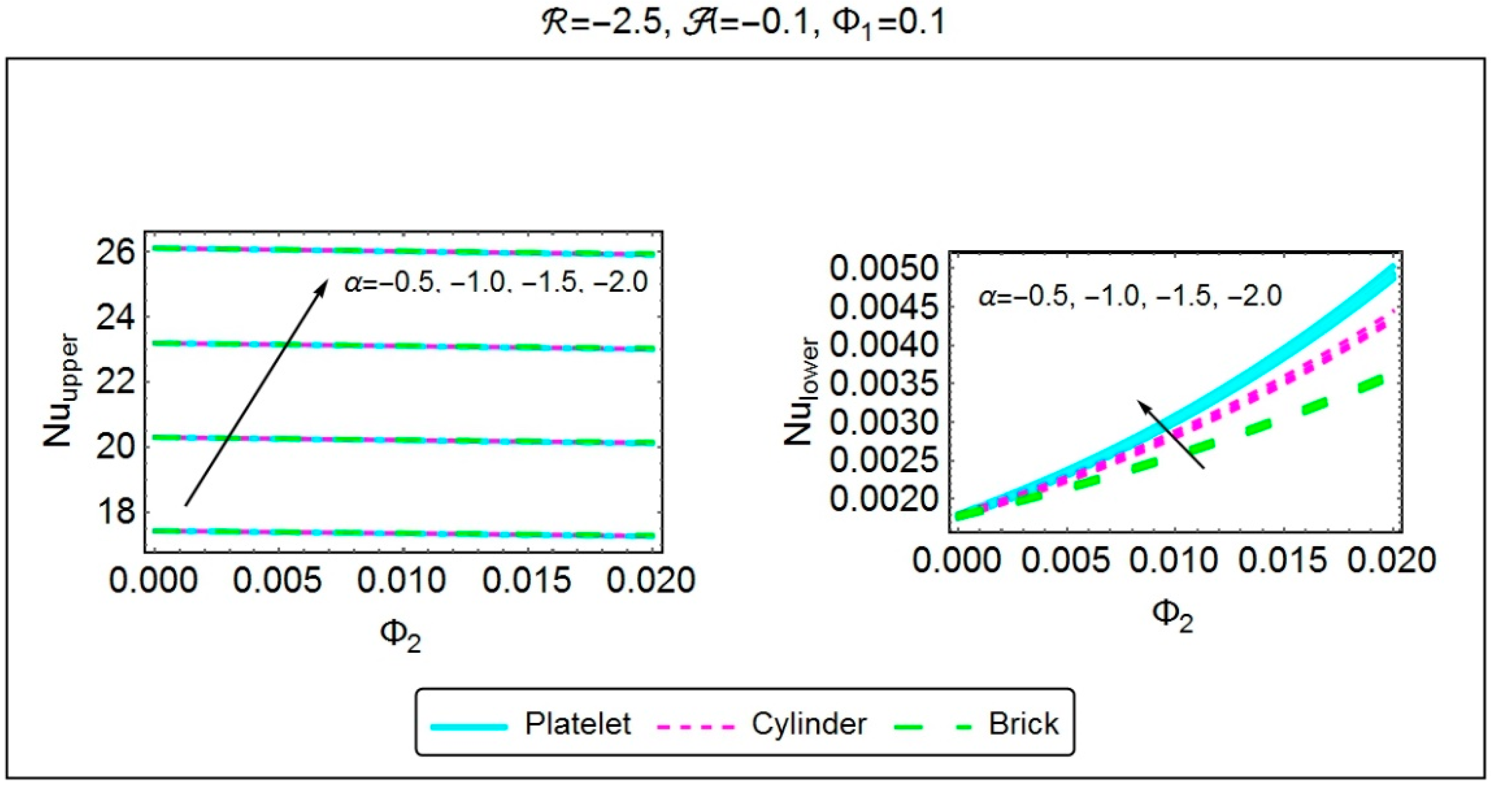
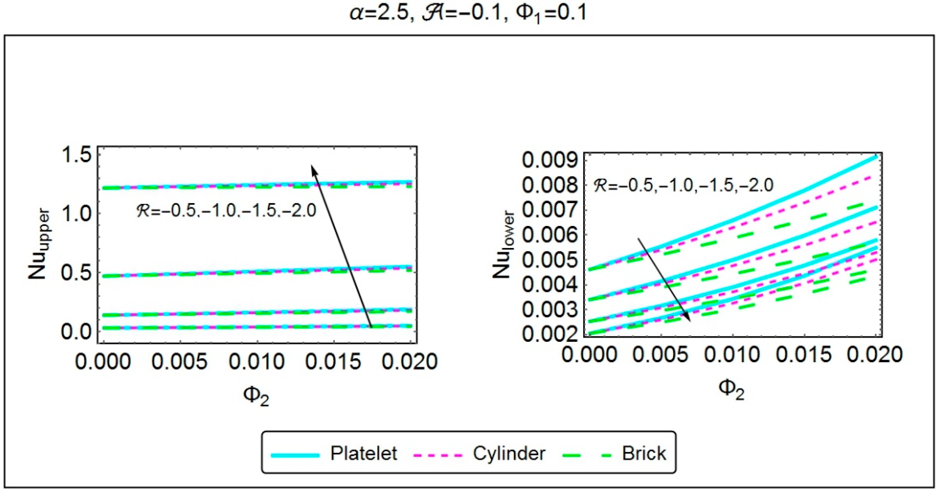
l from the adjacent figure. Also, platelet shaped tiny particles shows a higher heat transfer rate at the bottom wall of the channel. For the case of dilation/suction,
Figure 19 has been plotted to highlight the significances of rising
and
upon the Nusselt number. The rising values of
depict an increment in the behavior of Nu at the both walls. Likewise, the growing absolute
simultaneously enhances the heat transmission rate at the top wall and it decreases at the bottom wall. Further, it is noteworthy that platelet shaped nanocomposites prove their ability of transferring the heat at the high extents and it can be observed at the both wall.

 ,
, 


