1. Introduction
Due to fossil fuel depletion and environmental pollution around the world, the development of renewable energy, such as wind and photovoltaic, has attracted much attention [
1,
2,
3,
4]. The distributed generation (DG) systems based on renewable energy can be connected in parallel with each other to form a micro-grid. The analysis of field data of photovoltaic (PV) plants indicates that the harmonics at point of common coupling (PCC) in weak grid can exist stably for a long time and the line impedances of low-voltage power distribution systems cannot be ignored [
5]. Harmonics in micro-grid may cause abnormality of distribution system and even damage of power facilities, further reducing power quality and even causing the shutdown of PV inverters [
6]. In [
7,
8], the PV inverters operated in parallel can shift the resonant frequency to a low frequency band, and these resonances of inverters can take place at the frequencies of 5th and 7th harmonics. With the high penetration of nonlinear power electronics devices, the impact harmonic resonance between inverters and grid is more complicated. Traditionally, many studies are only implemented for a single power electronic equipment and single renewable energy penetration level, neglecting the interaction between new devices and micro-grids, as well as revealing little generation mechanisms about the PCC harmonic of renewable energy. In [
9,
10], the generation mechanisms of multi-inverter resonances are studied by establishing inverter parallel models, and a virtual impedance method was proposed to suppress these resonances. On the other hand, the serial resonant frequencies between PV inverters and line impedances can also shift to the lower band because of the high line impedance in weak grid. The output harmonics of grid-tied PV inverters are generally concentrated in low-frequency bands, and it is probable to cause resonances at PCC [
11]. In [
12,
13,
14], the impedance matching analysis method of serial resonances between power converter groups and grid impedances is proposed, and a harmonic linearization model is studied. In [
15,
16,
17,
18], the companion harmonic circuit modeling is adopted to develop an electronic device and micro-grid combine model, which can analyze the adverse effects of harmonic distortion in weak grids. It also produces a very easy solution method.
For renewable energy generations, almost all dispatched loads and parallel reactive power compensating devices work in a frequently changing way [
19]. The parameters of equivalent admittance/impedance of fundamental and harmonics of these equipment exist in uncertainty, which will significantly change the harmonic network admittance matrix of micro-grid [
20]. Due to the rapid increase of photovoltaic systems in micro-grids, the problem of power quality associated with the intermittent nature of these systems had become more and more serious, and many efforts have been made already [
21,
22]. Most of the strategies about harmonic suppression in micro-grid focus on the power grid models containing one PV inverter, hence it is necessary to establish a model associated with a multi-inverter-based micro-grid [
23,
24]. In [
25,
26,
27,
28,
29], a composite method to study the impact of harmonic sources on the distribution system is proposed. This approach combines a bottom-up stochastic modeling of the local loads with harmonic waveform data and power-flows all based on a scenario analysis. Based on the analysis of the measurement data, a prediction of the harmonic current level in a residential area can be performed by the method on the current situation. The purpose of this research is to study the harmonic generation mechanism and suppression method by establishing a combined model of micro-grid. In [
30,
31], it is mentioned that the phase-locked loop (PLL) is the most important grid synchronization technique in grid-connected power converter applications. However, its phase-tracking performance is affected seriously by the unbalances and distortions of micro-grid voltage. It is important for a grid-tied inverter, even when the grid is subject to harmonics, to maintain the harmonic contents of inverter output currents below the specified limit. Therefore, some research is focused on the inverter PLL performance to analyze the PV PCC harmonic generation mechanism in a micro-grid [
32,
33].
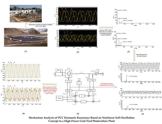
The studies above reveal a fact that the analysis of harmonic generation mechanisms are the key issues of harmonic mitigation for the power systems containing distributed generations, such as photovoltaics and wind generations. All the methodologies above of micro-grid harmonic research include theoretical analysis, modeling, simulation and experimental research. The study results obtained by these methodologies are not completely consistent with the actual results in field, such as PV PCC harmonics in micro-grid. Therefore, it is necessary to study the power quality problems in PV plants based on effective field testing and data measurement. In this paper, a field test and analysis method of a PV plant harmonics is presented, and a new generation mechanism of PV PCC harmonics is proposed.
2. Analysis of PV PCC Harmonics
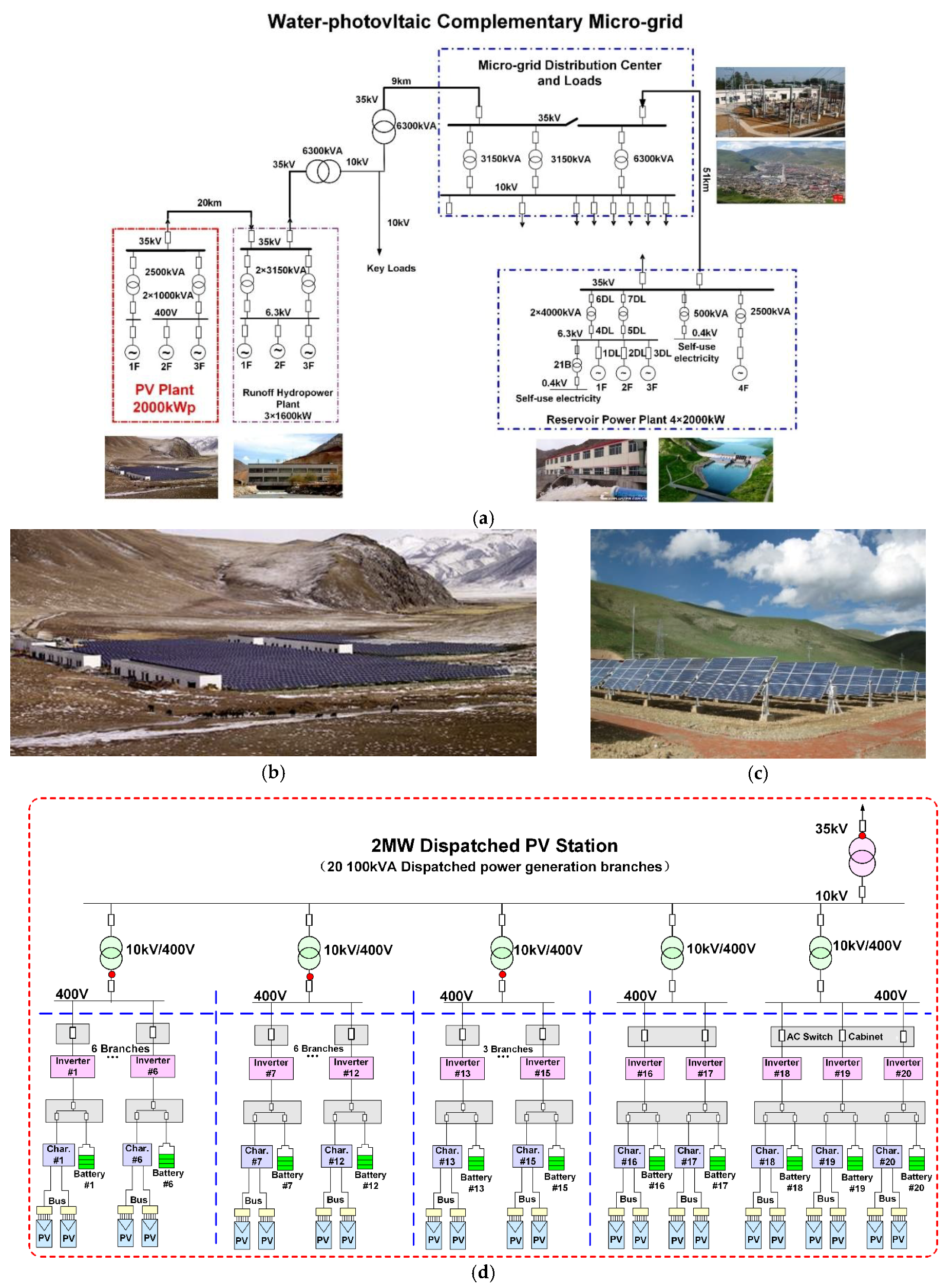
To analyze the PCC harmonics of high-power PV plant with multiple grid-tied inverters, a micro-grid containing photovoltaic and hydroelectricity was addressed. This micro-grid is located in Batang Town, Yushu Prefecture, Qinghai Province, in western China, and the distance from large grid to the micro-grid is more than 400 km. The capacity of hydroelectricity as the main power source of the micro-grid is 12.8 MW. The load peak of this micro-grid is 12 MW. Under the influence of the flood season and the dry season, hydroelectricity cannot meet the needs of power in winter. The power supply gap is large, especially during the peak hours in the evening. Therefore, the construction of a PV/energy-storage generation system was implemented to improve the power supply of the micro-grid. However, significant harmonics appear frequently at PCC of the PV plant when PV inverters are working. The micro-grid and PV plant are depicted in
Figure 1.
As illustrated in
Figure 1, the capacity of the PV plant was 2 MWp, and the rated power of each inverter was 100 kW. The topology of these inverters was a standard current-source converter (CSC) and the output filter consisted of an inductor and a capacitor. The capacitance and conductance of inverter filter were 47 × 10
−6 F and 0.25 mH, respectively. Each grid-tied transformer was connected by 3–6 PV inverters in parallel, and the transformers are connected to PV PCC of the microgrid. The ratio of these grid-tied transformers was 10 kV/400 V, and the ratio of isolating transformer in PV inverters was 400 V/215 V. The proportional integral (PI) regulators in
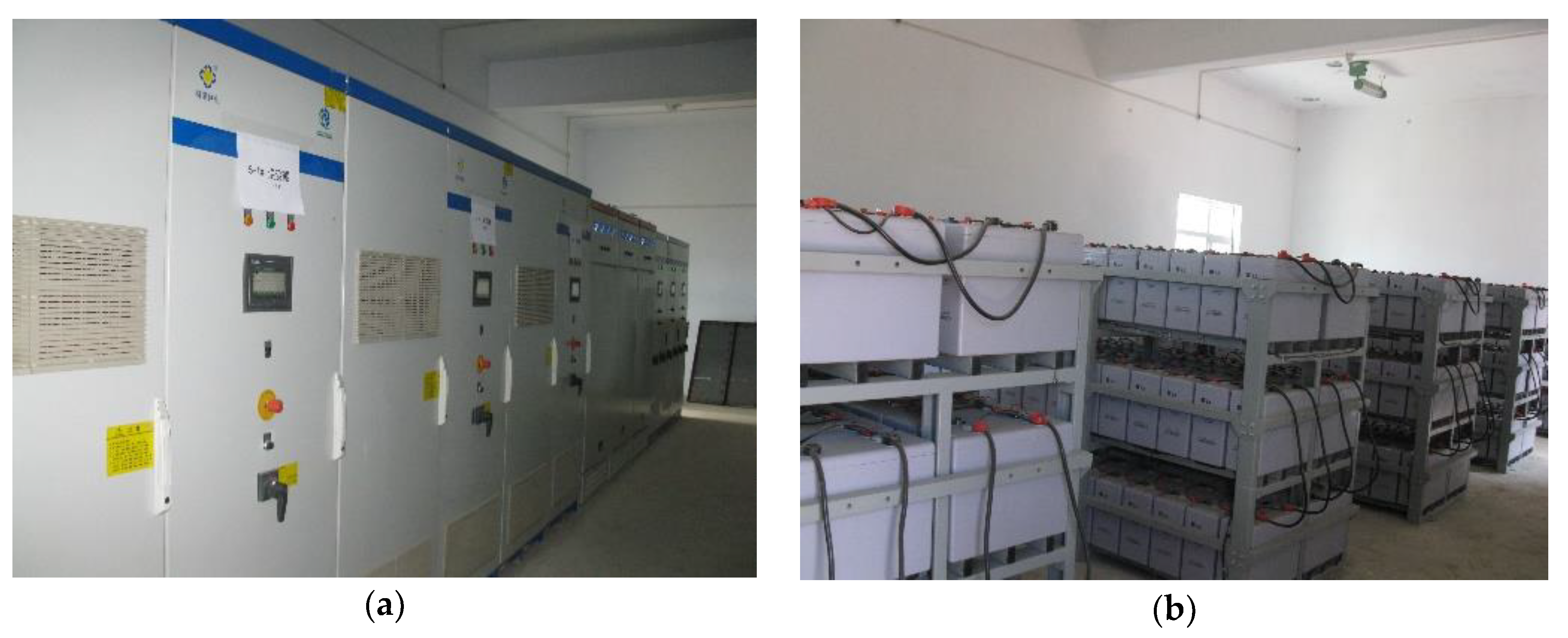
dq reference frame were adopted by PV inverter controllers. The capacity of energy storage system was 15.60 MWh. As a result, the PV inverters were working with an ideal direct current (DC) supply and the harmonic analysis could focus on the PCC of PV plant. The grid-tied inverters and energy storage of PV plant are presented as
Figure 2.
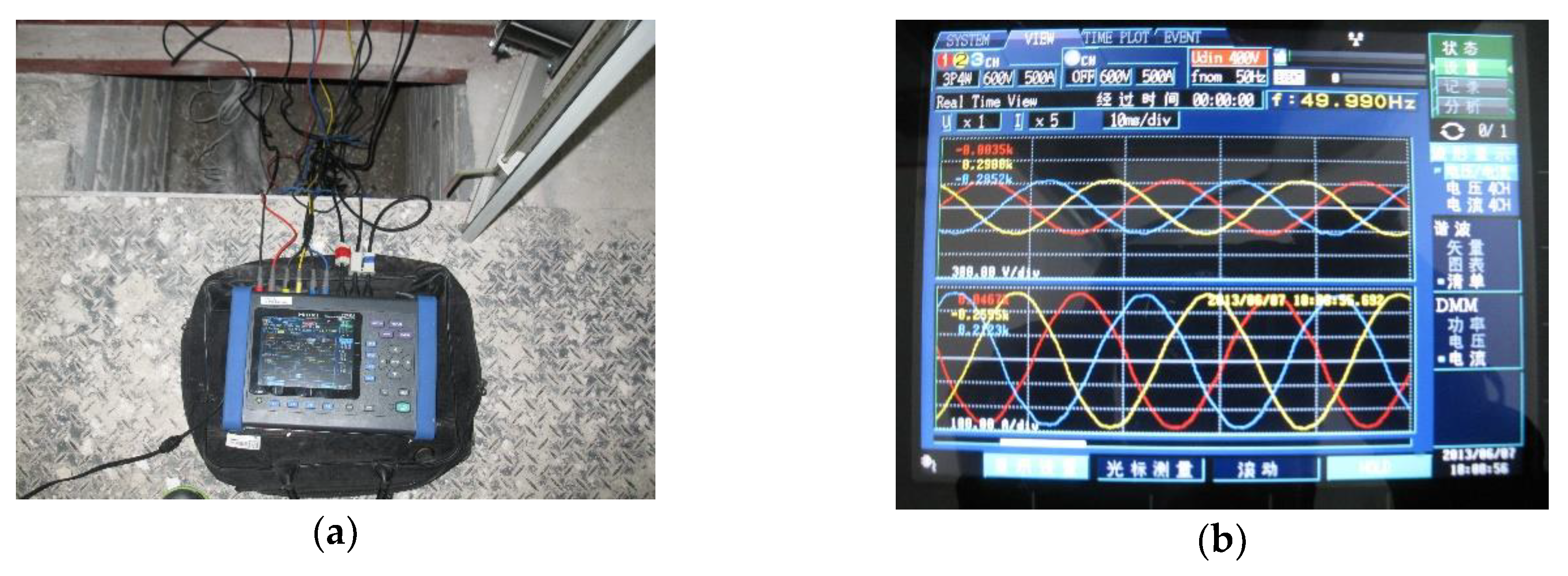
PV inverters with different generation power were operated. The voltage and current waveforms of PCC with low output power of PV inverters are depicted as
Figure 3.
As illustrated in
Figure 3, the PCC waveforms were perfect. The harmonic waveforms, when the output power of PV plant was about 65% of rated value, are presented in
Figure 4.
As illustrated in
Figure 4, the waveforms of PCC voltage and current were recorded by data acquisition instrument YOKOGAWA DL850 ScopeCorder (Yokogawa Test & Measurement Corporation, Musashino-shi, Tokyo 180-8750, Japan) and the sample frequency was 20 kHz. The main harmonic components were steady-state, and the harmonics were significant (total harmonic voltage distortion (THDU) of 15% and total harmonic current distortion (THDI) of 40%). Total power factor was 0.95 and the power factor of fundamental signals was 0.99. However, the voltage and current waveforms in
Figure 4 were not symmetrical perfectly, and this phenomenon revealed the existence of inter-harmonics at PV PCC. There are spectral leakage and fence effects when any inter-harmonics are analyzed using discrete Fourier transform (DFT) or fast Fourier transform (FFT) algorithms. Therefore, the waveform measurement data in the PV plant of the micro-grid were analyzed using windowed interpolation Fourier transform (IpFFT) method.
IpFFT is an improved FFT algorithm with high frequency resolution and accurate analysis of signal phases and amplitudes [
34,
35]. The effects of spectral leakage and fence of DFT algorithm can be mitigated by IpFFT methods. Windowed interpolation Fourier transform algorithm based on Hamming window was employed in this study. The Hamming data window is as follows:
The window is adopted to the signal data in time domain. DFT or FFT algorithm is employed to the windowed signals to obtain the signal spectra. More accurate amplitudes, frequencies and phases of signal spectra can be calculated by the IpFFT interpolation formula. The interpolation formula of Hamming IpFFT algorithm in frequency domain is presented as:
where
X(
l) and
X(
l + 1) are the highest and second highest spectral lines of one spectral peak of windowed signal spectrum, respectively;
is the interpolation factor;
is the frequency deviation; and
Al,
fl and
are the estimations of the amplitude, frequency and phase of a harmonic, and their units are V, Hz and (°), respectively.
The harmonic analysis results of phase A voltage and current of PV PCC signals by IpFFT algorithm are shown in
Figure 5.
As illustrated in
Figure 5c,d, the spectra of PCC voltage and current waveforms recorded by DL850 ScopeCorder did not contain any significant background harmonics although the PV inverters were still working. When the production in the PV plant increased, as shown in
Figure 5a,b, PCC harmonics occurred; the frequencies of the two significant harmonic components are 202.90 Hz and 302.90 Hz. These components are inter-harmonics with frequencies near 4th and 6th harmonic frequencies. The frequencies of the two inter-harmonics are denoted as
f4 and
f6, respectively, and the fundamental frequency is denoted as
f1. The difference (denoted as
f6-
f4-2
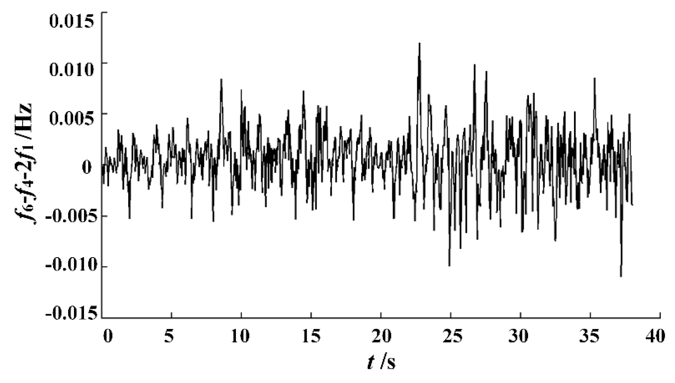
f1) of these harmonic frequencies and double fundamental frequencies during 40 s is presented in
Figure 6.
The curve illustrated in
Figure 6 reveals that the algebraic difference of the three frequencies is within the range of (−0.01 Hz, 0.01 Hz), and evenly distributed. It is considered that the frequency difference between the two inter-harmonics is twice the fundamental frequency (2
f1). The same frequency difference relationship exists between the two inter-harmonic components in the B-phase and C-phase signals. Such frequency difference relationship was satisfied as long as the PV PCC harmonics occurred. The waveforms recorded at other times led to the same results of the PCC harmonics in the PV plant. In addition, there is a special relationship between the phase sequences of PCC harmonics.
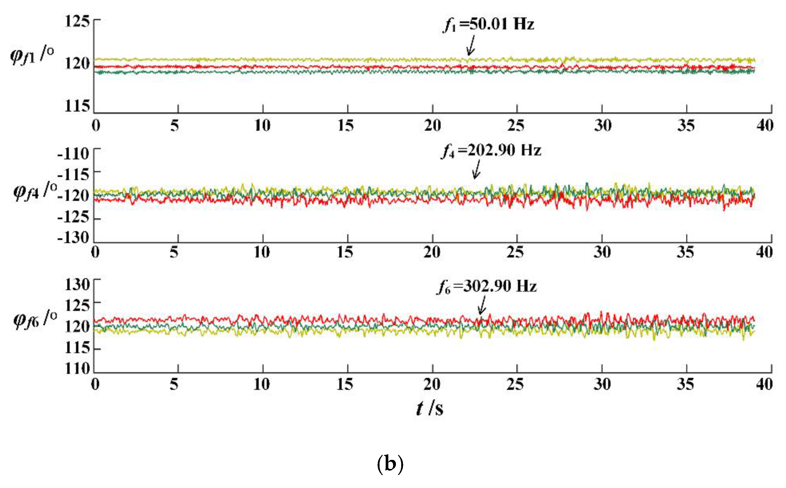
The phase sequences of the fundamental and inter-harmonics were calculated for 40 s, as presented in
Figure 7.
The phase sequences of the fundamental and two inter-harmonics are denoted as
,
and
, where the yellow curves are phase A vs. phase B, the green curves are phase B vs. phase C, and the red curves are phase C vs. phase A. The curves illustrated in
Figure 7 indicate that the phase sequences of the inter-harmonics (
and
) are symmetric, such as the same phase difference and opposite phase sequence. Further analysis shows that the amplitudes of the two inter-harmonic voltages are very close, and all the voltage root mean square (RMS) are about 24.00 V. The correlation of frequency, phase sequence and amplitude show that the inter-harmonics at PCC are not independent from each other and come from the same source. Therefore, it is inspiring to analyze the harmonics in the output circuits of PV grid-tied inverters.
3. Harmonics of Inverter Outputs
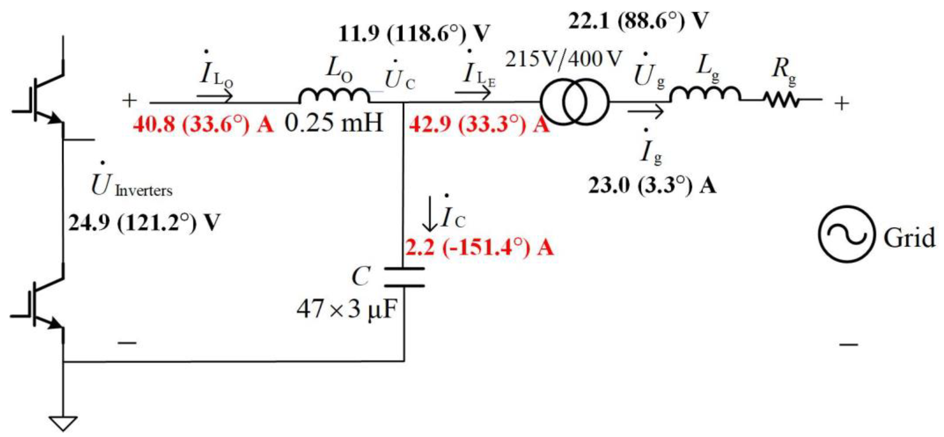
Single-phase output equivalent circuit of grid-tied inverters can be performed as
Figure 8 when the three-phase output filter is symmetrical. The parameters of output circuits of PV inverters can be found in
Table 1.
LO and
C are filtering inductor and capacitor, respectively;
Lg and
Rg are line impedances of the micro-grid, and the ratio of isolating transformer in the PV inverters is 400/215. When the line resistor
Rg can be ignored, the output impedance of PV inverter can be depicted as
where
LE is the equivalent inductance of the isolating transformer in the PV inverters. The
LCL resonance frequencies of output equivalent impedance
Z are related to inductors
LO and
LE and capacitor
C.
Based on Kirchhoff’s current law and the reference directions of branch currents of PV inverter output filter, the current equation below can be satisfied:
where
is the RMS of inverter output inter-harmonic current,
IC is the RMS of capacitor branch current of inverter output filters, and
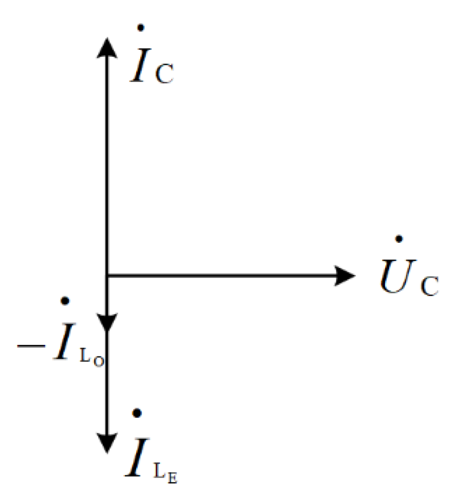
ILE is the RMS of the injected inter-harmonic current into micro-grid. When LCL resonances take place, the RMS of the currents above satisfy the following equation:
The current vectors of LCL resonance are depicted in
Figure 9.
In
Figure 8, considering the 202.90 Hz inter-harmonic, the red data are branch currents and the data in parentheses are the real-time phases of inter-harmonic currents. The inter-harmonic RMS current
IC of 202.90 Hz in capacitor branch was 2.20 A, which was less 1/15 of the RMS of inter-harmonic current
ILO or
ILE with the same frequency.
UInverters was the inverter inter-harmonic voltage at insulated gate bipolar transistor (IGBT)-bridge output of 202.90 Hz, which was the significant one of 202.90 Hz in the PV inverter output circuit. Other frequency inter-harmonics at the PV PCC presented the same characteristics in the inverter output circuits. The analysis results are shown in
Table 2.
All branch harmonic currents and node voltages presented in
Table 2 had the following characteristics: the capacitor inter-harmonic currents (
IC) are very small and much smaller than inductor branch harmonic currents (
and
); and harmonic voltages at inverter bridge (
UInverters) are twice of the harmonic voltages at filter capacitor (
UC).
As illustrated in Equation (5), the LCL resonance of PV inverter filter usually generates a significant inter-harmonic current in capacitor branch, and the voltage RMS of filtering capacitor is the biggest one of all the node inter-harmonic voltages in the inverter output circuits. However, the results of field measurement and data analysis were very different to the LCL resonance: the inter-harmonic voltages and currents in filtering capacitor branches were not significant anymore. The harmonic currents (IC) of the capacitor branches are very small, and the installation of the damping resistors in the capacitor branches did not suppress the harmonics. Therefore, it can be concluded that the inter-harmonics at PV PCC are not generated by LCL resonances of inverter output filters, and the investigations of harmonics at PV PCC in the PV plant should be associated with the inverter control methods, PV plant topology and micro-grid impedances.
When the line impedances are significant (in weak grid), parallel resonances may occur among multiple PV inverters tied in the same PV PCC, and series resonances may occur between the inverter group and line impedances. The latest studies indicate that the parallel or series resonant frequencies are related to the number of inverters operating in parallel: the more inverters there are, the lower frequencies the resonance have [
8,
9,
10,
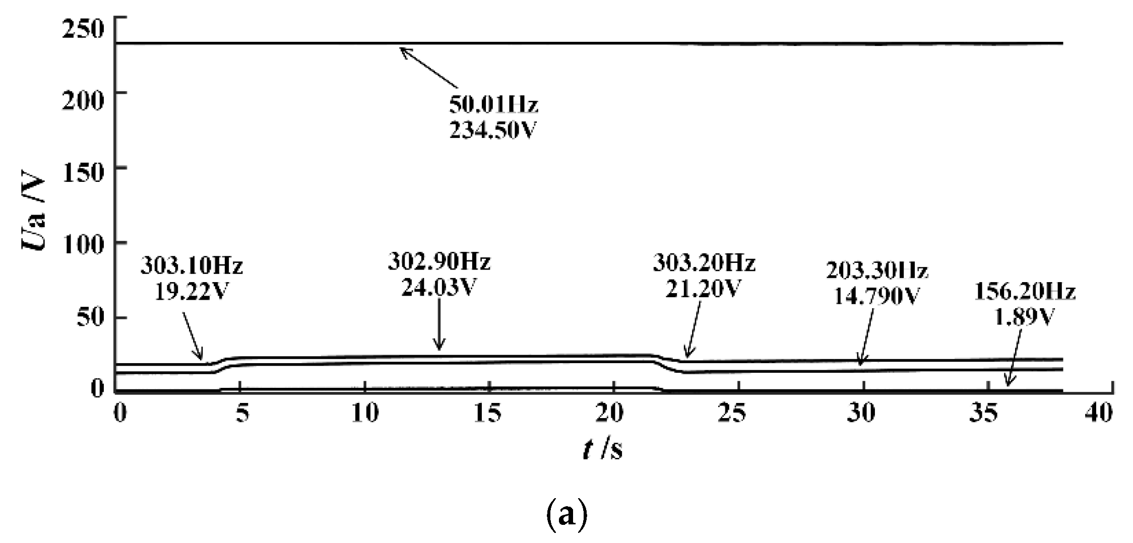
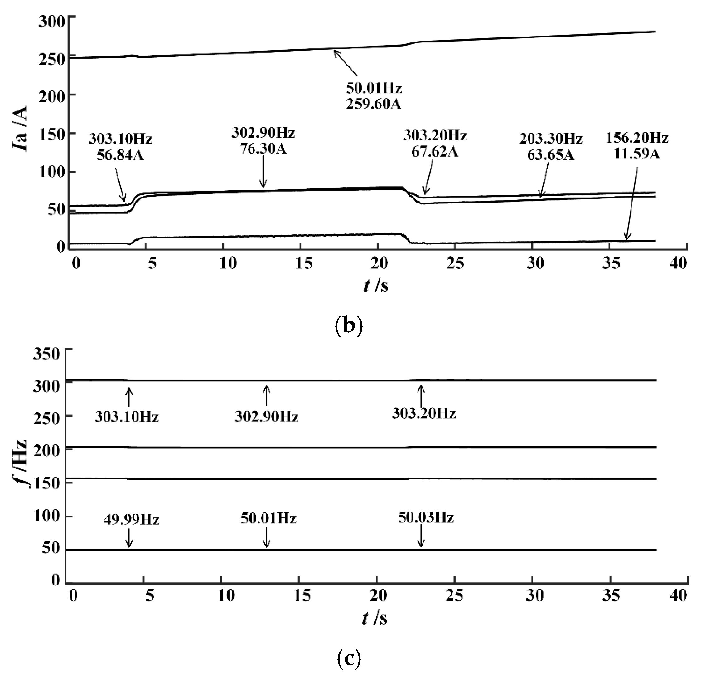
11]. There is a set of measurement data obtained by field test that contained the PCC harmonic waveforms as one PV inverter was online and then offline. Six inverters in the PV plant were connected to one grid-tied transformer in parallel. The waveforms of voltages and currents at PV PCC of changing the number of PV inverters in parallel were specifically studied and the analysis results are presented in
Figure 10.
As illustrated in
Figure 10, the harmonic voltages and currents increased significantly at the time of 5 s, which indicates that one inverter was start-up; all harmonic voltages and currents were stepped down at the time of 22 s, indicating that one inverter was shutdown. During the start-up and shutdown of the inverter, there was almost no change in the inter-harmonic frequencies at PV PCC. In this case, the effect of changing the number of PV inverters in parallel was that the harmonic voltage and current amplitudes changed but the frequencies did not. It can be considered that the harmonic frequencies at PCC in the PV plant were not related with the number of grid-tied inverters, and the harmonics were not generated by the series/parallel resonances of multi-inverters.
4. Harmonic Sources and Simulations
As illustrated in
Figure 5c,d, when the PV inverters were running but no “resonances” existed, the spectra of PV PCC waveforms contained fundamental voltage and current components only.
Figure 5c,d reveals no background harmonics in the micro-grid. To determine the position of harmonic source, the
dq conversion was implemented to the three-phase voltage at PCC and obtained sinusoidal ripples on the
dq axis of the inverter output (DC component removed). The results are depicted in
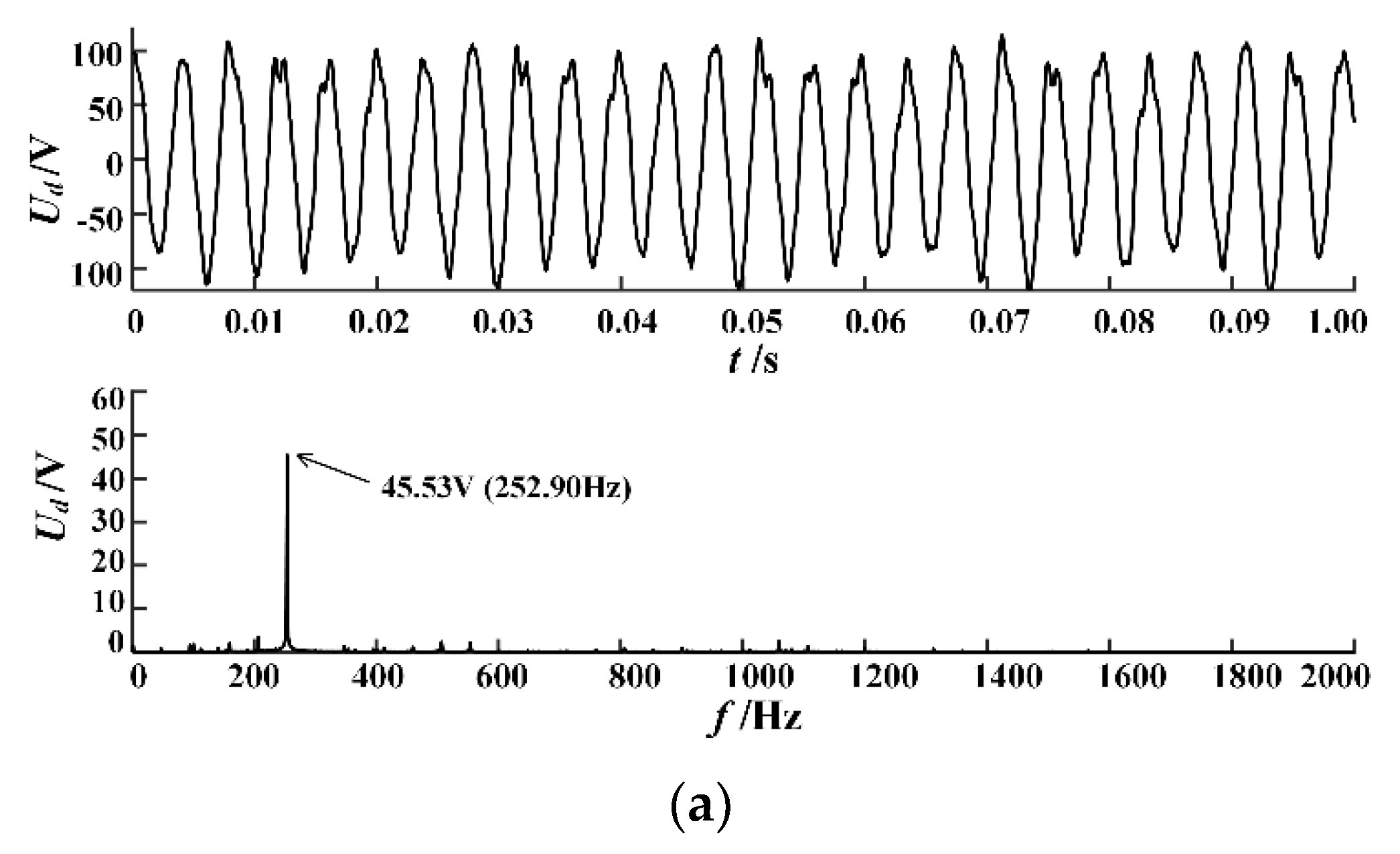
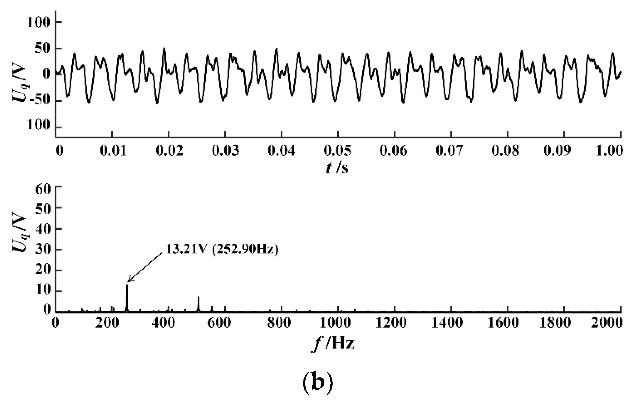
Figure 11.
As illustrated in
Figure 11, there were 252.90 Hz ripples with high amplitudes on
d-axis and
q-axis of PV inverters. The inter-harmonics (202.90 Hz and 302.90 Hz) with significant amplitudes at PCC were generated by this sinusoidal alternating component. This sinusoidal alternating component was generated by nonlinear self-oscillation of PV inverters and micro-grid systems.
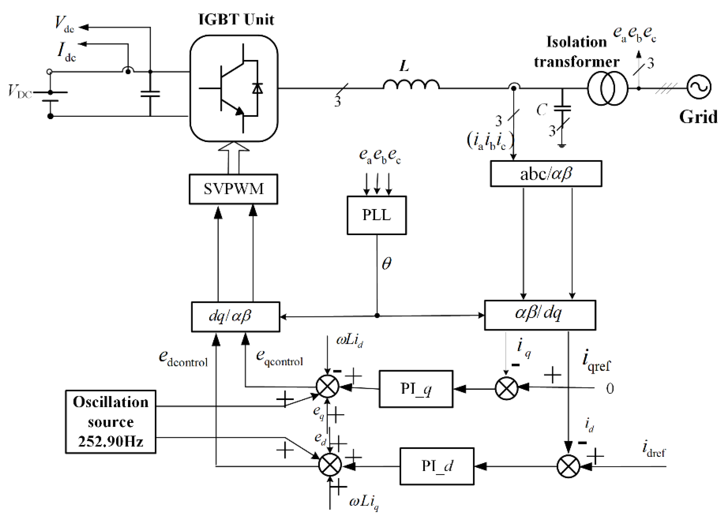
To verify the opinions of nonlinear self-oscillation to generate harmonics at PV PCC, a Simulink (Ver. R2016a, Mathworks, Natick, MA. 01760-2098, USA, 2016) model of “PV inverter and micro-grid” is implemented based on the actual parameters of PV inverters and line impedances of the micro-grid in field, as shown in
Figure 12. The PV inverter works in current source mode; the inputs of PV inverter are connected to an energy storage system with constant DC voltage as the PV plant; PLL is based on PCC voltages to produce the real-time phase information; PI control algorithm is adopted by inverter controller in
dq domain; and a special self-oscillation source is used to generate steady-state oscillation signals to equivalent to all nonlinear factors of the “grid-tied inverter and weak grid” system.
VDC is an ideal DC source with 400 V voltage; the phase voltage of micro-grid is 220 V AC; and the P and I parameters of controller are 0.03 and 0.01, respectively. The equivalent inductance and resistance of line impedances are 0.15 mH and 0.15 Ω, respectively, which were calculated according to the harmonic voltages and currents measured at PV PCC in field. The output filter and isolation transformer have the same parameters, as shown in
Figure 8. The “oscillation source” in
Figure 12 can generate a sinusoidal signal with frequency of 252.90 Hz which is employed to the
d-axis and
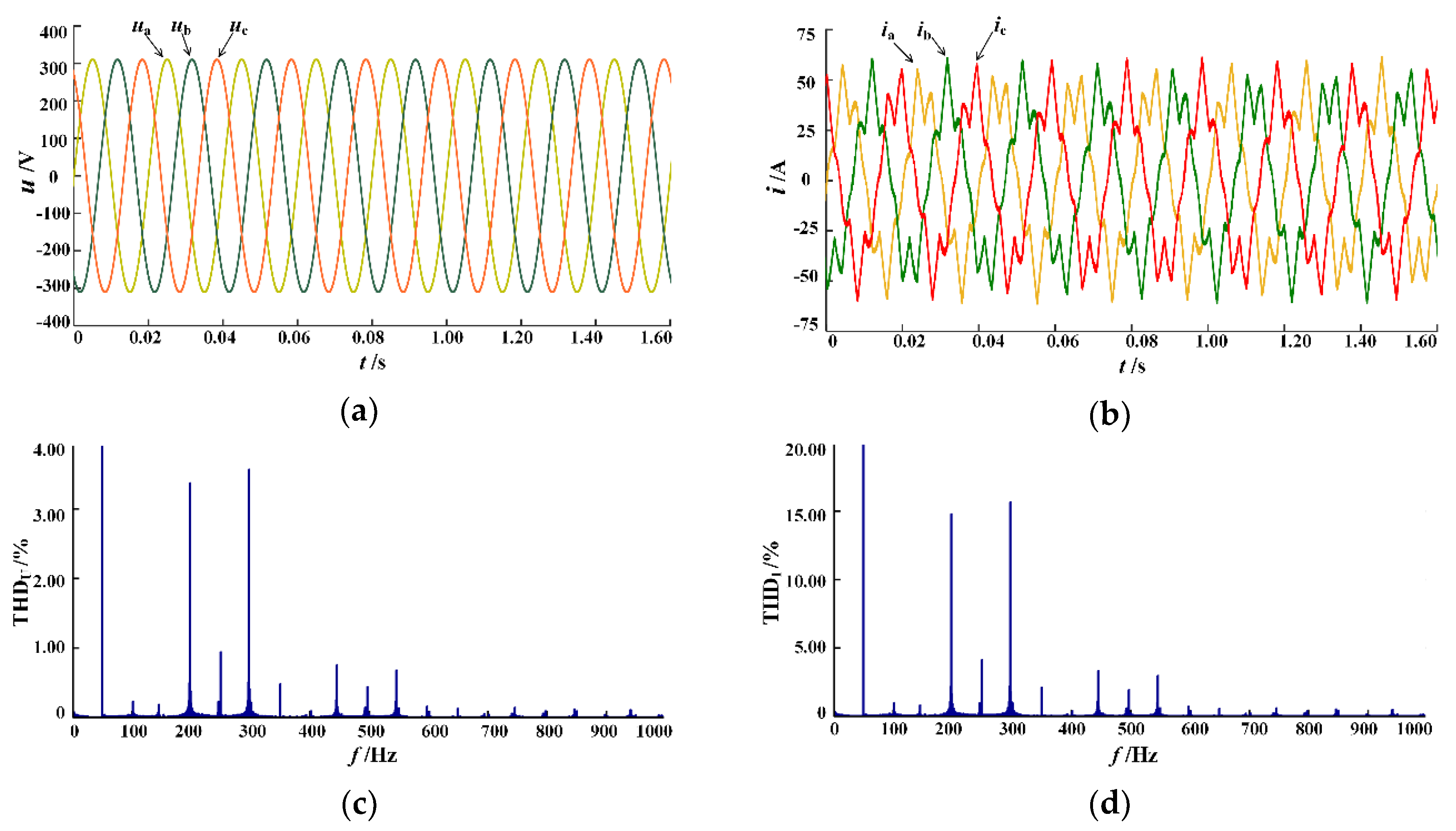
q-axis of the inverter, and the inter-harmonics with frequencies of 202.90 Hz and 302.90 Hz appear at the PV PCC. The waveforms and spectra of these inter-harmonics are presented in
Figure 13.
As illustrated in
Figure 13, significant harmonics appear at PCC and the current THD exceeds 24.50%. The simulation shows that the pulsation signals in PV inverters are the key source of the steady inter-harmonics of PV inverter outputs. The discussion below presents that the pulsation signal is generated by nonlinear self-oscillation of the “inverter-weak grid” system.
5. Discussion
According to the study above, the main characteristics of the harmonics at PCC of the PV plant are summarized as follows:
- (1)
The harmonics at PV PCC are steady-state inter-harmonics.
- (2)
The spectra of PV PCC harmonics are isolated spectral lines.
- (3)
The transition times of the harmonic appearance and fading are all very short.
- (4)
The frequencies and amplitudes of the harmonics are insensitive to external conditions.
It is proposed that the inter-harmonics at PCC of PV plant in field were generated by nonlinear self-oscillation of the “inverter-weak grid” system. A stable self-oscillation occurs inside the grid-tied PV inverters, and the harmonic frequencies did not depend on the linear characteristics of the inverters and the micro-grid. The nonlinear properties leading to nonlinear self-oscillations of the “inverter-weak grid” system are related to the integral saturation of inverter controller, PLL, hysteresis loop of grid-tied transformers, and dead-zones of IGBT-bridge of PV inverters.
The nonlinear dynamics also explain that the self-oscillations of nonlinear systems mainly include two categories: (1) periodic/quasi-periodic/chaotic oscillation with larger amplitude; and (2) weakly damped oscillation near the equilibrium with small amplitude. The nonlinear self-oscillation studied in this project belongs to the first type. In fact, the “grid-tied inverter-weak grid” system has the necessary conditions for self-oscillation: the energy conversion and energy supplement loop correspond to the invert-units and the DC sources of PV inverters; the frequency selective network corresponds to the output impedances of PV inverters, filter circuit equivalent impedances, and the line impedances of micro-grid; and the amplitude stable mechanism involves all the nonlinear properties in PV inverter-grid system. Therefore, the nonlinear self-oscillation theory proposed here reveals the essential mechanism of the harmonic generation at PV PCC in a micro-grid.
As discussed in the Introduction, the conventional methodologies of micro-grid harmonic research all include theoretical analysis, modeling, simulation and experiments. The preset of these studies was that the micro-grid and grid-tied inverters were linear systems. If any nonlinear characteristics were encountered, they should be treated by linearization. Most publications have reported from theoretical point of view, but there is no field verification in a real PV plant. In this study, the field waveforms were captured in a high-power PV plant to figure out the nonlinear self-oscillation mechanism of the harmonic phenomena in micro-grid. In fact, almost all the power quality problems in micro-grid including PV PCC harmonics come from real projects, therefore, field testing, real-time measurements and detailed data analysis are necessary for harmonic analysis and harmonic mitigations. The nonlinear self-oscillation theories proposed here and the research methodologies based on field data are worth being discussed.


