Article

Low-Power, High Data-Rate Digital Capsule Endoscopy Using Human Body Communication

SoC Design Research Group, Intelligent SoC Research Department, ICT Materials & Components Research Laboratory, ETRI, Daejeon 34129, Korea
*
Author to whom correspondence should be addressed.
Appl. Sci. 2018, 8(9), 1414; https://doi.org/10.3390/app8091414
Submission received: 13 July 2018 / Revised: 7 August 2018 / Accepted: 17 August 2018 / Published: 21 August 2018
(This article belongs to the Special Issue Body Area Networks)

Abstract

:
A technology for low-power high data-rate digital capsule endoscopy with human body communication (CEHBC) is presented in this paper. To transfer the image data stably with low power consumption, the proposed system uses three major schemes: Frequency selective digital transmission (FSDT) modulation with HBC, the use of an algorithm to select electrode pairs, and the LineSync algorithm. The FSDT modulation supports high-data rate transmission and prevents the signal attenuation effect. The selection algorithm of the electrode pair finds the best receiving channel. The LineSync algorithm synchronizes the data and compensates for data polarity during the long data transmission section between the capsule endoscope and the receiver. Because all the major functional blocks of the CEHBC transmitter can be implemented as digital logics, they can be easily fabricated using the field programmable gate array (FPGA). Moreover, this CEHBC transmitter can achieve low power-consumption and can support a relatively high data rate in spite of using its clock a few tens of MHz slower. The proposed CEHBC-TXD is the digital portion of the CEHBC transmitter that provides low-power (3.7 mW) and high data-rate (6 Mbps) performance while it supports a high-resolution image (480 × 480 byte) at 3.13 fps.

Graphical Abstract

1. Introduction

Recently, information technology (IT) developments in the medical area have been in the spotlight in the new field of biomedical engineering. Wireless capsule endoscopy (WCE) is a good example. It has been considered to be an innovative technology for the diagnosis of issues in the human digestive system (e.g., in the esophagus, stomach, small intestine, large intestine, and colon) because it is possible to avoid the disadvantages of the inspection techniques used currently for digestive organs. These disadvantages include side-effects caused by taking sleep-inducers or analgesics, and the possibility of medical accidents, such as organ perforation due to incorrect insertion of the endoscope. In addition, there is the inconvenience and fear of patients related to inserting the endoscope (a long tube) into the body. In contrast, it is possible to observe the digestive tract comfortably and without the inconvenience and risk described above when people use WCE [1,2,3].
Effective WCE was first introduced by Given Imaging Inc. (Yogneam, Israel) in 2000. The PillCam SB made by Given Imaging was approved by the food and drug administration (FDA) in 2003. It has been used as an actual medical diagnostic apparatus since then. More recently, several other kinds of WCEs have been developed and manufactured to look into the small intestine; for example, the EndoCapsule produced by Olympus Inc. (Tokyo, Japan, 2005) and the MiRoCam made by Intromedic Co. (Seoul, South Korea, 2006) [1,4].
A variety of studies have been conducted regarding WCE. One study area focuses on active capsule endoscopy, in which the posture or the motion of capsule is controlled to make observations not only in the small intestine, but also in other internal organs (the stomach and large intestine) with interior spaces that are larger than the capsules. Because the endoscope capsule is moved involuntarily through open spaces, it is difficult to obtain accurate images. Therefore, studies were conducted on active capsule endoscopy technologies to provide stable posture and movement in the various spaces to be examined [1,5,6,7,8].
Some other studies on image encoders employing image compression techniques to overcome the problem of a transceiver with limited data transfer capability have been progressed in capsule endoscopes image [1,9,10]. However, since there is a limit to the image compression method, in order to transmit the high resolution image, the transmitter supporting the high data rate is needed.
Another area of WCE study has been the exploration of several communication standards: radio frequency (RF), ultra-wide band (UWB), and human body communication (HBC). The RF systems have a disadvantage in that a significant amount of the transmitted signal is absorbed and attenuated by the human body. Therefore, the use of a high-gain antenna is required to receive the weak signals [2,3,11,12,13]. Especially, the capsule endoscope is a device that uses the human body as a signal transmission channel, rather than a general RF air channel. Since the human body is made up of various materials with different conductivities and permittivities, such as skin, muscle, fat, bone, and various organs, the speed and direction of the transmission signal varies depending on the position of the capsule [14,15]. Thus, signals transmitted outside the human body do not have isotropic characteristics. In this channel environment, complex 2D/3D array receiving antennas are used to receive signals anywhere outside the body [16,17,18]. Therefore, a technique that can select a channel more optimally while reducing the complexity is required.
On the other hand, HBC is a new communication approach for transferring baseband data using the human body as the channel medium without the need for a cable channel or RF communication channel. HBC systems have an advantage in that they can be implemented using only digital logic without complex RF blocks. This means that it is possible to manufacture a system that can be driven with low power consumption, and that should become smaller in the future by continuing the development process [19,20,21,22,23].
In this paper, we propose a new CEHBC (capsule endoscopy with HBC) system that provides low power use and a high data-rate. The CEHBC system architecture is presented in Section 2, techniques to improve performance of the CEHBC system in Section 3, and measurement and performance of the new system are described in Section 4. Discussion and conclusions are presented in Section 5 and Section 6, respectively.

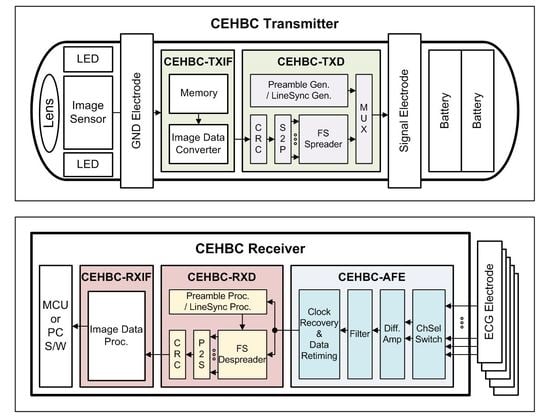
2. CEHBC System Architecture
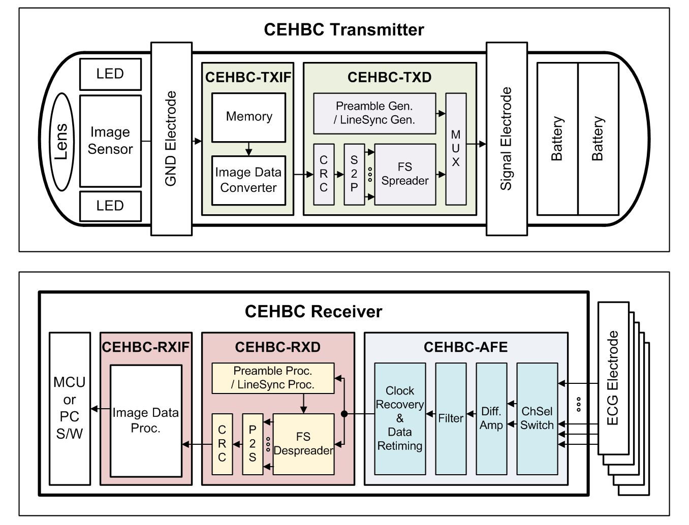
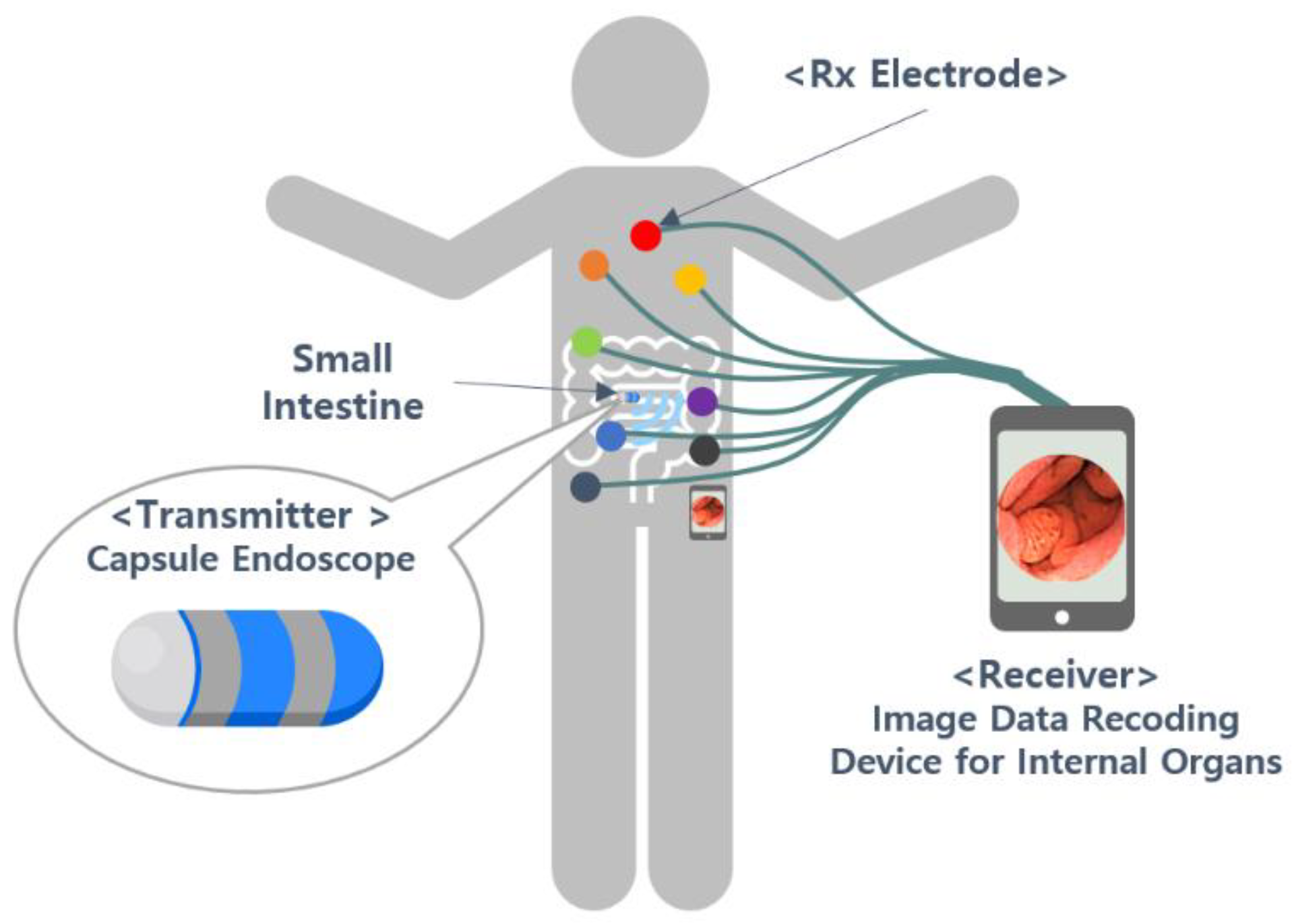
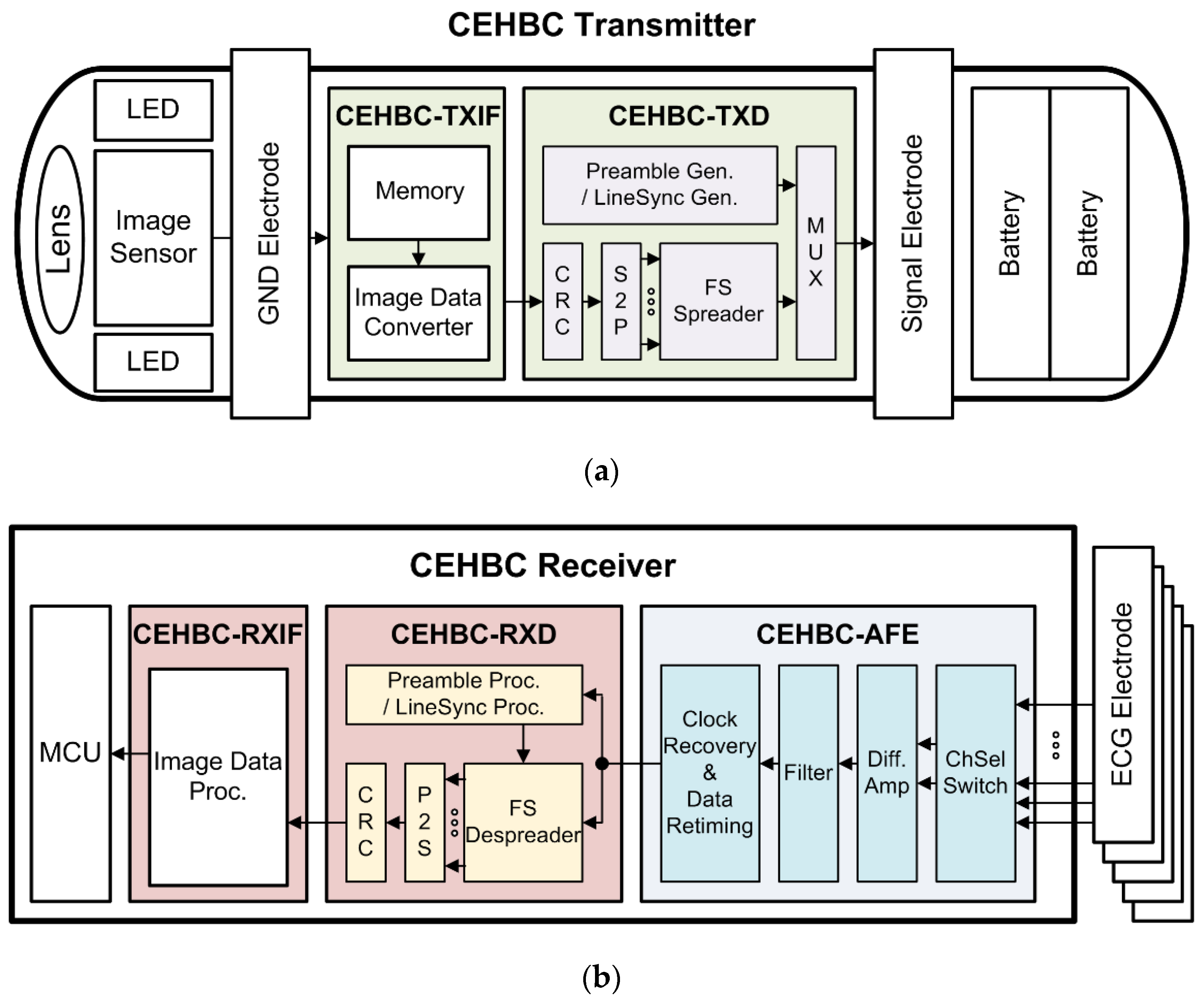
2.1. CEHBC System

In general, the WCE system is composed of one transmitter (Tx) and one receiver (Rx) with multiple receiving electrodes, because the WCE Tx capsule moves in the human body in real time. Figure 1 shows an example of the use of the WCE system. The capsule endoscope transmits the image data while moving in the body, and the receiver continually requests data reception utilizing the receiving electrodes that are attached to the human body. There are three system limitations. First, the capsule endoscope must be operable for a long time without supply of additional external power. Second, high-resolution images are required for accurate diagnosis. Third, because of the signal transmission in the body, the characteristics of the reception signal are changed by the distance and position between the capsule endoscope and the electrodes. To overcome these limitations, we proposed the following three methods for the new CEHBC system. First, we used the frequency selective digital transmission (FSDT) modulation method in the HBC to implement ultra-low power consumption and to transfer the image data stably at a high data rate. Second, we proposed using the selection algorithm to choose the best combination of electrodes among the plurality of receiving electrodes. Third, we applied the LineSync algorithm to synchronize and rematch the polarity of the signal for stable data transfer.

2.2. CEHBC Physical Structure

Figure 2 shows a block-diagram of the proposed system consisting of a CEHBC transmitter (Tx), electrocardiogram (ECG) electrodes, and the CEHBC receiver (Rx). Figure 2a is the CEHBC Tx including the lens, an image sensor, light emitting diodes (LEDs), CEHBC Tx interface (CEHBC-TXIF), the CEHBC Tx digital block (CEHBC-TXD), a signal electrode, a ground (GND) electrode, and batteries. Figure 2b is the CEHBC Rx comprising a CEHBC analog front end (CEHBC-AFE), a CEHBC Rx digital block (CEHBC-RXD), a CEHBC Rx interface (CEHBC-RXIF), and a micro controller unit (MCU).
The CEHBC Tx is inside the capsule that is inserted into the human body. The CEHBC Rx and the receiving ECG electrodes are placed on the exterior of the human body. The CEHBC Tx is capsule –shaped, and it is swallowed. On one end, the CEHBC Tx is a transparent dome-shaped lens that is able to observe the appearance of internal organs. A sensor captures the image showing the internal condition while LEDs illuminate the space near the sensor. The CEHBC-TXIF stores the image data from the image sensor in the memory and converts the raw data to the input data formats that are available in the CEHBC-TXD. The CEHBC-TXD transmits the signal that is modulated by the FSDT technique using HBC. The signal electrode radiates the Tx signal. The GND electrode serves as the reference ground for the system. Batteries supply the voltage that is needed to operate the entire endoscope.
The CEHBC-TXD transmits the image data, configuring a one-frame signal. The CEHBC-TXD is composed of a preamble generator, a LineSync generator, a cyclic redundancy check (CRC) encoder, a serial-to-parallel (S2P), a frequency selective (FS) spreader, and a multiplexor (MUX) block. The preamble generator creates the signals that are needed to acquire synchronization of the frame signal, and it selects the optimal electrode pair. The LineSync generator makes the signals that are needed to acquire synchronization, and it compensates for the polarity of each line-by-line signal that carry the image data. The CRC encoder generates parity bits to determine whether errors have occurred during the transfer of the image data. The S2P block changes the data rate to apply the FSDT techniques. The FS spreader enables the spread of data and movement of the frequency band. The multiplexer (MUX) block routes the generated data values into a specified transmission frame period.
The receiver of the capsule endoscope receives signals from a plurality of ECG electrodes attached to the exterior of the human body. The signal received from an electrode is a low-amplitude signal and it should be converted into a digital signal via the CEHBC-AFE block. The converted digital signal is input into the CEHBC-RXD block, which performs reverse digital signal processing (such as the de-spreading and demodulation) of the CEHBC-TXD block. The CEHBC-RXIF transmits the demodulated image signal to the MCU or to the PC software. It is possible to observe the image of the organ interior via the image viewer.
The CEHBC-AFE consists of a switch block, a differential amplifier, a filter block, a clock, and data recovery (CDR). The switch block changes the channel of the electrode combination to select the optimal combination of receiving electrodes. The differential amplifier amplifies the low amplitude signal. The filter block removes the noise, and the CDR processes the asynchronous data.
The CEHBC-RXD is made up of a preamble processing unit, LineSync block, FS de-spreader, parallel-to-serial (P2S) convertor block, and a CRC decoder. The preamble processing unit finds the start of the frame data received and selects the best electrode pair. The LineSync block decides the sign of the data and adjusts the synchronization of each line from the specific information data and the image data. The FS de-spreader de-spreads the data using Walsh code. The P2S converts the parallel bits to serial bits. The CRC decoder block performs error detection.
Table 1 shows the main parameters used in the CEHBC system that are presented in this paper. The CEHBC system generates the signal from the capsule inside the body and receives signals via the receiving electrodes attached to the body exterior. The CEHBC system is an example of in-body to on-body communication. The main clock of the CEHBC system uses a 32 MHz signal and the FSDT modulation method with 64 bit Walsh code. Therefore this system could spread the spectrum and generate a signal, of which the center frequency varies from direct current (DC) to 16 MHz. However, the CEHBC system utilizes the 8–16 MHz frequency band, which has less signal attenuation effect in the body. The resolution of the transfer image data is 480 × 480 byte, and it is transmitted at 3.13 f/s. One frame requires 319,440 µs of transmission time. It is possible to generate data rates up to 6 Mbps with FSDT high-rate mode modulation. The CEHBC system takes the combination structure formed with the short preamble generator output (SP) and the long preamble generator output (LPn). The SP takes on the properties of the 7-bit pseudo-random noise (PN) code; whereas the LPn has the properties of the 12-bit PN code. The combination structure has the advantage of increasing the accuracy of the receiving synchronization while having less hardware complexity. This system uses the LineSync generator, which keeps signal synchronization per line to maintain performance for data that is received over long transmission times. The LineSync uses the properties of the 5-bit PN code. It also exploits the CRC formed from a 12-bit polynomial to find out whether an error has occurred.

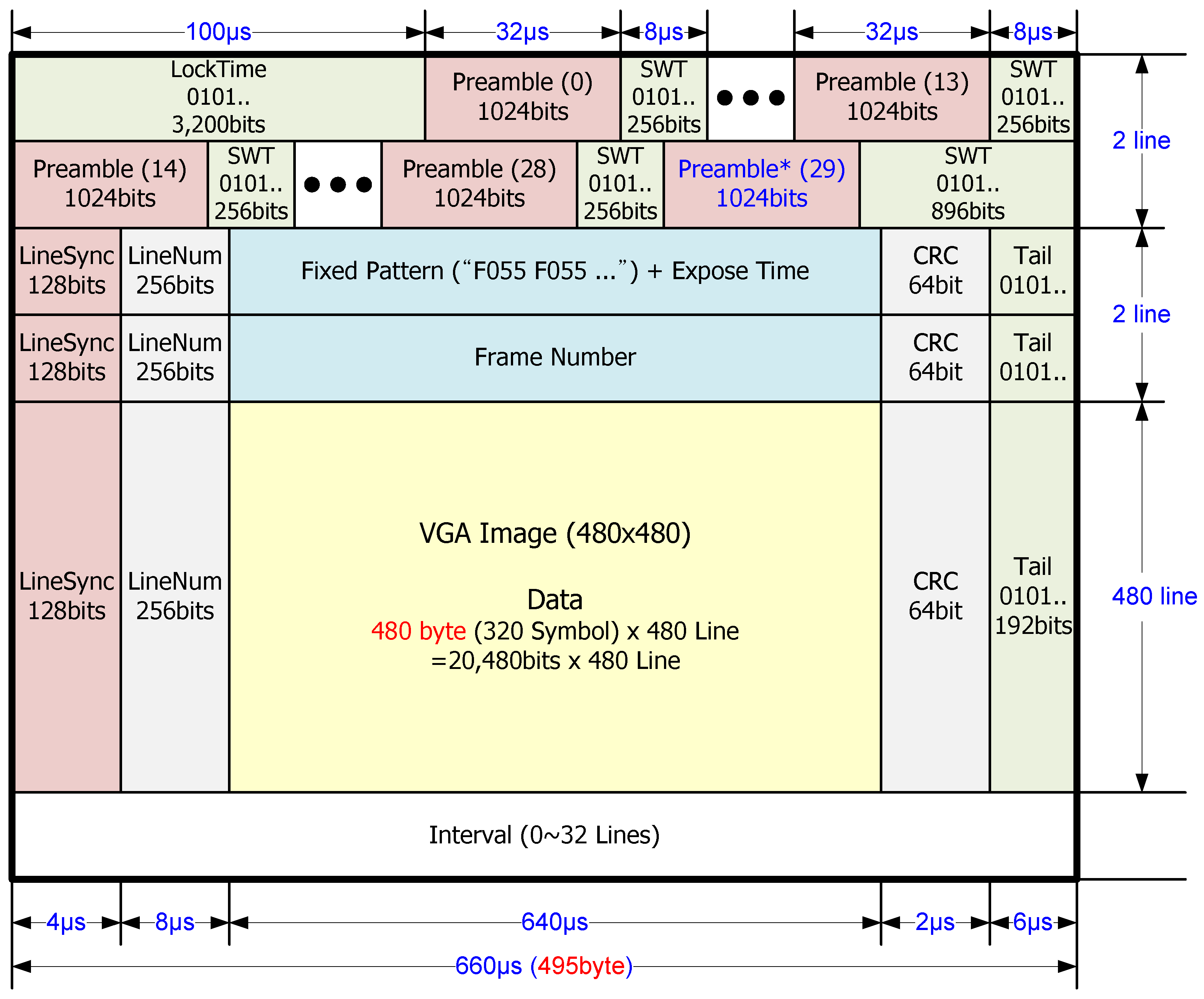
2.3. CEHBC Data Frame Structure

Figure 3 presents the data frame structure of the CEHBC system. One frame signal requires the transmission time of at least 484 × 660 µs (= 319,440 µs) to transmit the 480 × 480 byte video graphics array (VGA) image signal. Before the transfer of the specific information data and the image data, the first two lines perform the functions of driving the receiver CDR, finding the best combination of reception electrodes, and acquiring the frame synchronization. The CEHBC Rx uses the CDR, so it needs a CDR lock time section of 100 µs, which is configured with pattern data repeated with “1” and “0” bits for accurate operation of the CDR.
The CEHBC data frame is different from that of a conventional communication system. The CEHBC uses preamble sections to generate a plurality of preamble signals. This method requires selection of the optimal combination of electrodes while varying the combination of receiving electrodes. At this time, the number of preamble transmissions is determined by the number of electrodes attached to the body, and it can be expressed in Equation (1). Here, ECnum is the number of electrode pair combinations, n is the total number of electrodes, and r is the number of electrodes selected:
E C n u m = n ! r ! ( n r ) !
For example, if the number of the receiving electrode is eight, the CEHBC data frame uses 30 preamble sections that contain the 28 preamble sections (n = 8, r = 2) to test the receiving environment, one preamble section for confirmation of the selected electrode pair, and one last preamble section to indicate the last preamble transmission. In addition, switch time (SWT) sections are the physical time needed to change the reception electrodes according to the chosen combination out of the 30 options. By comparing the preamble correlation values for 28 pieces of the received signal, the CEHBC system picks the electrode pair with the maximum correlation output and is able to select the electrode pair that has the most excellent reception accuracy and sensitivity.
The LineSync section that generates the signal for synchronizing the line data is located in the first part of the line to prevent missing the synchronization during long frame intervals (3–484 lines). Then each line includes a LineNum section to indicate the line number of the transmission data, the data section, and the CRC section to determine whether an error occurred in the transmission data. The tail section indicates the last zone of the line. The data section in the third line is with the fixed pattern information to find the start of the image signal and exposure information of the camera. The data section in the fourth line is placed with the frame data information, indicating the number of the transfer frame. The data sections in the other lines are filled with 484 × 480 byte image data.

3. Techniques to Improve Performance in the CEHBC System

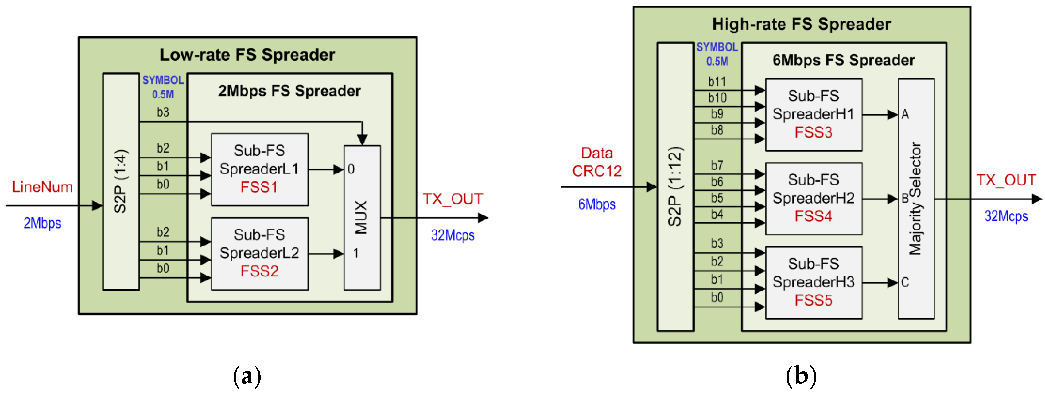
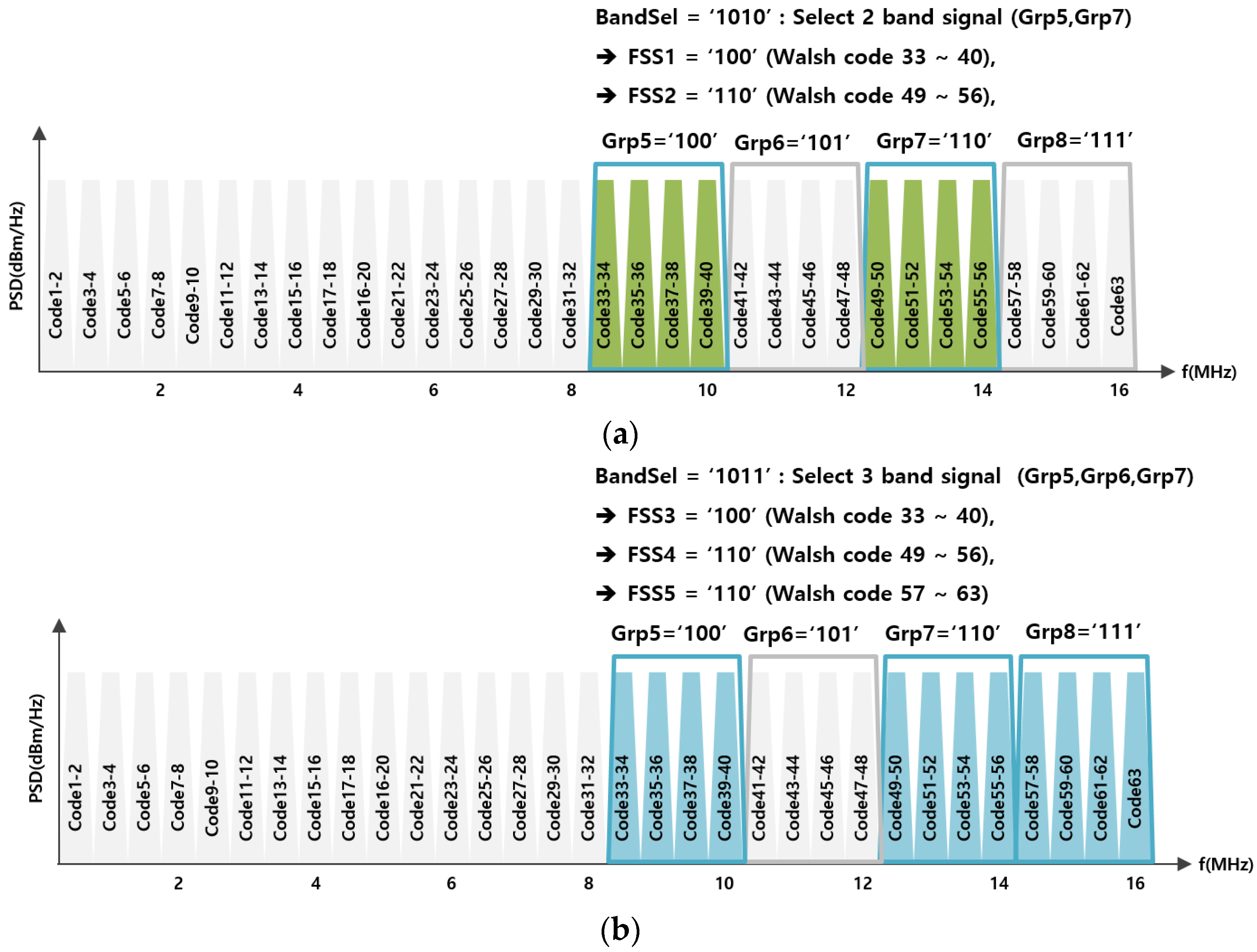
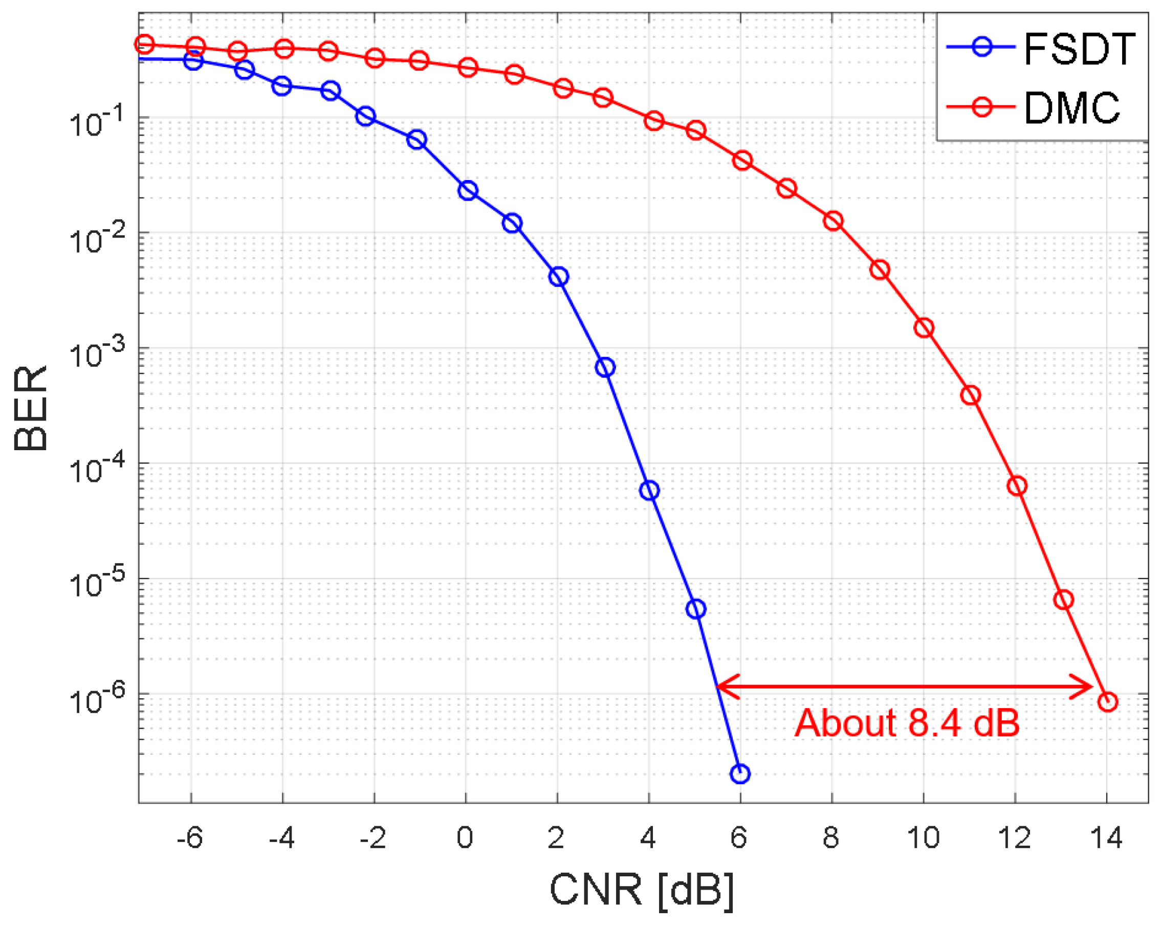
3.1. Frequency Selective Digital Transmission

The FSDT is a modulation technique that is able to spread the spectrum and to selectively move the particular frequency band using various combinations of Walsh codes. The FSDT block can be designed with digital logic only, without a digital-to-analog converter (DAC) and a radio frequency (RF) processing block. The FSDT is currently the technology that has been adopted in the IEEE 802.15.6 standard for wireless body area networks (WBAN) [19,20,21].
FSDT modulation uses the Walsh code. The Walsh code is a repetitive sequence of “1” or “0”, having a regular changing time. Therefore the Walsh code provides the fundamental frequency of each code sequence. The FSDT utilizes this frequency characteristic of the Walsh code. Figure 4 is an example of selecting the frequency bands used in the CEHBC system with the 64 bit Walsh code and FSDT modulation, and the clock operating at 32 MHz. Figure 4a exhibits the chosen two frequency bands and Walsh code ranges when using the Low-rate FS Spreader presented in this paper. Figure 4b also presents the chosen three frequency band and Walsh code ranges when using the High-rate FS Spreader. Figure 4 shows the fundamental frequency properties of the 64-bit Walsh code. In this paper, the CEHBC system used 8–16 MHz Walsh code signals intentionally because the channel attenuation effect is greatest in the vicinity of DC in the human communication channel environment. In Figure 4, the BandSel parameter is a variable that determines which band to use. The BandSel parameter comprises four bits that indicate Grp5, Grp6, Grp7, or Grp8 that represent band group parameters. If the BandSel parameter is “1010”, then the CEHBC system selects Grp5 and Grp7, and Walsh codes 33–40 and 49–56, as shown in Figure 4a. If the BandSel parameter is “1011”, then the CEHBC system selects Grp5, Grp6, and Grp7, and Walsh codes 33–40, 49–56, and 57–63, as shown in Figure 4b.
The FSDT block presented in this paper uses the revised dual-structure to support low-speed mode and high-speed mode, to improve the data transfer rate over that structure that is presented in the existing WBAN standard. When the transmission section of the LineNum data indicating the transmission line number utilizes the Low-rate FS spreader block, there is a disadvantage in terms of data transfer rate, but there is better bit error rate (BER) performance. On the other hand, when the transmission section of the image data employs the High-rate FS spreader block, there is relatively poorer BER performance than with the Low-rate FS spreader, but it is possible to transfer larger amounts of data.
Figure 5 is a block-diagram of FSDT that supports low data rate mode (Figure 5a) and high data rate mode (Figure 5b) to increase the data rate to be transmitted. The CRC parity bits added to the image data perform the S2P conversion. The Low-rate FS spreader carries out 1:4 S2P conversion and converts the data rate of 2 Mbps to the symbol rate of 0.5 Msps. The High-rate FS spreader fulfills 1:12 S2P conversion, and converts the maximum data rate of 6 Mbps into a symbol rate of 0.5 Msps. The S2P output data rate is defined with the symbol rate, having 0.5 Msps in both low-speed and high-speed mode.
In the sub-FS spreader, the combination of Walsh codes is determined by the band selection parameters (FSS1–FSS5), which determines the frequency band to be used. The Sub-FS spreader calculates the exclusive or (XOR) operation of the chosen Walsh code according to the converted S2P data values.
The Low-rate FS spreader selects the output value (either Sub-FS SpreaderL1 or Sub-FS SpreaderL2) according to the most significant bit (MSB) of the S2P output bits. The High-rate FS spreader will only output a signal with at least two identical values with the majority selector block among the three input values received from the Sub-FS SpreaderH1, Sub-FS SpreaderH2, and Sub-FS SpreaderH3. The output value of the majority selector is the same two bit value as that presented in Equation (2).
T X _ O U T = A · B + B · C + C · A
By applying FSDT techniques with Walsh code, which has fundamental frequencies from DC to half the frequency of the main clock, the CEHBC system can reduce the influence of signal attenuation to be the greatest near DC when using the human body as the medium. There is also an advantage if a user selects a specific Walsh code: the CEHBC system could shift the spread signal to a specific band without the RF frequency conversion portion. In addition, the FSDT technique performs the function of multiplying the baseband signal by the Walsh code, so that it generates a spread spectrum effect on the signal. Therefore, it is possible to restore the signal that was to be transmitted originally in the dispreading process, even if the spreading signal has been damaged by interference or noise components generated in the channel.
In addition to the FSDT method, there is a differential Manchester coding (DMC) method that uses a specific frequency band without using baseband signals near DC. The Figure 6 shows the BER performance comparison between FSDT and DMC in the additive white gaussian noise (AWGN) environment. The DMC transmits data at half the rate of the operation clock, and the FSDT proposed in this paper can transmit data with 3/16 times of the operation clock. When transmitting the 6 Mbps signal using these two modulation methods, the FSDT method shows the carrier power to noise power ratio (CNR) improvement of about 8.4 dB compared with the DMC method (at BER = 10−6).

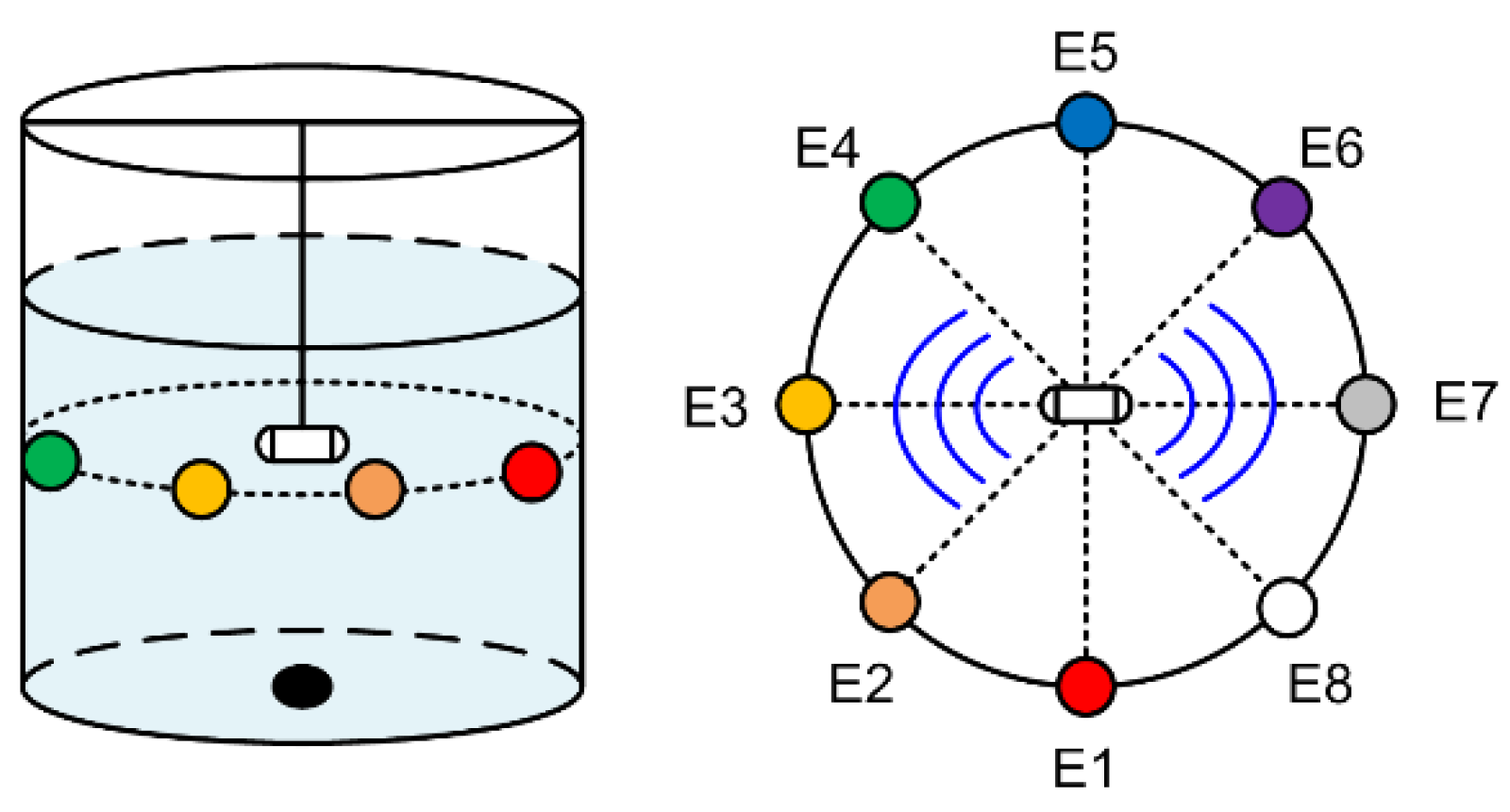
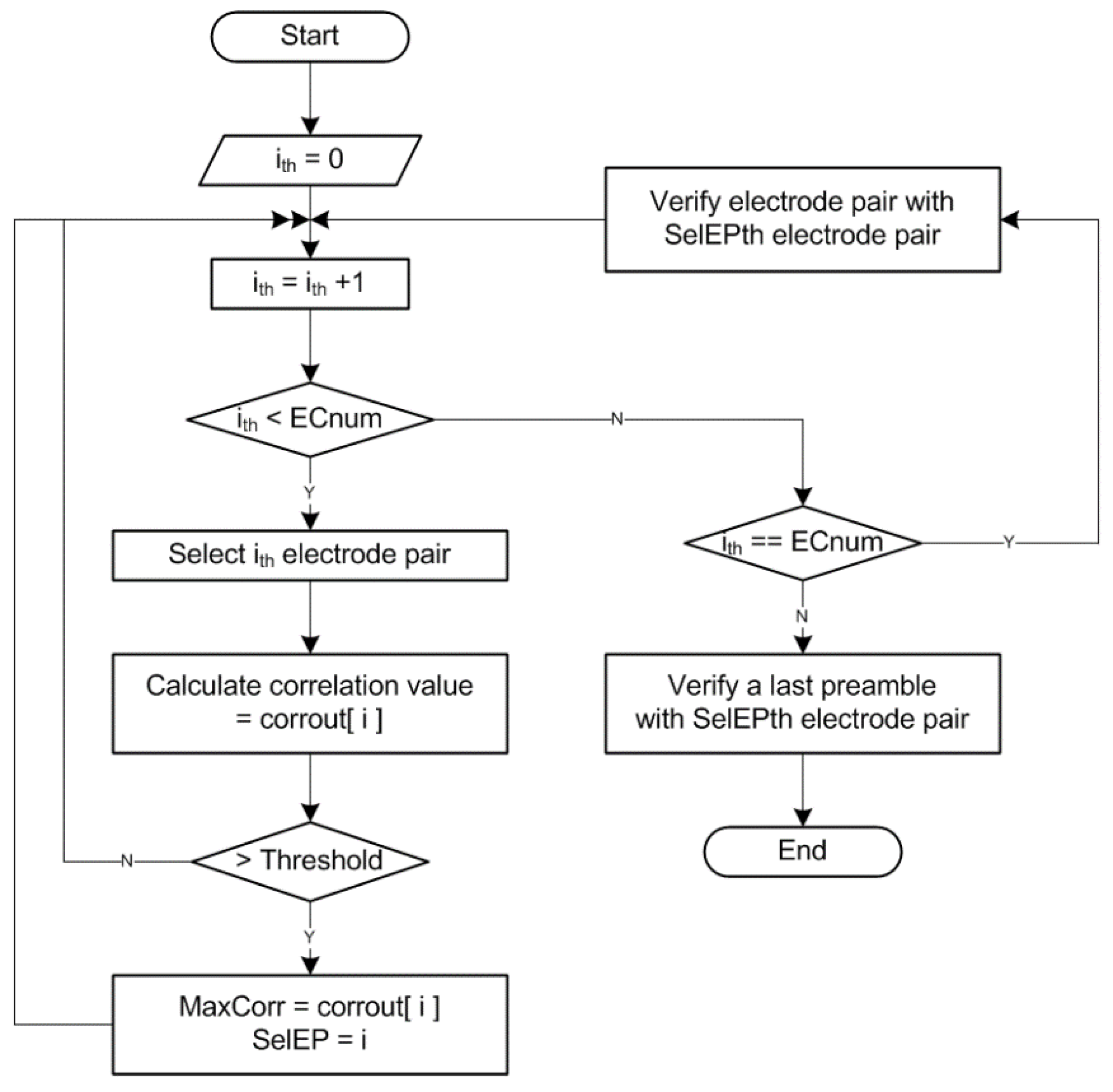
3.2. Selection Algorithm of the Electrode

The capsule endoscope moves inside the body. Therefore, the reception quality of a signal received from the receiving electrode attached to the body varies. We proposed using an algorithm to select an optimal reception electrode pair to enable stable image data transfer despite change in the position of a capsule.
The algorithm used to select the electrodes is influenced by variables such as the structure of the receiver, the number of electrodes, and the distance or position between the capsule and receiving electrodes. The CEHBC receiver presented in this paper has a differential amplifier structure to deal with noise signals. The input of the differential amplifier requires two signals corresponding to plus and minus signals. Therefore, this CEHBC receiver uses a method of selecting two electrodes. Also, the number of electrodes used in this system affects the number of combinations of electrode pairs. Plus or minus differential amplifier input signals could reverse the polarity of the differential amplifier output signal by the order of selection of the electrode pair. However, the effect on the selection order of the electrode pair is not considered in the electrode selection algorithm to reduce the complexity by half. The polarity problem of the signal is solved in the LineSync block.
Table 2 shows the combinations of electrode pairs when using the eight electrodes (E1–E8) in the CEHBC system. In this case, the combination of electrode pairs generates 28 cases (=ith case). Based on these combinations, the number of electrode pair combinations (ECnum) used in the actual system is expressed by Equation (1).
The algorithm for selection of the electrodes is affected by the position between the capsule and the electrode. Figure 7 displays the receiving condition according to the position of the capsule and electrode. While in the case of matching the capsule and the electrode pairs (E3–E7, ith = 16), each of the electrodes (without interfering) is capable of receiving the signal with the highest quality, but in the case where the capsule and the electrode pairs form at right angles (E1–E5, ith = 3), each of the electrodes receives the low quality signal offset by the opposite polarity. In addition, even in the case of ith = 16 described above Table 2, the capsule influences the polarity of the receiving signal in accordance with the location towards E3 or E7, due to the differential amplifier.
Figure 8 shows a flow chart of the electrode selection algorithm considering certain effects. For the ECnum = 28 (n = 8, r = 2), the ith variable is generated up to 0–29. During the case ith < ECnum, each pair of electrodes in each combination shown in Table 2 receives a signal from the capsule endoscope. The signal received from the electrode pair is used to calculate the correlation value. At this time, if the correlation value is bigger than a threshold Vth value, it updates the maximum correlation (= MaxCorr) and selects the ith number (= SelEP). Then, in the case of ith = ECnum, the next process is carried out to check the selected electrode pair. Last, for the case of ith = ECnum + 1, the algorithm performs a process to determine if it is the last preamble section or not.

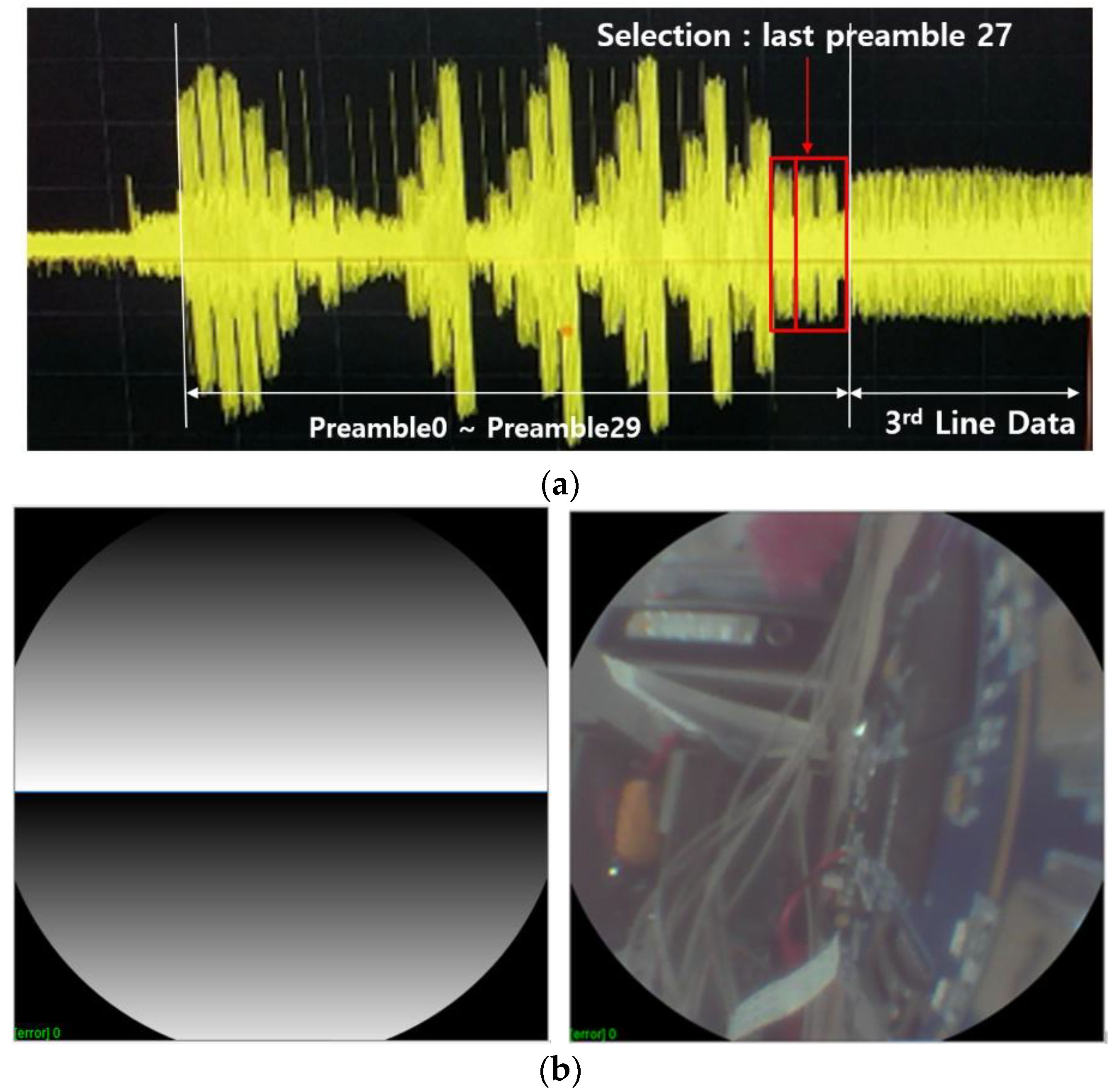
3.3. LineSync Algorithm

The LineSync section is placed at the front of each line of data, as shown in Figure 3. When receiving the individual line of data in one transmission frame, the LineSync section is used to create the data synchronization that corresponds to ±1 bit variation based on the ideal sampling signal.
The LineSync generator produces the 5 bit PN sequence signals formed with the LSp (z) = z5 + z3 + 1 polynomial. The serial signal of 32 bits is changed to serial data of 64 bits through the Manchester encoder, which can change “1” to “10” and “0” to “01”. The LineSync generator then produces the final 128 bits that are repeated twice. Here, the initial value of the PN generator polynomial is “10,000”.
By using the LineSync generator utilizing these two repeating structures, the CEHBC system has the advantage of reducing the size of the correlators in the receiver to approximately half and could acquire a large correlation value. The LineSync generator has another advantage: it can cope with the synchronization of the varied data that can occur during the interval of a long transmission frame. The location of the capsule endoscope often varies within the human digestive tract. Therefore, the polarity of the received signal could be changed depending on the situation. Thus, the LineSync generator should perform real time corrections that are conducted using the sign of the correlation values calculated by the LineSync of the receiving block.

4. CEHBC System Measurement and Performance

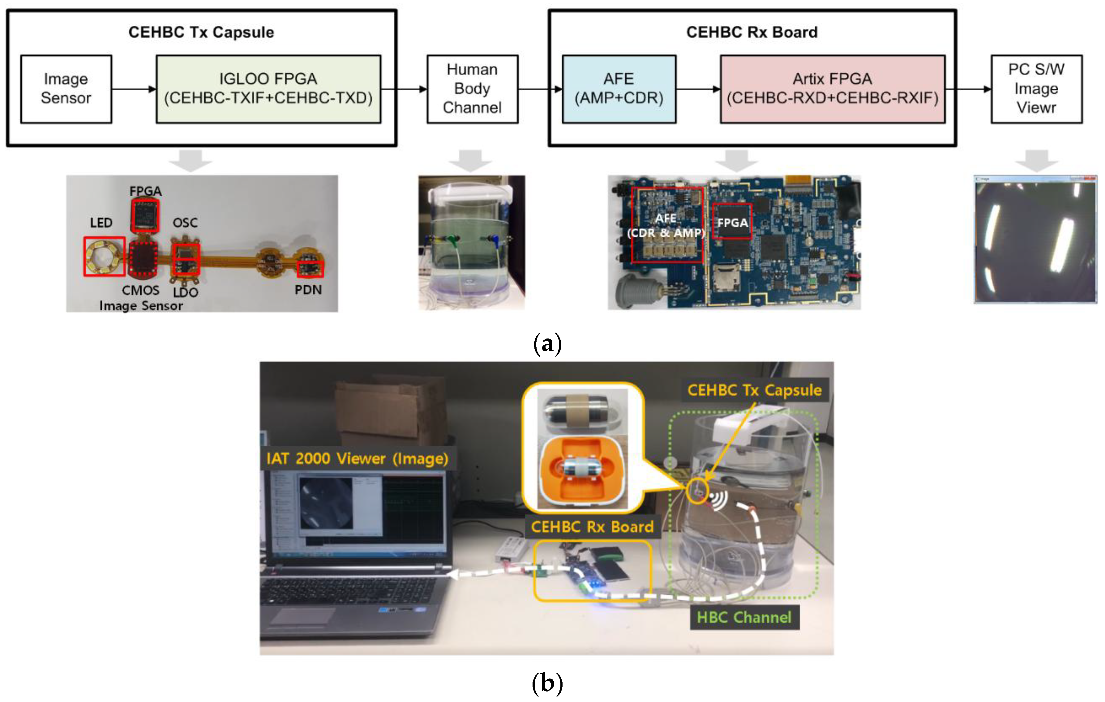
4.1. Measurement Environment of the CEHBC System

Figure 9 indicates the measurement environment of the proposed CEHBC system for performance observation. Figure 9a is a block diagram showing the configuration of the CEHBC transceiver system. Figure 9b displays the measurement environment of the CEHBC system implemented using hardware devices.
The CEHBC system included the CEHBC Tx capsule endoscope, human body channel, CEHBC Rx board, and an image viewer software. A water tank filled with saline water was used as the communication channel of the CEHBC system to realize the In-body to On-body channel environment. The CEHBC-TXIF/CEHBC-TXD and CEHBC-RXD/CEHBC-RXIF were designed with digital logic and implemented using field programmable gate array (FPGA) chips.
The output signal of the CEHBC-TXD was connected to the electrode of the capsule, which was placed in the saline tank. The signal was transmitted to the electrodes through saline channels. Signals received from the eight electrodes attached to the water tank were transferred to the CEHBC-AFE Board. CEHBC-AFE converted the received analog signal into a 1-bit digital signal using the CDR (etc.) and supplied the input data to the CEHBC-RXD. The CEHBC-RXD restored the image signal from the received signal and transferred it to the PC. The PC processed the transferred data and then displayed the image on the screen, which was captured by the image sensor.
The animal clinical experiment is needed for realistic results. However it costs a lot of money to experiment with animals. Since the performance of the capsule endoscope system should be measured by an indirect experiment before proceeding with such animal clinical experiment, we used the signal channel model with the saline tank used in the reference papers [24,25,26] below. The CEHBC capsule endoscope uses a galvanic coupling signaling system and uses a 32 MHz clock. This environment is similar to the experimental conditions presented in the reference paper [24].

4.2. Performance of the CEHBC System

Figure 10 displays the operation results transferred by utilizing the CEHBC system presented in this paper. Figure 10a is the output of the AFE amplifier. This result shows a process of testing 28 pairs of electrodes according to the selection algorithm, and displays a signal selected to transmit an image. The last preamble was selected with the electrode pair of preamble 27. The signal received from the selected electrode pair was a signal of a particular range level that was neither too large nor too small. Thus, the selected signal did not saturate, even after passing through the amplifier, and it had a state in which the signal judgment could be accurately performed. Therefore, it was confirmed that the electrode selection algorithm maintains the optimum received signal quality state.
Figure 10b is an output image that arose from the transmission of the image data. Both images in Figure 10b have a common hardware structure that supports the same f/s and power consumption, with the only difference being the TX input type. Figure 10b (left) is the known pattern used for the functional verification of the implemented CEHBC system. Figure 10b (right) is the output image utilizing the CEHBC system, for which the source data is the image taken from the complementary metal–oxide–semiconductor (CMOS) image sensor.
Table 3 exhibits the synthesized results of the CEHBC Tx digital block and CEHBC Rx digital blocks. The CEHBC Tx digital block was implemented using an Actel IGLOO AGLN125V5 FPGA (IGLOO nano version, Microsemi, San Jose CA, United States). It used about 52.25% (CEHBC-TXIF: 35.28%, CEHBC-TXD: 16.96%) of the total chip logic and consumed 6.34 mW of the power (CEHBC-TXIF: 2.63 mW, CEHBC-TXD: 3.71 mW). The power consumption value was predicted using calculating tools (Libero v11.8, Vivado March 2015). The CEHBC Rx was implemented using a Xilinx Artix7 XC7A50T FPGA (ARTIX version, XILINX, San Jose, CA, United States); it used about 16% of the total chip logic and consumed 114 mW of power.
The BER results obtained from the saline tank experiment are as follows. The diameter size of the water tank is 22 cm and height is 30 cm. The signal used in the test was the known-pattern image signal of Figure 10b (right). The variables that could control the noise were set to a direction and a distance between the electrode and the capsule endoscope. The directions of the capsule varied for each electrode (E1–E8), and the BER performance was measured according to the distance between the electrode and the capsule. Each BER performance showed the error result from receiving 100 images with 480 × 480 pixels. Table 4 represents the results of BER performance of CEHBC system. When the interval was 6 cm/11 cm, the image data was received without error. We confirmed that it was possible to receive images in all directions. When the gap was less than 1 cm, the distance between the electrode and the capsule was too close and led to the saturation condition of the signal, and made BER performance poor (>0.5). In actual clinical trials, such a condition may occur when the gap between the organs and the skin is small, such as for a child, and therefore algorithms developed in the future for processing a large received signal should be considered.
Table 5 displays a comparison of the performance of the proposed CEHBC-TXD and the existing WCE transmitters. The CEHBC-TXD presented in this paper utilizes the HBC communication scheme, while the other WCE transmitters employ a RF communication scheme using another frequency band. Because it uses HBC communication implemented mostly by digital logic, the CEHBC system has low power consumption (3.71 mW). The proposed CEHBC-TXD can support a relatively high data rate while using its clock a few tens of MHz slower. The energy consumption figure associated with the power and transmission data rate also has the small value of 0.616 nJ/bit. In addition, the results show the benefits from a high-resolution image of 480 × 480 bytes. Because the proposed method does not use an image compressor, if the data rates after image compression are compared in the structure of the papers written in the table, it can be confirmed that the data rate is the highest reported, with respect to the operating carrier frequency.
The total power consumption of the CEHBC capsule endoscope is 57.5 mW. The FPGA consisting of CEHBC-TXIF and CEHBC-TXD consumed 6.34mW to transmit the image data. The remaining blocks such as CMOS image sensor and LED etc. used 51.16 mW. Compared with the capsule endoscope proposed in [10], it can be seen that the total consumed power of the capsule of [10] is 90 mW, since three 1.5 V coin batteries are used in series and the total consumed current is 20 mA. The FPGA consumed power in the capsule endoscope of [10] is 12.42 mW. This comparison confirms that the CEHBC capsule endoscope is not only capable of high resolution image transmission, but also low power operation.
Table 6 shows the performance comparison of the capsule endoscope using HBC. Both the MiroCam capsule and the CEHBC capsule have commonalities in using the HBC to transmit baseband signals without the RF transmitter. However, the following differences exist. The main difference between the MiroCam capsule and the CEHBC capsule is that image resolution is increased. The CEHBC capsule uses a transmission method capable of image data transmission with 480 × 480 pixel, which is more than twice as much as the 320 × 320 pixel image data. This enhancement is made possible by the use of modulation methods such as the dual mode FSDT, rather than simply increasing the sampling frequency or hardware complexity. Therefore we think that the CEHBC capsule using the FSDT structure proposed in this paper is more efficient in terms of power consumption and price. The CEHBC capsules are larger and heavier than the MiroCam capsule. This is because a commercial image sensor PIXELPLUS PO8030D (digital image sensor, 2010, PIXELPLUS, Suwon-si, South Korea) is used for transmitting the 480 × 480 image data. Since it is a general-purpose image sensor product, it consumes a large amount of power and uses a large-capacity battery. Therefore, the total power of the implemented CEHBC capsule is large because of using the PO8030D image sensor. However, there is a possibility that the consumption power of the capsules will also decrease if the image sensor for capsules is used later.

5. Discussion

The methods presented in this paper have the merit of implementing the capsule endoscope configured using only digital logic. The presented capsule endoscope was implemented using the FPGA, and has the properties that the I/O voltage was 3.3 V and core voltage was 1.5 V. Therefore, it is possible to fabricate low-power capsule endoscopes using an advanced process with an operating voltage rather lower than that of FPGA. This architecture has the additional advantage in that its processes are less affected because it is implemented as digital logic. As can be seen from comparison with other capsule endoscopes, the proposed method can support a relatively high data rate in spite of using its clock a few tens of MHz slower. In the future, it is predicted that image data with a higher data rate could be transmitted if the image compression method is used.
Capsule endoscopy is currently used to diagnose the condition of the small intestine. To modern people, it is more important to judge the disease in digestive organs such as the large intestine or stomach, than to judge the disease in the small intestine. There is also a growing demand for next-generation capsule endoscopes to meet these needs. Because the large intestine or stomach has a larger space than the small intestine, this space becomes an environment in which the capsule endoscope moves rapidly and changes its position frequently [8]. As the movement time of the capsule is fast, the ability to transmit high resolution images at high speed is required. Due to a larger space than the capsule, the optimal reception channel selection and real-time acquisition function are required according to the capsule position change. The algorithm and architecture presented in this paper would be suitable for solving the requirements of next-generation capsule endoscopes.
The use of the capsule endoscopy for treatment as well as diagnosis is being studied. The capsule endoscope performs phototherapeutic treatment that illuminates blue light corresponding to Helicobacter bacteria according to pH sensing, and measures the state of the stomach [27]. These capsules still use the wireless communication system. The proposed HBC methods can be used to change this system to one that is smaller size and lower in power consumption. The technique presented in the paper is also applicable to the newly proposed medication management device [28]. We consider that it can be variously applied to new devices that transmit the bio-related information in the body in real time.

6. Conclusions

In this paper, we proposed a new, low-power capsule endoscopy system with high data rate, using HBC technology. The proposed CEHBC system uses three kinds of discrimination. The first technique is FSDT, which was used to support the low speed mode and high speed mode to increase the data transmission rate. The CEHBC system has benefits in that the receiving signal has a spread effect with the FSDT modulation that makes it less susceptible to wideband noise. The second technique involves the use of an algorithm to select the best combination of electrodes among the plurality, to select the best channel condition. The third technique involves the use of the LineSync algorithm to determine data synchronization and polarization to improve the reception accuracy of the data, even for long data transfer sections. The methods presented in this paper have the merit of implementing the capsule endoscope configured only as digital logic. The presented capsule endoscope was easily implemented using the FPGA device. Therefore, it is possible to fabricate lower power capsule endoscopes using advanced processes with lower operating voltage rather than of the FPGA. This architecture has an additional advantage that it is less affected by process variation because it is implemented as digital logic. As can be seen from comparison with other capsule endoscopes, the proposed method can support a relatively high data rate in spite of using its clock a few tens of MHz slower. In the future, it is predicted that image data with a higher data rate could be transmitted if the image compression method is used. The CEHBC-TXD system provides low power (3.7 mW) and high data rate (6 Mbps) performance while it supports high resolution images of 480 x 480 bytes at 3.13 f/s.

Author Contributions

All authors contributed to developing the measurement equipment, designing and performing measurements, data analysis, scientific discussions, and writing the paper.

Funding

This work was supported by Electronics and Telecommunications Research Institute (ETRI) grant funded by the Korean government (18ZB1200, Development of Core Technologies for Implantable Active Devices).

Acknowledgments

Thank you for the technical support of the Intromedic Corporation.

Conflicts of Interest

The authors declare no conflict of interest.

References

  1. Ciuti, G.; Menciassi, A.; Dario, P. Capsule endoscopy: From current achievements to open challenges. IEEE Rev. Biomed. Eng. 2011, 4, 59–72. [Google Scholar] [CrossRef] [PubMed]
  2. Gao, Y.; Cheng, S.-J.; Toh, W.-D.; Kwok, Y.-S.; Tan, K.-C.B.; Chen, X.; Mok, W.-M.; Win, H.-H.; Zhao, B.; Diao, S.; et al. An asymmetrical QPSK/OOK transceiver SoC and 15:1 JPEG encoder IC for multifunction wireless capsule endoscopy. IEEE J. Solid-State Circuits 2013, 48, 2717–2733. [Google Scholar] [CrossRef]
  3. Chi, B.; Yao, J.; Han, S.; Xie, X.; Li, G.; Wang, Z. Low-power transceiver analog front-end circuits for bidirectional high data rate wireless telemetry in medical endoscopy applications. IEEE Trans. Biomed. Eng. 2007, 54, 1291–1299. [Google Scholar] [PubMed]
  4. Iddan, G.; Meron, G.; Glukhovsky, A.; Swain, P. Wireless capsule endoscopy. Nature 2000, 405, 417–418. [Google Scholar] [CrossRef] [PubMed]
  5. Liu, L.; Towfighian, S.; Hila, A. A review of locomotion systems for capsule endoscopy. IEEE Rev. Biomed. Eng. 2015, 8, 138–151. [Google Scholar] [CrossRef] [PubMed]
  6. Karargyris, A.; Koulaouzidis, A. OdoCapsule: Next-generation wireless capsule endoscopy with accurate lesion localization and video stabilization capabilities. IEEE Trans. Biomed. Eng. 2015, 62, 352–360. [Google Scholar] [CrossRef] [PubMed]
  7. Woods, S.P.; Constandinou, T.G. Wireless capsule endoscope for targeted drug delivery: mechanics and design considerations. IEEE Trans. Biomed. Eng. 2013, 60, 945–953. [Google Scholar] [CrossRef] [PubMed]
  8. De Falco, I.; Tortora, G.; Dario, P.; Menciassi, A. An integrated system for wireless capsule endoscopy in a liquid-distended stomach. IEEE Trans. Biomed. Eng. 2014, 61, 794–804. [Google Scholar] [CrossRef] [PubMed]
  9. Turcza, P.; Duplaga, M. Hardware-efficient low-power image processing system for wireless capsule endoscopy. IEEE J. Biomed. Health Inf. 2013, 17, 1046–1056. [Google Scholar] [CrossRef] [PubMed]
  10. Khan, T.H.; Shrestha, R.; Wahid, K.A.; Babyn, P. Design of a smart-device and FPGA based wireless capsule endoscopic system. Sens. Actuators 2015, 221, 77–87. [Google Scholar] [CrossRef]
  11. Kim, K.; Yun, S.; Lee, S.; Nam, S.; Yoon, Y.J.; Cheon, C. A design of a high-speed and high efficiency capsule endoscopy system. IEEE Trans. Biomed. Eng. 2012, 59, 1005–1011. [Google Scholar] [PubMed]
  12. Thotahewa, K.M.S.; Redoute, J.M.; Yuce, M.R. A UWB Wireless Capsule Endoscopy Device. In Proceedings of the 2014 36th Annual International Conference of the IEEE Engineering in Medicine and Biology Society, Chicago, IL, USA, 26–30 August 2014; IEEE: New York, NY, USA, 2014. [Google Scholar]
  13. Thotahewa, K.M.S.; Redoute, J.M.; Yuce, M.R. Propagation, power absorption, and temperature analysis of UWB wireless capsule endoscopy devices operating in the human body. IEEE Trans. Microwave Theory Tech. 2015, 63, 3826–3833. [Google Scholar] [CrossRef]
  14. Brumm, J.C.; Bauch, G. On the placement of On-Body antennas for ultra wideband capsule endoscopy. IEEE Access 2017, 5, 10141–10149. [Google Scholar] [CrossRef]
  15. Goh, S.T.; Zekavat, S.A.R.; Pahlavan, K. DOA-based endsoscopy capsule localization and orientation estimation via unscented kalman filter. IEEE Sens. J. 2014, 14, 3819–3829. [Google Scholar]
  16. Nafchi, A.R.; Goh, S.T.; Zekavat, S.A.R. Circular arrays and inertial measurement unit for DOA/TOA/TDOA-based endoscopy capsule localization: Performance and complexity investigation. IEEE Sens. J. 2014, 14, 3791–3799. [Google Scholar] [CrossRef]
  17. Swar, P.; Ye, Y.; Ghaboosi, K.; Pahlavan, K. On Effect of Transmit Power Variance on Localization Accuracy in Wireless Capsule Endoscopy. In Proceedings of the IEEE Wireless Communication and Networking Conference, Shanghai, China, 1–4 April 2012; IEEE: New York, NY, USA, 2012. [Google Scholar]
  18. Hou, J.; Zhu, Y.; Zhang, L.; Fu, Y.; Zhao, F.; Yang, L.; Rong, G. Design and Implementation of a High Resolution Localization System for In-Vivo Capsule Endoscopy. In Proceedings of the 2009 Eighth IEEE International Conference on Dependable, Autonomic and Secure Computing, Chengdu, China, 12–14 December 2009; IEEE: New York, NY, USA, 2009. [Google Scholar]
  19. Hyoung, C.H.; Kang, S.W.; Park, S.O.; Kim, Y.T. Transceiver for human body communication using frequency selective digital transmission. Electron. Telecommun. Res. Int. 2012, 34, 216–225. [Google Scholar] [CrossRef]
  20. Ho, C.K.; Cheong, J.H.; Lee, J.; Kulkarni, V.; Li, P.; Liu, X.; Je, M. High bandwidth efficiency and low power consumption Walsh code implementation methods for body channel communication. IEEE Trans. Microwave Theory Tech. 2014, 62, 1867–1878. [Google Scholar] [CrossRef]
  21. Hwang, J.-H.; Kang, T.-W.; Kim, Y.-T.; Park, S.-O. Analysis on co-channel interference of human body communication supporting IEEE 802.15.6 BAN standard. Electron. Telecommun. Res. Int. 2015, 37, 439–449. [Google Scholar]
  22. MiroCam Capsule Endoscope System User Manual User Manual Intromedic Co., Ltd. Available online: https://fccid.io/VAXINTROMEDIC3/User-Manual/Users-Manual-1476111 (accessed on 13 July 2018).
  23. Hwang, W.J.; Kim, K.Y.; Choi, H.-J. Enhanced common-mode noise rejection method based on impedance mismatching compensation for wireless capsule endoscopy systems. Electron. Telecommun. Res. Int. 2015, 37, 637–645. [Google Scholar] [CrossRef]
  24. Zhang, K.; Hao, Q.; Song, Y.; Wang, J.; Huang, R.; Liu, Y. Modeling and characterization of the implant intra-body communication based on capacitive coupling using a transfer function method. Sensors 2014, 14, 1740–1756. [Google Scholar] [CrossRef] [PubMed]
  25. Hachisuka, K.; Takeda, T.; Terauchi, Y.; Sasaki, K.; Hosaka, H.; Itao, K. Intra-body data transmission for the personal area network. Microsyst. Technol. 2005, 11, 1020–1027. [Google Scholar] [CrossRef]
  26. Lee, S.H.; Lee, J.; Yoon, Y.J.; Park, S.; Cheon, C.; Kim, K.; Nam, S. A wideband spiral antenna for ingestible capsule endoscope systems: Experimental results in a human phantom and a pig. IEEE Trans. Biomed. Eng. 2011, 58, 1734–1741. [Google Scholar] [PubMed]
  27. Li, Z.; Ren, B.; Tan, H.; Liu, S.; Wang, W.; Pang, Y.; Lin, J.; Zeng, C. Capsule design for blue light therapy against helicobacter pylori. PLoS ONE 2016, 11, 1–10. [Google Scholar] [CrossRef] [PubMed]
  28. Akyildiz, I.F.; Pierobon, M.; Balasubramaniam, S.; Koucheryavy, Y. The internet of bio-nano things. IEEE Commun. Mag. 2015, 53, 32–40. [Google Scholar] [CrossRef]
Figure 1. Example of the use of the wireless capsule endoscopy (WCE) system to explore the state of the small intestine.
Applsci 08 01414 g001
Figure 2. Block-diagram of the proposed capsule endoscopy with a human body communication (CEHBC) system: (a) CEHBC transmitter; (b) CEHBC receiver.
Applsci 08 01414 g002
Figure 3. Data frame structure of the CEHBC system.
Applsci 08 01414 g003
Figure 4. Example of selecting the frequency bands used in the CEHBC system: (a) Two frequency band and Walsh code range chosen when using the low-rate frequency selective (FS) spreader; (b) Three frequency band and Walsh code range chosen when using the High-rate FS spreader.
Applsci 08 01414 g004
Figure 5. Block-diagram of the dual-mode frequency selective digital transmission (FSDT): (a) Low-rate FS spreader; (b) High-rate FS spreader.
Applsci 08 01414 g005
Figure 6. Bit error rate (BER) performance comparison between FSDT and differential Manchester coding (DMC).
Applsci 08 01414 g006
Figure 7. The received condition according to the position of the capsule and the electrode.
Applsci 08 01414 g007
Figure 8. Flow chart of the electrode selection algorithm.
Applsci 08 01414 g008
Figure 9. Measurement environment: (a) Block-diagram of the CEHBC transceiver system for measurement; (b) Measurement environment of the implemented CEHBC system.
Applsci 08 01414 g009
Figure 10. Operation results of the proposed system: (a) Output of the analog front end (AFE) amplifier; (b) Image results received by the CEHBC system: (left) Image data using a known pattern, (right) Image data using the CMOS image sensor.
Applsci 08 01414 g010
Table 1. Parameters of capsule endoscopy with a human body communication (CEHBC) system.
ParametersDescription
applicationInbody-to-Onbody (capsule endoscopy)
main clock frequency32 MHz
modulationdirect digital frequency selective digital transmission (64 b Walsh code)
frequency band 8–16 MHz
resolutionimage data 480 × 480 byte (3.13 f/s)
frame Length319,440 µs
data ratemaximum 6 Mbps
preamblecombination of short preamble and long preamble
linesync5-bit pseudo-random noise (PN) code
cyclic redundancy check (CRC)CRC-12 polynomial
Table 2. Combinations of electrode pairs when using the eight electrodes in the CEHBC system.
Case ithSelected Electrode 1Selected Electrode 2Case ithSelected Electrode 1Selected Electrode 2
0E1E214E3E5
1E1E315E3E6
2E1E416E3E7
3E1E517E3E8
4E1E618E4E5
5E1E719E4E6
6E1E820E4E7
7E2E321E4E8
8E2E422E5E6
9E2E523E5E7
10E2E624E5E8
11E2E725E6E7
12E2E826E6E8
13E3E427E7E8
Table 3. Synthesis results of CEHBC digital blocks.
CEHBC Tx field Programmable Gate Array (FPGA) Block (CEHBC-Tx Interface (TXIF) & CEHBC-Tx Digital (TXD))CEHBC Rx FPGA Block (CEHBC-RXD & CEHBC-RXIF)
field programmable gate array (FPGA)Actel IGLOO
AGLN125V5-CS81
Xilinx Artix 7
XC7A50T-CSG324
synthesis and Download toolLibero v11.8Vivado 2015.3
logic sizeCEHBC-TXIF Core: 1084 of 3072 (35.29%)
CEHBC-TXD Core: 521 of 3072 (16.96%)
Resource Utilization (LUT)
5231 of 32,600 (16.05%)
input/output voltage levelLVCMOS 3.3VLVCMOS 3.3V
power consumptionCEHBC-TXIF:2.63 mW
CEHBC-TXD:3.71 mW
114 mW
main clock frequency32 MHz32 MHz
Table 4. BER performance of the CEHBC system.
Distance between Electrodes and Capsule EndoscopeThe Direction of the Capsule Endoscope towards the Electrode
E1E2E3E4E5E6E7E8
6 cm00000000
11 cm00000000
Table 5. Performance comparison of wireless capsule endoscopy (WCE) transmitters.
2007 [3]2013 [2]2015 [10]This
ApplicationCapsule Endoscopy
data rate before image compression1 Mbps3~20 Mbps8 Mbps6 Mbps
image compressionX(lossy)(lossless/lossy)X
compression ratio93% (1:15)>75% (1:4)
data rate after image compression1 Mbps1.34 Mbps2 Mbps6 Mbps
communicationRFRFRFHBC
carrier frequency2.4 GHz920/925 MHz2.4 GHz32 MHz
modulationAmplitude Shift
Keying
(ASK)
Quadrature
Phase
Shift
Keying
(QPSK)
Gaussian Minimum
Shift
Keying
(GMSK)
Frequency Selective Digital Transmission
(FSDT)
technologyCMOS
250 nm
CMOS
180 nm
FPGA
130 nm
(AGLN125V5)
power consumption7.925 mW2.5 mW3.7 mW
energy consumption7.925 nJ/bit1.865 nJ/bit0.616 nJ/bit
resolution640 × 480320 × 240
160 × 120
128 × 96
480×480
frame rate3 f/s55 f/s3.13 f/s
Table 6. Performance comparison of the capsule endoscope using human body communication (HBC).
SpecificationMiroCam [1,22]CEHBC Tx Capsule
communicationhuman body communication
image sensorcustomized CMOS image sensor with 320 × 320 pixel array)PIXERPLUS PO8030D VGS single chip CMOS image sensor with 640 × 480 pixel array
pixel102,400 (=320 × 320)230,400 (=480 × 480)
frame rate3 frames/s3.13 frame/s
data rate3 Mbps6 Mbps
field of view150 degrees
battery3 V, 160 mAh Coin battery
battery life11 h8.3 h
lighting6 LEDs6 LEDs
size11 × 24 mm13 × 27 mm
weight3.4 ± 0.05 g6.1 g

