Study on the Dynamic Mechanical Properties of Viscoelastic Materials Based on Asymmetrical Sandwich Beams

School of Marine Science and Technology, Northwestern Polytechnical University, Xi’an 710072, China
*
Author to whom correspondence should be addressed.
Appl. Sci. 2018, 8(8), 1359; https://doi.org/10.3390/app8081359
Submission received: 11 July 2018
/
Revised: 4 August 2018
/
Accepted: 8 August 2018
/
Published: 13 August 2018
(This article belongs to the Section Mechanical Engineering)
Abstract
:A modified estimation method for the dynamic mechanical properties of viscoelastic materials via asymmetrical sandwich specimens is presented. In contrast to the traditional vibrating cantilever beam test method (VCBTM), the proposed method allows asymmetrical base beams in sandwich specimens. Based on the complex stiffness method, complex parameters are introduced for general sandwich configurations. Calculation formulas for loss factor and shear modulus of the core material are presented. The effectiveness of this approach is validated numerically and experimentally by analysis of one symmetrical sandwich beam specimen and two specimens with asymmetrical thicknesses and materials. It is shown that dynamic mechanical parameters of the core material can be obtained regardless of sandwiches’ symmetry. The proposed method breaks the symmetrical criteria for sandwich specimens and may provide a wider application to measure viscoelastic materials’ dynamic properties.
1. Introduction
Benefiting from the high damping performance, viscoelastic materials have been widely utilized in aerospace and vehicle transport industries. The dynamic mechanical properties of viscoelastic materials such as loss factor, Young’s modulus and shear modulus are essential parameters in the investigations of structural vibration and acoustic. The measurement of dynamic parameters of viscoelastic materials have attracted much attention.
In the area of mechanical vibration and shock, traditional test methods to determine the dynamic mechanical properties of viscoelastic materials include the resonance method, the cantilever shear beam method, the dynamic stiffness method [1] as well as the vibrating cantilever beam test method (VCBTM) [2], etc. Specifically, to measure the damping properties of materials, the system damping of structures are usually tested firstly. Methods for the determination and identification of the damping parameter include the decay rate method [3,4], the half-power bandwidth method [5], the power input method [6,7], the circle-fit method [8] and the integral method [9], etc.
Viscoelastic materials are usually non-self-supporting and are embedded into composite structures. Hence determining the mechanical parameters of viscoelastic materials becomes the inverse problem of calculating the dynamic characteristics of composite configurations. Among the dynamic research on the composite structures, Kerwin and Ungar [10,11] firstly accomplished the damping analysis of constrained-layer damped structures employing the complex stiffness method as well as the strain energy method. Base on the complex stiffness method, Derby and Ruzicka [12] evaluated the loss factor and resonant frequency of multilayered structural composites with viscoelastic materials. The modal strain energy method (MSEM) is nowadays widely used to investigate the vibration characteristics of composite structures [13,14], yet it’s hard to apply the MSEM in the damping identification of materials. Recently some new methods have been presented to determine the damping and stiffness characteristics of structures. The force analysis technique was used by Ablitzer et al. [15] to identify the stiffness and damping properties of both homogenous and heterogeneous structures, establishing a straight forward relationship between the material properties and displacement field. The complex wavenumber method was developed by Mcdaniel and Dupont [16] to estimate frequency-dependent loss factor of a beam with arbitrary transient loading. Subsequently, Rak et al. [17] employed this method to determine structural damping property over discrete but regularly spaced frequency with the experimental validation based on cantilever beam test. The wavenumber method was also implemented by Ichchou et al. [18] to obtain effective sandwich structural properties and identify the equivalent models. The displacement field method was developed by Cherif et al. [19] to estimate the loss factor of two-dimensional orthotropic structures based on a scanning laser vibrometer measurement. The inverse identification approach was implemented by Barkanov et al. [20] to characterize the viscoelastic layers in sandwich panels and was used by Sun et al. [21] to evaluate the mechanical parameters of viscoelastic materials.
Among the various test methods, the vibrating cantilever beam test method (VCBTM) has been widely used to determine materials’ dynamic mechanical properties because of its simple and feasible maneuverability. It is remarkable that test methods based on microscale cantilevers are also widely utilized to extract the mechanical properties of materials and structures in small dimensions. Guo et al. [22] determined the Young’s moduli of amorphous Cu–Zr thin films by force-deflection measurements of microscale cantilevers on the basis of atomic force microscope (AFM) technique. Ghidelli et al. [23] extracted the elastic moduli of both layers of bilayer microcantilevers from stiffness measurements by nanoindentation technique. They also determined the residual stress of double clamped bilayer micro beams, which plays an important role in surface effects on microscale structures. Yun [24] evaluated the Young’s modulus of a silicon nitride thin film based on microcantilever resonance tests with ultrasonically actuations. When compared with other techniques to investigate micro materials’ mechanical behavior, including bending [25], ultrafast laser metrology [26] and bulge tests [27], micocantilever techniques can provide simpler procedures or enhanced detectability. The aforementioned micro beam test methods are enlightening, however their applications are still confined to microscale materials such as thin films. Besides, they cannot be used to obtain the damping characteristics. For bulk-like materials, the VCBTM is a convenient and effective method by which both loss factors and moduli can be extracted from modal vibration data using bilayer or sandwich beam specimens.
For non-self-supporting materials, such as viscoelastic materials, materials to be measured are usually embedded into sandwich beams when employing the VCBTM [2]. Yet the available solution formulas in reference [2] are only applicable for symmetrical sandwich beam specimens. Consequently, the dimensions and resonant frequencies of the individual base beams must match. It has been found that in a batch of 20 to 30 beams there are only several pairs of beams that meet the criteria [2]. This may bring about a waste in the preparation and selection of test specimens.
In this paper, a modified estimation method is proposed to determine the dynamic mechanical properties of shear-damped viscoelastic materials using asymmetrical sandwich specimens. As an extension of the VCBTM, residual stress in the interface of different layers will not be considered since shear deformation in the viscoelastic core is predominant during the vibration of sandwiches. This method will be helpful to avoid the waste in the process of specimen preparation and can enrich the experimental data. In the theoretical modeling section, analytical formulas for calculating the loss factor and shear modulus of materials are given for general sandwich beam specimens based on the complex stiffness method. Detailed operations in the measurement process using the proposed method are described. Simulations are subsequently accomplished to validate the effectiveness of this method. Verification experiments are then carried out with three kinds of different sandwich beam specimens being measured: one symmetrical specimen, one asymmetrical specimen with base beams of different thicknesses and one asymmetrical specimen with base beams consisting of different materials. Finally, comparisons and discussions of the experimental results are presented.
2. Theoretical Modelling
2.1. General Sandwich Beam Specimens
Figure 1 illustrates the section sketch of a sandwich specimen. The face sheets are elastic base layers, referred to as layer 1 and layer 3, respectively. The core layer is the viscoelastic material to be measured, referred to as layer 2. Distinguished from traditional sandwich specimens in the VCBTM, in this study the materials and thicknesses of base layers can be different. As shown in Figure 1, the neutral surface of the first layer is chosen as the reference datum line; is the distance from the neutral surface of the configuration to the reference datum line; is the distance from the th layer’s neutral surface to the center of the first layer; is the thickness of the th layer.
The neutral surface of the sandwich can be determined by
where is the extensional stiffness of the th layer and is the product of the Young’s modulus and the section area. For a beam of the width , .
The bending stiffness of the sandwich configuration can be expressed in the complex form
where is the complex stiffness, is the effective bending stiffness, and is the structure or system loss factor. The system loss factor can be determined by .
In the damping analysis of constrained sandwich structures in references [10,11,12], the complex shear parameter , the geometrical parameter were introduced as
where is the loss factor of the damping material and is the effective shear parameter. The effective shear parameter of the sandwich configuration is determined by , where is the shear modulus and is the flexural wavenumber, .
and
where , , represent the uncoupled, coupled and transfer flexural rigidities (or bending stiffnesses) of the composite structure, respectively. The uncoupled bending stiffness and transfer bending stiffness are given by and .
The complex coupling parameter was also introduced in reference [12], which satisfies the following expressions for constrained-layer sandwich structures
where
The real part and imagine part of the complex coupling parameter are respectively expressed as
Here we introduce the bending stiffness ratio as the ratio of the effective bending stiffness and the uncoupled bending stiffness of sandwich structures, which is expressed as
According to Equations (5) and (6), the relationship of the stiffness ratio and the complex coupling parameter can be expressed as
Combining Equations (9), (10) and Equations (12), (13), the loss factor and the effective shear parameter can be obtained as follows
As for cantilever beam specimens, the modal flexural wavenumbers can be achieved by [2]
where is the length of the beam and is the coefficient for mode of clamped-free uniform beam, , , , , , and , for > 3.
Equation (18) implies that beams of identical lengths undergo the same modal wavenumbers. Thus when the VCBTM is used to determine the dynamic mechanical properties of viscoelastic materials, the wavenumbers of the base beam specimens and sandwich beam specimens are approximately equal. According to the definition expression of the flexural wavenumber, we arrive at . Thus the bending stiffness ratio of the tested sandwich beam specimen can be obtained by
where and represents the areal density and the resonant frequency of the th layer respectively, represents the resonant frequency of the sandwich specimen.
For sandwich test beam specimens, the bending stiffness of the damping layer is far smaller than the bending stiffness of the elastic base layers. Thus Equation (17) can be rewritten as
where represents the density of the th layer.
In Equation (18), the densities, thicknesses of each layer, and the resonant frequencies of the base beams and sandwich specimens are the parameters to be tested during the vibration cantilever beam test.
According to the definition formulas Equation (4), the geometrical parameter of a sandwich beam can be expressed as
According to the definition expression of the effective shear parameter, the shear modulus of the cantilever sandwich beam can be obtained by
Substituting Equation (20) into Equation (15), we arrive at
where is the modal system loss factor of the sandwich beam.
Equation (21) and Equation (22) are calculation formulas of damping loss factor and shear modulus respectively for general sandwich beam specimens.
After the material parameters and resonant frequencies are tested, the bending stiffness ratio and geometrical parameter can be achieved by Equation (18) and Equation (19) respectively. The structure loss factor can be obtained from the frequency response curve of the sandwich specimen. Subsequently, the loss factor and shear modulus of the core material can be calculated by Equation (21) and Equation (22). What needs to be stressed is that the symmetry of specimens does not restrict the application of the aforementioned formulas.
When asymmetrical sandwich beam specimens are chosen, the material parameters and resonant frequencies of both the base beams should be measured before the measurement of the sandwich beam. This is the only operation to be added when compared with the traditional test method using symmetrical sandwich specimens.
2.2. Symmetrical Sandwich Beam Specimens
When symmetrical sandwich specimens are chosen, the equations to determine the dynamic mechanical properties can be simplified. With respect to symmetrical specimens, , , and . The bending stiffness ratio and geometrical parameter can be obtained as follows:
where and are the thickness ratio and density ratio respectively, and , .
If we define and , after some manipulation, Equation (21) and Equation (22) can be rewritten as
It’s evident that Equations (25) and (26) are in the same form as the Equations (8) and (9) in the referred standard [2]. Hence, the simplified calculation formulas is valid for symmetrical sandwich beams.
3. Simulations and Discussions
To study the effectiveness of the proposed method, the following simulations are accomplished with respect to symmetrical and asymmetrical cantilever sandwich beams. When the beam test technique is employed, the thickness of the base beam is usually chosen as 1 mm–3 mm and the metal is often chosen to be steel or aluminium. As illustrated in Figure 2, here we consider three kinds of sandwich beams: beam 1 with 1-mm-thick and 1.2-mm-thick steel base beams; beam 2 with one 1-mm-thick steel base beam and one 1-mm-thick aluminium beam; beam 3 with two symmetrical 2 mm steel base beams. The sandwich beams are all of 250 mm length and has one identical 0.1-mm-thick damping layer.
Firstly, the geometrical parameter can be obtained according to its definition formulas Equation (4). When the effective bending stiffness, uncoupled bending stiffness and system loss factor are achieved by the Kerwin-Ungar theory [10,11], the modal characteristics (modal frequencies, bending stiffness ratios and structure loss factors) can be achieved. Thus the modal loss factor and shear modulus of the viscoelastic material can be obtained according to Equations (21) and (22), respectively.
In the following sections, two kinds of damping material setting conditions are studied.
3.1. Constant Damping Model
When the aforementioned three kinds of beams are studied, firstly constant damping and elastic properties are considered. The material loss factor is given as 0.6 and the shear modulus is set as 1 MPa. The loss factors and shear moduli of the damping material are calculated by the proposed method based on the modal data of the aforementioned three sandwich beams. The comparison is shown in Figure 3.
Figure 3 shows that accurate results of modal loss factors and shear moduli can be evaluated using the two kinds of asymmetrical beams (beam 1 and beam 2), just as the traditional symmetrical beam (beam 3) does. It can also be observed that the three kinds of cantilever sandwich beams have similar modal frequencies and similar modal dynamic mechanical properties. The reason lies in that beams in this analysis have similar flexural rigidities, structure loss factors as well as identical beam length.
3.2. Frequency-Dependent Viscoelastic Model
In practice, the dynamic mechanical properties of viscoelastic materials are usually frequency-dependent. To validate the effectiveness of the proposed method for common viscoelastic materials, one damping material with frequency-dependent loss factor and shear modulus is studied. The loss factor and shear modulus of the sandwich core material are given as follows
Calculated results of the modal loss factors and shear moduli by the proposed method using the aforementioned three kinds of sandwich beams are illustrated and compared in Figure 4.
It can also be observed from Figure 4 that both asymmetrical and symmetrical sandwich specimens can determine the frequency-dependent dynamic properties at the same precision.
Since there is no limitation in the frequency domain for complex parameters defined in the theory, the present method can be applied to viscoelastic materials that is either frequency-dependent or frequency-independent. It offers the possibility of providing various kinds of sandwich specimens to enrich the experimental results.
4. Experimental Validation
4.1. Experimental Apparatus
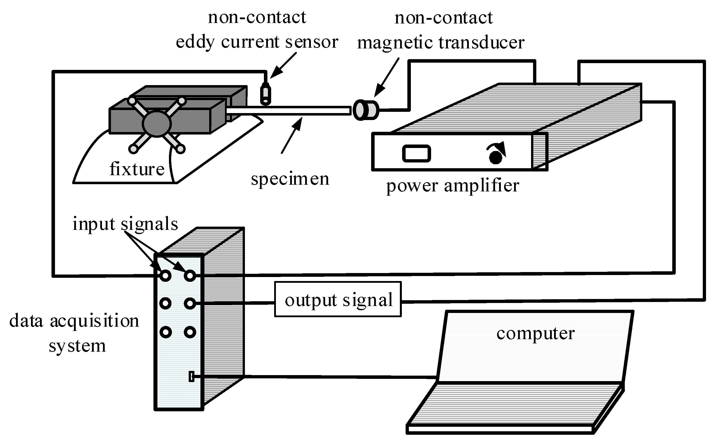
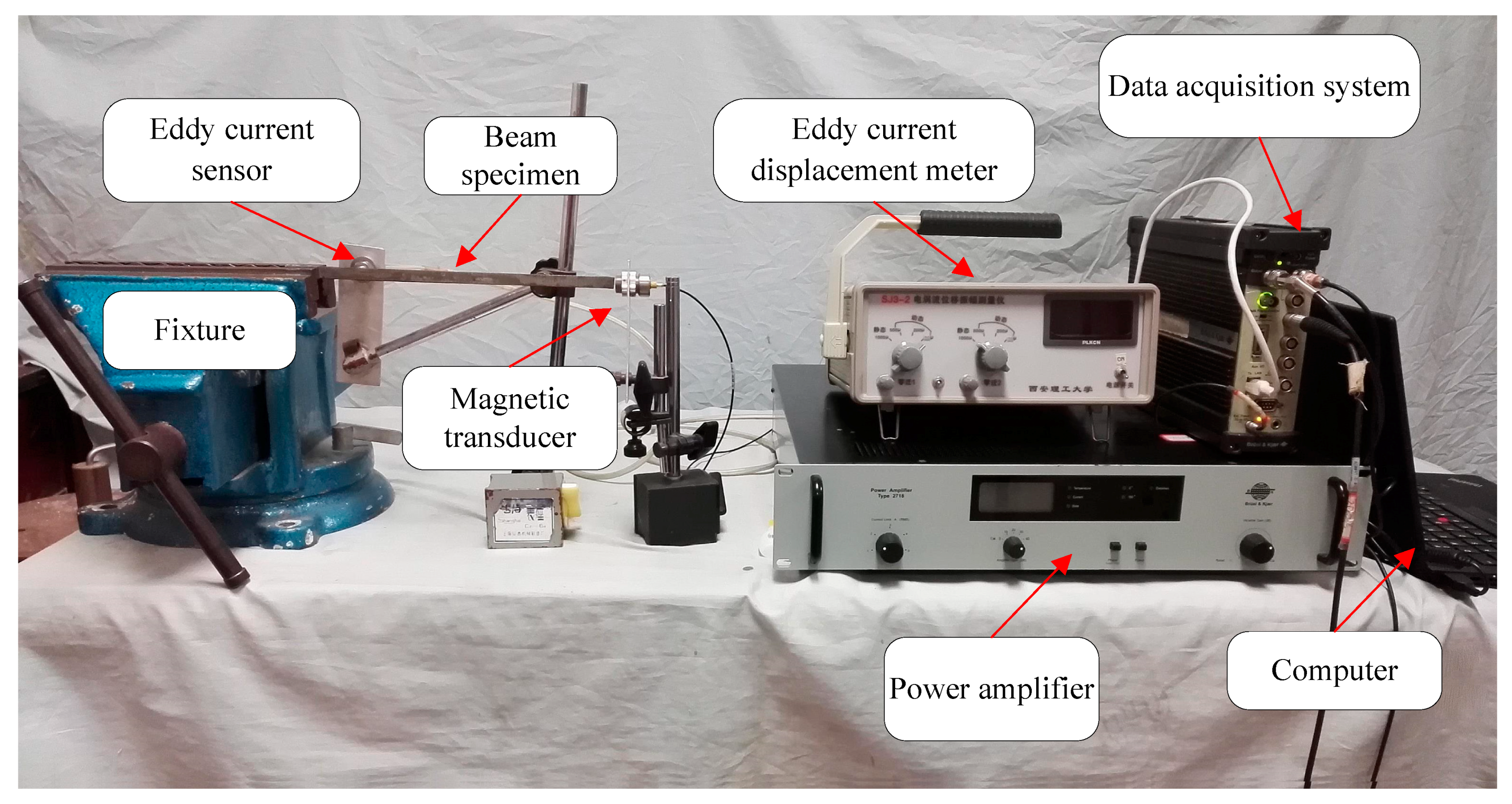
Verification experiments are conducted based on the VCBTM, with an experiment system shown in Figure 5 and Figure 6. The generation signal is a random white noise signal created by the data acquisition system (B&K 3560B) and is processed by the power amplifier (B&K 2718). A non-contact magnetic transducer (B&K MM0002) is used to generate the free end of the specimen. A non-contact eddy current sensor (SJ3–2) is used to pick up the displacement response signal of the beam. The data acquisition system (B&K 3560B) processes the time domain signals into frequency response signals to obtain the modal data. All experiments are conducted in the room temperature of 26 °C.
4.2. Test Specimens
As shown in Figure 7, three different sandwich beam specimens are prepared to measure the dynamic mechanical properties of one self-adhesive viscoelastic damping material (VDM). The asymmetry types include the asymmetry of base beams’ thickness and the asymmetry of materials. The short asymmetrical specimen is 180-mm-long and consists of a 0.90-mm-thick steel base beam and a 1.02-mm-thick steel base beam; the long asymmetrical specimen is 240 mm long and contain a 0.97-mm-thick steel substrate beam and a 0.90-mm-thick aluminium substrate beam; the long symmetrical specimen is 240 mm long and is composed of two 0.97-mm-thick steel base beams. All the test specimens are 10 mm wide and has identical self-adhesive VDM core with the thickness of 0.5 mm. The densities of the steel, aluminium and VDM are measured as 7830 kg/m3, 2710 kg/m3, 1600 kg/m3, respectively.
To simulate the cantilever boundary condition, thick root sections of 25 mm length, 16 mm thickness are designed. Aluminium sheets with the same thickness of the sandwich cores are adhered to the root spacers between the adjacent root sections, aiming at giving firm and ideal cantilever support.
4.3. Experimental Results
4.3.1. Normalized Displacement Frequency Responses
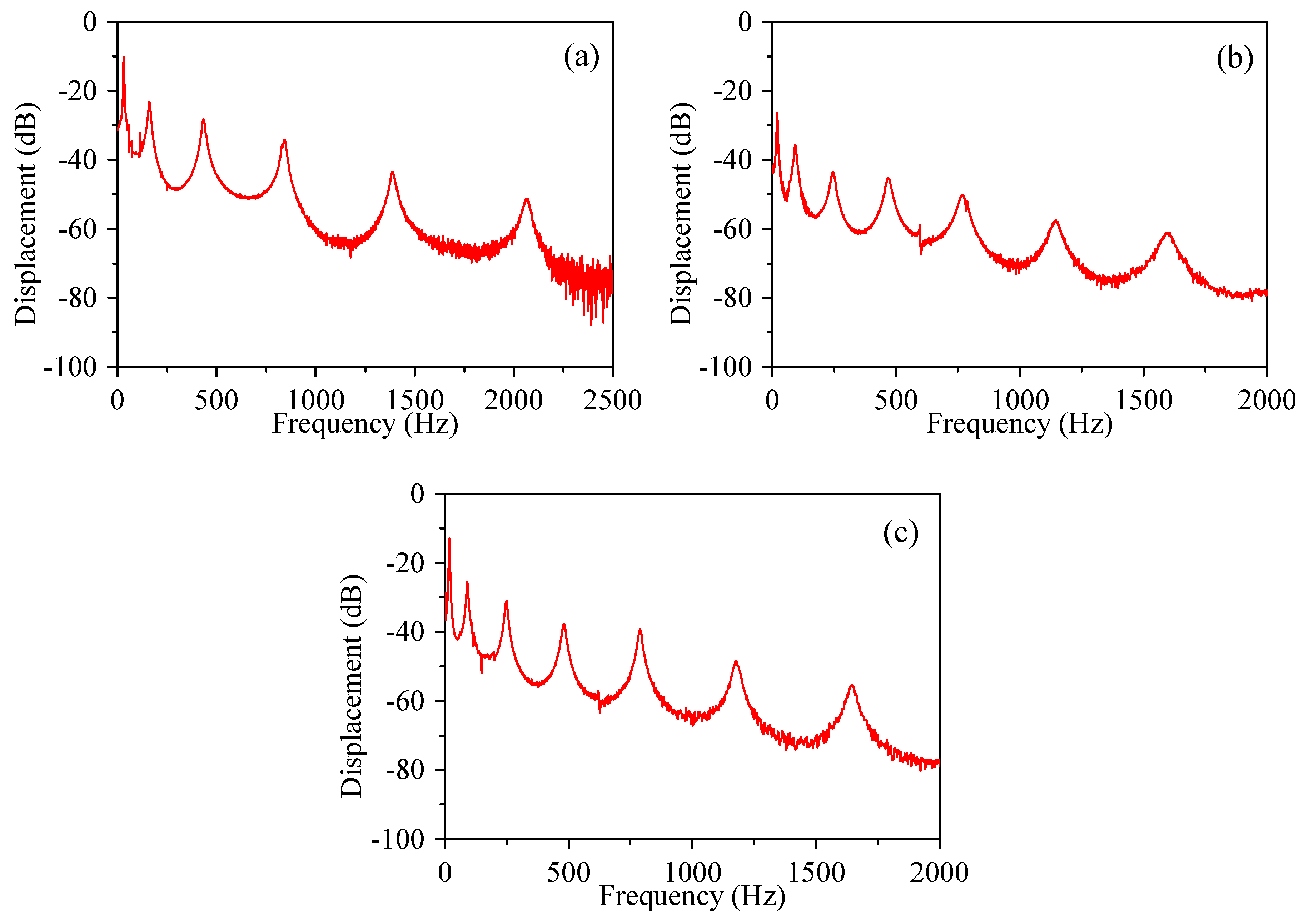
Firstly, broadband excitation are applied onto the free ends of three sandwich specimens. The displacement responses around the clamped ends are obtained and analyzed by the fast Fourier transform (FFT). At this procedure, the frequency resolution set up of the FFT is not high in order to reduce the average time of signal processing. The normalized frequency response curves are illustrated in Figure 8, from which modal data can be obtained.
As shown in Figure 8, the first six resonant peaks of the short asymmetrical beam are measured, ranging from 1 Hz to 2500 Hz. The first seven resonant peaks of the long asymmetrical beam as well as the long symmetrical beam are obtained, ranging from 1 Hz to 2000 Hz. Since the frequency resolution and average times of the FFT are set relatively low in this procedure, only approximate modal frequencies can be extracted. It can also be observed that more signal burrs arise in the high frequency domain, revealing that vibrations of sandwich beams are harder to be excited and signal noises are more apparent at the higher modes. Hence, the number of FFT average times in high frequency should be given much bigger than those in low frequency in the following analysis.
Since the theoretical modeling of the VCBTM is based on the assumption of infinite boundary, this approximation is acceptable only at the higher modes [2] and it has been the practice to ignore the first modal results. This practice is also complied with in this study.
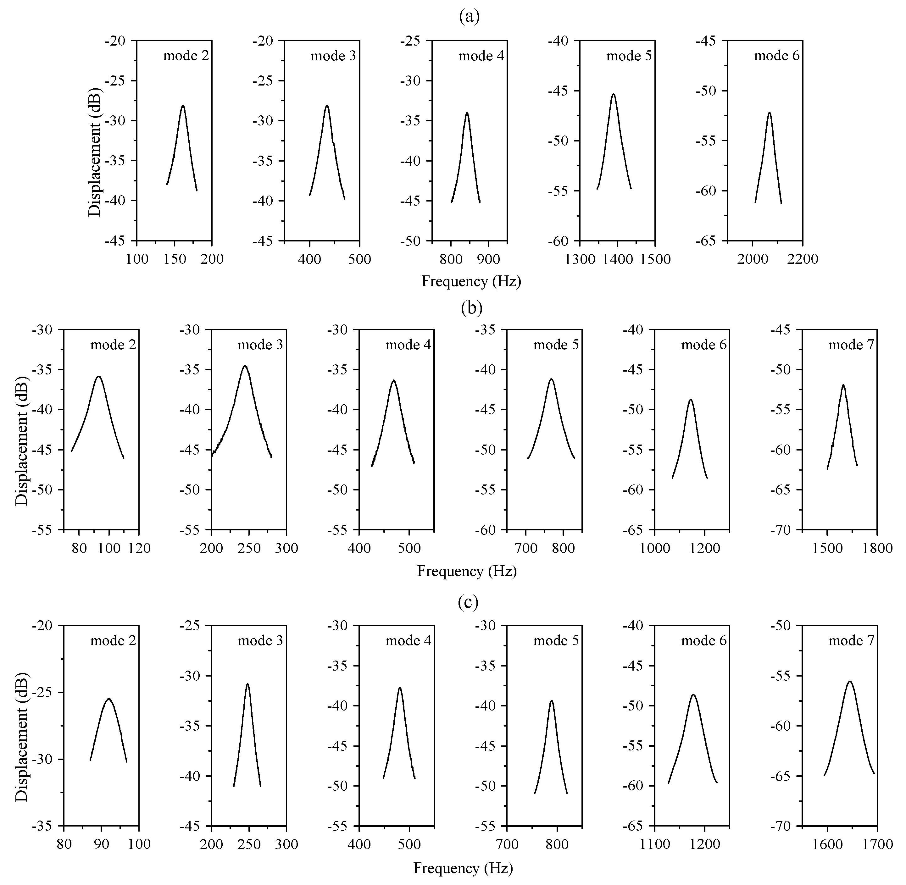
According to the previously obtained approximate modal frequencies, narrow band excitation signals are subsequently applied for each mode. Meanwhile, higher frequency resolutions and bigger number of average times are set up for the FFT. In this way, displacement responses at resonances with more details are guaranteed. Figure 9 reports the normalized frequency response curves under narrow band excitations for three sandwich beams. Figure 9a shows resonant responses of the short asymmetrical beam at the second to the sixth modes. Figure 9b,c show the second to the seventh mode data for the long asymmetrical beam and long symmetrical beam, respectively.
It is obvious that frequency response curves in Figure 9 are smoother and clearer than those obtained in the broadband excitation procedure. It can also be observed that the modal frequency response curves are approximately symmetric and nonlinear phenomenon does not arise at resonant peaks. As for the response curve from each mode, an approximate difference of 10 dB is guaranteed between the response at resonance and the value at the lowest or highest frequency. The response curve from the second mode of the long symmetrical beam seems to be an exception, with only 5 dB difference in the narrow frequency band. This is due to the appearance of interference signals at low frequency. Anyway, 5–10 dB response differences are quite enough to extract modal loss factors by the half-power bandwidth method or other damping identification methods. Hence, accurate modal frequencies and other modal characteristics can be extracted from narrow band frequency response curves.
4.3.2. Modal Frequencies and Loss Factors of Sandwich Specimens
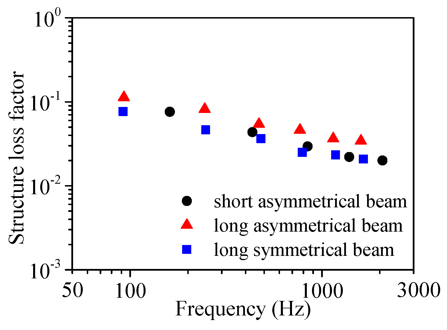
The integral method proposed by Guo [9], which can be used to process linear and nonlinear response data, is employed to calculate modal loss factors by the narrow band experimental data. Tested modal frequencies from the second to the sixth modes of the short asymmetrical sandwich specimen and modal frequencies of its base beams are listed in Table 1. Tested modal frequencies from the second to the seventh modes of the long asymmetrical and symmetrical sandwich beam specimens and modal frequencies of their base beams are listed in Table 2 and Table 3 respectively. Tested structure loss factors of three beam specimens are diagramed in Figure 10. As listed in the tables, the modal frequencies over 1 kHz are obtained by the frequency resolution of 1 Hz to reduce the FFT average time, meanwhile higher frequencies resolutions are set at lower modal frequencies.
As illustrated in Figure 10, the modal loss factors of the short asymmetrical beam are 0.076, 0.044, 0.030, 0.022, 0.020, accordingly. The tested modal loss factors of the long asymmetrical sandwich specimen are 0.113, 0.081, 0.054, 0.046, 0.036, 0.034, accordingly. The tested modal loss factors of the long symmetrical sandwich specimen are 0.077, 0.046, 0.036, 0.025, 0.0234, 0.0209, accordingly. The modal structure loss factors of three beam specimens are mostly in the range of 0.01–0.1 which is easy to be determined from the response at resonance. It can also be observed that the structure loss factors all decrease with frequency from the second mode.
4.3.3. Modal Shear Moduli and Modal Loss Factors
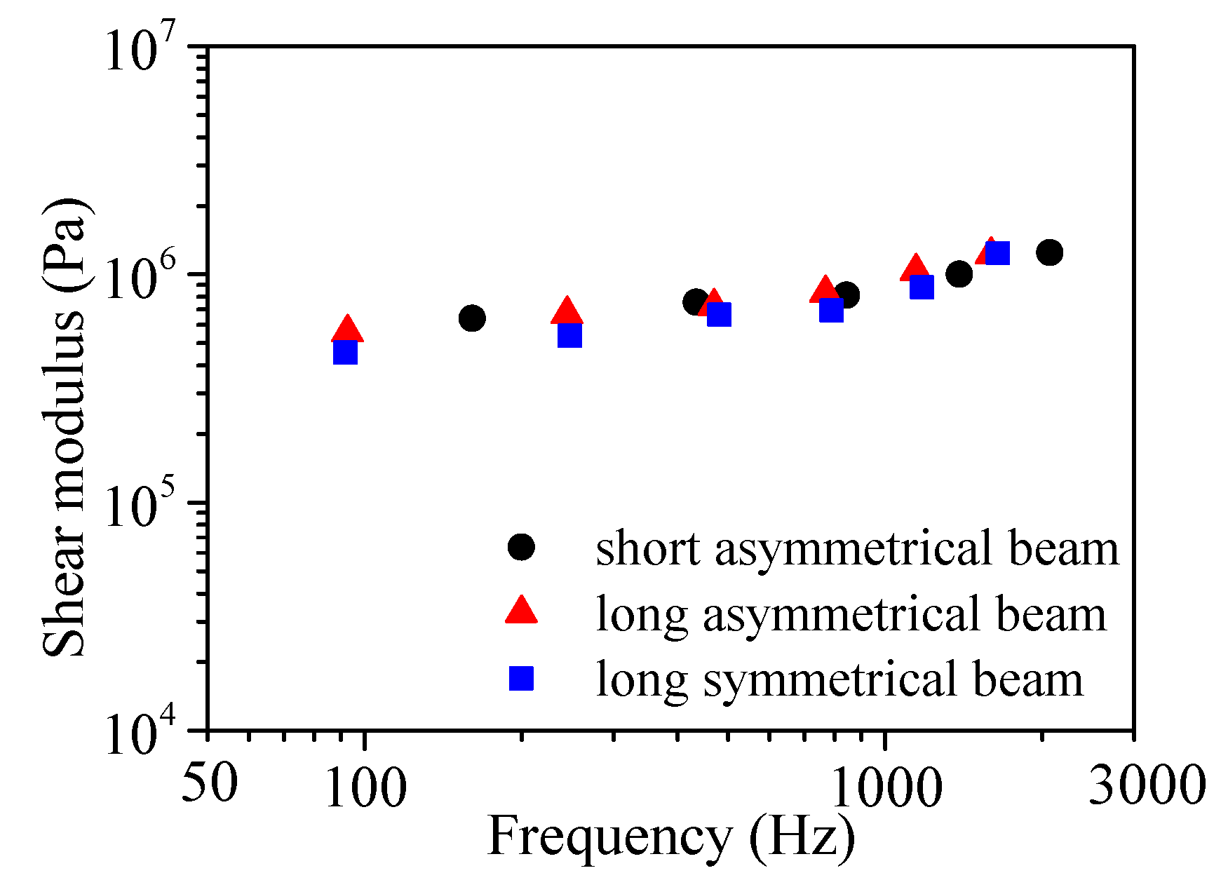
With the modal frequencies of base beams measured, the shear moduli of base beams can be achieved. With known densities, thickness and modal frequencies, the bending stiffness ratio and the geometrical parameter can be determined by Equations (18) and (19), respectively. And then according to Equations (21) and (22), the frequency-dependent dynamic mechanical properties of the VDM can be determined. The modal loss factors and shear moduli obtained by three sandwich specimens are compared and illustrated in Figure 11 and Figure 12, respectively.
It can be seen from Figure 11 and Figure 12 that the frequency-dependent trend of the measured dynamic mechanical properties of the VDM is obviously concordant, despite that the results are obtained by three distinguished sandwich specimens. This coincidence manifests the effectiveness of the proposed method. Both the shear modulus and loss factor increase with increasing frequency in the range of 50–2500 Hz, which implies that in this frequency range the VDM is in the transition region at the temperature of 26 °C. Due to the same length and similar bending stiffness, modal frequencies measured by the long asymmetrical and long symmetrical sandwich specimens are similar at the same mode number. It can also be observed that sandwich beam specimens with various compositions and lengths can enrich the tested results, which denotes to estimating modal properties at different frequencies.
5. Conclusions
A modified evaluation method has been presented in this paper for the dynamic mechanical properties of viscoelastic materials via asymmetrical sandwich specimens, and some improvement has been made for the vibrating cantilever beam test method (VCBTM). Calculation formulas and operation points for the measurement of shear modulus and loss factor of viscoelastic materials have been given. With the asymmetry of thickness and material of base beams taken into account, theoretical and experimental studies have been carried out to verify the effectiveness of the proposed method.
Simulation results have validated that asymmetrical sandwich beams can be used to calculate frequency-dependent loss factor and shear modulus of materials accurately just as symmetrical sandwiches do. It is also confirmed by experimental results that concordant frequency-dependent trends of dynamic properties of the viscoelastic damping material could be achieved regardless of specimens’ symmetry. The permission of asymmetrical materials and thickness avoids the repeated examinations to minimum the dimensional tolerance and modal frequency difference between two base beams. When compared with the traditional VCBTM, the only operation to be added is that material parameters and resonant frequencies of both base beams should be measured before the measurement of the sandwich beam specimen.
In conclusion, the present method breaks the restriction of preparing identical base beams in the traditional VCBTM. It can prevent the waste of time in the critical specimen selection and is propitious to diversity test specimens enriching the experimental data. Thus the proposed method is in favor of broadening the application of the VCBTM to measure dynamic mechanical properties of viscoelastic materials.
Author Contributions
Conceptualization, W.Q.Q.; Data curation, W.Q.Q.; Formal analysis, W.Q.Q.; Funding acquisition, W.M.Q; Investigation, W.Q.Q.; Methodology, W.Q.Q; Project administration, W.M.Q; Resources, W.M.Q.; Software, W.Q.Q.; Supervision, W.M.Q.; Validation, W.Q.Q.; Visualization, W.Q.Q.; Writing–original draft, W.M.Q.; Writing–review & editing, W.M.Q.
Funding
This research was funded by [the Shenzhen Science and Technology Innovation Committee] grant number [JCYJ20170306154350796].
Conflicts of Interest
The authors declare no conflict of interest.
References
- ISO. Mechanical Vibration and Shock—Characterization of the Dynamic Mechanical Properties of Visco-Elastic Materials; ISO 18437; ISO: Geneva, Switzerland, 2005. [Google Scholar]
- ASTM. Standard Test Method for Measuring Dynamic Mechanical Properties of Materials; ASTM E. 756705; ASTM: West Conshohocken, PA, USA, 2005; pp. 1–14. [Google Scholar]
- Bies, D.A.; Hamid, S. In situ determination of loss and coupling loss factors by the power injection method. J. Sound Vib. 1980, 70, 187–204. [Google Scholar] [CrossRef]
- Bloss, B.C.; Rao, M.D. Estimation of frequency-averaged loss factors by the power injection and the impulse response decay methods. J. Acoust. Soc. Am. 2005, 117, 240–249. [Google Scholar] [CrossRef] [PubMed]
- Yin, H.P. A new theoretical basis for the bandwidth method and optimal power ratios for the damping estimation. Mech. Syst. Sig. Process. 2008, 22, 1869–1881. [Google Scholar] [CrossRef]
- Carfagni, M.; Pierini, M. Determining the Loss Factor by the Power Input Method (PIM), Part 2: Experimental Investigation with Impact Hammer Excitation. J. Vib. Acoust. 1999, 121, 422–427. [Google Scholar] [CrossRef]
- Liu, W.B.; Marks, S.E. Experimental and analytical estimation of loss factors by the power input method. AIAA J. 2007, 45, 477–484. [Google Scholar] [CrossRef]
- Srikanth, N.; Gupta, M. Damping characterization of magnesium based composites using an innovative circle-fit approach. Compos. Sci. Technol. 2003, 63, 559–568. [Google Scholar] [CrossRef]
- Guo, Z.W.; Sheng, M.P.; Ma, J.G. Damping identification in frequency domain using integral method. J. Sound Vib. 2015, 338, 237–249. [Google Scholar] [CrossRef]
- Kerwin, E.M. Damping of flexural waves by a constrained viscoelastic layer. J. Acoust. Soc. Am. 1959, 31, 952–962. [Google Scholar] [CrossRef]
- Ungar, E.E. Loss factors of viscoelastically damped beam structures. J. Acoust. Soc. Am. 1962, 34, 1082–1089. [Google Scholar] [CrossRef]
- Derby, T.F.; Ruzicka, J.E. Loss Factor and Resonant Frequency of Viscoelastic Shear-Damped Structural Composites; NASA CR 1269: Springfield, VA, USA, 1969. [Google Scholar]
- Li, J.; Narita, Y. Analysis and optimal design for the damping property of laminated viscoelastic plates under general edge conditions. Compos. B Eng. 2013, 45, 972–980. [Google Scholar] [CrossRef]
- Adessina, A.; Hamdaoui, M.; Xu, C. Damping properties of bi-dimensional sandwich structures with multi-layered frequency-dependent visco-elastic cores. Compos. Struct. 2016, 154, 334–343. [Google Scholar] [CrossRef]
- Ablitzer, F.; Pezerat, C.; Genevaux, J.M.; Bégué, J. Identification of stiffness and damping properties of plates by using the local equation of motion. J. Sound Vib. 2014, 333, 2454–2468. [Google Scholar] [CrossRef]
- Mcdaniel, J.G.; Dupont, P.; Salvino, L. A wave approach to estimating frequency-dependent damping under transient loading. J. Sound Vib. 2000, 231, 433–449. [Google Scholar] [CrossRef]
- Rak, M.; Ichchou, M.; Holnicki-Szulc, J. Identification of structural loss factor from spatially distributed measurements on beams with viscoelastic layer. J. Sound Vib. 2008, 310, 801–811. [Google Scholar] [CrossRef] [Green Version]
- Ichchou, M.N.; Bareille, O.; Berthaut, J. Identification of effective sandwich structural properties via an inverse wave approach. Eng. Struct. 2008, 30, 2591–2604. [Google Scholar] [CrossRef]
- Cherif, R.; Chazot, J.D.; Atalla, N. Damping loss factor estimation of two-dimensional orthotropic structures from a displacement field measurement. J. Sound Vib. 2015, 356, 61–71. [Google Scholar] [CrossRef]
- Barkanov, E.; Skukis, E.; Petitjean, B. Characterisation of viscoelastic layers in sandwich panels via an inverse technique. J. Sound Vib. 2009, 327, 402–412. [Google Scholar] [CrossRef]
- Sun, W.; Wang, Z.; Liu, R.; Yan, X. Inverse Identification of the Frequency-Dependent Mechanical Parameters of a Viscoelastic Core Layer Based on the Vibration Response. Appl. Sci. 2017, 7, 455. [Google Scholar] [CrossRef]
- Guo, Q.; Zhang, L.; Zeiger, A.S.; Li, Y.; Vliet, K.J.V.; Tompson, C.V. Compositional dependence of Young’s moduli for amorphous Cu–Zr films measured using combinatorial deposition on microscale cantilever arrays. Scr. Mater. 2011, 64, 41–44. [Google Scholar] [CrossRef]
- Ghidelli, M.; Sebastiani, M.; Collet, C.; Guillemet, R. Determination of the elastic moduli and residual stresses of freestanding Au-TiW bilayer thin films by nanoindentation. Mater. Des. 2016, 106, 436–445. [Google Scholar] [CrossRef]
- Yun, Y.K. Young’s modulus measurement of a silicon nitride thin-film using an ultrasonically actuated microcantilever. Measurement 2018, 115, 133–138. [Google Scholar] [CrossRef]
- Zeng, H.; Sharpe, W. A system for measuring biaxial creep strains over short gage lengths. Exp. Mech. 1996, 36, 84–91. [Google Scholar] [CrossRef]
- Zhang, F.; Krishnaswamy, S.; Lilley, C.M. Bulk-wave and guided-wave photoacoustic evaluation of the mechanical properties of aluminum/silicon nitride double-layer thin films. Ultrasonics 2006, 45, 66–76. [Google Scholar] [CrossRef] [PubMed]
- Hwangbo, Y.; Park, J.M.; Brown, W.L.; Goo, J.H.; Lee, H.J.; Hyun, S. Effect of deposition conditions on thermo-mechanical properties of free standing silicon-rich silicon nitride thin film. Microelectron. Eng. 2012, 95, 34–41. [Google Scholar] [CrossRef]
Figure 1.
Section sketch map of a sandwich beam specimen.
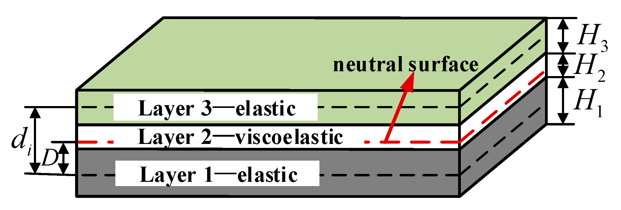
Figure 2.
Three sandwich beams with one identical damping layer.
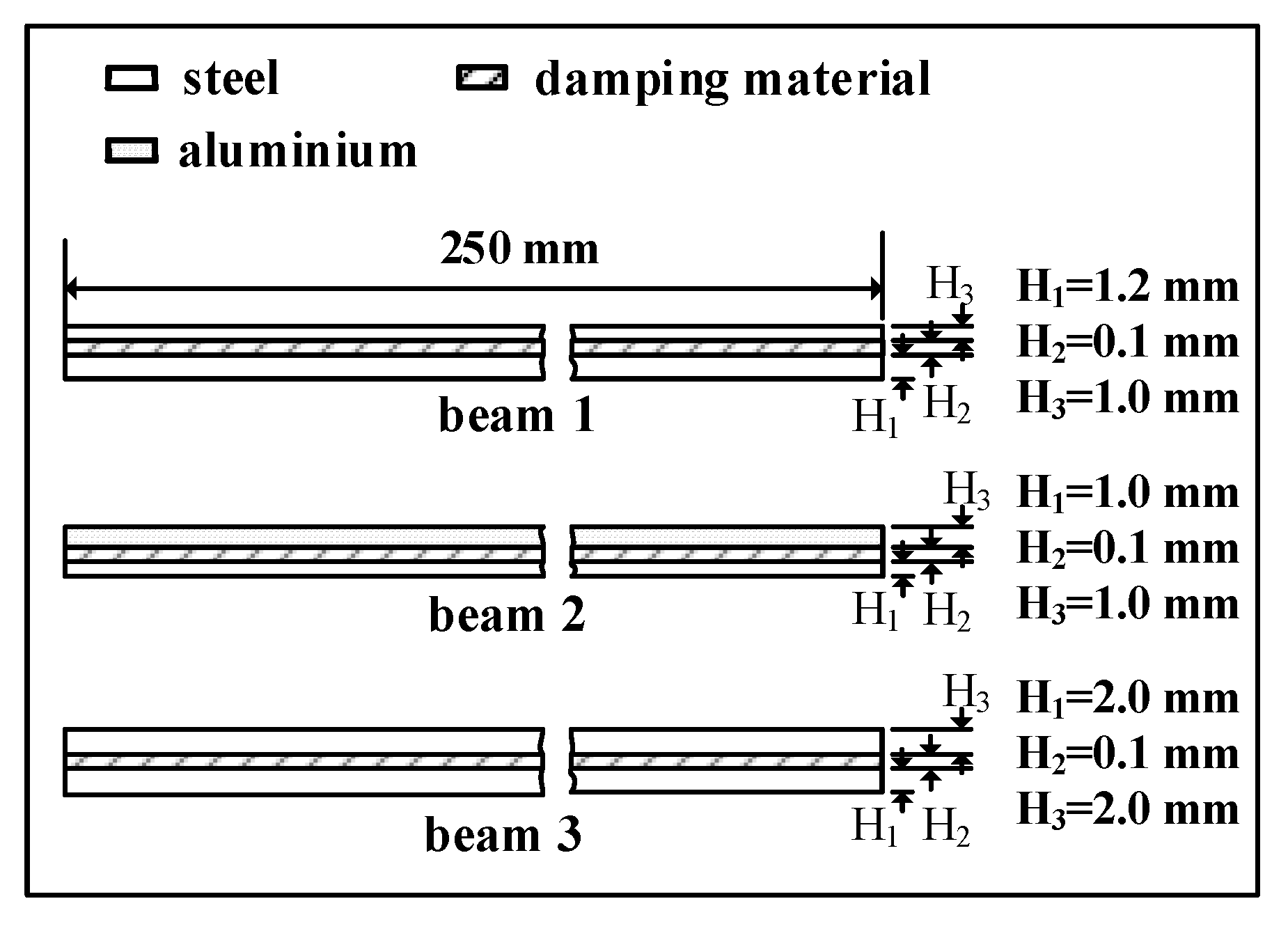
Figure 3.
Simulation results of constant loss factor and shear modulus by three sandwich beams: (a) modal loss factors and (b) modal shear moduli.
Figure 3.
Simulation results of constant loss factor and shear modulus by three sandwich beams: (a) modal loss factors and (b) modal shear moduli.
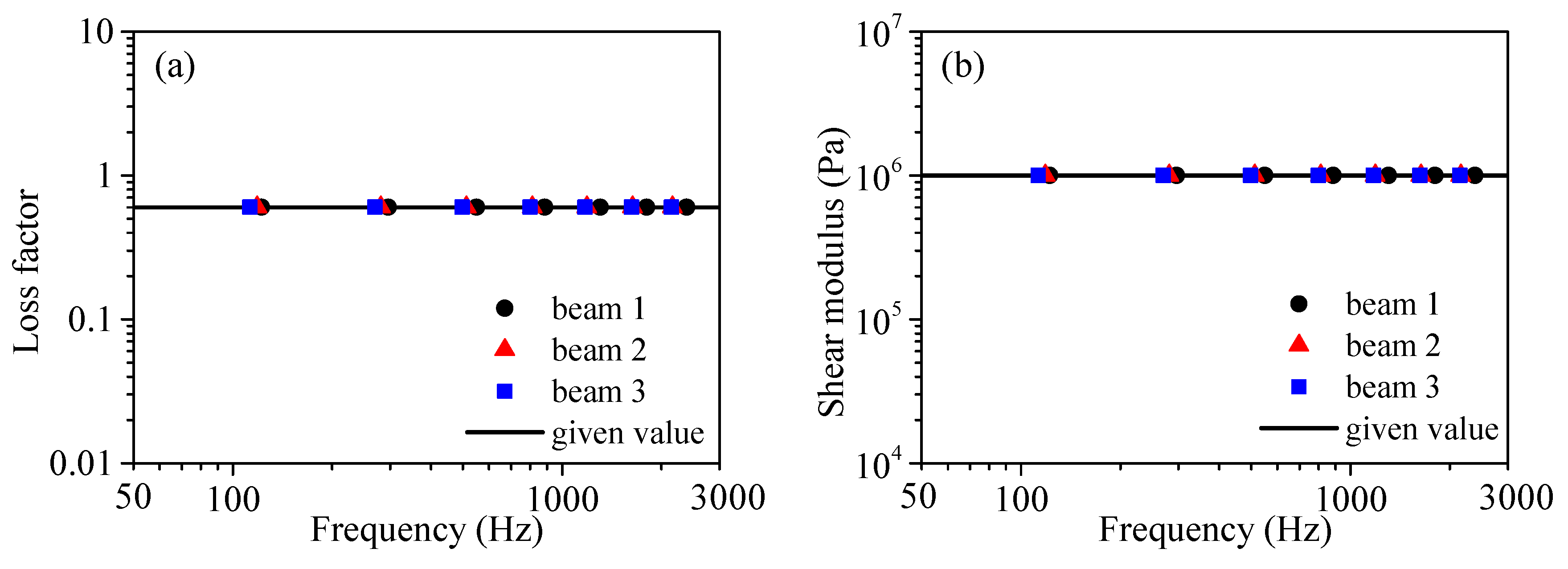
Figure 4.
Simulation results of frequency-dependent loss factor and shear modulus by three sandwich beams: (a) modal loss factors and (b) modal shear moduli.
Figure 4.
Simulation results of frequency-dependent loss factor and shear modulus by three sandwich beams: (a) modal loss factors and (b) modal shear moduli.
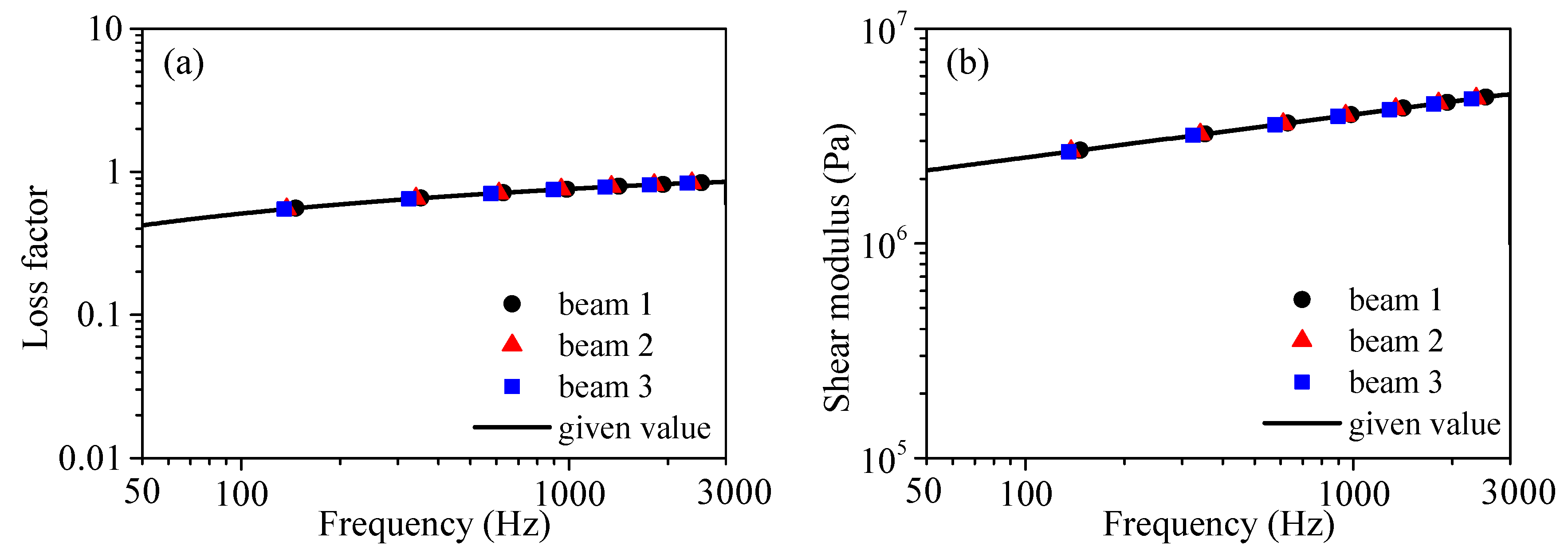
Figure 5.
Schematic diagram of the experimental apparatus.

Figure 6.
Experimental setup.

Figure 7.
Sandwich beam specimens: (a) short asymmetrical specimen H1 ≠ H3, (b) long asymmetrical specimen H1 ≠ H3 and (c) long symmetrical specimen H1 = H3.
Figure 7.
Sandwich beam specimens: (a) short asymmetrical specimen H1 ≠ H3, (b) long asymmetrical specimen H1 ≠ H3 and (c) long symmetrical specimen H1 = H3.
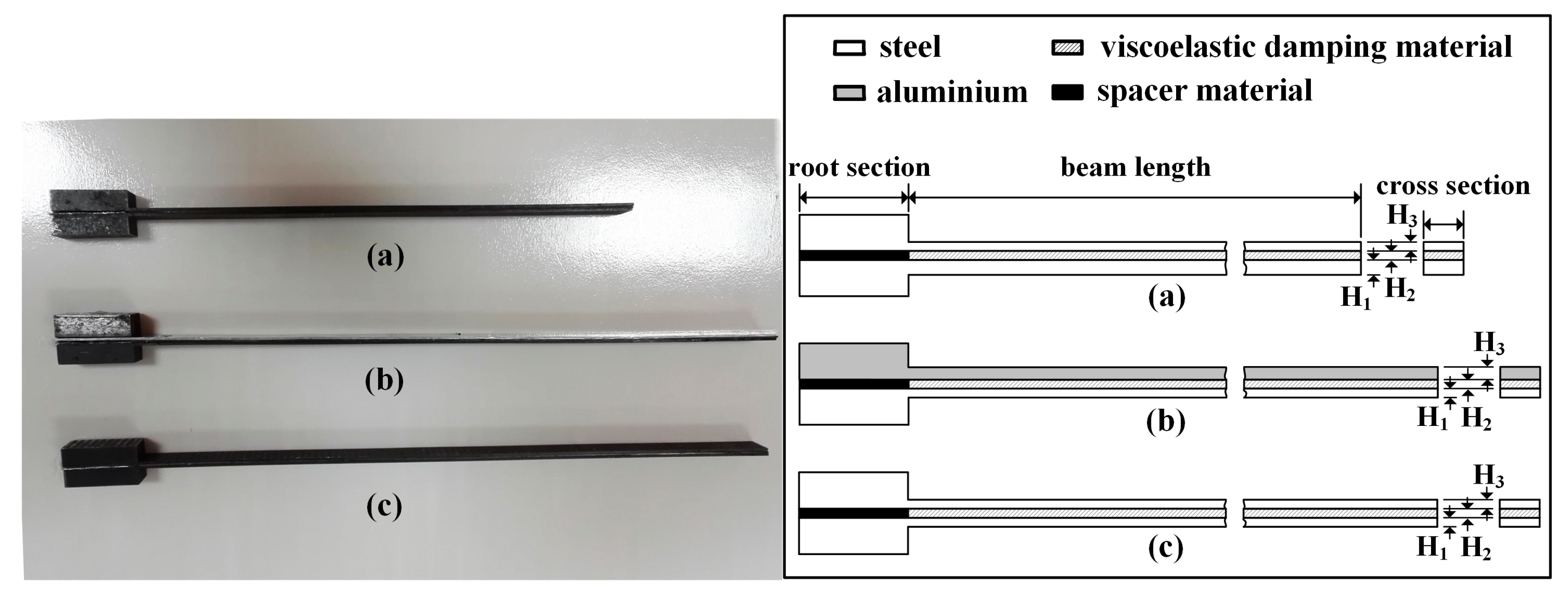
Figure 8.
Normalized frequency responses of sandwich beam specimens: (a) short asymmetrical specimen (b) long asymmetrical specimen and (c) long symmetrical specimen.
Figure 8.
Normalized frequency responses of sandwich beam specimens: (a) short asymmetrical specimen (b) long asymmetrical specimen and (c) long symmetrical specimen.

Figure 9.
Normalized frequency responses of sandwich beam specimens by narrow band excitation: (a) short asymmetrical specimen (b) long asymmetrical specimen and (c) long symmetrical specimen.
Figure 9.
Normalized frequency responses of sandwich beam specimens by narrow band excitation: (a) short asymmetrical specimen (b) long asymmetrical specimen and (c) long symmetrical specimen.

Figure 10.
Test results of structure loss factors of three sandwich beam specimens.

Figure 11.
Test results of modal loss factors by three sandwich beam specimens.
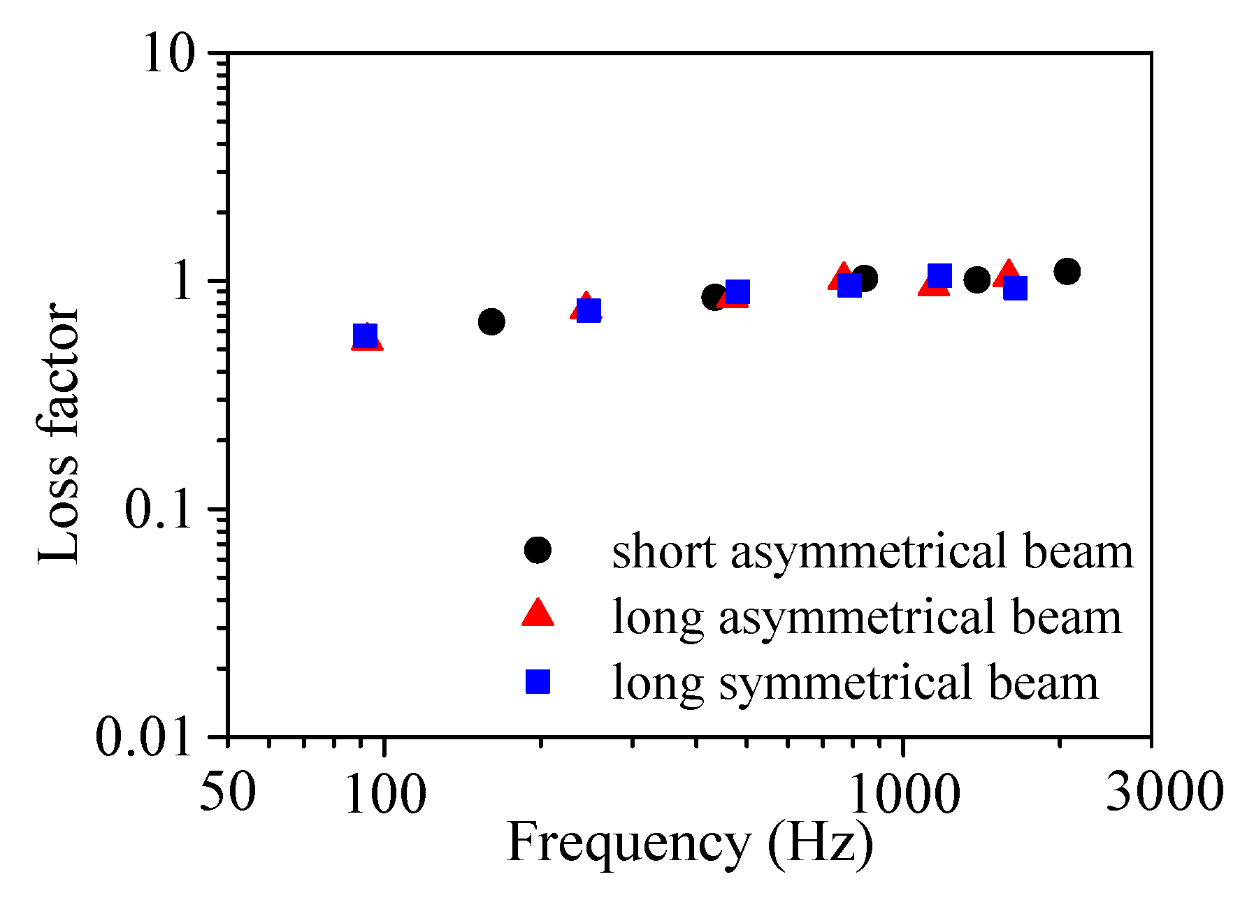
Figure 12.
Test results of modal shear moduli by three sandwich beam specimens.


Table 1.
Tested modal frequencies of the short asymmetrical sandwich beam specimen.
| Beam Type | Materials | Thickness (mm) | Modal Frequency (Hz) | ||||
|---|---|---|---|---|---|---|---|
| 2 | 3 | 4 | 5 | 6 | |||
| Base 1 | Steel | 0.90 | 143.55 | 402.80 | 792.30 | 1311.0 | 1957.0 |
| Base 2 | Steel | 1.02 | 164.50 | 459.50 | 900.30 | 1488.0 | 2221.0 |
| Sandwich | —— | 2.42 | 161.31 | 434.50 | 842.50 | 1388.0 | 2068.0 |
Table 2.
Tested modal frequencies of the long asymmetrical sandwich beam specimen.
| Beam Type | Materials | Thickness (mm) | Modal Frequency (Hz) | |||||
|---|---|---|---|---|---|---|---|---|
| 2 | 3 | 4 | 5 | 6 | 7 | |||
| Base 1 | Steel | 0.97 | 87.63 | 246.06 | 482.80 | 798.50 | 1193.0 | 1668.0 |
| Base 2 | Aluminium | 0.90 | 76.13 | 219.00 | 432.00 | 717.60 | 1078.5 | 1512.0 |
| Sandwich | —— | 2.37 | 92.94 | 245.00 | 469.00 | 768.50 | 1145.0 | 1597.0 |
Table 3.
Tested modal frequencies of the long symmetrical sandwich beam specimen.
| Beam Type | Materials | Thickness (mm) | Modal Frequency (Hz) | |||||
|---|---|---|---|---|---|---|---|---|
| 2 | 3 | 4 | 5 | 6 | 7 | |||
| Base 1 | Steel | 0.97 | 87.63 | 246.30 | 483.00 | 799.50 | 1195.0 | 1669.0 |
| Base 2 | Steel | 0.97 | 87.50 | 246.10 | 483.00 | 798.50 | 1194.0 | 1668.0 |
| Sandwich | —— | 2.44 | 91.94 | 248.00 | 480.75 | 789.25 | 1177.5 | 1645.0 |
© 2018 by the authors. Licensee MDPI, Basel, Switzerland. This article is an open access article distributed under the terms and conditions of the Creative Commons Attribution (CC BY) license (http://creativecommons.org/licenses/by/4.0/).
Share and Cite
MDPI and ACS Style
Wu, Q.; Wang, M. Study on the Dynamic Mechanical Properties of Viscoelastic Materials Based on Asymmetrical Sandwich Beams. Appl. Sci. 2018, 8, 1359. https://doi.org/10.3390/app8081359
AMA Style
Wu Q, Wang M. Study on the Dynamic Mechanical Properties of Viscoelastic Materials Based on Asymmetrical Sandwich Beams. Applied Sciences. 2018; 8(8):1359. https://doi.org/10.3390/app8081359
Chicago/Turabian StyleWu, Qingqing, and Minqing Wang. 2018. "Study on the Dynamic Mechanical Properties of Viscoelastic Materials Based on Asymmetrical Sandwich Beams" Applied Sciences 8, no. 8: 1359. https://doi.org/10.3390/app8081359
Note that from the first issue of 2016, this journal uses article numbers instead of page numbers. See further details here.