Improving Stability Prediction in Peripheral Milling of Al7075T6


1
Tecnológico de Monterrey, Escuela de Ingeniería y Ciencias, Av. Eugenio Garza Sada 2501, Monterrey, Nuevo León 64849, Mexico
2
Department of Mechanical Engineering, University of the Basque Country, Alameda de Urquijo s/n, 48013 Bilbao, Bizkaia, Spain
*
Author to whom correspondence should be addressed.
Appl. Sci. 2018, 8(8), 1316; https://doi.org/10.3390/app8081316
Submission received: 11 July 2018
/
Revised: 1 August 2018
/
Accepted: 1 August 2018
/
Published: 7 August 2018
(This article belongs to the Special Issue Mechanical Behaviour of Aluminium Alloys)
Abstract
:Chatter is an old enemy to machinists but, even today, is far from being defeated. Current requirements around aerospace components call for stronger and thinner workpieces which are more prone to vibrations. This study presents the stability analysis for a single degree of freedom down-milling operation in a thin-walled workpiece. The stability charts were computed by means of the enhanced multistage homotopy perturbation (EMHP) method, which includes the helix angle but also, most importantly, the runout and cutting speed effects. Our experimental validation shows the importance of this kind of analysis through a comparison with a common analysis without them, especially when machining aluminum alloys. The proposed analysis demands more computation time, since it includes the calculation of cutting forces for each combination of axial depth of cut and spindle speed. This EMHP algorithm is compared with the semi-discretization, Chebyshev collocation, and full-discretization methods in terms of convergence and computation efficiency, and ultimately proves to be the most efficient method among the ones studied.
1. Introduction
Chatter is a dynamic instability phenomenon that diminishes the quality of parts and tool performance. It is an old adversary for machinists, and one of the most common issues in manufacturing. However, nowadays, due to the rapid growth of global competition to reduce cost and the increased dimensional accuracy in monolithic and thin geometries demanded by aeronautical industries, research has been focused on more accurate predictive models and methods for optimizing metal removal rates without chatter. Those models are delay-differential equations (DDE) with infinite dimensional state space. Particularly in milling, the equation of motiving is a DDE with a time-periodic coefficient, transformed in a finite dimensional system. According to the Floquet theory, the stability properties are determined by the system’s monodromic operator.
The literature provides various approaches for predicting stability lobes in various machining operations as a function of spindle speed and chip load. For instance, Smith and Tlusty et al. [1] presented a method for generating the stability lobes in milling operations by using time-domain numerical simulations. Altintas and Budak [2] developed the first analytical solution that led to the milling operation prediction of stability lobes in the frequency domain by averaging the time-dependent periodic directional coefficients. This method provides accurate stability predictions. except for where there are cutting operations at low radial immersion. Davies et al. [3] proved that the traditional regenerative stability theory could not accurately predict stability lobes at low radial immersions. However, Merdol and Altintas [4] proved that the multi-frequency approach [5] was able to accurately predict low radial immersion milling stability lobes if the harmonics of the tooth-passing frequencies were included in the eigenvalue solution. The double-period bifurcation at small radial immersion was investigated by Bayly et al. [6] by applying the time finite element analysis (TFEA) in the solution of the governing equations of motion. The approximate solution obtained from this method was cast in the form of a discrete map that related position and velocity at the beginning and end of each element. Then, the eigenvalues of the discrete map were used to determine the stability bounds. Another method that forms a finite dimensional transition matrix as an approximation of the infinite dimensional monodromic operator is the semi-discretization (SD) method. In this method, first introduced by Insperger and Stepan [7], the delayed terms are discretized, the undelayed terms unchanged, and the time-periodic coefficients approximated by piecewise constant functions. An updated version of the SD method for periodic systems with a single discrete time delay was proposed by Insperger and Stepan [8]. In this approach, the time step is chosen as an integer fraction of the time period, meaning that the Floquet transition matrix is determined over a single period. Insperger et al. showed that the second and higher-order approximations of the delayed term did not provide better convergence than the first-order one [9,10]. On the other hand, Butcher et al. [11] developed a new approximation technique for studying the stability properties of milling operations. This approach was based on the properties of Chebyshev polynomials and used a collocation representation of the solution at their endpoints. The stability bounds of the corresponding equations were determined by the eigenvalues of the approximate monodromic matrix, mapping function values at the collocation points from one interval to the next. They concluded that the Chebyshev collocation (CH) approach provided results similar to other methods which used equispaced points. This approach was extended by the authors in complex turning applications [12,13] and compared to other computation techniques [14].
Ding et al. [15] developed a full-discretization (FD) method based on the direct integration scheme for prediction of milling stability lobes by taking the regenerative effect into account in the state-space which is represented in integral form. They claimed that this method had better computational efficiency than the SD method developed by Insperger and Stepan [8]. However, Insperger [16] showed that the full-discretization and SD methods were similar, as both methods approximated the delay-differential equations by using a series of ordinary differential equations, meaning that the FD method was an alternative to the SD method with only a slightly different concept in the discretization scheme.
Recently, Ding et al. [17] proposed a second-order full-discretization method to determine the stability lobes of milling operations. After the time period was equally discretized into a finite set of intervals, the full-discretization method was developed to handle the integration term of the system. They showed the practicality of the second-order full-discretization method, in terms of both accuracy and computational time efficiency. The authors [18] adapted the homotopy theory to predict stability lobes by proposing an initial solution and then deforming it to accurately approximate the monodromic operator by EMHP method. Since there are various approaches in literature to predict stability properties of DDEs, it is important to investigate the capabilities of each method in terms of convergence and computation time over a more complicated modeling of forces in the milling process.
2. Materials and Methods
2.1. Milling Stability Prediction with the EMHP Method
In order to predict stability in machining operations, in this paper we focus on the manufacturing of a thin-walled workpiece through peripheral milling operations. The workpiece has a single degree of freedom (flexibility only in the y-direction according to the machine tool standard axis nomenclature), with a dynamic model of the following form:
Here, mm represents the modal mass, ζ is the damping ratio, ωn is the natural angular frequency, and Fy is the cutting force over the workpiece in the y-direction, which is given by:
where zn is the number of teeth, Ktc and Krc are the tangential and the normal cutting force coefficients, and φj (t) is defined as:
where n is the spindle speed in rpm. The function g(φj(t)) is a screen function, and is equal to 1 if the tooth j is in the cut, and is equal to 0 if j is out of the cut. To obtain the stability lobes of Equation (1), we proposed a solution procedure based on the EMHP algorithm [18], which relies on a sequence of subintervals that provide approximate solutions requiring less CPU time in comparison with other methods found in the literature. In this methodology, we rewrote Equation (1) as:
where Fyt = Fy(t), and yi(T) denotes the approximate solution of order m in the i-th sub-interval that satisfies the initial conditions , . The Equation (1) can be written in state space, in accordance with the following matrix-form representation:
where , A(t − τ) = A(t), B(t − τ) = B(t), and τ is the time delay. By following the homotopic procedure, the equivalent form of Equation (5) can be written as:
where xi(T) denotes the m order solution of Equation (6) in the i-th sub-interval that satisfies the initial conditions , At, and Bt represents the values of the periodic coefficients at the time t. In order to approximate the delay term in Equation (6), the period [t0 − t0] is discretized into N equally-spaced points, but the method does not accept strictly-spaced sub-intervals. Thus, each sub-interval has a time span equal to Δt = τ/(N − 1). Here, we assumed that the function in the delay sub-interval [ti−N, ti−N+1] had a first-order polynomial representation, of the form:
To simplify the notation, we let xi ≡ xi(Ti). Equation (7) was then introduced into Equation (6), to get:
where:
By following our homotopic procedure, we assumed the homotopic representation of Equation (8) was of the form:
To obtain the stability lobes of Equation (1), the solution of Equation (10) was rewritten in the form:
where:
The approximate solution given by Equation (12) can be written as a discrete map by using the following identity:
where Di is a coefficient matrix, wi−1 is a vector of the form:
By using Equations (11) and (12), we could easily construct the coefficient matrix Di [8]. We then determined the transition matrix Φ over the period τ = (N − 1)Δt by coupling each approximate solution through the discrete map Di, i = 1, 2, …, (N − 1), to get:
Then, the stability lobes of Equation (1) were determined by computing the eigenvalues of the transition matrix given by Equation (15).
2.2. Effect of Runout and Cutting Speed
In this section, the effects of runout and cutting speed in the peripheral milling of Al7075T6 alloy at high cutting speeds are investigated—or more specifically, their influence in the prediction and accuracy of stability lobes is analyzed.
Because perfect cutting is impossible, runout appears naturally in every milling operation and unfortunately produces undesirable effects, such as uneven material removal, wear, and poor surface quality. It is defined as an offset of the tool’s geometrical axis with respect to the spindle rotation axis, as shown in Figure 1. This is impossible to avoid because the total runout is a sum of the misalignments of the spindle, tool-holder, and milling tool itself. This makes difficult to predict the current flutes’ trajectories, as the real cheap thickness is defined by the trajectory at every point in each flute, which changes not only in the x-y plane but also in space.
When considering this effect during milling operations, the cutting force can be expressed as:
where ρj represents a weighted factor that is related to the cutting force magnitudes for each flute, j. Here, we propose a different alternative to consider the runout effects, by assuming that relating ρj is given as:
where represents the tool’s apparent runout radius in the feed direction, α is the runout angle, and fz is the feed rate. Notice that δ represents the chip variation in the feed direction (x-axis). To determine the value of experimentally, once the milling tool is attached to in the machine center, a deflection gauge fixed to the table was set to zero once the first flute pushed the gauge. Then, the apparent radius was estimated by the average deflection between 180°-spaced flutes. The proportional factor ρj for the chip load in the actual j teeth was then calculated as the nominal feed rate plus the ratio /fz, representing the percentage of the nominal feed rate.
Note that the factor is related to the amount of cutting force magnitude of each tooth that depends on the apparent runout radius. In the ideal case of no runout, i.e., δ = 0 and ρj = 1, Equation (15) becomes periodic in τ. On the other hand, when the runout influences the machining processes, the periodic behavior arises, related to the spindle period τT.
When the runout is zero, the dynamical system exhibits only quasi-periodic (Hopf bifurcation) and flip-bifurcation behaviors of period two, while chatter in period one never arises. In multi-flute machining processes, the runout practically always arises since the tool is not perfectly symmetric. In this case, the principal period is equal to the spindle rotation period τT = 60/n. Thus, the determination of the stability lobes by the EMHP method can be done by computing the transition matrix Φ over the spindle rotation period, i.e., by considering that Equation (15) can be written as:
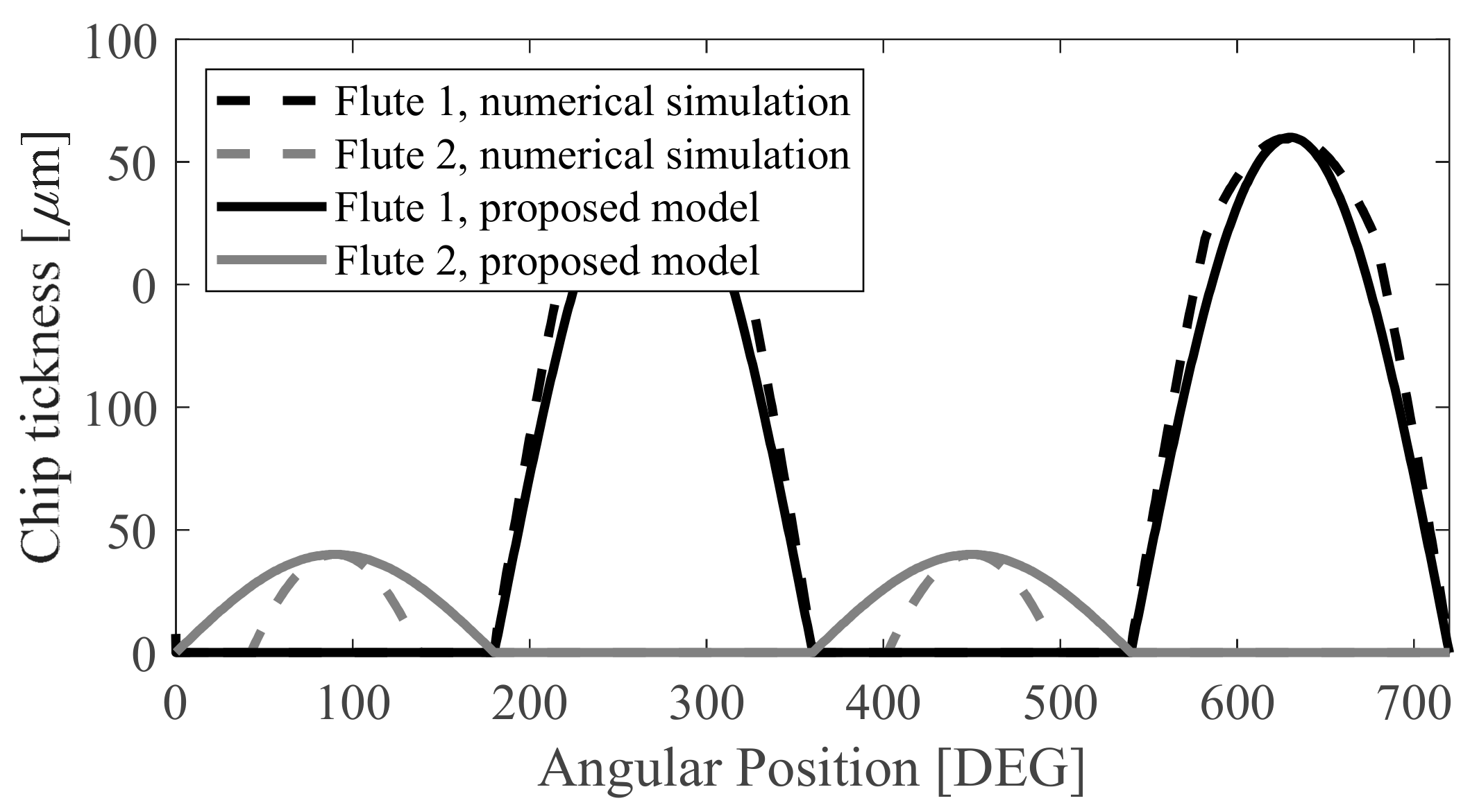
Within this study, a 2-fluted, 16 mm-diameter, carbide end-mill (30° helix) was used for the experiments. The apparent runout was measured by means of a digital gauge, and the apparent radius was estimated to be at 17 μm. In order to validate the proposed runout model, this was compared with the chip thickness in the time domain by a time domain simulation similar to that developed in [19]. The results of this are shown in Figure 2. Note that the model matches the maximum thickness in every single flute, but it does not capture the discontinuity when one of the flutes is not cutting. In spite of this, the analytical model is a good approximation for the stability analysis.
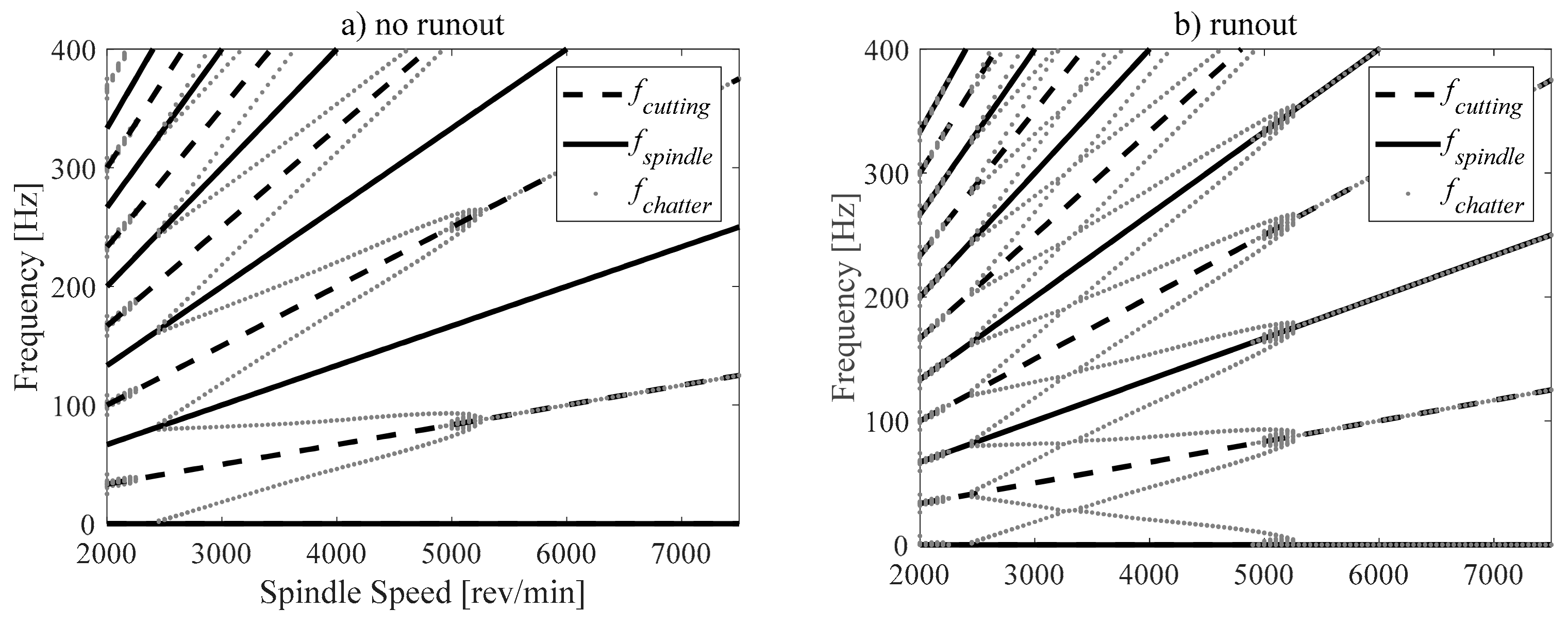
When considering runout effects, new chatter frequencies appeared due to the one-period bifurcation, which was many times the spindle rotation frequency of a two-flute end mill (see Figure 3). The plotted chatter frequencies were also used when comparing with experimental chatter frequencies for validation later on.
With regard to cutting speed, it is commonly assumed in the literature that the stability analysis and mechanistic force models are independent of this parameter [20,21]. However, during the machining of aluminum workpieces, cutting speed has a strong influence on the magnitude of the cutting forces and on the stabilities’ boundaries. According to Asthakov [22], cutting speed affects the chip formation process in two major ways. Firstly, it changes the strain rate in the deformation zone, which influences the resistance of the workpiece material and the thermal energy generated during its deformation processes. Secondly, the cutting speed influences the tool-chip’s relative speed and the natural length of the tool-chip interface.
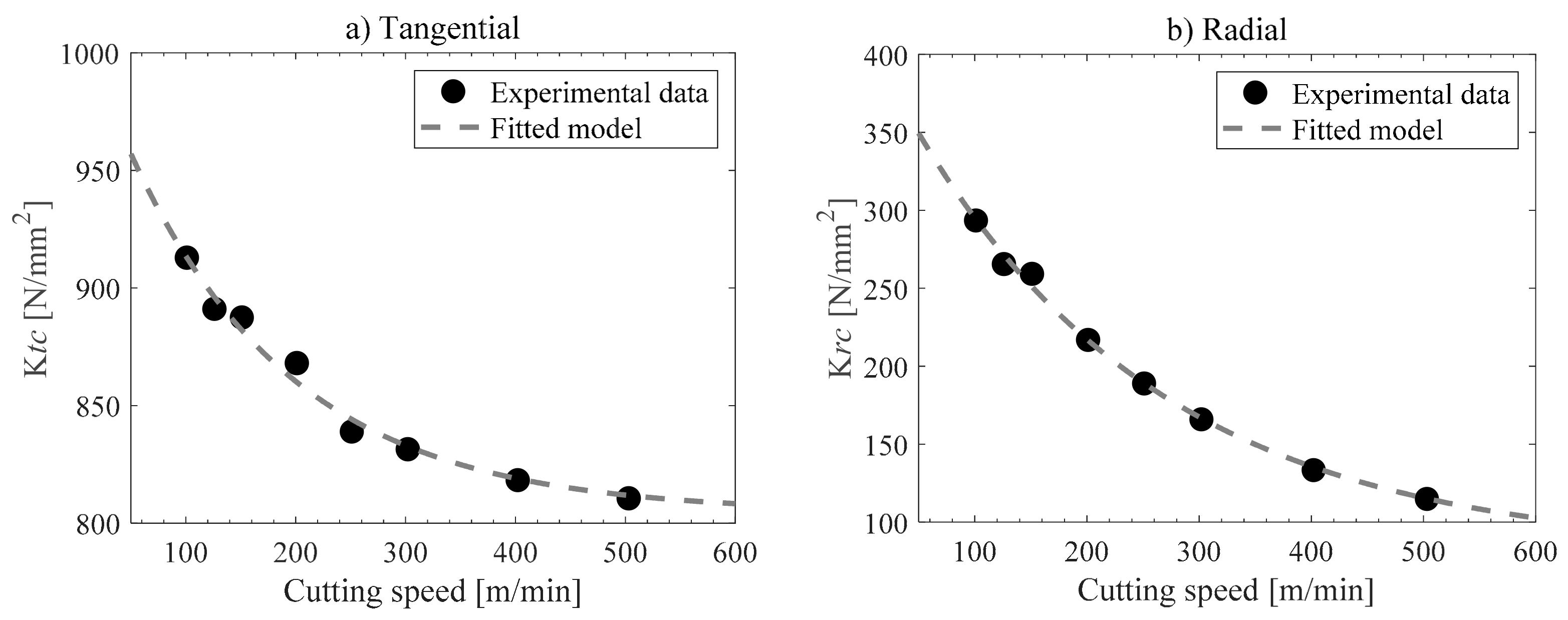
Therefore, a proper characterization should consider variable cutting coefficients. In this work, cutting coefficients in the tangential and normal directions were obtained as functions of the cutting speed. Up to 120 full-immersion cutting tests were done by using tools with 1 mm–4 mm depth of cut, 5 feed rates (0.05–0.25 mm), and 6 cutting velocities (2000–10,000 rpm), as shown in Figure 4. These tests were performed on a Kistler dynamometer (9255 B). The solid end-mill was a 30° helix, which was 16 mm in diameter with two flutes, and the material workpiece selected was aluminum 7075-T6. It is important to mention that the associated spindle speed was not greater than 1/5 of the natural frequency of the chain table dynamometer workpiece (≈1.6 KHz) in order to obtain reliable measurements [23].
During the interpretation of the experimental data, shear cutting coefficients showed significant variations due to the cutting speed in the radial and tangential directions. However, the fact that friction effects contributed to the total magnitude of the cutting forces due to cutting speed is negligible. We used a simple exponential model to fit the experimental data:
where the parameters for the fitting are Aq, Bq, and αq are obtained for the tangential and normal directions, as: At = 53.3, Bt = 201, αt = 0.0067, Ar = 84.4, Bt = 20, and αt = 0.0045.
3. Results
3.1. Experimental Validation of Stability Prediction
In order to validate the proposed approach, down-milling tests were conducted in a conventional milling center. A monolithic artifact of Al7075T6 was designed to reproduce the dynamic response of a single degree of freedom system in the y-axis, which is orthogonal to the feedrate direction. The workpiece displacements were recorded and analyzed via Fast Fourier Transform, to observe the frequency content and to compare it with tool cutting frequencies (see Figure 3).
The modal parameter values of the end-milling cutting processes were found by impact testing: ωn = 499 rad/s, ξ = 0.04, and mm = 10.1 kg. The transfer function obtained through the impact test fit well with the theoretical results. By using these values and computing the eigenvalues of the transition matrix, the stability lobes of the end-milling cutting operation were calculated. Figure 5 shows the stability charts for down-milling with 25% radial immersion, feed rate 0.05 mm/teeth, and a measured apparent radius of 17 µm. The discontinued lines correspond to the typical stability lobes when the cutting speed, runout, and helix angle are neglected, while the solid lines plot the stability boundaries, taking these effects into account.
The stable cutting data are denoted by circles, unstable quasi-periodic by square symbols, and unstable double periodic by diamonds. Down triangles denote one period chatter respectively, and up triangles denote quasi-one-period data. When it was difficult to distinguish between experiments with stable and unstable data due to there not being a dominant frequency, the vibration amplitude was considered as a second criterion. The experimental data demonstrated the high accuracy of the stability boundary prediction, even to predict the transition between quasi-periodic and double-periodic unstable zones. For comparison, the effects of the runout and cutting speed were also introduced in the CH, SD, FD methods. In this case, the boundary limits obtained were almost identical when N = 30, however, the convergence rate and computation times differed depending on the method.
3.2. Accuracy and Computation Times
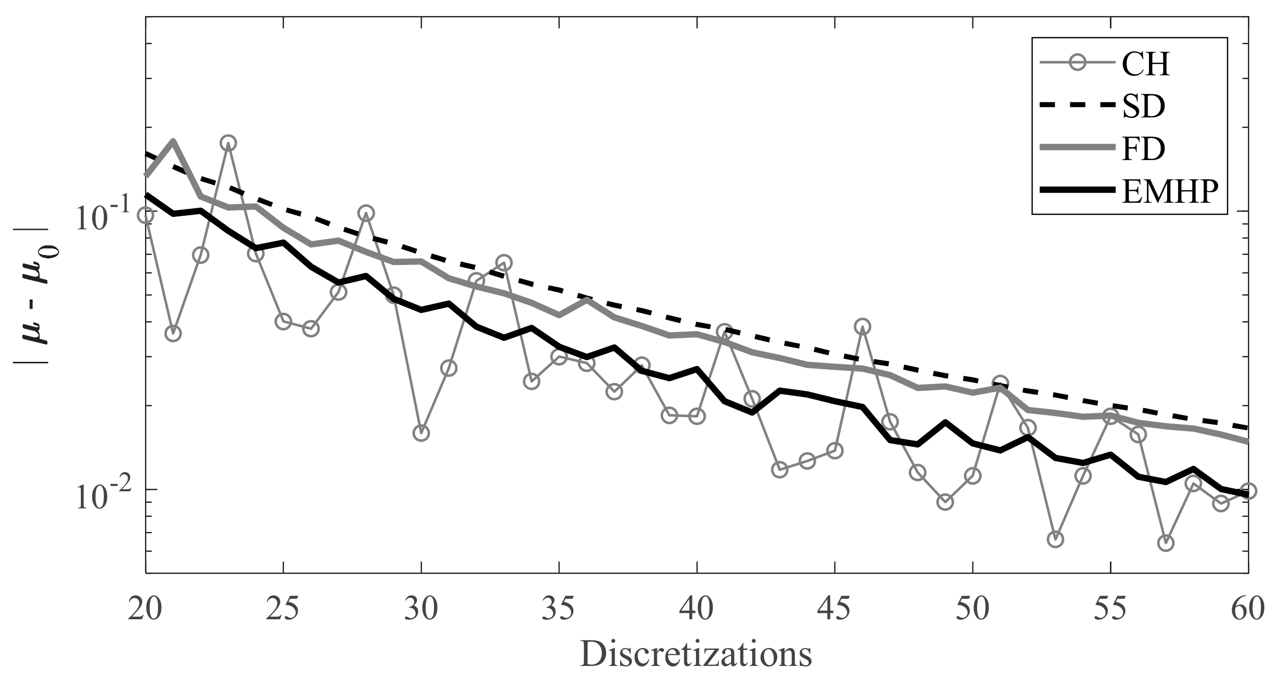
Since the convergence of the eigenvalues depends on parametric values (n, ap), a more general approach has been studied using an 11 × 11 matrix containing an equally-spaced sweep of spindle speeds (2000 rpm to 7500 rpm) and axial depths of cut (0 to 10 mm). The difference between the matrix’s approximate critical eigenvalues µ and exact ones µ0 is presented as the function of the number of discretizations, or subintervals. The exact matrix of the eigenvalues µ0 was determined by each corresponding method with N = 200. Figure 6 shows the results for 25% radial immersion. Note that this figure does not compare the converged values between methods, as no method converges at the same eigenvalues.
Another important parameter is the time it takes to compute the stability lobes. Here, the average time needed to compute an eigenvalue for a combination of parameters (n, ap) is used, which was calculated over the 11 × 11 matrix used previously. Figure 7 shows the average time for each method as a function of the number of discretization or sub-intervals. Once again, it is clear that the fastest methods for the stability performed were the CH and EMHP methods. It is important to note that the immersion does not change the number of mathematical operations. Figure 7 is valid for any value of radial immersion.
4. Discussion
Chatter is an old enemy to manufacturers but still strongly affects machining times and workpiece quality. Together with mathematical models, this work proposed a numerical method to reproduce many effects arising in practice, which need to be introduced for an accurate representation of the system’s stability. These parameters are common ones, such as the geometry of the end-mill (tool diameter, flutes, helix angle, etc.), but also many others, such as (1) runout, (2) cutting speed, and (3) helix angle.
Particularly in the machining of the aluminum alloy family, the authors found that it is mandatory to incorporate the effects of cutting speed in the calculation of the stability lobes, as these may differ greatly depending on the constant or variable cutting coefficients.
The helix angle did not have an important influence in this chart as the helix pitch is 43.5 mm, higher than the 10 mm limit plotted. However, the runout effect is significant not only in the chatter frequencies but also over the modulus of the multipliers. Notice that these values have been increased towards the stability boundaries, and a new region, or flip lobe (when the multipliers leave the unit circle for the real negative axis) appears in the middle of the Hopf bifurcation at around 3250 rpm. As runouts always appear in the workshop, this proposed model can be easily incorporated into any cutting force model because it is based on an experimental measurement.
The cutting speed has a more predictable influence, since the cutting coefficients decrease while the cutting speed increases, and stability boundaries grow as the spindle speed increases. For instance, at 7500 rpm, the axial depth of the cut limit was predicted to be 5.6 mm using a typical analysis, but increased to 7.8 mm for the improved analysis.
The boundary limits are especially sensitive in the stable zones between consecutive lobes, which are often used to improve chip removal rates. For instance, when the spindle speed was 2500 rpm in Figure 5, the prediction here failed due to the severe transition between stable and unstable behavior (see slope of the diagram).
If the prediction model is to be put to good use, a convenient characterization should be done. This non-trivial aspect was not studied by the scientific literature. Models usually assume cutting coefficients to be constant by characterizing and validating the tool-material pair at the same cutting speeds. However, this is not realistic because the most interesting zones between lobes will vary depending on the system’s dynamics. The resulting change in the cutting coefficient due to cutting speed cannot be neglected when milling aluminum alloys.
The EMHP method was compared with other similar and competitive methods in the literature, such as the Chebyshev collocation, semi-discretization, and full-discretization methods. A single degree of freedom model was developed and validated with the mentioned updates. When considering computation time and convergence rate, the EMHP and Chebyshev collocation methods proved to be the most efficient when N < 60. In terms of overall accuracy, all four methods resulted in the same stability lobes when N > 30, but this may not necessarily be the case for other milling conditions.
5. Conclusions
In this work, we studied how we could realistically deal with stability problems when machining aluminum alloys at different cutting speeds. A 1 degree-of-freedom model was solved by using the homotopic perturbation technique. In this case, the proposed cutting force model considered various cutting coefficients, including runout. Stability lobes with varying cutting coefficients and spindle speeds were calculated and experimentally verified for the first time. The developed method proved to be an efficient technique with respect to other state-of-the-art methods. The main contributions can be summarized as:
- We observed a significant variation in the cutting forces depending on cutting speeds, and a model was thus proposed where the cutting-force coefficients varied depending on the cutting speed. Using an exponential cutting speed model, we described how the cutting-force coefficient decreased as a function of the increase in cutting speed.
- It was experimentally demonstrated that inclusion of the effects of the helix angle, runout, and characterization dependent on the cutting speed allowed for much more precise stability boundaries. Furthermore, typical stability lobes with constant cutting coefficients were found to only be valid for a narrow spindle speed range, meaning that their applicability is not valid in real practice.
- The convergence of the EMHP was compared with other efficient methods, such as the semi-discretization and full-discretization methods. When considering numeric convergence and computation times, the EMHP and Chebyshev proved to be the most efficient methods.
Author Contributions
Conceptualization, methodology, software and writing, D.O. and G.U.; Resources and supervision, A.E.-Z. and L.N.L.d.L.
Funding
The authors wish to acknowledge the financial support received from HAZITEK program, from the Department of Economic Development and Infrastructures of the Basque Government and from FEDER funds. Additional support was provided by the Tecnológico de Monterrey, through the Research Group in Nanomaterials and Devices Design.
Conflicts of Interest
The authors declare no conflict of interest. The founding sponsors had no role in the design of the study; in the collection, analyses, or interpretation of data; in the writing of the manuscript, and in the decision to publish the results.
References
- Smith, S.; Tlusty, J. Efficient Simulation Programs for Chatter in Milling. CIRP Ann. 1993, 42, 463–466. [Google Scholar] [CrossRef]
- Altintas, Y.; Budak, E. Analytical Prediction of Stability Lobes in Milling. CIRP Ann. 1995, 44, 357–362. [Google Scholar] [CrossRef]
- Davies, M.A.; Pratt, J.R.; Dutterer, B.; Burns, T.J. Stability prediction for low radial immersion milling. J. Manuf. Sci. Eng. 2002, 124, 217–225. [Google Scholar] [CrossRef]
- Merdol, S.D.; Altintas, Y. Multifrequency solution of chatter stability for low immersion milling. J. Manuf. Sci. Eng. 2004, 126, 459–466. [Google Scholar] [CrossRef]
- Budak, E.; Altintas, Y. Analytical prediction of chatter stability in milling—Part 1: General formulation. J. Dyn. Syst. Meas. Control 1998, 120, 22–30. [Google Scholar] [CrossRef]
- Bayly, P.V.; Halley, J.E.; Mann, B.P.; Davies, M.A. Stability of interrupted cutting by temporal finite element analysis. J. Manuf. Sci. Eng. 2003, 125, 220–225. [Google Scholar] [CrossRef]
- Insperger, T.; Stepan, G. Semi-discretization method for delayed systems. Int. J. Numer. Methods Eng. 2002, 55, 503–518. [Google Scholar] [CrossRef]
- Insperger, T.; Stepan, G. Updated semi-discretization method for periodic delay-differential equations with discrete delay. Int. J. Numer. Methods Eng. 2004, 61, 117–141. [Google Scholar] [CrossRef]
- Insperger, T.; Stepan, G.; Turi, J. Comparison of zeroth-and first-order semi-discretizations, for the delayed Mathieu equation. In Proceedings of the 43rd IEEE Conference on Decision and Control, Nassau, Bahamas, 14–17 December 2004; Volume 3, pp. 2625–2629. [Google Scholar]
- Insperger, T.; Stepan, G.; Turi, J. On the higher-order semi-discretizations for periodic delayed systems. J. Sound Vib. 2008, 313, 334–341. [Google Scholar] [CrossRef]
- Butcher, E.A.; Nindujarla, P.; Bueler, E. Stability of up-and down-milling using Chebyshev collocation method. In Proceedings of the ASME International Design Engineering Technical Conferences and Computers and Information in Engineering Conference, Long Beach, CA, USA, 24–28 September 2005; Volume 6, pp. 841–850. [Google Scholar]
- Urbikain, G.; López de Lacalle, L.N.; Fernández, A. Regenerative vibration avoidance due to tool tangential dynamics in interrupted turning operations. J. Sound Vib. 2014, 333, 3996–4006. [Google Scholar] [CrossRef]
- Urbikain, G.; Olvera, D.; López de Lacalle, L.N.; Elías-Zúñiga, A. Spindle speed variation technique in turning operations: Modeling and real implementation. J. Sound Vib. 2016, 383, 384–396. [Google Scholar] [CrossRef]
- Urbikain, G.; Olvera, D.; López de Lacalle, L.N.; Elías-Zúñiga, A. Stability and vibrational behaviour in turning processes with low rotational speeds. Int. J. Adv. Manuf. Technol. 2015, 80, 871–885. [Google Scholar] [CrossRef]
- Ding, Y.; Zhu, L.; Zhang, X.; Ding, H. A full-discretization method for prediction of milling stability. Int. J. Mach. Tools Manuf. 2010, 50, 502–509. [Google Scholar] [CrossRef]
- Insperger, T. Full-discretization and semi-discretization for milling stability prediction: Some comments. Int. J. Mach. Tools Manuf. 2010, 50, 658–662. [Google Scholar] [CrossRef]
- Ding, Y.; Zhu, L.; Zhang, X.; Ding, H. Second-order full-discretization method for milling stability prediction. Int. J. Mach. Tools Manuf. 2010, 50, 926–932. [Google Scholar] [CrossRef]
- Compeán, F.I.; Olvera, D.; Campa, F.J.; López de Lacalle, L.N.; Elías-Zúñiga, A.; Rodríguez, C.A. Characterization and stability analysis of a multivariable milling tool by the enhanced multistage homotopy perturbation method. Int. J. Mach. Tools Manuf. 2012, 57, 27–33. [Google Scholar] [CrossRef]
- Schmitz, T.L.; Couey, J.; Marsh, E.; Mauntler, N.; Hughes, D. Runout effects in milling: Surface finish, surface location error, and stability. Int. J. Mach. Tools Manuf. 2007, 47, 841–851. [Google Scholar] [CrossRef]
- Engin, S.; Altintas, Y. Mechanics and dynamics of general milling cutters. Part I: Helical end mills. Int. J. Mach. Tools Manuf. 2001, 41, 2195–2212. [Google Scholar] [CrossRef]
- Mann, B.P.; Insperger, T.; Bayly, P.V.; Stepan, G. Stability of up-milling and down-milling, part 2: Experimental verification. Int. J. Mach. Tools Manuf. 2003, 43, 35–40. [Google Scholar] [CrossRef]
- Astakhov, V.P. Tribology of Metal Cutting, 1st ed.; Elsevier Science: New York, NY, USA, 2006; Volume 52. [Google Scholar]
- Kumme, R.; Mack, O.; Bill, B.; Gossweiler, C.; Haab, H.R. Dynamic Properties and Investigations of Piezoelectric Force Measuring Devices. VDI BERICHTE 2002, 1685, 161–172. [Google Scholar]
Figure 1.
(Left) geometrical runout; (Right) approximated runout.
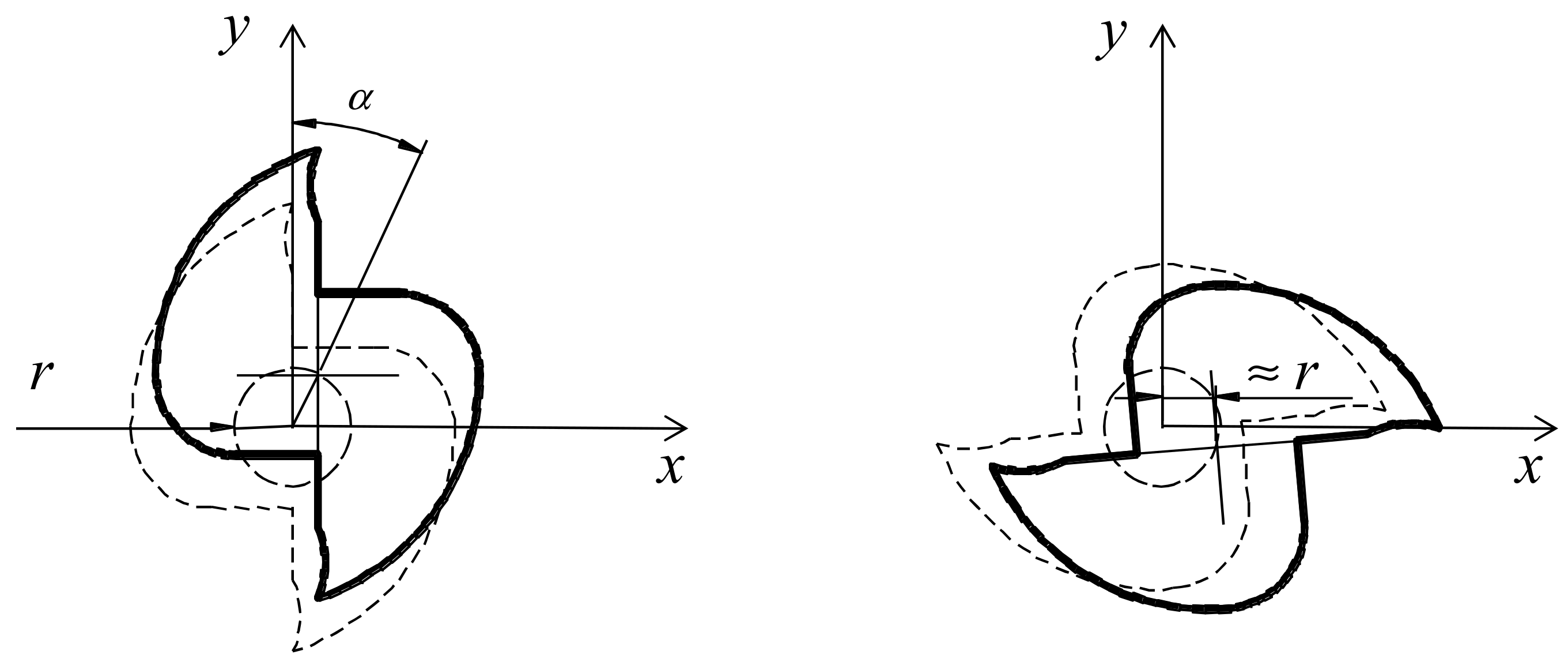
Figure 2.
Proposed runout model versus a time domain simulation runout.

Figure 3.
Chatter frequencies, (a) no runout, and (b) runout.

Figure 4.
Experimental and fitted curves of cutting shear coefficients in the (a) tangential and (b) radial directions.
Figure 4.
Experimental and fitted curves of cutting shear coefficients in the (a) tangential and (b) radial directions.

Figure 5.
Experimental data from the down-milling operation, comparison between typical and improved stability analysis.
Figure 5.
Experimental data from the down-milling operation, comparison between typical and improved stability analysis.
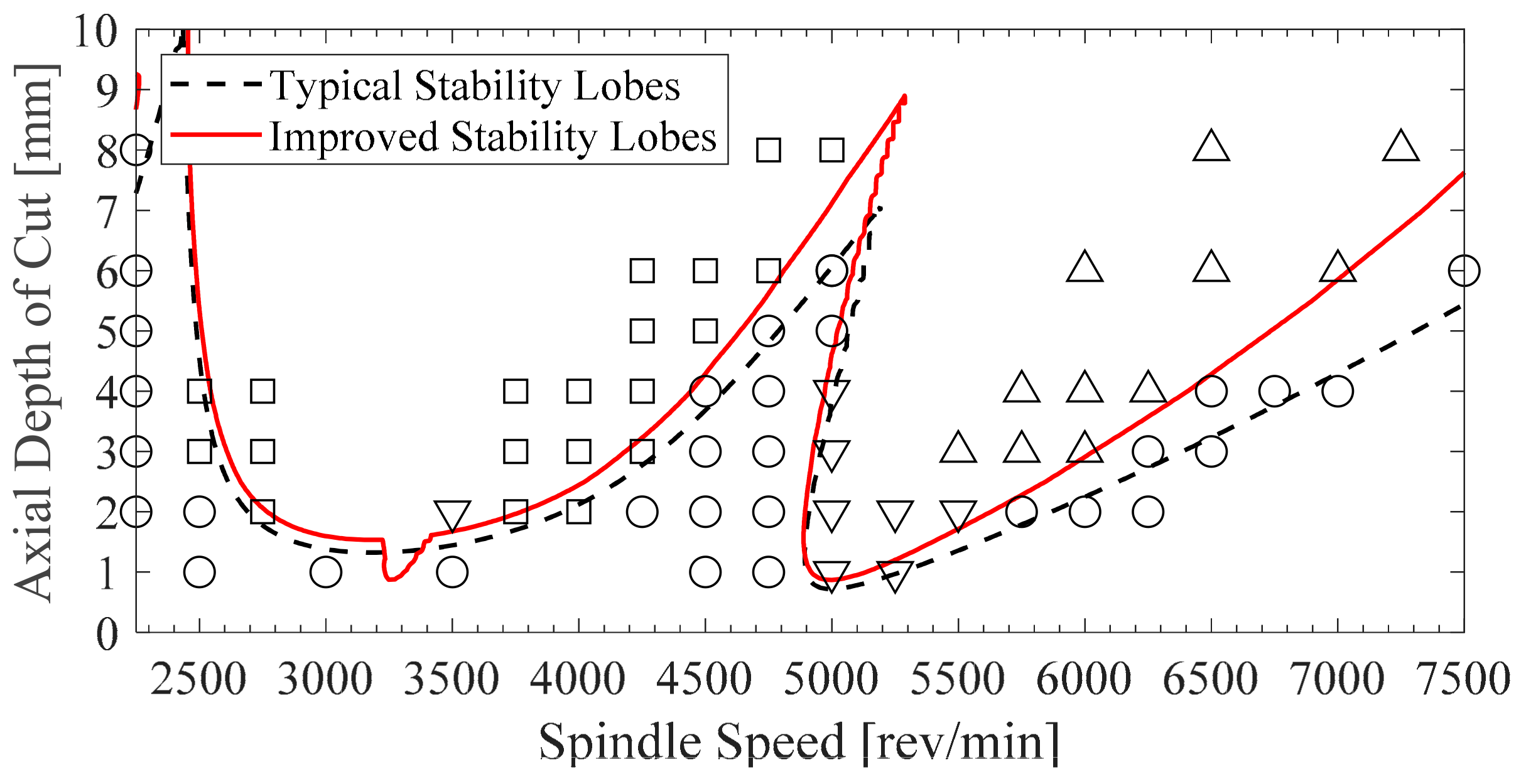
Figure 6.
Convergence of the norm of the 11 × 11 matrix of eigenvalues for all methods.

Figure 7.
Computation time for each combination of parameters (n, ap) of all studied methods.

© 2018 by the authors. Licensee MDPI, Basel, Switzerland. This article is an open access article distributed under the terms and conditions of the Creative Commons Attribution (CC BY) license (http://creativecommons.org/licenses/by/4.0/).
Share and Cite
MDPI and ACS Style
Olvera, D.; Urbikain, G.; Elías-Zuñiga, A.; López de Lacalle, L.N. Improving Stability Prediction in Peripheral Milling of Al7075T6. Appl. Sci. 2018, 8, 1316. https://doi.org/10.3390/app8081316
AMA Style
Olvera D, Urbikain G, Elías-Zuñiga A, López de Lacalle LN. Improving Stability Prediction in Peripheral Milling of Al7075T6. Applied Sciences. 2018; 8(8):1316. https://doi.org/10.3390/app8081316
Chicago/Turabian StyleOlvera, Daniel, Gorka Urbikain, Alex Elías-Zuñiga, and Luis Norberto López de Lacalle. 2018. "Improving Stability Prediction in Peripheral Milling of Al7075T6" Applied Sciences 8, no. 8: 1316. https://doi.org/10.3390/app8081316
Note that from the first issue of 2016, this journal uses article numbers instead of page numbers. See further details here.