Modeling and Control of a 600 kW Closed Hydraulic Wind Turbine with an Energy Storage System


1
Energy and Power Engineering College, Lanzhou University of Technology, Lanzhou 730050, China
2
Key Laboratory of Fluid Machinery and Systems, Gansu Province, Lanzhou 730050, China
*
Author to whom correspondence should be addressed.
Appl. Sci. 2018, 8(8), 1314; https://doi.org/10.3390/app8081314
Submission received: 15 July 2018
/
Revised: 2 August 2018
/
Accepted: 5 August 2018
/
Published: 7 August 2018
(This article belongs to the Special Issue Wind Energy Conversion Systems)
Abstract
:In this paper, an innovative closed hydraulic wind turbine with an energy storage system is proposed. The hydraulic wind turbine consists of the wind rotor, the variable pump, the hydraulic bladder accumulator, the variable motor, and the synchronous generator. The wind energy captured by the wind rotor is converted into hydraulic energy by the variable pump, and then the hydraulic energy is transformed into electrical energy by the variable motor and generator. In order to overcome the fluctuation and intermittence shortcomings of wind power, the hydraulic bladder accumulator is used as an energy storage system in this system to store and release hydraulic energy. A double-loop speed control scheme is presented to allow the wind rotor to operate at optimal aerodynamic performance for different wind speeds and hold the motor speed at the synchronous speed to product constant frequency electrical power regardless of the changes of wind speed and load power. The parameter design and modeling of 600 kW hydraulic wind turbine are accomplished according to the Micon 600 kW wind turbine. Ultimately, time-domain simulations are completed to analyze the dynamic response of the hydraulic wind turbine under the step change conditions of wind speed, rotor speed input, and load power. The simulation results validate the efficiency of the hydraulic wind turbine and speed control scheme presented, moreover, they also show that the systems can achieve the automatic matching among turbine energy, accumulator energy, and generator output energy.
1. Introduction
The energy crisis and environmental pollution have been a threat to human survival and world economic growth because of excessive exploitation and use of fossil fuel. Renewable energy as the best replacement of fossil fuel is widely used in almost all countries in the world to provide energy during the past decades. Among all kinds of renewable energies, wind energy is experiencing rapid development for its clean, abundant, free, and environmentally friendly characteristics [1,2]. The global total wind power industry increased by 12.6% (54.6 GW) in capacity in 2016. The global total growing capacity and China’s cumulative installations were 486.8 GW and 168,732 MW at the end of 2016. The Five-Year Plan for Energy (2016–2020) calls for 210 GW of wind by 2020 [3].
The mechanical gearbox is a troublesome component within the traditional wind turbine, which has high failure rates and causes high maintenance costs [4]. Compared to the wind power with gearbox, the wind turbine with the direct-drive permanent-magnet generator is more attractive for the highest energy yield. However, this is more expensive and heavier [5]. In recent years, the gearless wind turbine with fluid power transmissions has attracted the attention of researchers around the world because of the unique advantages of variable transmission ratio, high power density, and reliability. The use of hydraulic drives not only can remove an AC frequency converter and a voltage transformer, but also make it possible to significantly reduce the weight of the nacelle and tower [6,7]. Ayana et al. established the simulation model of a gearless hydraulic wind energy harvesting and transfer system using the SimHydraulic toolbox in the MATLAB. A prototype of the hydraulic system was made and the experimental results verified the availability of the proposed model [8]. In [9], a simplified model of the NREL 5 MW turbine with a hydrostatic drivetrain was derived and the control scheme and controller were designed to operate over the wind speed range of the wind turbine. The simulation results showed the controller has a satisfactory performance in its entire operating range. The authors in [10] presented a complete mathematical model of the hydraulic transmission used in wind turbines and proposed a valve control system to decrease the pressure and power fluctuations. Simulations under both below and above the rated wind speed displayed that the wind turbine with the hydraulic transmission has the same variable characteristics as the conventional variable speed wind turbines with gear. The paper [11] showed a hydraulic wind power transfer system which is used as a substitution of the traditional mechanical drive. The mathematical modeling of this gearless wind power transfer system was established and its accuracy was confirmed by comparing with test results. The authors in [12] proposed a secondary control hydrostatic transmission (SC-HST), which was used for the wind energy conversion system. A PID controller was designed for motor speed control. The simulation results demonstrated that the relative error of the motor speed was less than 2% and the efficiency of the novel system was 70.4%.
Electric power produced by wind turbines is highly erratic because of the stochastic and intermittent nature of wind. The output instability of electric power will reduce the power quality and affect the planning of power systems. Therefore, an energy storage system will be indispensable for a wind energy conversion system. The investment cost of an energy storage system accounts for a large proportion of the total price of the wind turbine with an energy storage system. The larger the capacity of the energy storage system is, the bigger the total cost becomes. An energy storage system can control wind power plant output and provide additional energy to the power system via storing the excess energy and releasing the stored energy. There are many different forms for storing the wind energy: gravitational potential energy, compressed air, electrochemical energy, chemical energy, and kinetic energy [13]. Martinez-Lucas et al. improved the quality of frequency regulation in isolated power systems by combining a hybrid wind–pumped storage hydropower plant (PSHP) with variable speed wind turbines (VSWT) [14,15]. Battery energy storage systems are regarded as one of the most promising technologies, which can help to overcome the issue mentioned above [16,17]. For a hydraulic wind turbine, compressed air energy storage has a great number of advantages of all of the energy storage forms, which can make full use of hydraulic energy without an energy conversion process and are more suitable for very large scales [18]. Mohsen et al. presented a novel offshore wind turbines with an open compressed air energy storage system. A nonlinear controller was designed to capture maximal wind energy and satisfy power demand. Case studies showed that the storage system not only can downsize the electrical component to 1/5 of the turbine’s capacity, but also can output a constant mean electrical power [19]. Fan et al. investigated the open hybrid wind-tidal turbine with fluid power transmission and energy storage system. The open hydraulic system of these turbines are mainly comprised of a hydraulic pump and a pelton turbine. The simulation results demonstrated that the energy storage system can damp out the power fluctuations and deliver the desired generator power [20,21]. Ammar et al. designed a compressed air energy storage system for the wind turbine with hydrostatic powertrain. The design parameters of the energy storage system, as the compression ratios, the expander ratios, and the air tank size, were chosen based on the simulations to realize the best stable performance [22]. The authors in [23] added an energy storage system into the closed-loop hydraulic system of hydraulic wind turbine to eliminate the randomness and fluctuation of wind power. A proportional valve was adopted to keep the motor speed constant and produce stable frequency electrical energy.
The rotor speed has an important influence on the wind energy absorbed by wind turbine. In order to achieve maximum wind power coefficient, the rotor speed varies with the wind speed, which is determined by the optimal tip speed ratio. Therefore, a novel closed-loop hydraulic system with hydraulic accumulator is presented and applied to the wind energy generation system to realize simultaneously variable speed constant frequency and wind energy storage, as shown in Figure 1.
Given existing research achievement, many researchers have made great contributions to the development of hydraulic wind turbine. However, the study on the dynamic responses of the rotor and motor to the step changes of the wind and rotor speed is seldom found for the closed hydraulic wind turbine with an energy storage system. Meanwhile, the compensation ability of the energy storage system to load power change also needs to be analyzed and validated.
The rest of this paper is constructed as follows. Section 2 details the system configuration and energy flow diagram of the hydraulic wind turbine with an energy storage system. Section 3 depicts the mathematical models of all components in this hydraulic wind turbine. Section 4 presents first a speed control diagram for the rotor and motor speed controls. The speed control strategy is described later. Section 5 shows the main parameters of this hydraulic wind turbine aiming at a Micon 600 KW. Treating the step changes of wind speed, rotor speed input and load power as an input to evaluate the dynamic response performance of the control system. Section 6 concludes this work.
2. System Overview
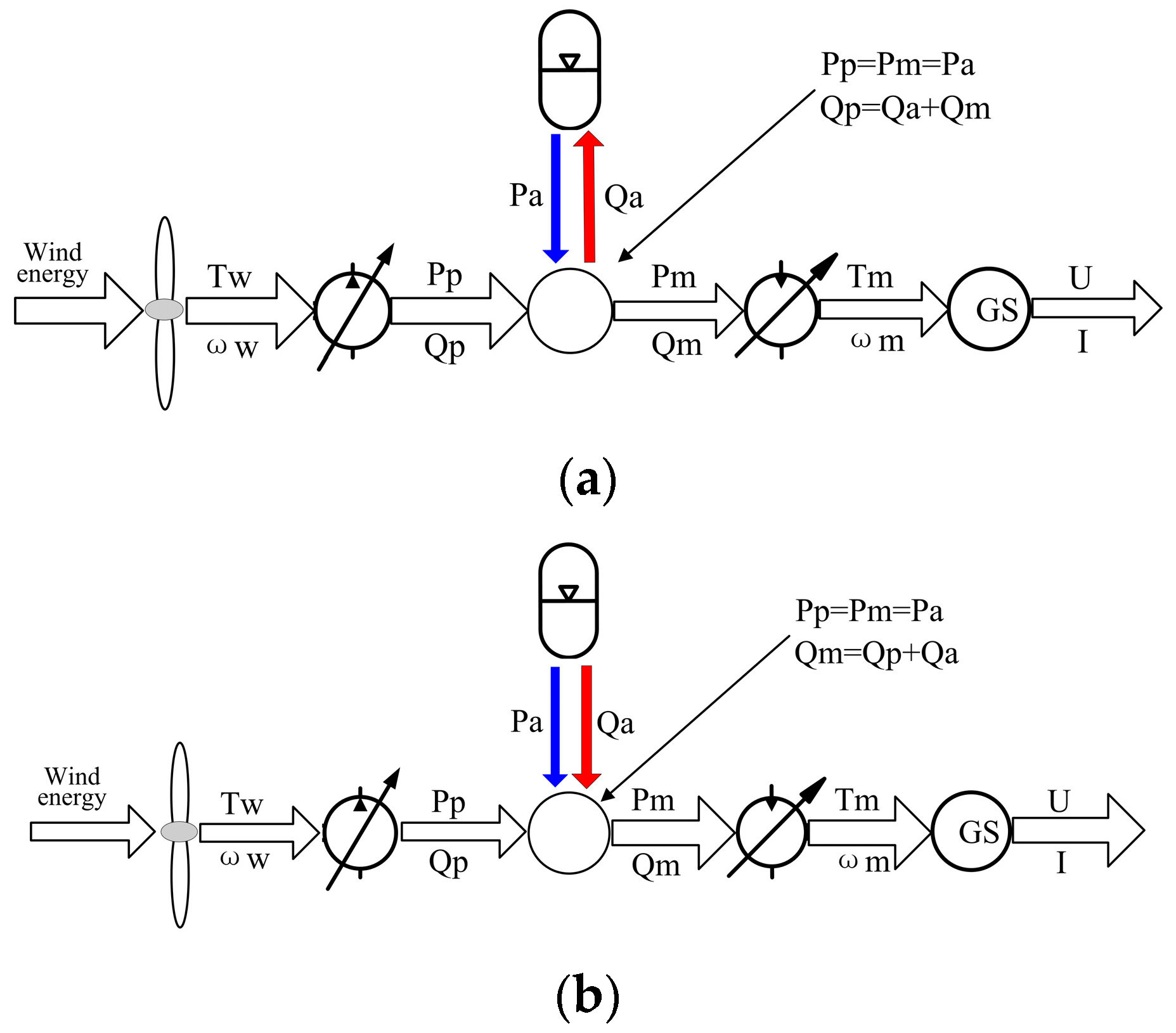
As shown in Figure 1, the closed-loop system of the hydraulic wind turbine with hydraulic accumulator is totally different from that we commonly used. The displacements of the pump and the motor in this hydraulic wind turbine are both variable. But in the most frequently used closed-loop system, there is only one variable component between the pump and motor. The variable pump placed in the nacelle is coupled to the rotor of the wind turbine, through which the hydraulic oil in the low-pressure lines is sucked and pressured into the high-pressure lines. Passing through the check valve, the high pressure oil from the pump flows into the hydraulic accumulator and the variable motor located on the ground. The synchronous generator is connected with the variable motor through the shaft couplings. The boost pump is added to supplement the lost hydraulic oil of the closed-loop system and also complete the heat exchange of the system. There are two relief valves in this system and their function is different. The relief valve connected with the check valve is used to limit the maximum operating pressure of the entire system and ensure the system security. The other relief valve keeps the pressure of the low-pressure lines constant, which will protect the variable pump from damage because of the cavitation. The rotary joint is indispensable to the hydraulic wind turbine, which can help to transmit freely the hydraulic oil from the nacelle to the variable displacement motor without damaging the hydraulic lines when the yaw system is operating. Figure 2 is a diagram that demonstrates the energy conversion and transfer process of the hydraulic wind turbine with the energy storage system. Adding the hydraulic accumulator to the high-pressure lines, the outlet pressure of the pump and the inlet pressure of the motor are determined by that of the hydraulic accumulator. The difference between wind energy captured by wind turbine and the electrical energy generated by the generator decides that the high pressure oil flows into or discharges from the hydraulic accumulator.
3. Mathematical Model
The mathematical submodel of the different components in this hydraulic wind turbine are described separately in the following subsections. This submodel is obtained by deriving the ordinary differential equations that govern the main dynamic behavior of the component. All the submodels should carefully be coupled to establish the model of the whole system.
3.1. Wind Turbine
Wind power is absorbed and converted into mechanical energy by the rotor blades of the wind turbine. The available wind power Pwind and actual output power Pw of the wind turbine are expressed as follows [24]:
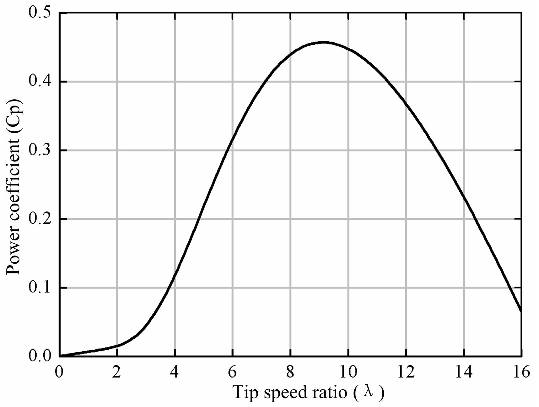
where ρ is the air density. A is the swept area of the rotor blades. vw is the wind speed. Pw is related to Pwind via a power coefficient Cp of the wind turbine, which is a function of the tip speed ratio λ and the pitch angle β (see the Equations (3) and (4)) [24]. According to Betz, the maximum value of Cp is 0.593. The relationship between the power coefficient Cp and the tip speed ratio λ is shown in Figure 3.
The tip speed ratio λ is the quotient of the peripheral velocity to the wind velocity, which is obtained from the formula (5). R is the radius of the rotor blade. ωw is the rotor angular speed. The rotor output torque Tw can be calculated as:
3.2. Variable Pump
In this hydraulic wind turbine, a variable pump is adopted as the hydraulic power component of the closed-loop hydraulic system, which transforms wind power captured by wind turbine into hydraulic energy. The pump speed ωp is equal to the rotor speed ωw because the pump and the rotor are directly connected through the rotor shaft. The pump flow Qp and torque Tp are described as follows:
where ωp and Vp represent the rotational speed and the volumetric displacement of the pump respectively. Ppi and Ppo are the inlet and outlet pressure of the pump.
The dynamic characteristics of the pump variable mechanism can be described by a first-order system. Its transfer function is expressed as:
where Up, Kp, and Tp are the control signal, the pump displacement gain, and the time constant of the pump variable mechanism, respectively. The moment balance equation of the rotor and the pump is established as follows using Newton’s second law:
where Jp is the total inertia of the rotor in wind turbine and the pump. Bp is the total coefficient of viscous friction corresponding.
3.3. Check Valve
The check valve is generally mounted on the oil outlet of the pump in a hydraulic system, which aims at preventing the oil in high-pressure lines from flowing backwards into the pump. The high pressure oil will drive the pump and the rotor blades in the opposite direction without the check valve, which is very unsafe and causes extensive damage to the pump. When the difference between Pcvi and Pcvou is greater than Pcr, the oil can free flow through the check valve. Conversely, the check valve turns off and the oil will not flow in reverse. The flow Qcv of the check valve is computed by the following equation:
where Qcv represents the flow passing through the check valve. Pcvi and Pcvo are the inlet and outlet pressure of the check valve. Pcr and Kcr represent the opening pressure and the pressure-flow coefficient of the check valve, respectively.
3.4. Hydraulic Accumulator
The bladder accumulator is widely used in all kinds of hydraulic systems to store the hydraulic energy, which mainly consists of a steel shell and a rubber bladder. The sketch map of the bladder accumulator is shown in Figure 4. The bladder is impregnated with nitrogen gas. When the pressure of the oil in the line is higher than that of nitrogen gas in the bladder, the bladder is compressed and the pressure of nitrogen rises. The accumulator is charged now and the oil in the line flows into the accumulator. Contrarily, the oil is discharged into the line from the accumulator. The compression of nitrogen gas is assumed to obey the ideal gas law, the relationship between gas pressure P and gas volume V is expressed by the ideal gas equation [25]:
where P0 and V0 represent the pre-charge pressure and the initial volume of the nitrogen gas. Pa and Va are the pressure and volume of the nitrogen gas in the process of compression. Qa represents the accumulator flow. n is the polytropic index. In an isothermal compression, n equals one. In an adiabatic compression, n equals one point four that is used in this paper.
3.5. Relief Valve
The relief valve is the key component of the hydraulic system, which is used to keep the hydraulic system pressure stable or limit the maximum working pressure. When the difference between the inlet pressure Prvi and the outlet pressure Prvo is greater than the cracking pressure Pop, the oil overflows into the tank through the opening formed by the valve core and valve seat of the relief valve. The overflow flow Qrv is computed by the following equation:
where Krv is the pressure-flow coefficient of the relief valve.
3.6. Variable Motor
A variable motor is the actuating component of this hydraulic wind turbine, which converts the hydraulic energy exported by the pump or stored in the accumulator into the mechanical energy required by the synchronous generator. The flow continuity equation of the high-pressure pipeline and the motor can be written as Equations (16) and (17). The output moment equation of the motor can be established as Equation (18) [26]:
where Qm is the flow of the variable motor. V is the total compression volume, which consists of the volume of the oil in the high-pressure pipeline, high pressure chamber of the pump, and the motor. βho represents the effective bulk modulus of hydraulic oil. Dm and ωm represent the displacement and speed of the variable motor. P1 and P2 represent the inlet pressure and outlet pressure of the motor, respectively. Cim and Cem are the internal and the external leakage coefficients of the motor. Jt and Bv represent the total inertia and the coefficient of viscous friction of the rotor in the motor and the generator. Tg is the torque produced by the generator for electric power.
The dynamic characteristics of the variable mechanism of the motor can be seen as [27]:
where Um is the displacement control signal to the variable mechanism. Km represents the motor displacement gain and Tm is the time constant of the variable mechanism.
3.7. Synchronous Generator
A three-phase AC synchronous generator is used in this hydraulic wind turbine to output electrical energy. According to Park transformation and Ohm’s law, voltage balance equations of the rotor and stator in dq0 coordinates are computed as follow [28]:
where Usd and isd represent the stator voltage and current on the Park’s d axis. Usq and isq represent the stator voltage and current on the Park’s q axis. Ra, Rdd, and Rdq represent the stator winding resistance and the damper winding’s resistance. ψsd and ψsq are the stator windings flux linkage. ψdd and ψdq are the damper windings flux linkage. idd and idq are the stator currents of the damper windings.
The flux linkage equation of all winding is constituted as follows. The electromagnetic torque Γ is computed by Equation (29):
where Msf, Msd, Msq, and Mfd represent the mutual inductance coefficient between the two windings. Lsd, Lsq, Lf, Ldd, and Ldq are the inductance coefficient of all windings. p represents the pole pairs.
4. Control Scheme
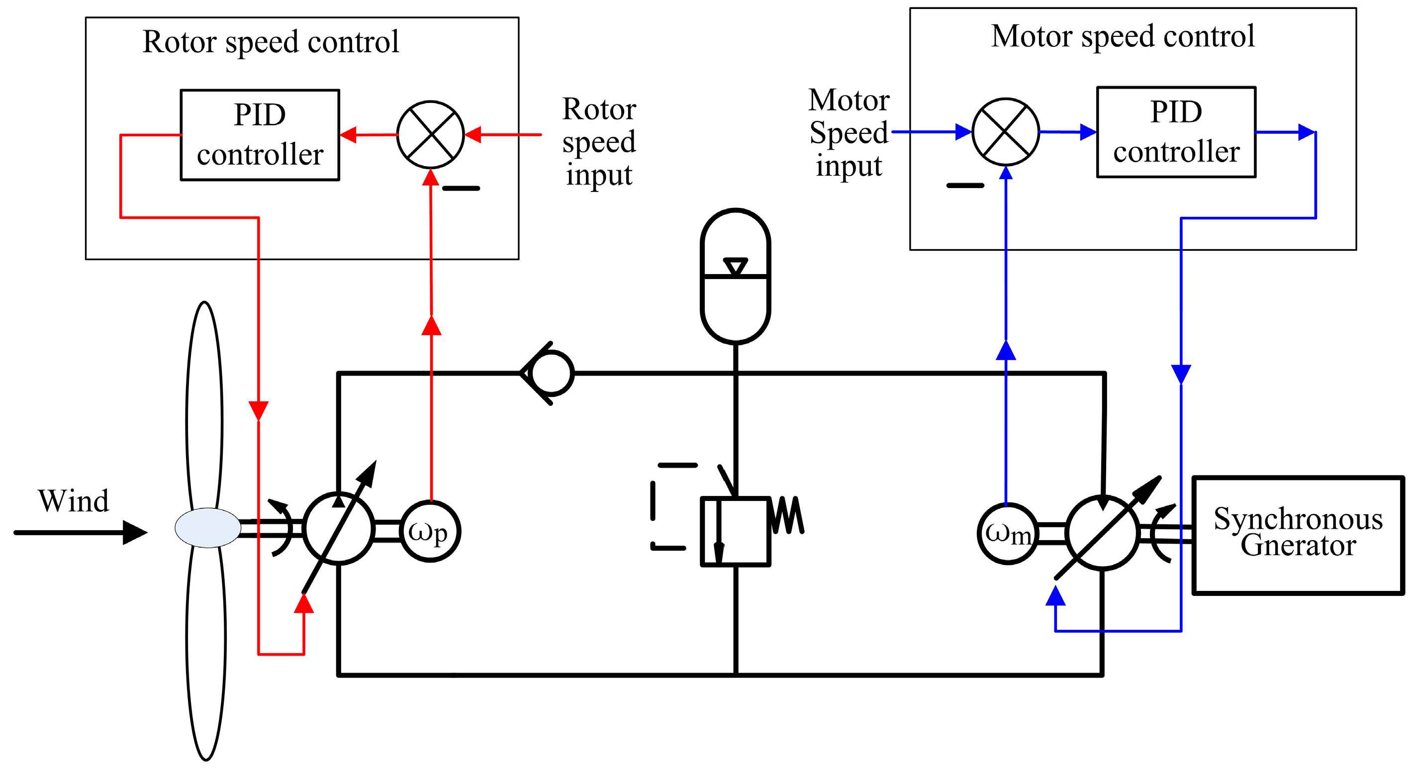
The working pressure of the high-pressure lines is equal to that of the energy storage system after the hydraulic accumulator joining in the hydraulic wind turbine. To rotate the turbine rotor at the optimal speed determined by the wind speed and the rotor blade diameter and keep the motor at the synchronous speed of the synchronous generator, two closed-loop speed controls are proposed in this study. As illustrated in Figure 5, one is the closed-loop control of the rotor speed and the other is that of the motor speed. The two speed control systems have the same structure, but they have different purposes. The rotor speed control system is a follow-up control, which makes the actual speed of the rotor keep pace with the rotor speed input as quickly as possible. The rotor speed input signal varies with wind speed blowing the rotor blades. The motor speed control is a constant value control system, which maintains the motor speed at the synchronous speed despite of the great change of the pressure in the accumulator or the output power of the generator.
The speed control strategy of the hydraulic wind turbine is shown in Figure 6. Taking the case of the rotor speed control, the displacement control process of the variable pump is discussed in detail. It is easy to see that there are two comparisons in the rotor speed control system. One is the torque comparison between the wind torque and hydraulic torque that is the product of accumulator pressure and pump displacement. The other is the speed difference between the rotor speed input and the actual rotor speed.
When wind becomes stronger or accumulator pressure is lower, the torque difference will become positive because the wind torque is more than the hydraulic torque. The pump and rotor acted by the positive torque will accelerate. The actual rotor speed will be greater than the rotor speed input. At the same time, the speed difference becomes negative. The pump displacement raises under the PID control, which causes hydraulic torque increase and decelerates the rotor. The speed difference is close zero owing to the decrease of the rotor speed. The speed deviation of the rotor is zero when the rotor speed decreases to the rotor speed input, meanwhile, the displacement of the pump is maintained. In this way, the rotor speed is kept at the optimal speed desired. The rotor speed will decrease on the condition of an accumulator pressure increase or a wind decrease. The changing direction of the displacement is just opposite. The motor speed control has the same control strategy as the rotor speed control.
5. Simulation and Discussion
5.1. The Design of the Experimental Prototype
5.1.1. Wind Turbine and Variable Pump
A Micon 600 kW wind turbine is chosen and will be turned into the experimental platform of hydraulic wind turbine, as shown in Figure 7. The rotor blades of the wind turbine remain unchanged for absorbing wind energy. The variable pump will be installed in the nacelle by replacing the original gearbox and generator, which transmits the wind energy captured by turbine blades into hydraulic energy. To provide the hydraulic system with high reliability and long life at the same time, the maximum working pressure of this hydraulic system is limited at 210 bars. The parameters of wind turbine and variable pump are listed in Table 1.
5.1.2. Energy Storage System
The bladder accumulator is adopted in the hydraulic wind turbine experimental prototype to store the extra hydraulic energy for its lower costs and fast response. The advantage of the energy storage system is that: when the wind does not provide enough energy for electrical energy, the generator can continue to produce electric energy for a long time with the hydraulic energy stored in the energy storage system. Its main parameters are described in Table 2.
5.1.3. Variable Motor and Synchronous Generator
There are three hydraulic motor-generator units in this system for converting hydraulic energy into electrical energy. According to wind speed, some of the three electricity generation units are thrown into their work. The parameters of the generation unit are demonstrated in Table 3.
5.2. Simulation Results
The mathematical models of the hydraulic wind turbine studied in this paper are established in MATLAB software. In order to maximize the power coefficient Cp of wind turbine, the rotor speed is supposed to remain a constant that would change with wind speed change; besides, the output power of the synchronous generator matches the load power. Therefore, the simulations under the step changes of wind speed, rotor speed input, and generator output power are conducted to validate the effectiveness of the proposed control scheme and indicate the flow of wind power absorbed by the rotor blades.
5.2.1. Step Changes of Wind Speed and Rotor Speed Input
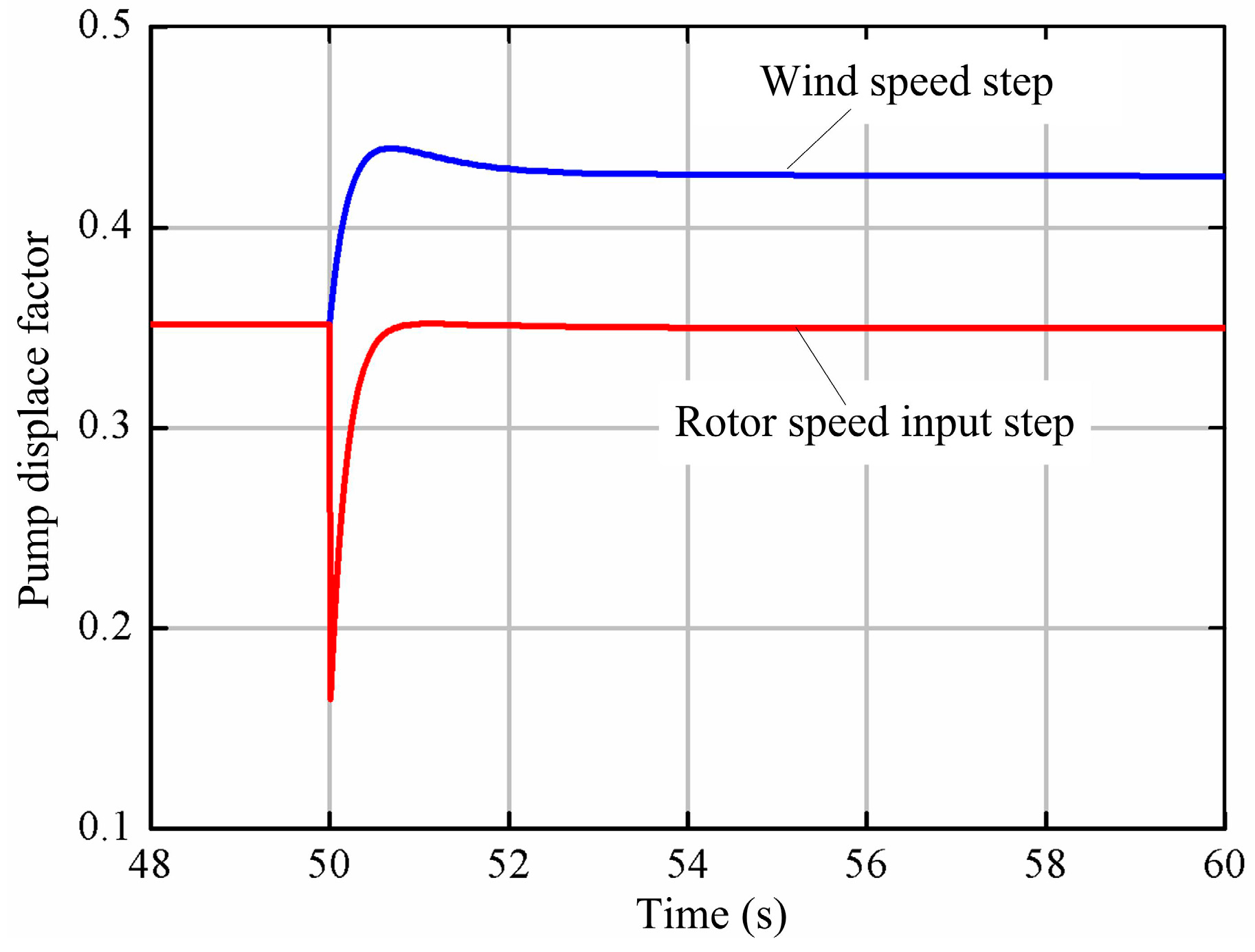
The change curves of the wind and rotor speed input are shown in Figure 8. The wind speed changes suddenly from 8 m/s to 9 m/s and the rotor speed input increases from 24 r/min to 26 r/min, which both occur at 50 s. The displacement factors of the variable pump in two cases are shown in Figure 9. As shown, the pump displacement factor rises from 0.35 to 0.43 when the wind speed suddenly increases. The variation trend of the pump displacement factor is the opposite when the rotor speed input has a sudden increase, which decreases rapidly from 0.35 to 0.17 and gets back to the begin value 0.35. It can be seen that the displacement factor gradually decreases in both cases as time goes on.
Figure 10 shows that the pump speed will increase faster to 24.6 r/min owing to the wind speed step. The hydraulic counter-torque acting on the variable pump becomes big for the increase of the pump displacement. The variable pump begins to decelerate when the hydraulic counter-torque is greater than the wind torque. Finally, the pump speed returns to 24 r/min. When the rotor speed input step occurs, the pump accelerates on account of the decrease of the pump displacement. It reaches finally at 26 r/min after a small overshoot.
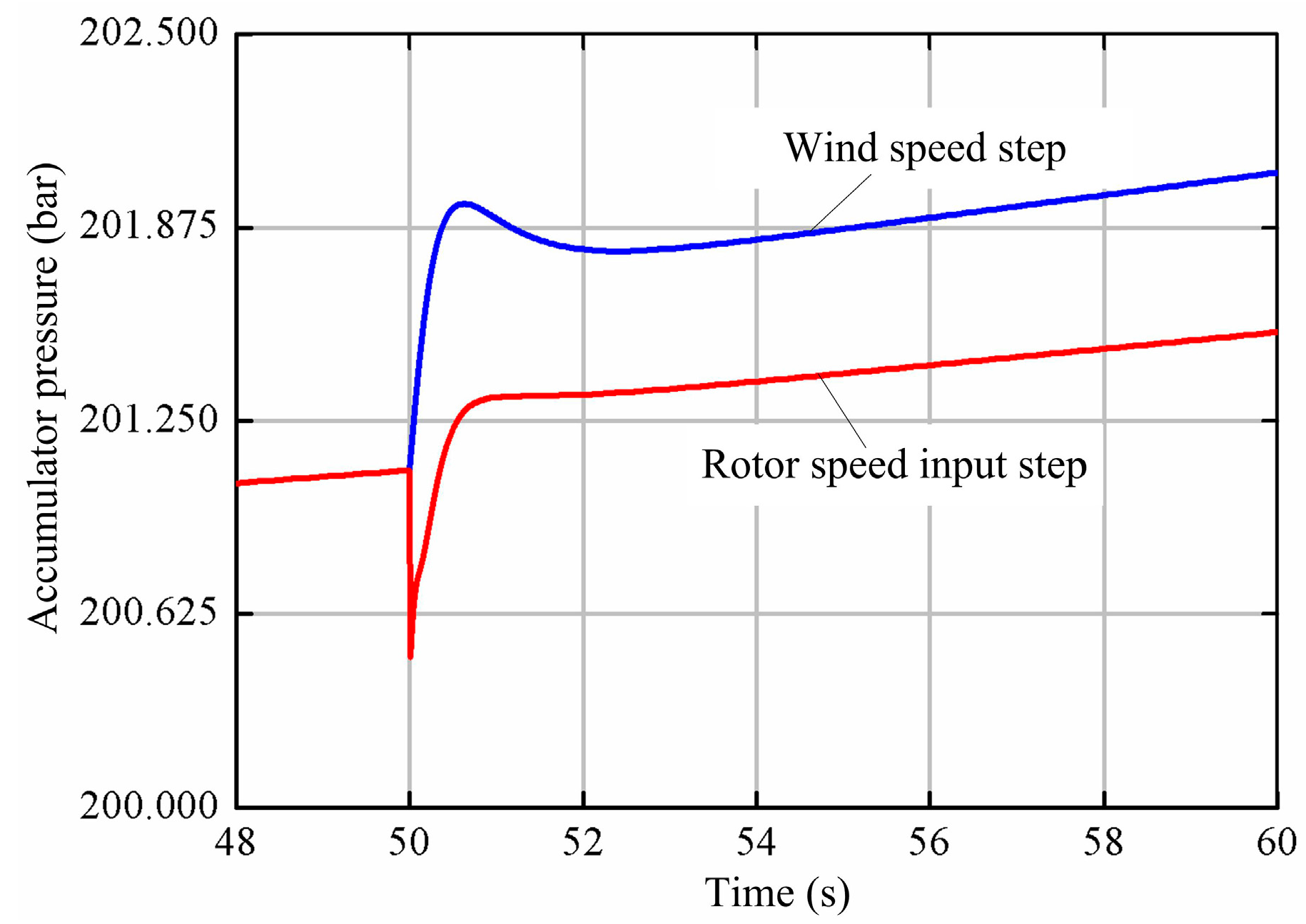
From Figure 11, Figure 12 and Figure 13, it can be shown that the flow curves of the pump and the accumulator show the same trends as that of the pump displacement. The pump flow with the wind speed step is greater than that with the rotor speed step at 75 L/min. The discharge flow of the accumulator has the maximal value 130 L/min when the rotor speed arises. The accumulator pressure in both cases rises gradually because the accumulator is in the state of charge in most of the time. The accumulator pressure in the wind speed step increases much more rapidly as a result of more charge flow.
Figure 14 shows that the power coefficient and tip speed ratio in both cases. As shown, the tip speed ratio increases from 6.8 to 7.5 when the rotor speed changes from 24 r/min to 26 r/min. Corresponding, the power coefficient increases from 0.37 to 0.42. It can be seen that the tip speed ratio reduces from 6.8 to 6.1 as the wind speed arises. The power coefficient decreases to 0.33 accordingly.
As shown in Figure 15, the wind power changes from 470 kW to 675 kW as the wind speed varies from 8 m/s to 9 m/s. The turbine power captured by the rotor blades is 185 kW when the wind speed and the rotor speed are 8 m/s and 24 r/min. As the wind speed increases to 9 m/s, the turbine power is equal to 223 kW. As the wind turbine speed accelerates to 26 r/min, the turbine power reaches 199 kW.
5.2.2. Step Change of Load Power
As shown in Figure 16, the load power increases from 100 kW to 300 kW at 50 s. Figure 17 shows the displacement factors of the pump and the motor. It can be seen that the motor displacement gets immediately bigger from 0.26 to 0.76 for the change of the load power. Simultaneously, the pump displacement rises first to 0.365 in a short time and then decreases to 0.358. Later, it has a creeping increase.
Figure 18 shows the pump flowrate, the accumulator flowrate and the motor flowrate. As shown, the motor flowrate changes from 400 L/min to 1150 L/min. The pump flowrate remains approximately constant during the change process of the load power. About one third of the pump flowrate 566 L/min flows into the hydraulic accumulator when the load power is 100 kW. After the load power increases to 300 kW, the hydraulic accumulator discharges the high-pressure oil to complement the shortage of the pump flowrate. From Figure 19, it can be shown that the power changes of the pump, the accumulator and the generator is essentially in agreement with the flowrate changes.
Figure 20 shows the pressure of the pump outlet, the accumulator outlet, and the motor inlet. The difference between the pump outlet pressure and the motor inlet pressure is always a fixed value, which is the pressure loss of the check valve. The accumulator pressure gradually decreases owing to the oil discharge after 50 s. Besides, the accumulator pressure starts to be greater than the pump outlet pressure. The pressure loss between the accumulator and the motor becomes greater on account of the increases of the accumulate flowrate and the pressure loss.
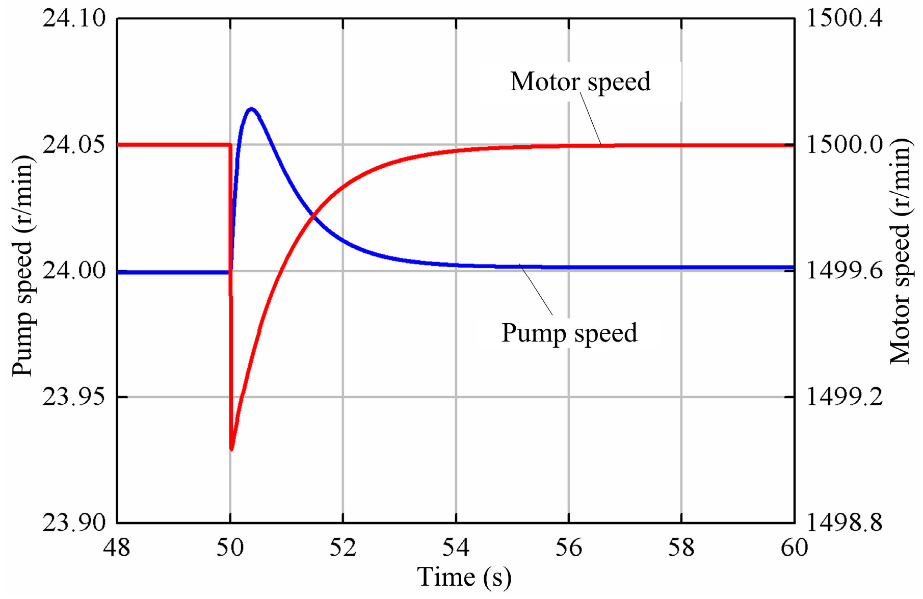
From Figure 21, it can be shown that the pump speed rises first for the decrease of the pump outlet pressure and then falls to the old value for the increase of the pump displacement. The motor speed undergoes a short-term drop to 1499 r/min and returns to 1500 r/min after about 2 s.
6. Conclusions
The Micon 600 kW wind turbine is selected for transforming wind energy into mechanical energy. A hydraulic bladder accumulator is used as the energy storage device in this hydraulic wind turbine to store the surplus of the wind energy extracted by the rotor blades and solve the problem of the wind power output fluctuation and intermittence. The design of hydraulic principle diagram and the main components are completed. The mathematical equations of all the components are obtained and the simulation model of the entire system based on MATLAB is constructed. Two PID controllers are adopted in the rotor and motor speed control system to make the rotor speed reach quickly the expectation and keep the motor speed constant all the time.
The response simulations and analyses of the hydraulic wind turbine under wind speed step, rotor speed input step and load power step are carried out. When wind speed increases from 8 m/s to 9 m/s, the pump speed is maintained at 24 r/min by means of the pump displacement increase. The turbine energy becomes large under the combined effect of the power coefficient decrease and the wind power raise. When the rotor speed rises from 24 r/min to 26 r/min, the pump raises the operating speed by diminishing its displacement. The power coefficient increases as the tip speed ratio become large. When the load power varies suddenly from 100 kW to 300 kW, the motor raises it’s displacement to meet the need of more torque for power generation.
Simulation results show the innovative closed hydraulic wind turbine not only can make the rotor work in an optimal speed for the sake of maximum wind energy capture, but also can keep the motor speed at the constant value for constant frequency of electric energy generated by this hydraulic wind turbine. Furthermore, the energy storage system can automatically store or release hydraulic energy for eliminating the energy mismatch between turbine energy and load power in any case. Besides, the further experimental studies basing on the hydraulic wind turbine experimental platform are necessary to confirm the accuracy and reliability of simulating results.
Author Contributions
L.W. conceived the research; Z.L. and Y.T. achieved the simulation model and control principle design; L.W. and Z.L. completed model verification and wrote the paper together; Y.Z. and G.W. performed the arrangement and analysis of the simulation data; L.W. critically revised the paper and provided many valuable and constructive suggestions.
Funding
This research was funded by the National Natural Science Fund Project of China (51765033), the Gansu Provincial Science and Technology Major Project of China (17ZD2GA010), the Gansu Provincial Natural Science Foundation of China (17JR5RA127) and the Gansu Provincial Natural Science Foundation of China (18JR3RA155).
Conflicts of Interest
The authors declared no potential conflicts of interest with respect to the research, authorship, and publication of this article.
References
- Cheng, M.; Zhu, Y. The state of the art of wind energy conversion systems and technologies: A review. Energy Convers. Manag. 2014, 88, 332–347. [Google Scholar] [CrossRef]
- BoroumandJazi, G.; Rismanchi, B.; Saidur, R. Technical characteristic analysis of wind energy conversion systems for sustainable development. Energy Convers. Manag. 2013, 69, 87–94. [Google Scholar] [CrossRef]
- Global Wind Energy Council (GWEC). Global Wind Report: Annual Market Update; GWEC: Brussels, Belgium, 2016. [Google Scholar]
- Ribrant, J.; Bertling, L. Survey of failures in wind power systems with focus on Swedish wind power plants during 1997–2005. In Proceedings of the 2007 IEEE Power Engineering Society General Meeting, Tampa, FL, USA, 24–28 June 2007. [Google Scholar]
- Polinder, H.; Van der Pijl, F.F.; De Vilder, G.J.; Tavner, P.J. Comparison of direct-drive and geared generator concepts for wind turbines. IEEE Trans. Energy Convers. 2006, 21, 725–733. [Google Scholar] [CrossRef]
- Diepeveen, N.F.B.; Jarquin Laguna, A. Dynamic modeling of fluid power transmissions for wind turbines. In Proceedings of the EWEA Offshore 2011 Conference, Amsterdam, The Netherlands, 29 November–1 December 2011. [Google Scholar]
- Cai, M.; Wang, Y.; Jiao, Z.; Shi, Y. Review of fluid and control technology of hydraulic wind turbines. Front. Mech. Eng. 2017, 12, 312–320. [Google Scholar] [CrossRef] [Green Version]
- Pusha, A.; Izadian, A.; Hamzehlouia, S.; Girrens, N.; Anwar, S. Modeling of gearless wind power transfer. In Proceedings of the 2011 37th Annual Conference on IEEE Industrial Electronics Society (IECON), Melbourne, Australia, 7–10 November 2011. [Google Scholar]
- Dolan, B.; Aschemann, H. Control of a wind turbine with a hydrostatic transmission—An extended linearisation approach. In Proceedings of the 2012 17th International Conference on Methods and Models in Automation and Robotics (MMAR), Miedzyzdrojie, Poland, 27–30 August 2012. [Google Scholar]
- Skaare, B.; Hörnsten, B.; Nielsen, F.G. Modeling, simulation and control of a wind turbine with a hydraulic transmission system. Wind Energy 2013, 16, 1259–1276. [Google Scholar] [CrossRef]
- Izadian, A.; Hamzehlouia, S.; Deldar, M.; Anwar, S. A hydraulic wind power transfer system: Operation and modeling. IEEE Trans. Sustain. Energy 2014, 5, 457–465. [Google Scholar] [CrossRef]
- Do, H.; Ahn, K. A Study of Wind Energy Conversion System by a Secondary Control Hydrostatic Transmission. J. Drive Control 2013, 10, 21–28. [Google Scholar] [CrossRef] [Green Version]
- Díaz-González, F.; Sumper, A.; Gomis-Bellmunt, O.; Villafáfila-Robles, R. A review of energy storage technologies for wind power applications. Renew. Sustain. Energy Rev. 2012, 16, 2154–2171. [Google Scholar] [CrossRef]
- Martínez-Lucas, G.; Sarasúa, J.I.; Sánchez-Fernández, J.Á. Frequency Regulation of a Hybrid. Wind–Hydro Power Plant in an Isolated Power System. Energies 2018, 11, 239. [Google Scholar] [CrossRef]
- Martínez-Lucas, G.; Sarasúa, J.I.; Sánchez-Fernández, J.Á. Eigen analysis of wind–hydro joint frequency regulation in an isolated power system. Int. J. Electr. Power Energy Syst. 2018, 103, 511–524. [Google Scholar] [CrossRef]
- Weitzel, T.; Glock, C.H. Energy management for stationary electric energy storage systems: A systematic literature review. Eur. J. Oper. Res. 2018, 264, 582–606. [Google Scholar] [CrossRef]
- Marchi, B.; Pasetti, M.; Zanoni, S. Life cycle cost analysis for BESS optimal sizing. Energy Procedia 2017, 113, 127–134. [Google Scholar] [CrossRef]
- Vaezi, M.; Izadian, A. Energy storage techniques for hydraulic wind power systems. In Proceedings of the 2014 International Conference on Renewable Energy Research and Application (ICRERA), Milwaukee, WI, USA, 19–22 October 2014. [Google Scholar]
- Saadat, M.; Shirazi, F.A.; Li, P.Y. Modeling and control of an open accumulator Compressed Air Energy Storage (CAES) system for wind turbines. Appl. Energy 2015, 137, 603–616. [Google Scholar] [CrossRef]
- Fan, Y.; Mu, A.; Ma, T. Study on the application of energy storage system in offshore wind turbine with hydraulic transmission. Energy Convers. Manag. 2016, 110, 338–346. [Google Scholar] [CrossRef]
- Fan, Y.; Mu, A.; Ma, T. Modeling and control of a hybrid wind-tidal turbine with hydraulic accumulator. Energy 2016, 112, 188–199. [Google Scholar] [CrossRef]
- Ali, A.E.; Libardi, N.C.; Anwar, S.; Izadian, A. Design of a compressed air energy storage system for hydrostatic wind turbines. AIMS Energy 2018, 6, 229–244. [Google Scholar] [CrossRef]
- Liu, Z.; Yang, G.; Wei, L.; Yue, D. Variable speed and constant frequency control of hydraulic wind turbine with energy storage system. Adv. Mech. Eng. 2017, 9, 1–10. [Google Scholar] [CrossRef]
- Heier, S. Grid Integration of Wind Energy: Onshore and Offshore Conversion Systems, 3rd ed.; John Wiley & Sons: Chichester, UK, 2014; pp. 43–44. ISBN 978-1-119-96294-6. [Google Scholar]
- Xu, M.; Yu, X.; Wu, X.M.; Chen, G.J. State-space modeling and analysis of power assist unit-based variable-speed pump-controlled-motor drive system. J. Braz. Soc. Mech. Sci. Eng. 2018, 40, 1–8. [Google Scholar] [CrossRef]
- Merritt, H. Hydraulic Control Systems; John Wiley & Sons: Hoboken, NJ, USA, 1991; pp. 152–156. ISBN 978-0-471-59617-2. [Google Scholar]
- Jen, Y.; Lee, C. Robust speed control of a pump-controlled motor system. IEE Proc. D Control Theory Appl. 1992, 139, 503–510. [Google Scholar] [CrossRef]
- Hernandez, R.G.; Ramirez, R.G. Modeling and control of a wind turbine synchronous generator. In Proceedings of the Electronics, Robotics and Automotive Mechanics Conference (CERMA), Cuernavaca, Mexico, 15–18 November 2011. [Google Scholar]
Figure 1.
Schematic diagram of the closed hydraulic wind turbine with energy storage system.
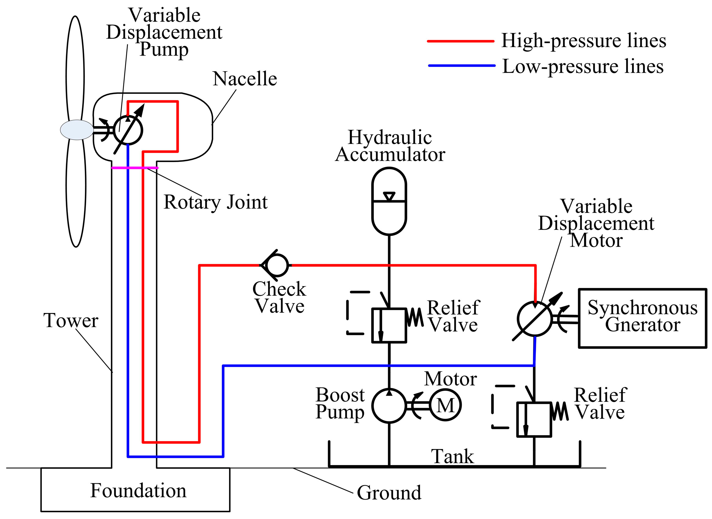
Figure 2.
Energy conversion and transfer chart of the hydraulic wind turbine. (a) Hydraulic oil flowing into hydraulic accumulator; (b) hydraulic oil discharging from hydraulic accumulator.
Figure 2.
Energy conversion and transfer chart of the hydraulic wind turbine. (a) Hydraulic oil flowing into hydraulic accumulator; (b) hydraulic oil discharging from hydraulic accumulator.

Figure 3.
The curve of the power coefficient versu the tip speed ratio.

Figure 4.
Sketch map of the bladder accumulator.
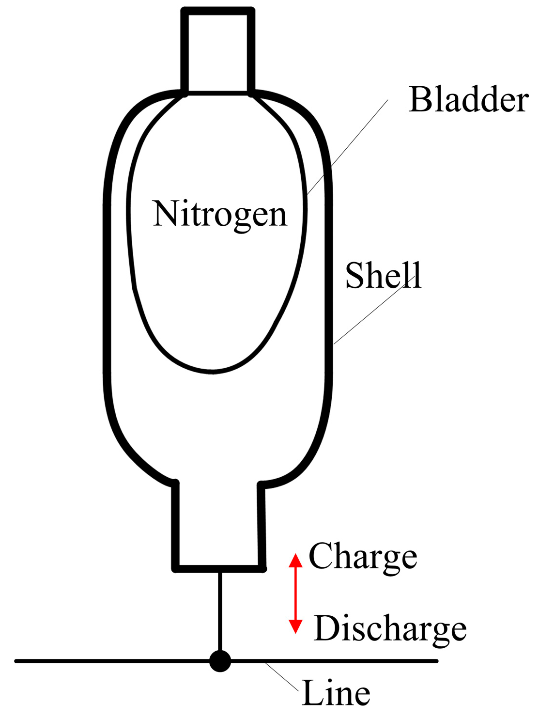
Figure 5.
Speed control diagram of the closed hydraulic wind turbine with energy storage system.

Figure 6.
Speed control strategy of the rotor and motor.
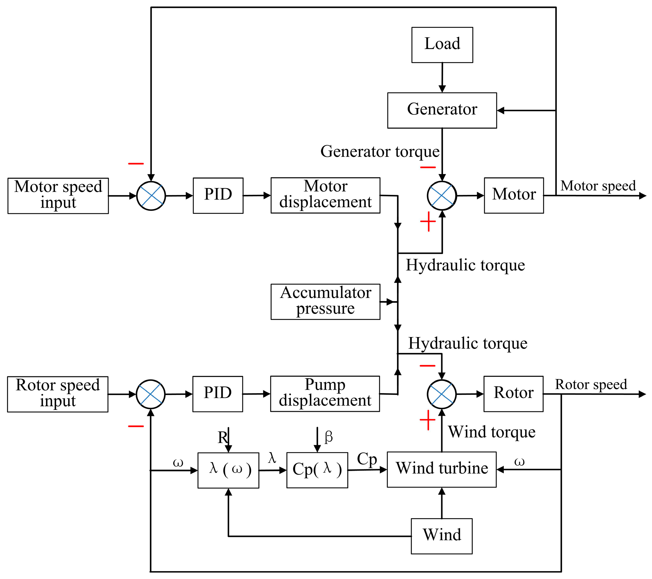
Figure 7.
The Micon 600 kW wind turbine experimental platform.
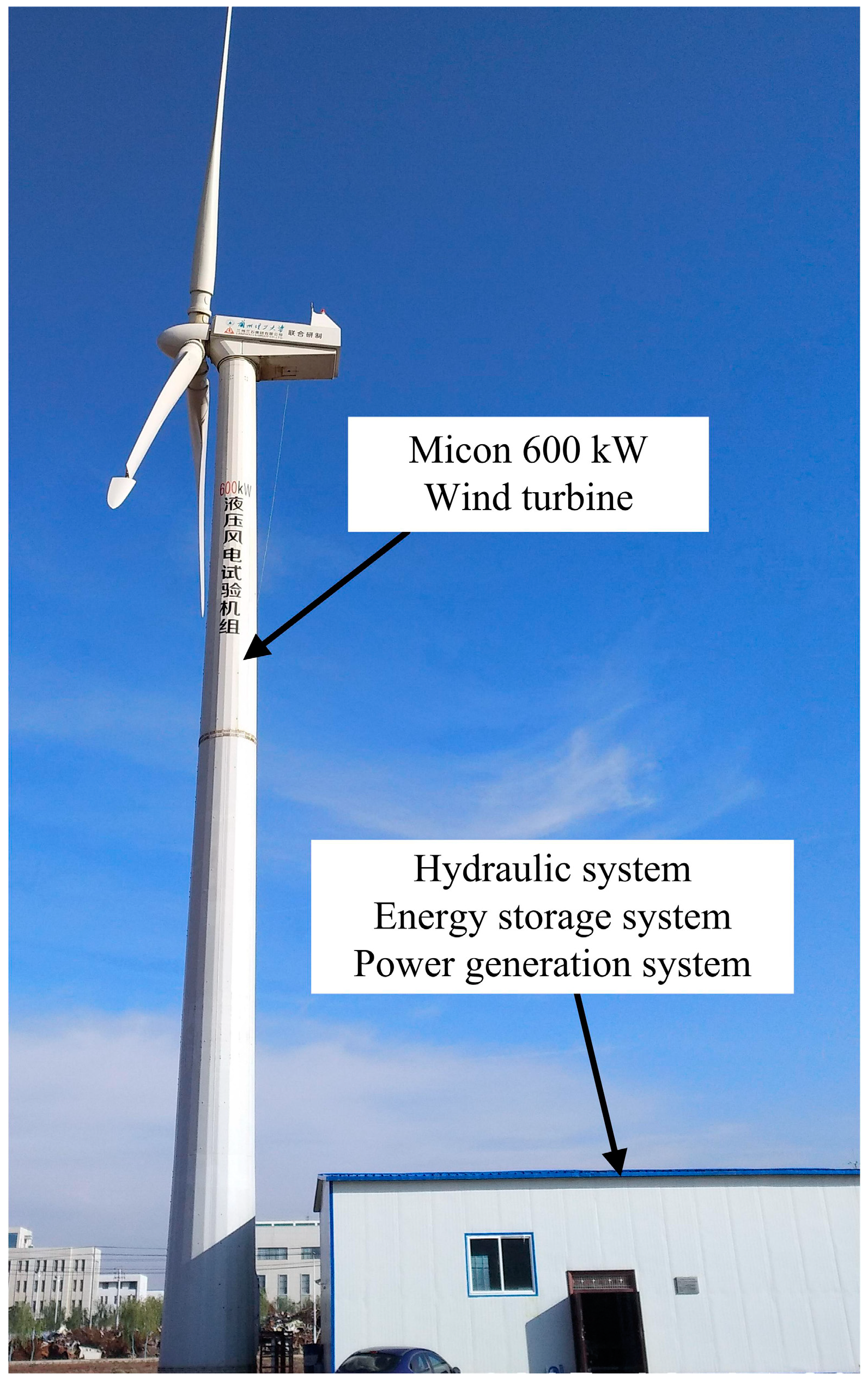
Figure 8.
Wind speed step and rotor speed input step.
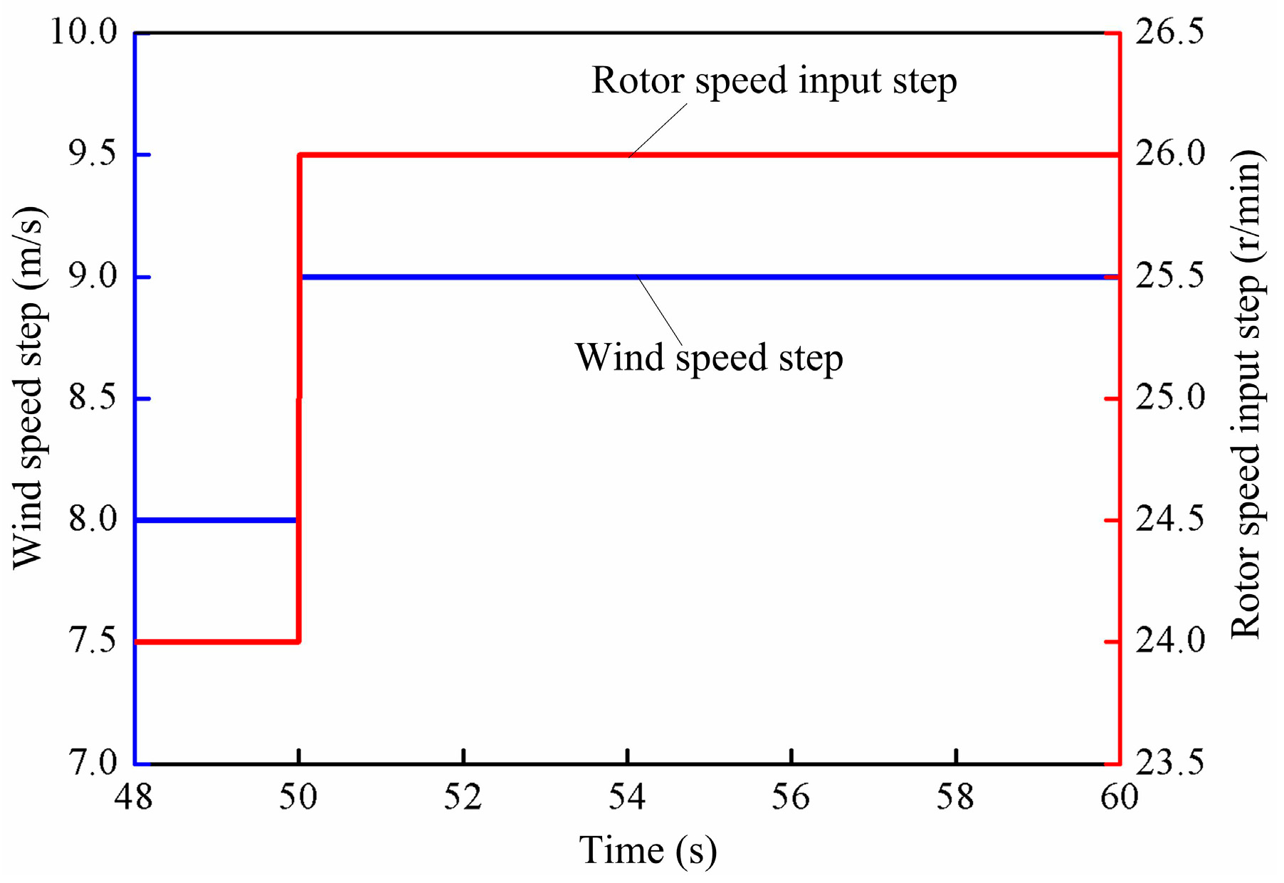
Figure 9.
Pump displacement factor.

Figure 10.
Pump speed.
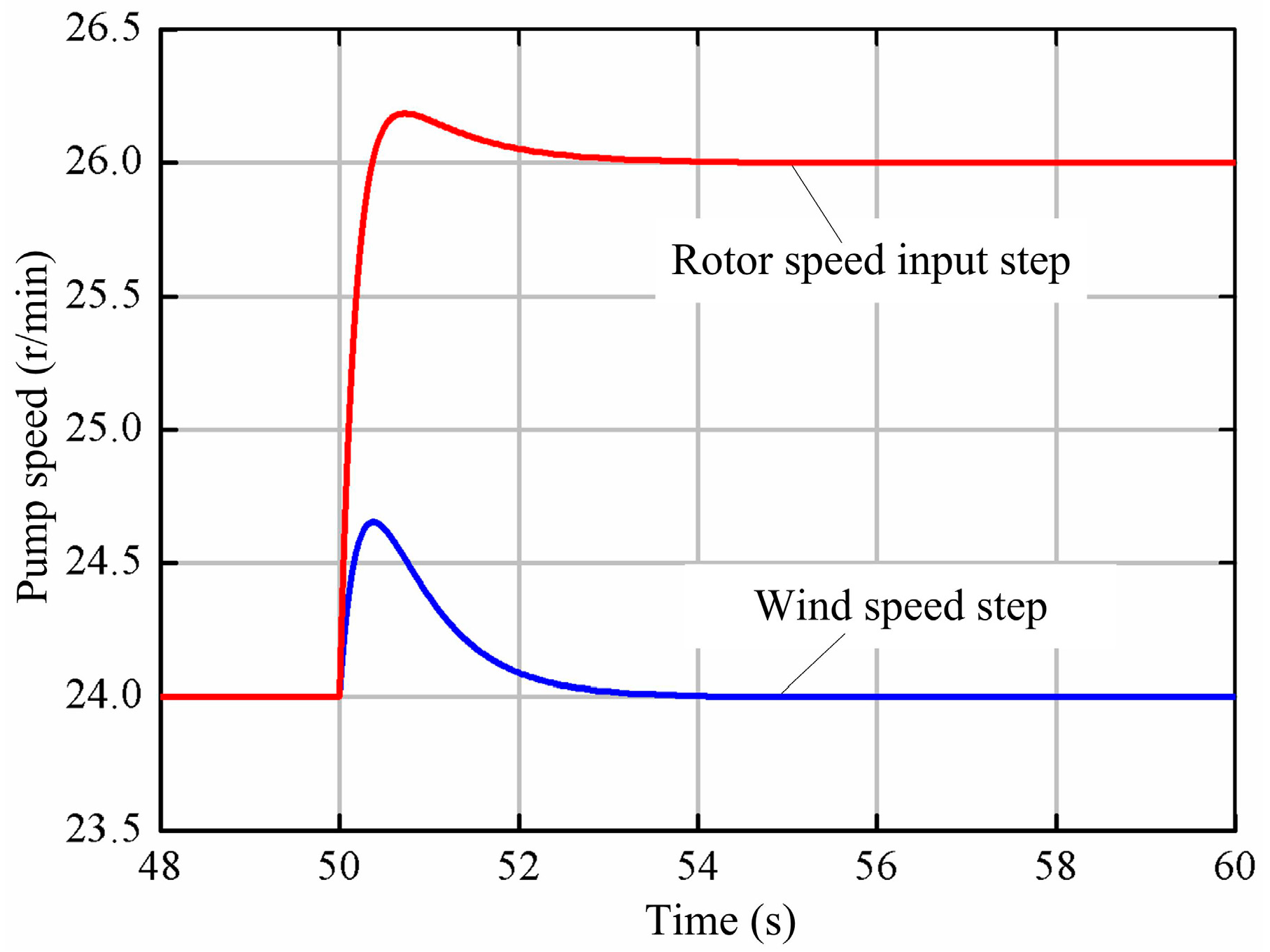
Figure 11.
Pump flow rate.
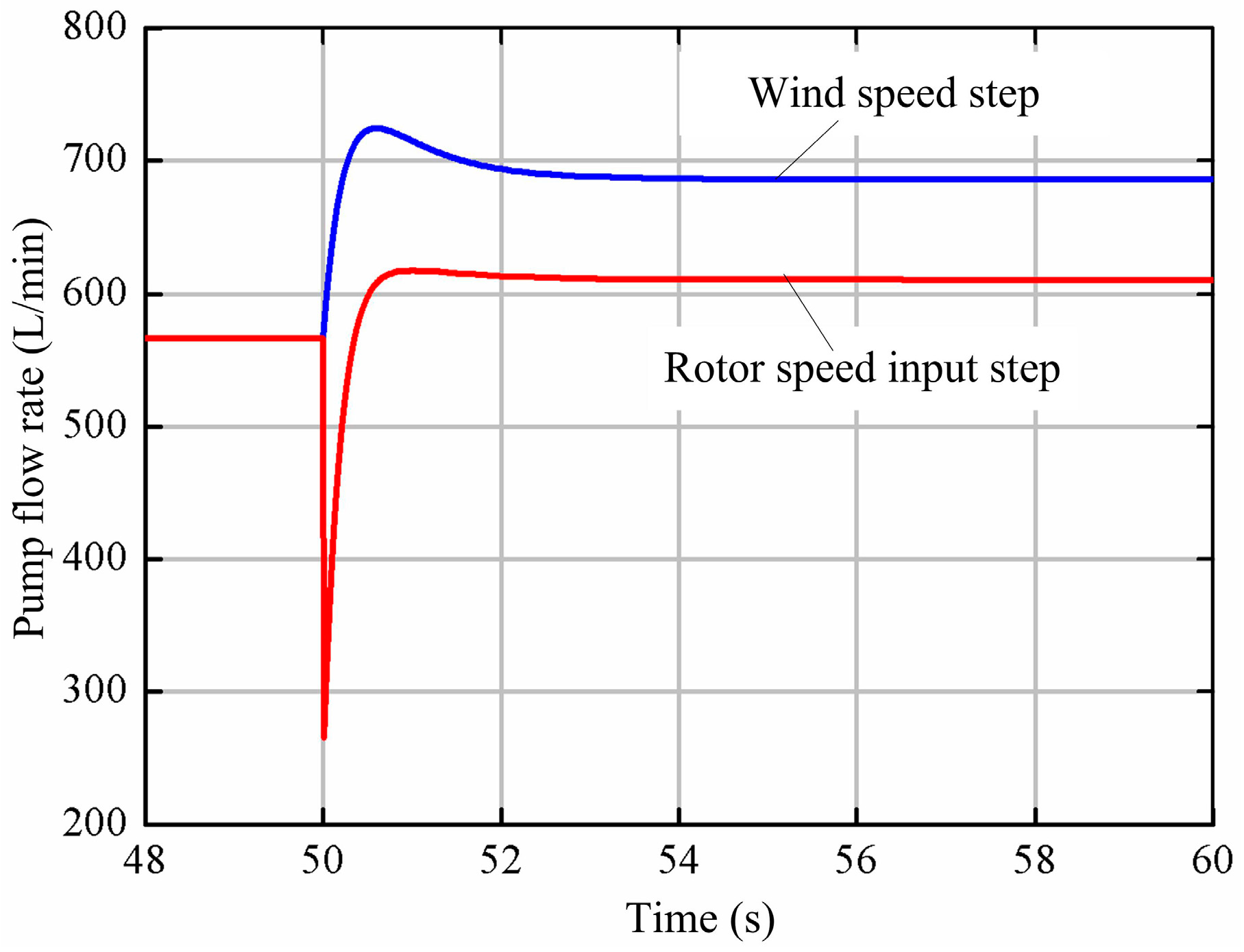
Figure 12.
Accumulator flow rate.
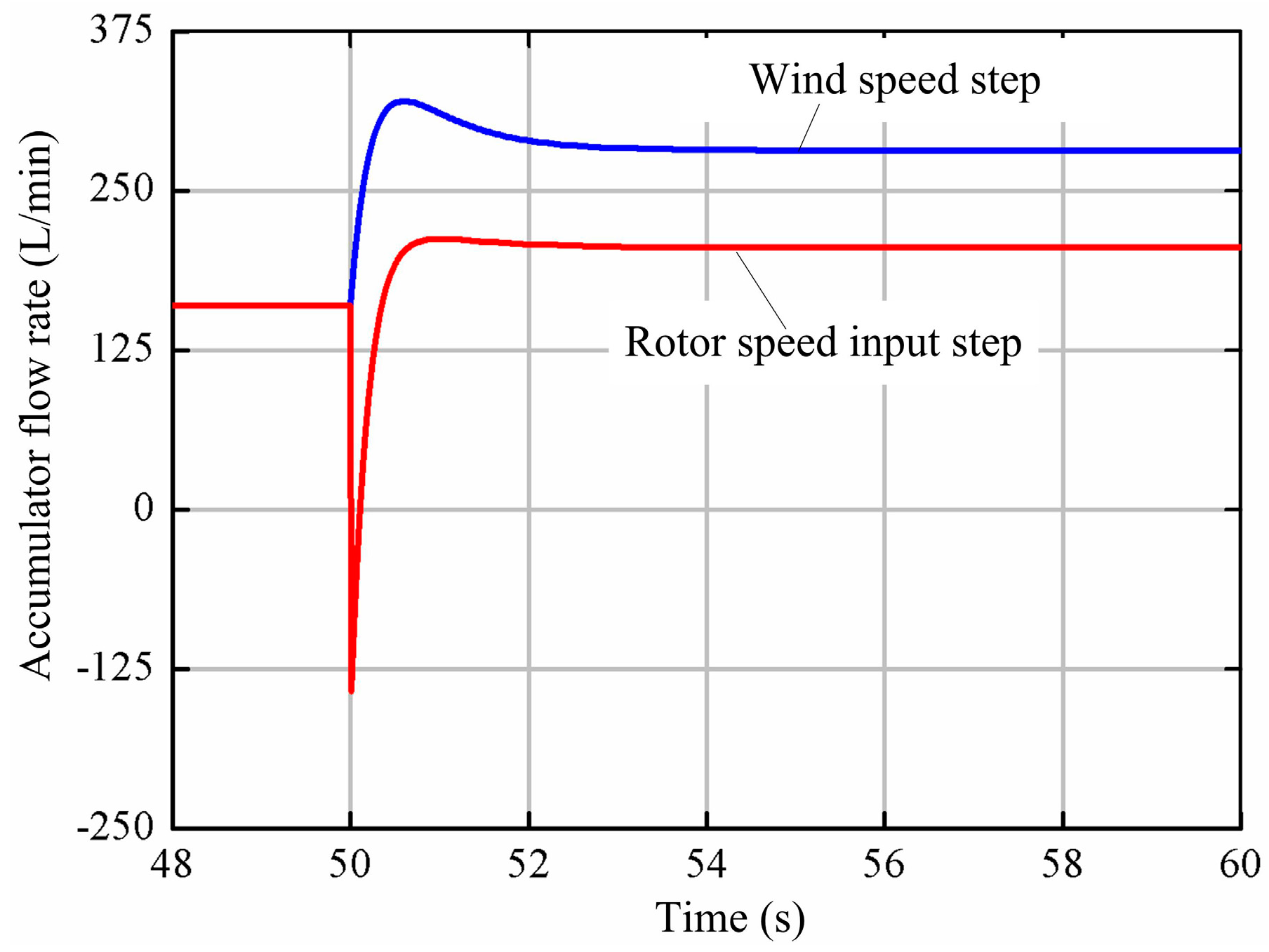
Figure 13.
Accumulator pressure.

Figure 14.
Power coefficient and tip speed ratio.
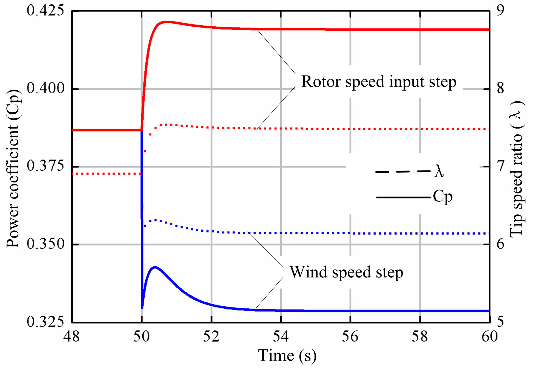
Figure 15.
Wind power and turbine power.
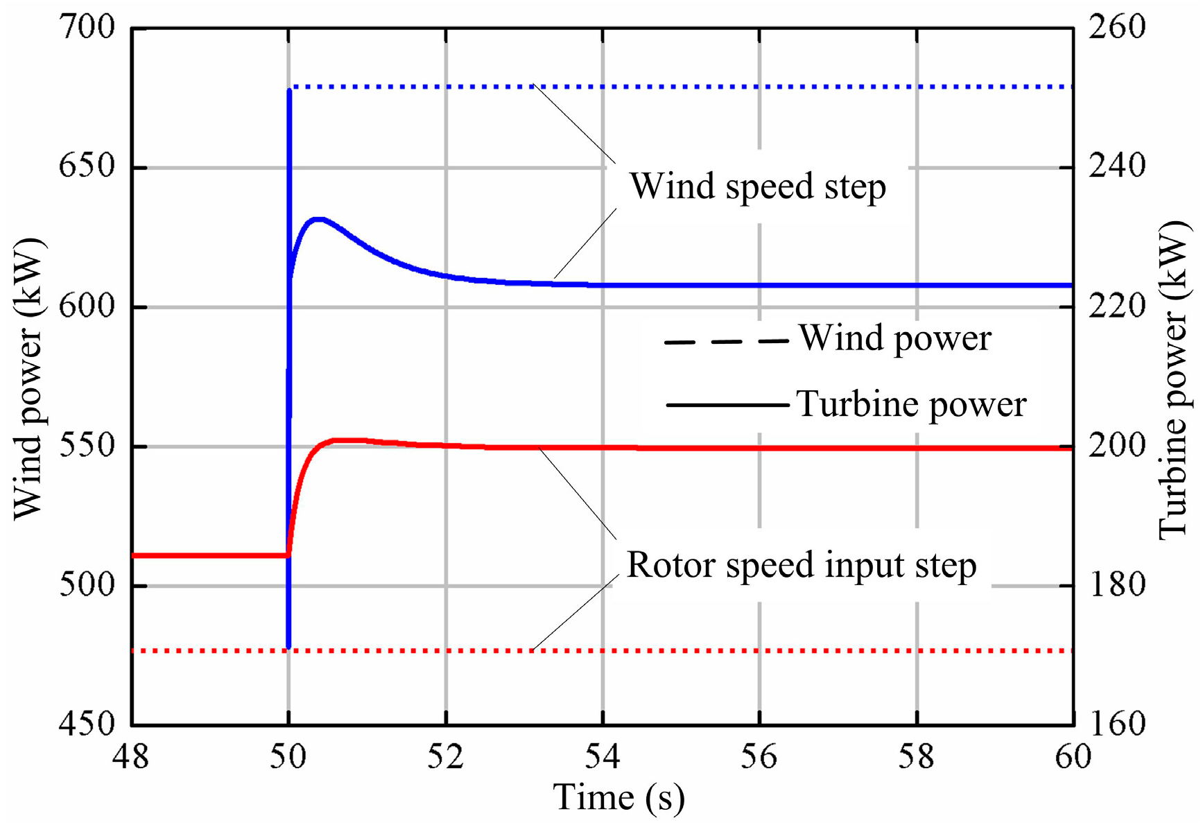
Figure 16.
Load power step.
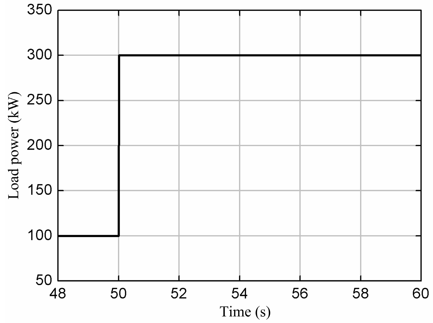
Figure 17.
Pump displacement factor and motor displacement factor.
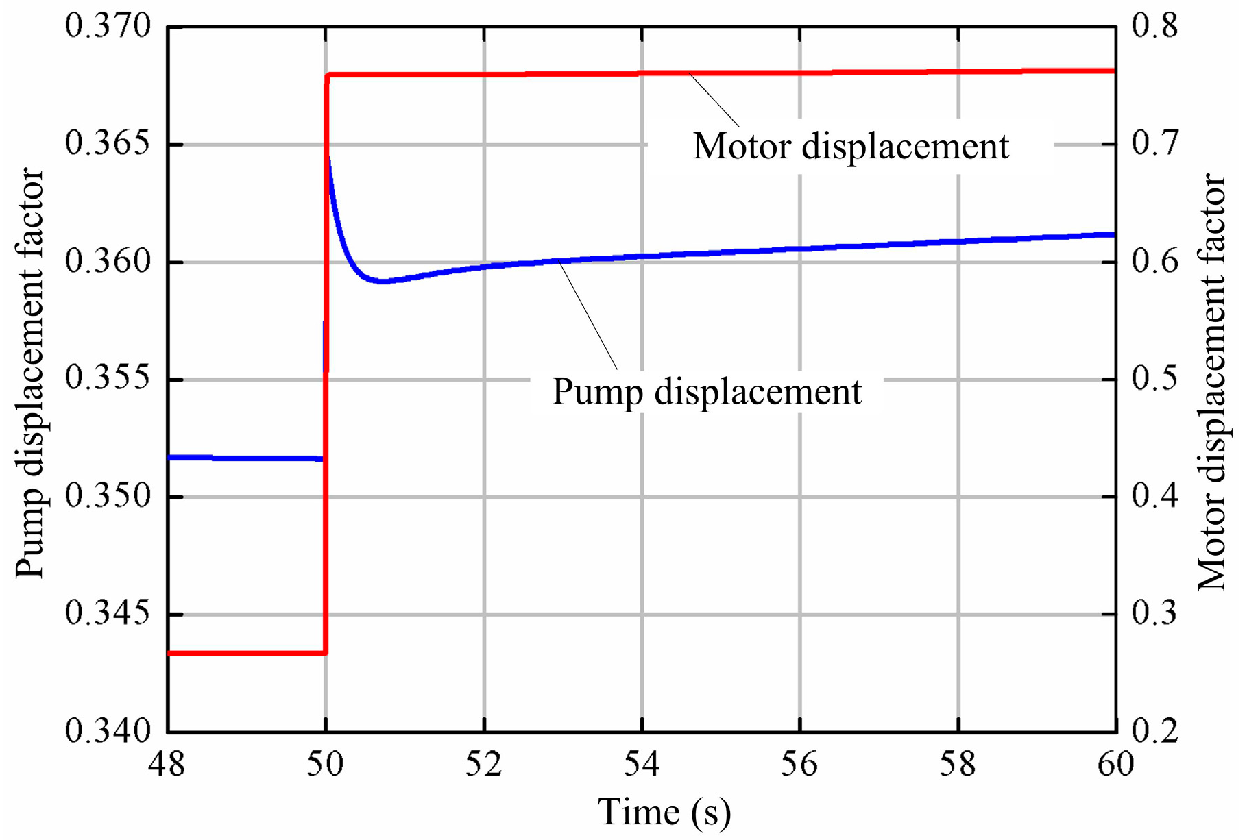
Figure 18.
Pump, accumulator, and motor flow rate.
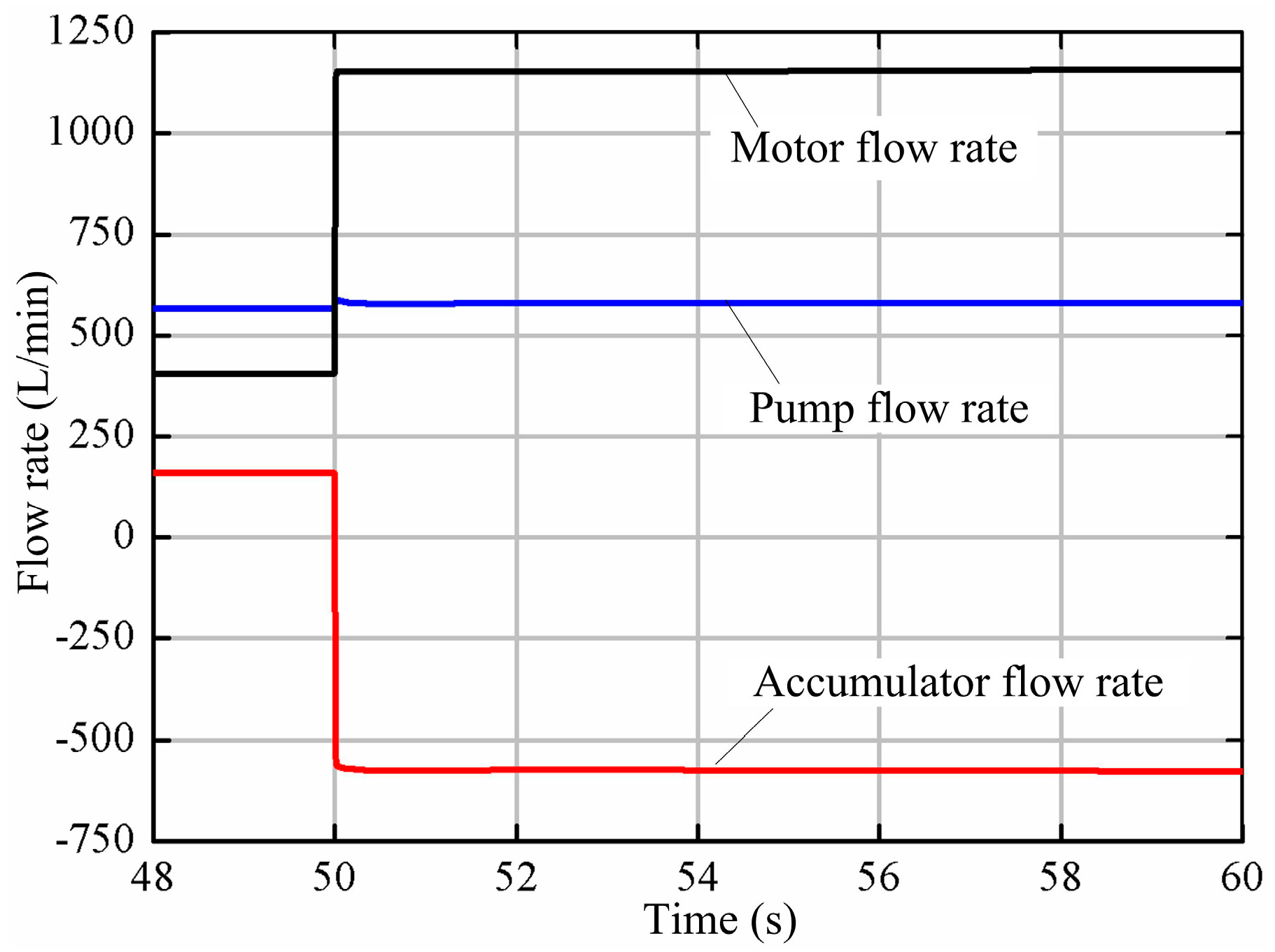
Figure 19.
Turbine, accumulator, and generator output power.
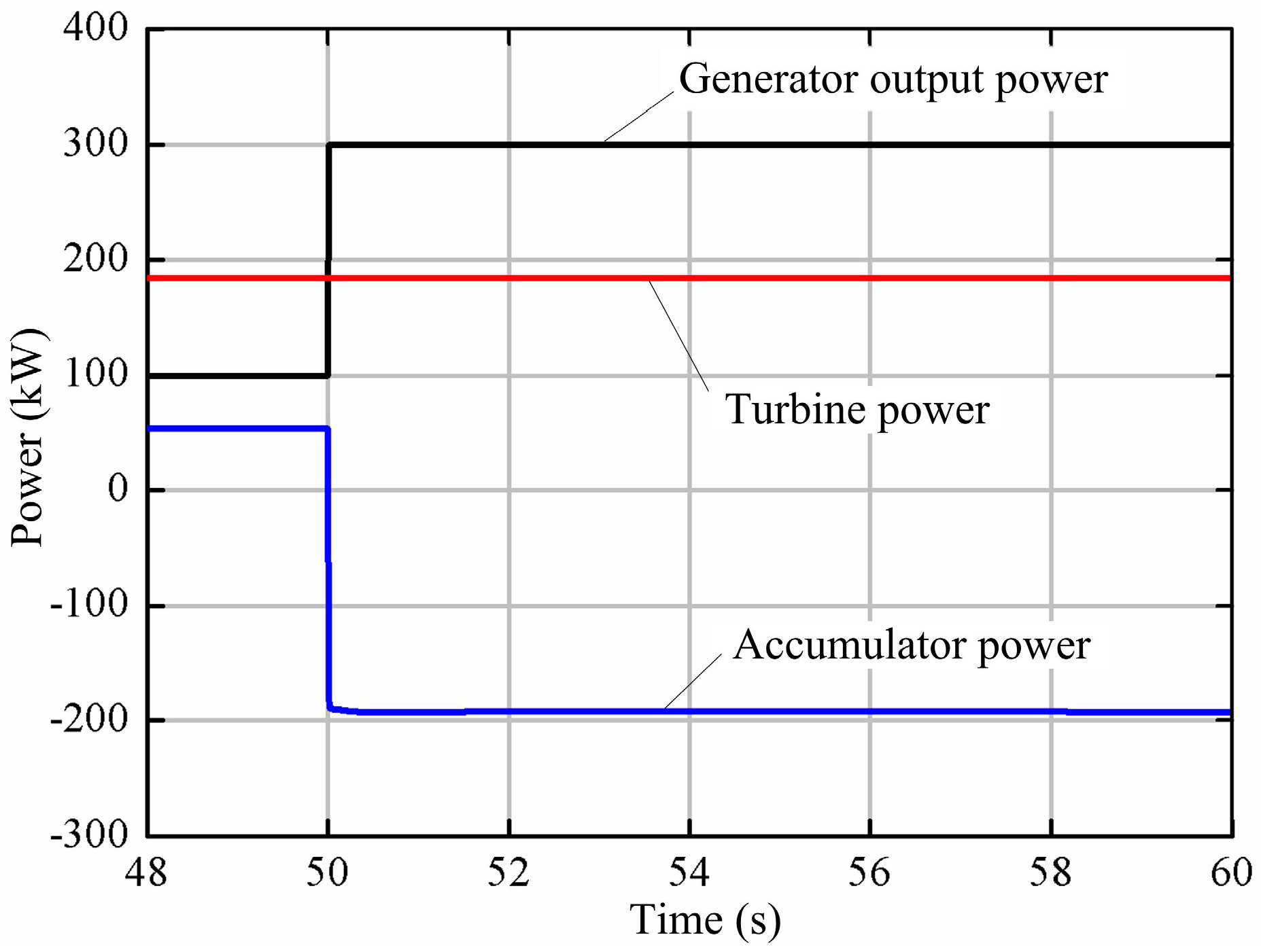
Figure 20.
Pump outlet, accumulator, and motor inlet pressure.
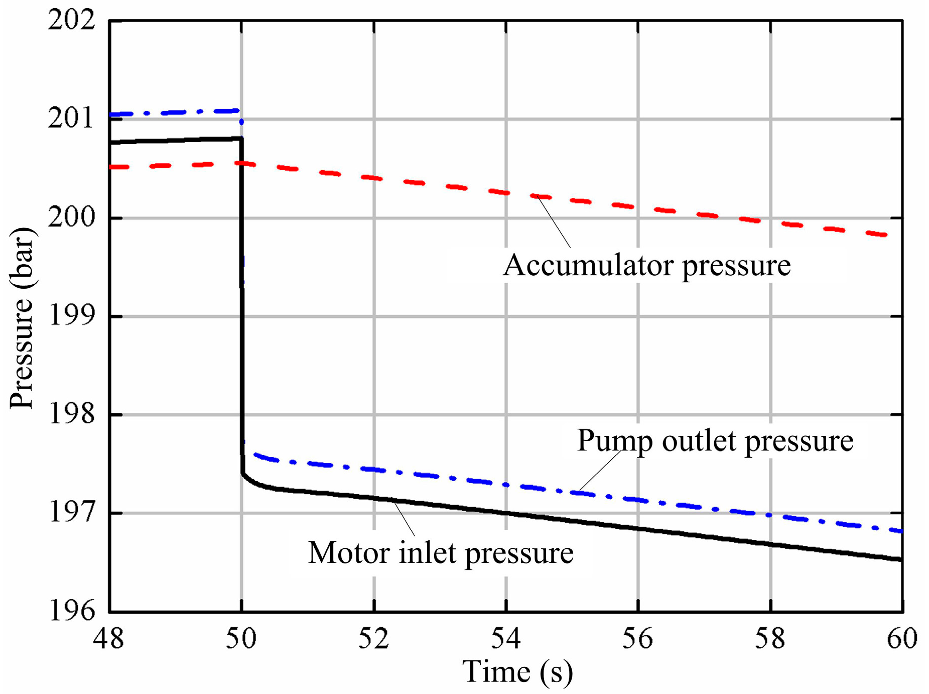
Figure 21.
Pump and motor speed.

Table 1.
Main parameters of wind turbine and hydraulic pump.
| Parameter | Symbol | Value | Unit |
|---|---|---|---|
| Rotor diameter | D | 43 | m |
| Swept area | A | 1453 | m2 |
| Hub height | H | 46 | m |
| Cut-in wind speed | Vin | 3.5 | m/s |
| Cut-out wind speed | Vout | 25 | m/s |
| Rated wind speed | Vrated | 15.5 | m/s |
| Rated power | Prated | 600 | kW |
| Maximum rotor speed | Rp | 27 | r/min |
| Pump maximum displacement | Vp | 67,000 | cm3/rev |
| Moment of inertia | Jp | 20,000 | kg·m2 |
| Coefficient of viscosity | Bp | 50 | Nm/(r/min) |
Table 2.
Main parameters of energy storage system.
| Parameter | Symbol | Value | Unit |
|---|---|---|---|
| Accumulator volume | V0 | 6000 | L |
| Gas precharge pressure | P0 | 120 | bar |
| Accumulator pressure | Pa | 210 | bar |
Table 3.
Main parameters of hydraulic motor and synchronous generator.
| Parameter | Symbol | Value | Unit |
|---|---|---|---|
| Motor maximum displacement | Vm | 500 | cm3/rev |
| Number of pole pairs | P | 2 | |
| Stator winding resistance | Ra | 0.006 | Ω |
| Synchronous speed | Rg | 1500 | r/min |
| Moment of inertia | Jm | 60 | kg·m2 |
| Coefficient of viscosity | Bm | 0.05 | Nm/(r/min) |
© 2018 by the authors. Licensee MDPI, Basel, Switzerland. This article is an open access article distributed under the terms and conditions of the Creative Commons Attribution (CC BY) license (http://creativecommons.org/licenses/by/4.0/).
Share and Cite
MDPI and ACS Style
Wei, L.; Liu, Z.; Zhao, Y.; Wang, G.; Tao, Y. Modeling and Control of a 600 kW Closed Hydraulic Wind Turbine with an Energy Storage System. Appl. Sci. 2018, 8, 1314. https://doi.org/10.3390/app8081314
AMA Style
Wei L, Liu Z, Zhao Y, Wang G, Tao Y. Modeling and Control of a 600 kW Closed Hydraulic Wind Turbine with an Energy Storage System. Applied Sciences. 2018; 8(8):1314. https://doi.org/10.3390/app8081314
Chicago/Turabian StyleWei, Liejiang, Zengguang Liu, Yuyang Zhao, Gang Wang, and Yanhua Tao. 2018. "Modeling and Control of a 600 kW Closed Hydraulic Wind Turbine with an Energy Storage System" Applied Sciences 8, no. 8: 1314. https://doi.org/10.3390/app8081314
Note that from the first issue of 2016, this journal uses article numbers instead of page numbers. See further details here.