Article

Coupled Vibration Analysis of Submerged Floating Tunnel System in Wave and Current

College of Civil Engineering and Architecture, Zhejiang University, Hangzhou 310058, China
*
Author to whom correspondence should be addressed.
Appl. Sci. 2018, 8(8), 1311; https://doi.org/10.3390/app8081311
Submission received: 11 July 2018 / Revised: 3 August 2018 / Accepted: 3 August 2018 / Published: 7 August 2018
(This article belongs to the Section Mechanical Engineering)

Abstract

:

Featured Application

A simplified theoretical model is proposed for vibration analysis of the coupled Submerged floating tunnel (SFT) tube-cable system under combined vortex-induced and wave forces. Several cases under different working conditions are presented to reveal the dynamic characteristics of the SFT. This approach can be extended to future actual structures to determine structural parameters and avoid strong resonance.

Abstract

Submerged floating tunnel (SFT) is an innovative underwater structure for crossing long straits, which withstands the effects of water wave and current throughout its lifecycle. This paper proposes a theoretical approach to investigate the nonlinear dynamic response of the SFT tube-cable system under combined parametric excitation and hydrodynamic forcing excitations (i.e., wave and vortex-induced loading). Firstly, the governing equations of the SFT system considering the coupled degrees of freedom in the tube and cable are established based on the Hamilton principle and are solved numerically. Then, several representative cases are analyzed to reveal the dynamic characteristics of the SFT. Finally, some key parameters are discussed, such as the wave and current conditions and the structural parameters. The results show that when the flow velocity reaches a certain value, the vortex-induced vibration (VIV) of the anchor-cables will excite a strong resonance in the structure. The displacement amplitude of the SFT increases with the increase of the wave height. Gravity-buoyance ratio (GBR) of the tube and the inclined mooring angle (IMA) of the cables jointly determine the natural vibration frequency of the SFT. The influence of the wave force on the tube is limited when the installation depth of SFT is more than 40 m.

Graphical Abstract

1. Introduction

Submerged floating tunnel (SFT) is a new concept with great potential for crossing long waterways and deep straits. A typical SFT consists of four major parts: (1) the tunnel tube, prefabricated on land and assembled underwater; (2) the revetment structures connecting the SFT tube and the mainland; (3) the mooring system to balance the residual buoyancy and limit the deformation of the tube; (4) the deep-water foundation installing the underwater cables [1,2,3].
During construction and operation, the SFT is located in a complex marine environment. In recent years, scholars have paid close attention to the dynamic behaviors of the SFT under hydrodynamic effects. Remseth et al. [4] proposed a finite element method considering the 3D flow field and the fluid-structure interaction according to the Navier-Stokes equation. The dynamic response of the SFT under water waves was studied in both the time and frequency domains. Paik et al. [5] developed a FE program to explore the dynamic response of SFT to wave loads, and presented the considerable effect of SFT location depth on the dynamic characteristics. Mazzolani et al. [6] in combination with the SFT conceptual design at Qiandao Lake in China, studied both the static and dynamic responses of the tunnel under environmental loads. The best performing cable configurations were also selected in view of a seismic analysis. Kunisu [7] used the boundary element method (BEM) and the Morison equation to calculate the wave load acting on the SFT. Long et al. [8,9] studied the effects of some basic structure parameters on the dynamic behaviors of the SFT under wave and current via ANSYS software. Seo et al. [10] measured the wave forces acting on the tunnel tube through a model test with scale SFT segments. A good agreement between the experimental results and the values predicted through the Morison equation was observed. Muhammad et al. [11] evaluated the static and dynamic responses of a SFT under hydrodynamic and seismic loadings.
Most of the above research mainly addressed the global performance of the SFT tube based on Morison equations [7,8,9,10,11]. However, despite that the support stiffness provided by anchor-cables acting on the tube was included in most of these models, the vibration of the cable itself was neglected.
Compared with the tunnel tube, oscillation of the SFT cables in fluid flow is more prone to occurring due to the periodic vortex shedding, known as vortex-induced vibration (VIV) [12]. Furthermore, because the top end of the anchor-cable is connected to the tube body, similar to other top-tensioned risers (TTR) in deep water platforms, the cables simultaneously encounter parametric excitations due to the time-varying tension which results from the motions of SFT tube under the environmental loads (such as regular waves) [13,14,15]. Hence, the local dynamic behavior of the cables is always a key problem in the design stage.
There is little research on SFT cable vibration undergoing parametric excitations and VIV. Sun and Su [16] used the Monte Carlo method to analyze the parametric vibration response of a simplified coupled tether-tube system subjected to random excitation. Wu et al. [17,18] developed an analytical model for analyzing marine cables of SFT under combined fluid loads and random seaquake excitations. Xiang and Chao [19] once performed a vibration analysis of the SFT system to evaluate the VIV of the cables, but the wave force on the tube body was not taken into account. Cantero et al. [20,21] analyzed the mooring cables’ stabilities under parametric excitations. They also studied the effects of parametric resonance on the tension forces of the vertical tethers in ABAQUS. Meanwhile, more research has been directed toward the dynamics of TTR under combined vortex and parametric excitations by means of FEM, semi-empirical models [13,14] and experimental investigations [15].
In these existing models for single marine risers, the upper floating platform has usually been regarded as a rigid body rather than a deformable one, and is represented as a pre-defined harmonic excitation. This means that these vortex-induced and parametric vibration prediction methods are not entirely applicable to the SFT cables.
From the above literature review, we can find that the tube or anchor-cables have usually been studied separately. While the tunnel is the main research object, the tunnel and cables are treated separately as a beam and linear springs, so the cable vibration is not excited. The other model focused on the motion of one single cable, regarding the tube as a mass block, which means the bending vibration of the tunnel is simplified. There are certain limitations in the existing theoretical or numerical models.
In essence, the global bending vibration of the SFT tube and the local oscillations of the cables are coupled with each other under realistic environmental conditions, which is supposed to be retained in the improved approach.
From this point onward, a theoretical model of the coupled SFT tube-cable system is established to more accurately describe the dynamic features of the SFT by considering the combined parametric and forcing excitations (i.e., the periodic vortex-induced and wave forces). The potential resonance phenomena are captured under the specified parameter settings, with a focus on the structural displacement and stress variation in the anchor-cable. Moreover, the influences of some factors, such as the hydraulic conditions and the structure parameters on the dynamic response are investigated to provide a reference for the structural design.

2. Modeling of the SFT System

2.1. Simplified SFT Model

Figure 1 shows a typical SFT system. A simplified mathematical model is also presented here to highlight the coupled-vibration effect between the SFT tube and the cables in ocean wave and current.
To simplify the calculation process, the SFT tube and cables are respectively regarded as a simply supported Euler-Bernoulli beam without torsional behaviors and standard tensional strings with constant parameters along their longitudinal directions. Material nonlinearity is not considered.
As the water wave attenuates rapidly with the depth of the water [5], the impact of waves on the cables can be discounted. Additionally, the vortex shedding frequency in the wake region around the tube is generally not close to the natural frequency of the tunnel. Additionally, because the vortex-induced force on the tunnel is much smaller than the wave loads and the restoring forces from the mooring system, in most cases aiming at the hydrodynamic response of SFT [6,8,9,11], only the wave forces on the tube are considered, without the vortex-induced force. Hence, we separately consider the wave force acting on the tube body, and the effect of water flow on the cables.
It has been proved that there is a phase difference equal to π/2 between the horizontal and the vertical wave loads, but with the same amplitudes [10,22]. For the tunnel tube, the cables play the role of elastic supports with a certain horizontal and vertical stiffness under the small deformation hypothesis [23,24]. This means that the vertical and horizontal vibrations of the tube are independent. Thus, the movement of the tube in the vertical direction is taken as an example and calculated in the subsequent sections.
In addition, much research has shown that the cross-flow (CF) vibration in marine risers is dominated by vortex-induced resonance [25,26]; hence, the cable in-line (IL) vibration is not taken into account in this study.
In Figure 1, D is the tube diameter; L is the tunnel length; x = xti is the location of the i# cable (i = 1, 2, …, n) along the X direction; li is the cable length; αi is the inclined angle of the cable; hi is the cable spacing; Xi, Yi are the local axes to describe the motion of cables; vi(xi, t) is the displacement of the i# cable in cross-flow direction; z(x, t) is the vertical displacement of the tube; wy, wz are the horizontal and vertical velocities of the wave particles at the center of the tube, respectively.

2.2. Governing Equations

Based on the previous simplified model and the corresponding assumptions [5,10,26], the governing equations of the two motion components (i.e., tube vertical displacement and cable cross-flow vibration) of the SFT system in wave and current are established by using the Hamilton principle [27].
{ m c i 2 v i t 2 + c i v i t ( T i + Δ T i ) 2 v i x i 2 = F i L F i D E t I t 4 z x 4 + m t 2 z t 2 + c t z t + 2 i = 1 n Δ T i sin α i δ ( x x i ) = F t W
where mci is the mass per unit length of the i# cables in air; mt is the mass per unit length of the tube in air; EtIt is the bending stiffness of the tube around the Y axis; ci, ct are the damping coefficients of the cables and tube; Ti is the initial tension force of the i# cable; ΔTi is the dynamic tension variation in the cable; FiL is the vortex-induced lift force on the cable; FiD is the drag force on the cable; FtW is the vertical wave force acting on the tube; δ is the Dirac function.
In Equation (1), ΔTi reflects the coupled two DOFs motions of the tube-cable system, and comes from the VIV of itself and the vertical motion of the tube. It can be calculated as [28]:
Δ T i = E c i A c i l i 0 l i ε i d x i = E c i A c i l i [ z ( x = x t i ) s i n α i + 0 l i 1 2 ( v i x i ) 2 d x i ]
where Eci is the elastic modulus of the i# cables; Aci is the sectional area of the i# cables; εi is the cable axial strain; z(x = xti) is the vertical displacement of the tube at the position of the i# cables.

2.3. Hydrodynamic Forces on SFT

It has been realized that the periodic vortex shedding in the near wake of the cable induces the oscillating lift and drag forces. The lift forces on the i# pair of cables in the CF direction and the vortex-shedding frequency are respectively given as [29,30]:
F i L = 1 2 ρ w d i C L ( v 0 sin α i ) 2 cos ( 2 π f v i t + θ i )
f v i = St v 0 d i
where ρw is the fluid density; St is the Strouhal number, and St = 0.2, here [30]; di is the diameter of the cable; CL is the lift force coefficient, and CL = 0.7 [19]; v0 is the uniform flow velocity; θi is arbitrary phase angle, and θi = 0 here.
The added mass and drag force on the i# anchor-cables in the CF direction and the wave force acting on the tube in the Z direction are expressed via Morison’s equation [10]:
F i D = 1 4 π d i 2 ρ w C m i v ¨ i + 1 2 ρ w d i C D i v ˙ i | v ˙ i |
F t W = 1 4 π D 2 ρ w w ˙ z + 1 4 π D 2 ρ w C m ( w ˙ z z ¨ ) + 1 2 ρ w D C D ( w z z ˙ ) | w z z ˙ |
where Cm and Cmi are the added mass coefficients, taken as 1.0 [24]; CD and CDi are the drag force coefficients, equal to 0.65 here [10].
According to the linear wave theory, wz is defined as [10]:
w z = π H T ( sinh k ( z 0 + d ) sinh k d ) sin ω w t
in which H is the wave height; T is the wave period; k is the wave number; ωw is the angular frequency (ωw = 2π/T); z0 is the installation depth of the center line of SFT tube; d is the water depth.

2.4. Solution of Equations

In line with the references [18,31], we assume that the parameter excitations on anchor-cables mainly come from the tension variations in cables, rather than the displacements of the upper end connected to the tube. This is reasonable when the displacement of the tube is much smaller than the length of cables, because of the strong stiffness of the mooring system and the length of the tethers, which reach up to 200 m or even longer.
In terms of the mode superposition method, the displacements of the structure can be approximately expressed in standard forms as follows [18,31]:
{ v i ( x i ,   t ) = m i v i ( t ) sin ( m i π x i l i ) m i = 1 ,   2 ,   3 z ( x ,   t ) = m z ( t ) sin ( m π x L ) m = 1 ,   2 ,   3
where vi(t) and z(t) are the generalized coordinates, sin(miπxi/li) and sin(mπx/L) are the shape functions.
Seo et al. [32] pointed out that the first-order vibration of the SFT tube contributes the most to the displacement response. Tagata [33] concluded that the first-order mode dominates when external excitation is applied at the end of the cable. Hence, in this article, we deal with the fundamental mode vibration, and then take m = mi = 1.
Substituting Equation (8) into Equation (1), we get:
v ¨ i + [ ω i 1 2 + E c i A c i π 2 m ¯ c i l i 3 z sin ( π x t i L ) sin α i ] v i + 2 ξ i 1 ω i 1 v ˙ i + E c i A c i π 4 4 m ¯ c i l i 4 v i 3 = 2 m ¯ c i π ρ w d i C L i v 0 2 cos ( 2 π f i t ) 4 3 m ¯ c i π ρ w d i C D i v ˙ i | v ˙ i |         i = 1 ,   2 ,   ,   n z ¨ + { ω ¯ t 1 2 + 2 i n [ 2 m ¯ t L E c i A c i l i sin α i sin 2 ( x t i π L ) ] } z + 2 ξ t 1 ω t 1 z ˙ = 2 i n 2 m ¯ t L [ E c i A c i π 2 4 l i 2 v i 2 ] sin ( x t i π L ) sin α i + 1 m ¯ t L π D 2 ρ w ( 1 + C m ) w ˙ z D w ( t ) m ¯ t L  
where ωi1 is the first-order natural frequency of the i# pair of cables, ω i 1 = [ ( π / l i ) 2 T 0 / m ¯ c i ] 1 / 2 , m ¯ c i = m c i + ( π d i 2 / 4 ) ρ w C m i ; ξi1 is the first-order damping ratio of the i# cables; ω ¯ t 1 is the fundamental frequency of the tube without the cables, ω ¯ t 1 = [ E t I t ( π / L ) 4 / m ¯ t ] 1 / 2 , m ¯ t = m t + ( π D 2 / 4 ) ρ w C m ; ξt1 is the first-order damping ratio of the tube; Dw(t) is the item associated with the hydraulic resistance on the tube, and can be computed as: D w ( t ) = 1 2 ρ w D C D 0 L ( w z z ˙ sin π x L ) | w z z ˙ sin π x L | sin ( π x L ) d x .
It can be found in Equation (9) that the motions of the cables and tube are coupled to each other, forming an autoparametric vibration system. Additionally, the tube-cable system is also subjected to the external hydrodynamic forcing excitations (i.e., vortex-induced force on the cables, and wave force on the tube). This better reflects the nonlinear vibration characteristics of the SFT system in a marine environment. The fourth-order Runge-Kutta method is adopted to solve Equation (9) within MATLAB software with a calculation step length of 0.01 s to guarantee the convergence of the integration method [24].

3. Case Study

3.1. Parameter Values in the Numerical Model

There are no practical engineering applications of SFTs around the world. Some basic parameters of the structure and the fluid loads for the case study are selected in line with references [22,34].
In order to obtain the resonance performance of the tube-cable system, the dimensions of the structures are artificially adjusted in accordance with the following certain conditions:
(1)
The first-order vibration frequency of the SFT tube is twice the fundamental frequency of the i# cables (i.e., ωt1:ωi1 = 2:1), which leads to the principal parametric resonance [18,21];
(2)
When the vortex-induced frequency is assumed to be consistent with the cable frequency (i.e., 2πfvi = ωi1), significant VIV of the cables occurs [13,30]. After the determination of ωi1 = 3.493 rad/s in Equation (9), the flow velocity v0 = 1.18 m/s can be further calculated by Equation (4).
It is also worth noting that, after the anchor-cables are connected to the tube body, the taut cables play the role of elastic supports. Sato et al. [23] concluded that, if the support stiffness provided by the cables and the bending rigidity of the tube meet a certain condition (Equation (10)), the natural frequency of the tube is increased, but the same vibration mode is retained as in the tube without the cables.
k i h 4 24 E t I t 0.05  
where ki = EciAci/li, is the stiffness of the anchor cables; h is the cable interval.
Figure 2 gives the detailed process to obtain the basic parameters in this case study (some essential parameters in the “dashed box” in Figure 2 are selected from the above references [22,34]).
Eventually, the total length of SFT L is equal to 150 m, and 2 pairs of cables with identical parameters are symmetrically installed in the L/3 and 2 L/3 positions. The particular values of the SFT parameters are given in Table 1.

3.2. Analysis Results

To better understand the vibration status of the SFT system, the time history of the structure components for several representative cases are presented in this section. In particular, the resonance characteristics of the tube-cable system, the coupling effects on the cables and the influence of wave force are explored.
In this case study, the maximum deformation occurs at the mid-span of the cables and tube. Therefore, the mid-span displacements of SFT components are considered first. Meanwhile, the stress variations in the anchor-cables are also presented.

3.2.1. Amplification under Combined Parametric and Hydrodynamic Exactions

Figure 3a depicts the vibration curves of the SFT system under combined parametric excitation and external hydraulic loads. After the steady vibration state is reached, the mid-span amplitude of the cables is about 0.402 m. In addition, the time-history curves of tube displacement and cable stress variation exhibit similar trends, which indicates that the tension fluctuation of the cables is mainly affected by the motion of the tube.
As the wave force acting on the tube shows a logarithmic attenuation with the increases of the installation depth of the tube [22], Figure 3b also gives the vibration responses of the system without wave force. Comparing Figure 3a with Figure 3b, it can be found that the VIV of the cables drives the SFT system into a stable resonance status. However, since the wave period (10.8 s) is much longer than the natural vibration period of the tube (0.899 s), the influence of wave force on the system is very limited. The results are listed in Table 2.

3.2.2. Auto-Parametric Resonance of the System without Damping

In order to more directly reflect the coupling effect between the cables and the tube, Figure 4 gives the displacement time history curves of these structural components, in the case of undamped parametric vibration without hydrodynamic effects. The kinetic energy of the system is transferred among the cables and the tube, an obvious “beating” phenomenon of the system during parametric resonance is observed.
The initial displacements of the cable and the tube are set as 0.010 m and 0.050 m, respectively, but the maximum amplitude of the cable reaches 0.949 m. This is significantly greater than the initial state. As the mass of the cable is much smaller than the tube, the cable is more prone to severely oscillating.
It should be noted that in this working condition, Equation (9) is simplified into the same form reported in the existing references [16,35], where the tube was modeled as a spring-mass lump with one degree of freedom, rather than a slender beam. This means that the previous model is a special case of this tube-cable system. More importantly, it also proves the reliability and the superiority of the proposed model in this paper.

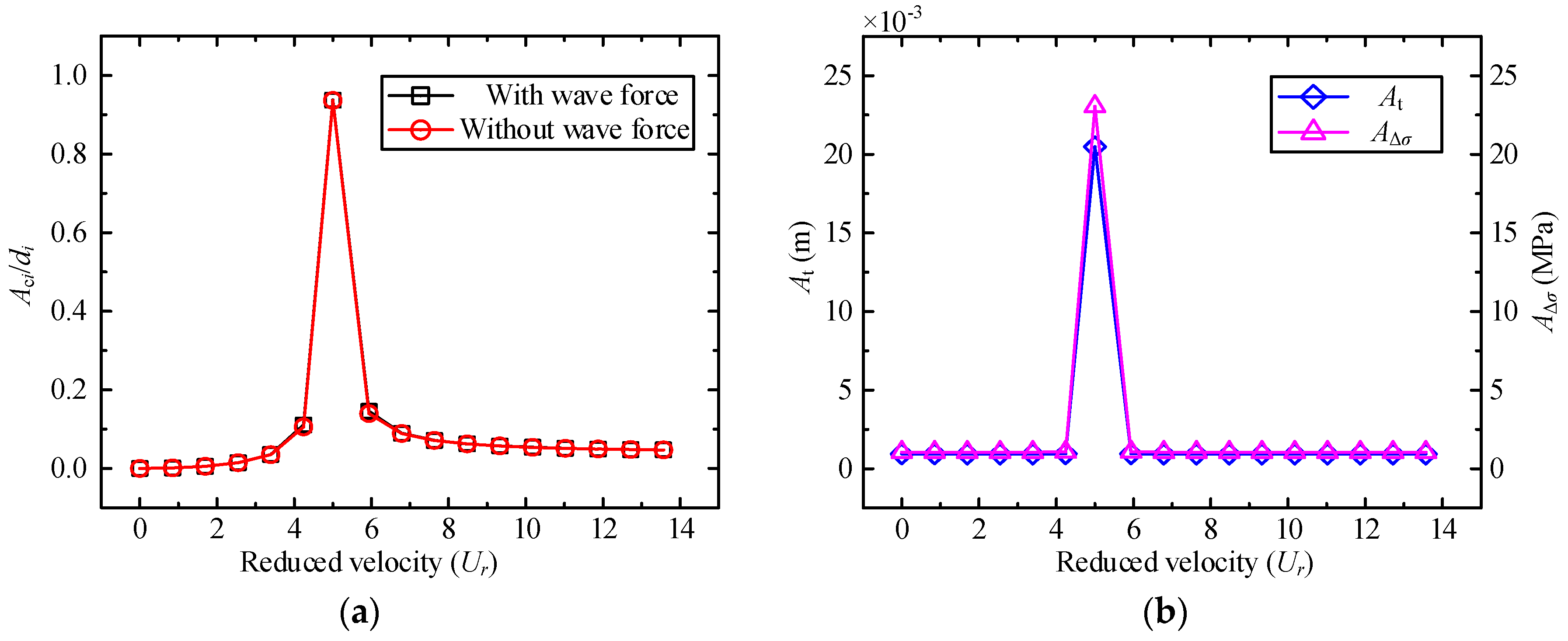
3.2.3. VIV of the Cable without the Coupling Effect

To further study the coupling effects of the tube-cable system on the anchor-cables, Figure 5 shows the VIV time-dependent curve of the cables without considering the coupling effect. Compared with Figure 3, it can be found from Figure 5 that the steady-state amplitude increases from 0.402 m to 0.688 m with a relative difference of 66.17%. However, the amplitude of Δσ sharply decreases from 22.061 Mpa to 0.058 Mpa. The results are given in Table 3.
This also demonstrates that the motion of the tube plays a leading role in the tension variation of the cable. To a certain extent, the coupling effect inhibits the lateral vibration of the cable. The VIV of the cables should be minimized from the angles of the optimum parameter design and construction measures.

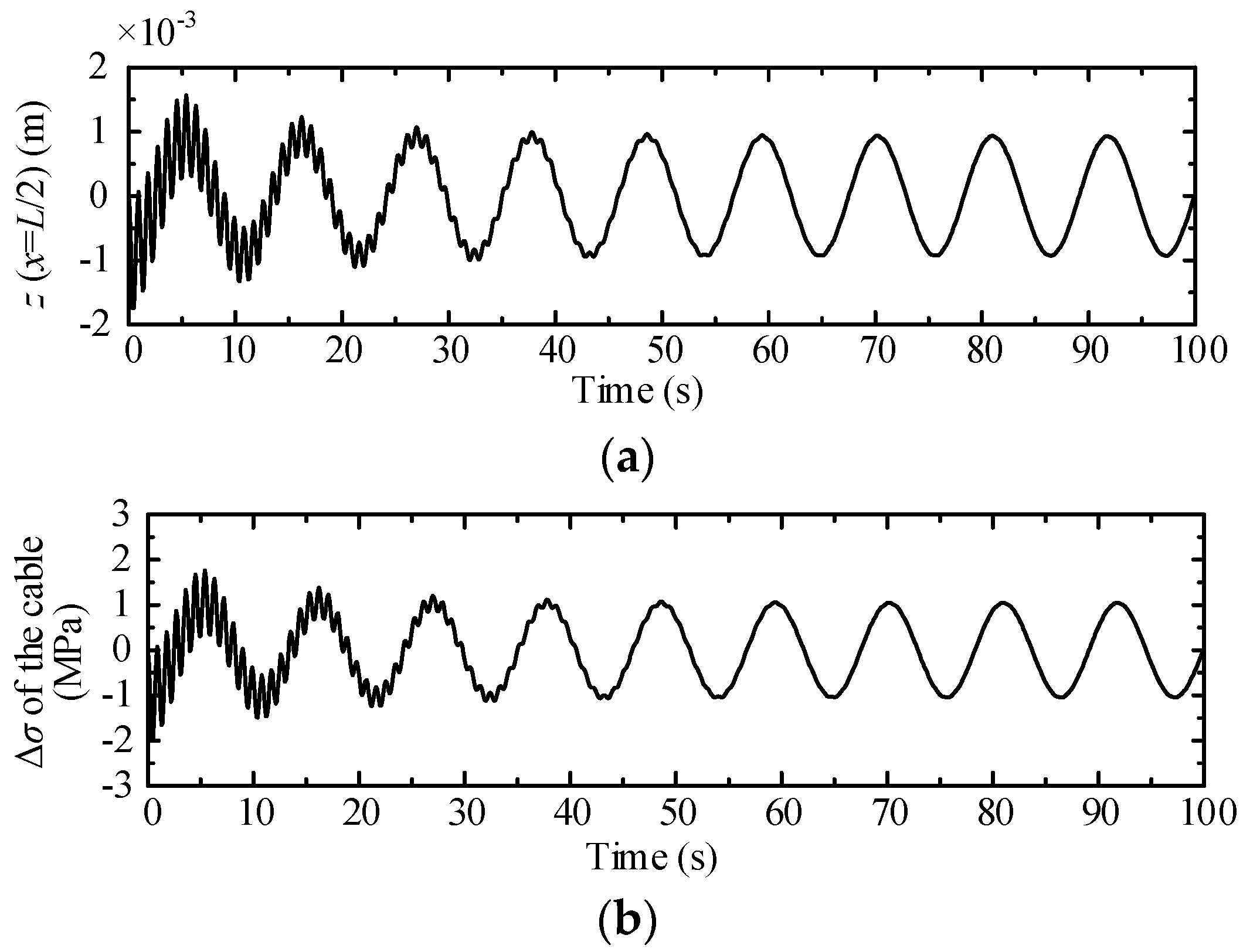
3.2.4. Structural Response under Single Wave Force

The time history response of the SFT due to the single action of wave force is shown in Figure 6. The steady-state amplitude of the tube is less than 1 mm, and the amplitude of Δσ equals about 1.03 Mpa. The underwater installation depth of the SFT is generally more than 30 m in order to meet the navigation requirements on the water surface [1,2]. Because water particles in the wave field attenuate rapidly with water depth, other than under extreme wave conditions, the wave forces have little impact on the SFT.

4. Parametric Influence Study

The following subsections evaluate the influence of the main design variables faced in an actual project, including the fluid conditions and fundamental structure parameters. Parametric studies are carried out based on the coupled tube-cable system with different working conditions given in Section 3.2.

4.1. Effect of Current Velocity

Figure 7 shows the structural dynamic response under different current velocities, with the same working conditions as given in Figure 3. The reduced velocity Ur is defined as: Ur = v0/fidi; Aci/di is introduced as the dimensionless maximum amplitude of the cable at its mid-section; At is the maximum vibration amplitude of the tube at its mid span; AΔσ is the maximum stress variation in the cables.
In Figure 7a, the largest amplitude of the cable occurs when Ur = 5.00(flow velocity v0 = 1.18 m/s), which illustrates a notable resonance phenomenon, called as lock-in. The VIV suppression measures should be given enough attention in the stages of design. However, the wave force acting on the SFT tube has a finite influence on the anchor cables.
As shown in Figure 7b, in the case that the current velocity is far away from the lock-in region, the calculation results are similar to those shown in Figure 6, which means the current effect is weak. Further comparing Figure 7a with Figure 7b, the lower inertia of the cables than of the tube will lead to a wider flow velocity range, which can excite intensive vibrations of the cables.

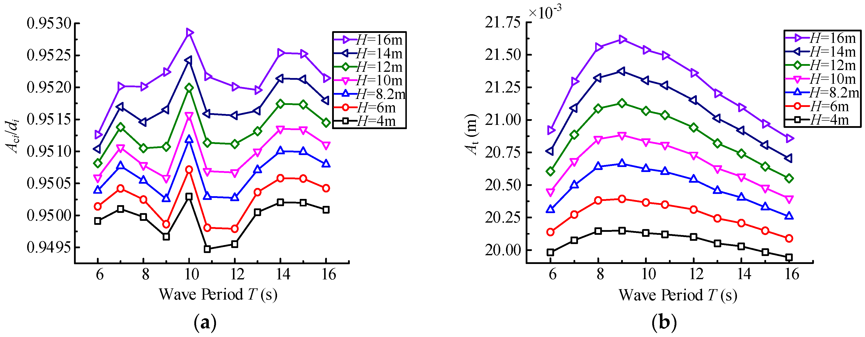
4.2. Effect of Wave Parameters

Figure 8 gives the SFT maximum amplitude response when the wave period T varies from 6 to 16 s and the wave height H varies from 4 to 16 m [36], under the same working conditions given in Figure 3a. As illustrated in Figure 8, in general, the structural response increases with the increase in wave height, but the effect of the wave period is more complicated.
In Figure 8a, the maximum value of Aci/di (the normalized maximum amplitude of the cable) is obtained at T ≈ 10 s. However, since the performance of the anchor cable is mainly dominated by the vortex-induced forces, the change in the vibration amplitude is negligible.
It can be seen from Figure 8b that, with the increase of the wave period, the amplitude of the tube At first shows a rising trend, and then a decreasing trend, which is consistent with the “wave loads vs. wave numbers” curves in references [7,10]. Also, At reaches a maximum at T ≈ 9 s. This is because, in Equations (6) and (7), the amplitude and frequency of the wave force on the SFT tube are functions of the wave period, so that the structure response may exist at extreme points as the wave period changes.

4.3. Effect of Fundamental Structural Parameters

The gravity-buoyance ratio (GBR) of the tube and the inclined mooring angle (IMA) of the anchor cables are key parameters affecting the structural stability of the SFT [35]. GBR affects the initial tension of the cables; meanwhile, the variation in IMA in turn causes a change of the cables’ supporting stiffness on the tube, which jointly determines the natural vibration frequency of the components and further influence the autoparametric vibration of the SFT system.
In Figure 9, we discuss the influence of GBR/IMA settings on the maximum displacement amplitude of the cables, for the same case given in Figure 4 (undamped parametric vibration of the system without fluid effects).
Under the parameter settings in Table 1 (i.e., GBR = 0.65, IMA = 90°/ωt1:ωi1 = 2:1), the principal autoparametric resonance occurs and the lateral dis. amplitude of the cable reaches its maximum. This is an extreme situation and should be avoided in engineering practice.
Once GBR ≥ 0.7, the parametric vibration of the system will not cause large deformation of the anchor cables. However, when GBR < 0.7, if IMA meets certain conditions, an intensive vibration of the anchor cables can still be excited. This indicates that the parametric vibration of system is more sensitive to GBR, which should be given priority in the design process.
The IMA should take into consideration the support stiffness and the construction of the underwater foundation, thus 45° is determined as a reasonable value.

4.4. Effect of Tube Installation Depth

It can be seen from Figure 10 (the same working condition as Figure 3a) that the amplitude of the cables and the tube decreases with the increase of the tube installation depth, which is consistent with the results in [5]. While the installation depth is within the range of 5~40 m, the amplitude reduction rate of the cable is greater than that of the tube. Instead, once the buried depth is more than 40 m, the amplitude of the tube will decrease more prominently. The underwater installation depth of SFT should be decided in combination with the requirements for water surface navigation, wave conditions and construction difficulties.

5. Conclusions

This paper analyzes the dynamic response of SFT subjected to the external hydrodynamic loads using a theoretical approach. The proposed model focuses on the coupled tube-cable system rather than a separate marine tether or a slender tube on elastic supports. In comparison with the existing methods, it is thus more in line with the actual characteristics of the SFT and help us better understand the vibration mechanism. The significant resonance phenomena of the system are obtained under artificial parameter settings. Also, several cases with different working conditions are presented to describe the vibration characteristics and prove the correctness of this model. Although only the vertical vibrations of the tube are demonstrated in the case study, the proposed procedure can be extended to the actual structure, with more complex dynamic behaviors. Furthermore, parametric studies are performed to provide some references for engineering practice. From this research, the main conclusions can be summarized as follows:
(1)
When the fundamental frequency of the cables reaches one-half that of the tube (i.e., ωt1:ωi1 = 2:1), the autoparametric resonance of the SFT system is significant, which is more adverse to the cable.
(2)
VIV of the anchor-cables can excite the resonance of the tube-cable system. Although the coupling effect of the system suppresses the lateral displacement of the cables to some degree, the VIV of the cables may stimulate the vibration of the tube body, which leads to a significant tension variation in the cables.
(3)
The displacement amplitude of SFT is very sensitive to the change of the uniform flow velocity. When the flow velocity v0 = 1.18 m/s (reduced velocity Ur = 5.00), the displacement amplitude of the cables reaches its maximum.
(4)
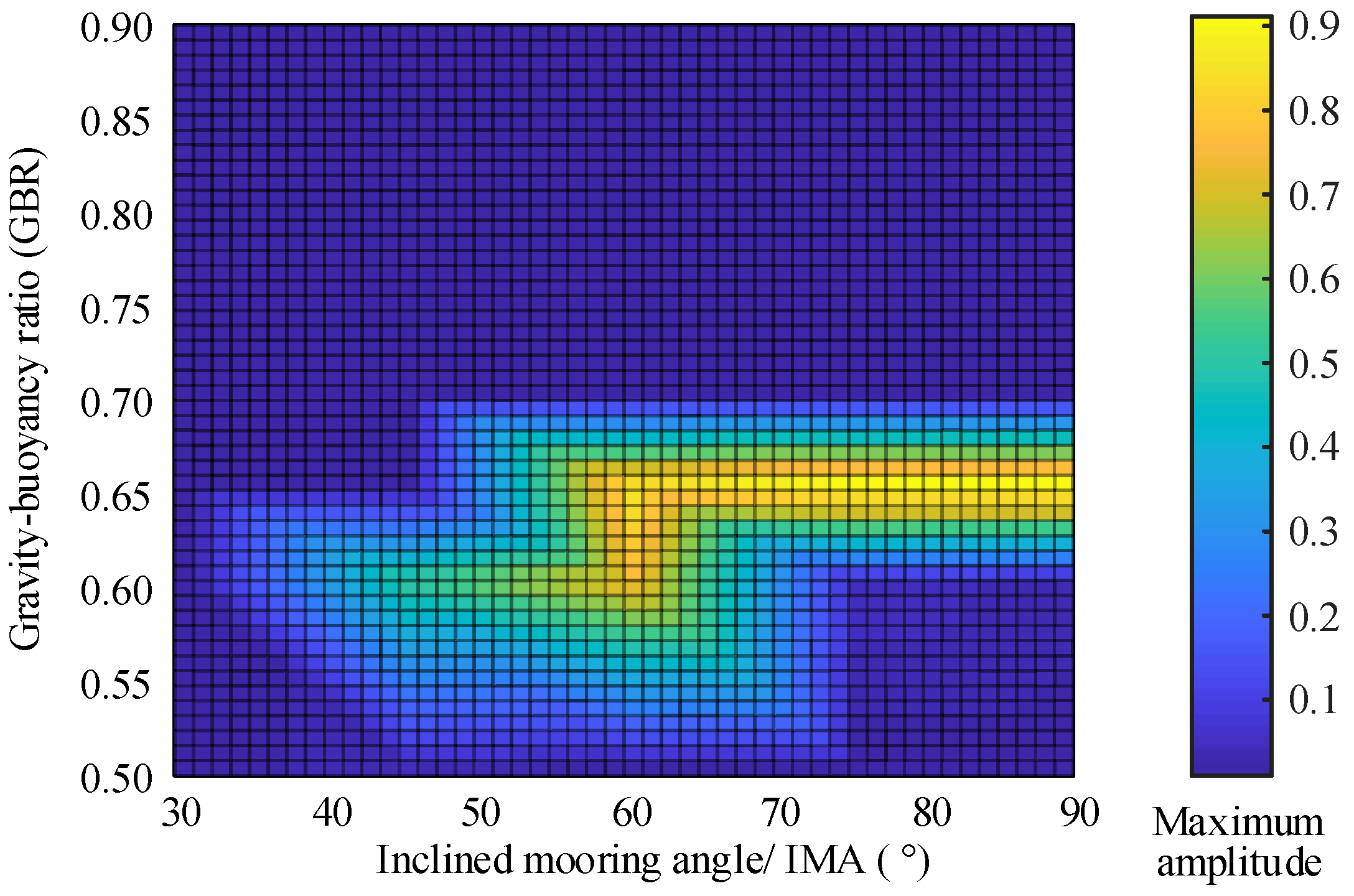
Vibration frequency of the tube and cable is simultaneously decided by GBR and IMA. The parametric vibration of the system is more sensitive to the changes in GBR. Based on the case study, IMA is recommended at around 45°, and a reasonable GBR should be greater than 0.7.
(5)
The displacement of the structure increases with the increase in the wave height. The amplitude of the tube is maximized when the wave period is about 9 s. Meanwhile, in the practical engineering, we can reduce the impact of the wave force by properly increasing the underwater installation depth of the SFT.

Author Contributions

Y.X. guided the research. The manuscript was written by Z.C. and confirmed by all the authors.

Funding

This work was financially supported by the (National Natural Science Foundation of China) grant numbers (51541810) and (51279178).

Conflicts of Interest

The authors declare no conflict of interest.

References

  1. Østlid, H. When is SFT competitive? Procedia Eng. 2010, 4, 3–11. [Google Scholar] [CrossRef]
  2. Xiang, Y.; Yang, Y. Challenge in Design and Construction of Submerged Floating Tunnel and State-of-art. Procedia Eng. 2016, 166, 53–60. [Google Scholar] [CrossRef]
  3. Martinelli, L.; Domaneschi, M.; Shi, C. Submerged Floating Tunnels under Seismic Motion: Vibration Mitigation and Seaquake effects. Procedia Eng. 2016, 166, 229–246. [Google Scholar] [CrossRef]
  4. Remseth, S.; Leira, B.J.; Okstad, K.M.; Mathisen, K.M.; Haukås, T. Dynamic response and fluid/structure interaction of submerged floating tunnels. Comput. Struct. 1999, 72, 659–685. [Google Scholar] [CrossRef]
  5. Paik, I.Y.; Oh, C.K.; Kwon, J.S.; Chang, S.P. Analysis of wave force induced dynamic response of submerged floating tunnel. KSCE J. Civ. Eng. 2004, 8, 543–550. [Google Scholar] [CrossRef]
  6. Mazzolani, F.M.; Landolfo, R.; Faggiano, B.; Esposto, M.; Perotti, F.; Barbella, G. Structural Analyses of the Submerged Floating Tunnel Prototype in Qiandao Lake (PR of China). Adv. Struct. Eng. 2008, 11, 439–454. [Google Scholar] [CrossRef]
  7. Kunisu, H. Evaluation of wave force acting on Submerged Floating Tunnels. Procedia Eng. 2010, 4, 99–105. [Google Scholar] [CrossRef]
  8. Long, X.; Ge, F.; Wang, L.; Hong, Y. Effects of fundamental structure parameters on dynamic responses of submerged floating tunnel under hydrodynamic loads. Acta Mech. Sin. 2009, 25, 335–344. [Google Scholar] [CrossRef]
  9. Long, X.; Ge, F.; Hong, Y. Feasibility study on buoyancy–weight ratios of a submerged floating tunnel prototype subjected to hydrodynamic loads. Acta Mech. Sin. 2015, 31, 750–761. [Google Scholar] [CrossRef] [Green Version]
  10. Seo, S.; Mun, H.; Lee, J.; Kim, J. Simplified analysis for estimation of the behavior of a submerged floating tunnel in waves and experimental verification. Mar. Struct. 2015, 44, 142–158. [Google Scholar] [CrossRef]
  11. Muhammad, N.; Ullah, Z.; Choi, D.-H. Performance Evaluation of Submerged Floating Tunnel Subjected to Hydrodynamic and Seismic Excitations. Appl. Sci. 2017, 7, 1122. [Google Scholar] [CrossRef]
  12. Blevins, R.D. Flow-Induced Vibration, 2nd ed.; Van Nostrand Reinhold Co.: New York, NY, USA, 1990. [Google Scholar]
  13. Chen, W.; Li, M.; Guo, S.; Gan, K. Dynamic analysis of coupling between floating top-end heave and riser’s vortex-induced vibration by using finite element simulations. Appl. Ocean Res. 2014, 48, 1–9. [Google Scholar] [CrossRef]
  14. Yuan, Y.; Xue, H.; Tang, W. A numerical investigation of Vortex-Induced Vibration response characteristics for long flexible cylinders with time-varying axial tension. J. Fluids Struct. 2018, 77, 36–57. [Google Scholar] [CrossRef]
  15. Franzini, G.R.; Pesce, C.P.; Salles, R.; Gonçalves, R.T.; Fujarra, A.L.C.; Mendes, P. Experimental Analysis of a Vertical and Flexible Cylinder in Water: Response to Top Motion Excitation and Parametric Resonance. J. Vib. Acoust. 2015, 137, 031010. [Google Scholar] [CrossRef]
  16. Sun, S.; Su, Z. Parametric vibration of submerged floating tunnel tether under random excitation. China Ocean Eng. 2011, 25, 349–356. [Google Scholar] [CrossRef]
  17. Wu, Z.; Mei, G. Dynamic Response Analysis of Cable of Submerged Floating Tunnel under Hydrodynamic Force and Earthquake. Shock Vib. 2017, 2017, 3670769. [Google Scholar] [CrossRef]
  18. Wu, Z.; Ni, P.; Mei, G. Vibration response of cable for submerged floating tunnel under simultaneous hydrodynamic force and earthquake excitations. Adv. Struct. Eng. 2018. [Google Scholar] [CrossRef]
  19. Xiang, Y.; Chao, C. Vortex-Induced Dynamic Response Analysis for the Submerged Floating Tunnel System under the Effect of Currents. J. Waterw. Port Coastal Ocean Eng. 2013, 139, 183–189. [Google Scholar]
  20. Cantero, D.; Rønnquist, A.; Naess, A. Recent Studies of Parametrically Excited Mooring Cables for Submerged Floating Tunnels. Procedia Eng. 2016, 166, 99–106. [Google Scholar] [CrossRef]
  21. Cantero, D.; Rønnquist, A.; Naess, A. Tension during parametric excitation in submerged vertical taut tethers. Appl. Ocean Res. 2017, 65, 279–289. [Google Scholar] [CrossRef]
  22. Xiang, Y.; Zhang, K. The layered integrating method for calculating wave force of submerged floating tunnel based on Morison equation. J. Zhejiang Univ. Eng. Sci. 2011, 45, 1399–1404. [Google Scholar]
  23. Sato, M.; Kanie, S.; Mikami, T. Mathematical analogy of a beam on elastic supports as a beam on elastic foundation. Appl. Math. Model. 2008, 32, 688–699. [Google Scholar] [CrossRef]
  24. Xiang, Y.; Chen, Z.; Yang, Y.; Lin, H.; Zhu, S. Dynamic response analysis for submerged floating tunnel with anchor-cables subjected to sudden cable breakage. Mar. Struct. 2018, 59, 179–191. [Google Scholar] [CrossRef]
  25. Williamson, C.H.K.; Govardhan, R. A brief review of recent results in vortex-induced vibrations. J. Wind Eng. Ind. Aerodyn. 2008, 96, 713–735. [Google Scholar] [CrossRef]
  26. Wu, X.; Ge, F.; Hong, Y. A review of recent studies on vortex-induced vibrations of long slender cylinders. J. Fluids Struct. 2012, 28, 292–308. [Google Scholar] [CrossRef]
  27. Clough, R.W.; Penzien, J.; Griffin, D.S. Dynamics of Structures, 2nd ed.; McGraw-Hill: New York, NY, USA, 1993. [Google Scholar]
  28. Zhang, M.; Fu, S.; Song, L.; Tang, X.; He, Y. A time domain prediction method for the vortex-induced vibrations of a flexible riser. Mar. Struct. 2018, 59, 458–481. [Google Scholar] [CrossRef]
  29. Gopalkrishnan, R. Vortex-Induced Forces on Oscillating Bluff Cylinders. Ph.D. Thesis, MIT, Cambridge, MA, USA, 1993. [Google Scholar]
  30. Kaneko, S.; Nakamura, T.; Inada, F. Flow-Induced Vibrations: Classifications and Lessons from Practical Experiences, 2nd ed.; Academic Press: Oxford, UK, 2013. [Google Scholar]
  31. Su, Z.; Sun, S. Seismic response of submerged floating tunnel tether. China Ocean Eng. 2013, 27, 43–50. [Google Scholar] [CrossRef]
  32. Seo, S.; Sagong, M.; Son, S. Global response of submerged floating tunnel against underwater explosion. KSCE J. Civ. Eng. 2015, 19, 2029–2034. [Google Scholar] [CrossRef]
  33. Tagata, G. Harmonically forced, finite amplitude vibration of a string. J. Sound Vib. 1977, 51, 483–492. [Google Scholar] [CrossRef]
  34. Lu, W.; Ge, F.; Wang, L.; Wu, X.; Hong, Y. On the slack phenomena and snap force in tethers of submerged floating tunnels under wave conditions. Mar. Struct. 2011, 24, 358–376. [Google Scholar] [CrossRef]
  35. Lin, H.; Xiang, Y.; Yang, Y. Coupled Vibration Analysis of CFRP Cable-tube System under Parametric Excitation in Submerged Floating Tunnel. Procedia Eng. 2016, 166, 45–52. [Google Scholar] [CrossRef]
  36. JTS 145-2-2013. Code of Hydrology for Sea Harbor; Ministry of Transport of the People’s Republic of China: Beijing, China, 2013.
Figure 1. A typical submerged floating tunnel (SFT) tube-cable system in wave and current.
Applsci 08 01311 g001
Figure 2. Flow chart for determining the parameters of SFT in case study.
Applsci 08 01311 g002
Figure 3. Responses of SFT due to the vortex-induced vibration (VIV) of the cable: (a) with wave force on SFT tube; (b) without wave force on SFT tube; (i) displacement in the mid-section of cable; (ii) displacement in the mid-span of tube; (iii) cable stress variation (Δσ).
Applsci 08 01311 g003
Figure 4. Undamped parametric resonance of the SFT tube-cable system: (a) displacement in the mid-section of cable; (b) displacement in the mid-span of tube.
Applsci 08 01311 g004
Figure 5. VIV response of the cable without the tube-cable coupling effect: (a) displacement in the mid-section of cable; (b) cable stress variation (Δσ).
Applsci 08 01311 g005
Figure 6. Response of SFT components under the single effect of wave force: (a) displacement in the mid-span of tube; (b) cable stress variation.
Applsci 08 01311 g006
Figure 7. SFT structural response under different current velocity (frozen parameters: H = 8.2 m, T = 10.8 s, gravity-buoyance ratio (GBR) = 0.65 and inclined mooring angle (IMA) = 90°): (a) normalized maximum amplitude of the cable Aci/di; (b) maximum vibration amplitude of the tube At, and maximum stress variation in the cables AΔσ.
Applsci 08 01311 g007
Figure 8. Maximum amplitude of cables or tube with different wave period T and wave height H (frozen parameters: GBR = 0.65, IMA = 90° and v0 = 1.18 m/s): (a) Aci/di of cables; (b) At of tube.
Applsci 08 01311 g008
Figure 9. Maximum displacement amplitude of SFT cable with different combinations of GBR and IMA (frozen parameters: v0 = 0, H = 0 and T = 0).
Applsci 08 01311 g009
Figure 10. Structural component amplitude with different SFT installation depth (frozen parameters: v0 = 1.18 m/s, H = 8.2 m, T = 10.8 s, GBR = 0.65, IMA = 90° and d = 190 m).
Applsci 08 01311 g010
Table 1. Basic parameter settings of the submerged floating tunnel (SFT) model.
ComponentsParameterSymbolValue
The i# pair of cablesLengthli161.11 m
Diameterdi0.424 m
Mass per unit lengthmci1108.39 kg/m
Elastic modulusEi2.1 × 1011 Pa
Initial tensionT04.04 × 107 N
Inclined mooring angleαi90°
Damping ratioξi10.0018
Fundamental frequencyωi13.493 rad/s
Tunnel tubeLengthL150 m
Outside diameterD20 m
Mass per unit lengthmt2.04 × 105 kg/m
Flexural rigidityIt2701 m4
Elastic modulusEt3.45 × 1010 Pa
Gravity-buoyancy ratioη0.65
Damping ratioξt10.01
Fundamental frequencyωt16.986 rad/s
Hydrodynamic environmentDensityρw1000 kg/m3
Flow velocityv01.18 m/s
Installation depthz0−20 m
Water depthd190 m
Wave HeightH8.2 m
Wave PeriodT10.8 s
Table 2. Calculation results of the steady resonance state due to vortex-induced vibration (VIV) of the cables.
ItemsWith Wave ForceWithout Wave ForceRelative Difference (Based on Results without Wave Force)
Cable amplitude/m0.4020.402→0
Tube amplitude/m0.0185~0.02060.0194−4.64%~+6.19%
Cable stress variation/MPa20.675~23.07622.061−6.28%~+4.60%
Table 3. Comparisons between results with/without tube-cable coupling.
ItemsWith CouplingWithout CouplingRelative Difference
(Based on Results without Coupling)
Cable amplitude/m0.4020.668−39.82%
Tube amplitude/m0.0185~0.0206
Cable stress variation/MPa20.675~23.0760.058—(very large)

