Article

Stochastic Response Analysis for a Floating Offshore Wind Turbine Integrated with a Steel Fish Farming Cage

1
Division of Ocean Science and Technology, Tsinghua University, Graduate School at Shenzhen, Shenzhen 518055, China
2
Department of Civil Engineering, Tsinghua University, Beijing 100084, China
*
Author to whom correspondence should be addressed.
Appl. Sci. 2018, 8(8), 1229; https://doi.org/10.3390/app8081229
Submission received: 1 July 2018 / Revised: 19 July 2018 / Accepted: 20 July 2018 / Published: 26 July 2018
(This article belongs to the Special Issue Fluid Power in Wind and Wave Energy)

Abstract

:

Featured Application

The studies carried out in this paper provide a competitive and promising concept for power exploitation and aquaculture in offshore deep waters.

Abstract

A state-of-the-art concept integrating a deepwater floating offshore wind turbine with a steel fish-farming cage (FOWT-SFFC) is presented in this paper. The configurations of this floating structure are given in detail, showing that the multi-megawatt wind turbine sitting on the cage foundation possesses excellent hydrostatic stability. The motion response amplitude operators (RAOs) calculated by the potential-flow program WAMIT demonstrate that the hydrodynamic performance of FOWT-SFFC is much better than OC3Hywind spar and OC4DeepCwind semisubmersible wind turbines. The aero-hydro-servo-elastic modeling and time-domain simulations are carried out by FAST to investigate the dynamic response of FOWT-SFFC for several environmental conditions. The short-term extreme stochastic response reveals that the dynamic behavior of FOWT-SFFC outperforms its counterparts. From the seakeeping and structural dynamic views, it is a very competitive and promising candidate in offshore industry for both power exploitation and aquaculture in deep waters.

1. Introduction

Offshore wind energy has been widely recognized for its important role in reducing the greenhouse gas emission and satisfying the increasing energy demand. Currently almost all offshore wind turbines around the world are bottom fixed structures. As the water depth increases, the construction difficulty and the cost of the fixed foundation offshore wind turbine rise rapidly. It has been shown that the traditional fixed foundations, such as monopile, jacket, tripod, etc., would not be the best choice for water depth beyond 50 m for the economic consideration [1,2]. Therefore, the floating foundation concept comes into an alternative option for offshore wind turbine in deep waters due to a number of benefits [3].
The concept of floating offshore wind turbines (FOWTs) was proposed by Heronemus [4] in 1972. However, restricted by immature technology, it is only in the mid 1990’s that the FOWT started to become a widespread concept. Since then, several configurations of floating support platform have been developed for offshore wind turbines and the performance of these concepts has been tested through experimental and numerical methods. In terms of the floating principles to achieve static stability [5,6], FOWTs can be classified into three categories: spar type [7,8,9], semisubmersible type [10,11,12,13,14] and tension leg platform (TLP) type [15,16]. The Hywind concept developed by Statoil [7] whose foundation is a slender deep draft substructure is a typical spar type floating offshore wind turbine. It has been not only studied numerically [17,18,19,20], but also experimentally using scale models [21,22,23] and a long-term prototype test [24]. Due to spar buoy’s excellent stability and after continuous theoretical studies and site monitoring, the Hywind concept has eventually been commercialized in the world’s first floating wind farm: Hywind Scotland [25], in 2017, which is a milestone in the offshore wind turbine history. Utsunomiya [26,27,28] also proposed a hybrid spar type FOWT. The lower part of the spar platform was made of prestressed concrete composed of precast segments and the upper part was made of steel in order to reduce the platform construction cost. The semisubmersible foundation is another versatile concept for FOWTs. It relies on large columns linked by braces or pontoons and ballasting to maintain stability. Roddier et al. [11] proposed a column-stabilized offshore wind turbine named WindFloat. It comprised three columns with water-entrapment plates at the end of each column to mitigate motions, and the wind turbine tower was positioned directly above one of the stabilized columns. Principle Power built a 2-Megawatt (MW) prototype using this concept in Portugal in 2011 [29]. For the sake of improving fatigue performance and economic efficiency of semisubmersible FOWT, Mitsubishi Heavy Industries developed a V-shaped braceless semisubmersible offshore wind turbine and the prototype equipped with a 7 MW wind turbine was installed at Onahama Port in Fukushima Prefecture in 2015 [30]. The tension-leg-platform (TLP) -style foundation, although having been used in offshore oil and gas industry for years, has the disadvantages of tougher mooring installation and incurred higher marine operation cost when compared to spar and semisubmersible concepts. The commercialization progress of TLP-FOWT is relatively dim. Nonetheless, in 2009 GICON and its partners declared that they have developed an improved manufacturing and installation TLP concept GICON®-SOF to drastically reduce the levelized costs of energy (LCOE) [15]. Different from the conventional TLP concepts with only vertical tendons to restrict heave motions, GICON®-SOF is unique for the additionally angled mooring lines which limit the platform horizontal movement as well as the nacelle in its entirety. The GICON®-SOF’s full-scale transport and installation processes simulation are scheduled to take place in 2018 [31].
In the design of FOWT, safety and economy are two most important considerations. Excellent stability and good hydrodynamic performance are essentially mandated by the safety requirements of offshore operational and survival conditions. This explains why among the abovementioned FOWT concepts, only the Hywind concept has been commercialized first. Furthermore, a great deal of measures and efforts have been taken to reduce the cost of FOWT, including decreasing the usage amount of steel and making the transportation and installation more efficient. Even so, the annual income from power generation alone is still much less than the total investment of the floating wind farm. For a FOWT, the payback period of investment is more than ten years. However, for fish farming, the profit is much higher than offshore electric power generation. For nearly two decades, fish cages made of high density polyethylene (HDPE) have dominated lake, coastal, fjord fisheries not only for their light weights and good stability but also for the low costs in manufacturing, towing, net cleaning and fish capturing. But, in harsh sea conditions like typhoons in South China Sea, the HDPE fish cage could hardly survive. Its application to offshore fish farming is mainly restricted to areas of low and moderate ocean conditions.
In the present study, an innovative structure integrating a floating offshore wind turbine with a steel fish-farming cage (FOWT-SFFC) is introduced. In this concept, the upper part of the system is a multi-megawatt wind turbine and the lower part of the system is a steel aquaculture cage acting as the floating foundation for the wind turbine. It takes the advantages of spar foundation and steel material and combines the power exploitation and aquaculture in deep waters. In this paper, we will focus on the design philosophy, structural configuration of this new concept, and the motion responses under different load cases to show the feasibility and superiority of FOWT-SFFC. In Section 2, the primary design philosophy and configuration of this new concept, already filed in a number of patent applications, will be addressed first. Then the stability performance will be investigated in Section 3. In Section 4 and Section 5, the hydrodynamic behaviors of FOWT-SFFC will be studied and comparisons with OC3Hywind [32] and OC4DeepCwind [14] offshore wind turbines will also be carried out in terms of response amplitude operators (RAOs) of motions and short-term extreme response in several typical load conditions to manifest the distinguished merits of FOWT-SFFC. Finally, concluding remarks and future work will be given.

2. The FOWT-SFFC Concept

As illustrated in Figure 1, a FOWT-SFFC system basically comprises (1) a conic steel cage for fishery usage, (2) a multi-megawatt wind turbine with tower placed on the top of cage structure for power generation, (3) evenly spread catenary mooring lines for station keeping, (4) a living quarter at the wind tower base to accommodate fish farming and turbine maintenance personnel.

2.1. Fishing Cage as Floating Foundation

The fishing cage acts as the floating foundation for the wind turbine. It includes nine columns (a vertical column in center and eight inclined side columns), 16 pontoons (eight radial and eight ring), 48 braces (eight top radial braces, eight top ring braces and 32 side braces). All columns and braces are cylindrical, while the pontoons’ sections are rectangular. Figure 2 illustrates the side view of the fishing cage.
Compared to HDPE fishing cages, the conic configuration of cage not only effectively helps to increase the contained water volume in fishing cage but also to lower the overall gravity center. Shown in Figure 1, the inner space of cage can be subdivided into eight sectors to raise a variety of fishes. The wind turbine tower and the living quarter sit right on the top of the central column. It is also worth mentioning that the radial pontoons further extend out of the bottom octagon ring of cage to provide greater buoyancy and restoring moment. In order to balance the gravity of FOWT-SFFC with the buoyancy, high density concrete is placed in the radial and ring pontoons for ballast. The cage has eight side nets and a bottom net to enclose the fishing space. Side nets are fixed at side frames, while the bottom net is attached to lifting devices inside the cage such that it can be moved vertically from the bottom to water surface for capturing fish with ease. Nets are made of copper alloy to resist sea water corrosion and biofouling.
The draft of fishing cage with mooring lines is 65 m at the undisplaced position. The confined water volume in fishing cage is 200,000 m3. The top of the central column is 15 m above the still water level (SWL) to avoid water splash and slamming on the living quarter. As a result, the bottom of tower is 15 m above SWL. The dimensions of key structural members of fishing cage are given in Table 1. Table 2 gives the mass breakdown and total mass of fishing cage (including the living quarter). The roll and pitch inertias of the fishing cage about its center of gravity (CG) are both 12,217,724,634 kg·m2 due to symmetry, and the yaw inertia about its vertical centerline (axis Z in Figure 2) is 13,552,990,000 kg·m2. Note that CG is 9.29 m above the keel.

2.2. Wind Turbine and Tower

For subsequent stability and seakeeping analyses, the famous National Renewable Energy Laboratory (NREL) 5-MW wind turbine [33] is tentatively adopted for integration with the octagonal fishing cage. The cut-in, rated and cut-out wind speed are respectively 3 m/s, 11.4 m/s, 25 m/s. For the FOWT-SFFC concept herein, the geometries of wind tower are identical to those in OC3Hywind [32] (for instance, height of tower is still 77.6 m) except that the tower base is 15 m above SWL as mentioned in Section 2.1 and the hub height is 95 m above SWL. More details can be found in the work by Jonkman et al. [32,33]. It should be mentioned that nowadays, the offshore wind industry is developing so rapidly that upscale wind turbines of rated power beyond 10 MW would be employed in the near future [34,35,36,37]. In this study as our focus is on the feasibility and performance of the FOWT-SFFC concept, the NREL 5 MW wind turbine suffices to meet the requirement of analyses. For an upscale wind turbine, dimensions of key structural members need to be adjusted to accommodate a larger displacement and variations in buoyancy and gravitational centers and so on.

2.3. Mooring

The FOWT-SFFC is moored with eight catenary chains spread symmetrically about the fishing cage (Figure 3). For exemplary mooring analysis, studless chain R4 with a diameter of 78 mm is chosen [38] and the effective elastic modulus is determined in accordance with DNVGL-OS-E301 [39]. Fairleads located at the side columns are 40 m below SWL. The distance between fairleads and the vertical centerline of fishing cage (Axis Z) is 40.6 m. Assuming a water depth of 150 m, anchors are at a radius of 648 m from axis Z. The unstretched length of each mooring line is 632.5 m. The transverse drag coefficient of the mooring lines is 2.4 [39]. Table 3 gives the parameters of mooring lines, as well as the equivalent stiffness and diameter [32].

2.4. Merits of FOWT-SFFC Concept

A number of advantages are achieved by integrating the steel fish-farming cage with a floating offshore wind turbine. Firstly, as the copper alloy nets are fitted onto the steel members, unlike conventional HDPE cages, the nets of FOWT-SFFC will experience very small deformation during fish culturing. Therefore, a constant water volume favorable for fish growth is created in cage in low and moderate sea conditions. Even in a harsh environment, the change in water volume would be caused by cage motions and fluctuating water surface, instead of deformation of nets. Secondly, as fish is protected by steel cage, fish farming becomes much safer than by HDPE cages. Considering the huge water volume in cage, the majority of economic profits of the floating system will be contributed by fish farming, rather than by power generation. In turn, the payback period of heavy investment is greatly shortened which will promote the confidence of the investors in offshore wind power. Meanwhile, wind power supplies electricity for aquaculture use, such as lighting, machinery and monitoring. Thirdly, the tower and turbine can be fully integrated with the cage at quayside during fabrication. After construction, the FOWT-SFFC is towed to its operational site using a tugboat or can be transported by a semisubmersible vessel. Note that the wet tow operations have been successfully carried out for giant Condeep concrete oil platforms from the 1970s to the 1990s [40] and recently the dry transportation of Ocean Farm 1 has been fulfilled by a semisubmersible vessel from Qingdao, China to Frohavet, Norway [41]. At quayside, use of buoyancy cans is an option to reduce the draft of the whole system before tow. It means that for construction the water depth of quayside may not necessarily exceed the draft. It is obvious that the on-site installations merely involve deploying mooring lines and power cables, saving substantial marine operation cost. In addition, owing to the small diameters of cage columns (Table 1), the wave force on the substructure is significantly reduced. What is more, due to the living quarter at the top of the steel cage where the fish-farming and turbine maintenance personnel live, the fish culture and maintenance of wind turbine can be conducted without external help and personnel need not board the platform frequently. If needed, the shuttle boat can dock near side columns. The personnel can reach living quarter by ladders fixed at side columns and then by pathways along top ring and radial braces (Figure 2). The above merits of FOWT-SFFC secure its competitiveness in the offshore wind power and aquaculture markets.

3. Hydrostatic Characteristics of FOWT-SFFC

Note that the XYZ Cartesian system and wind and wave incident directions are defined in Figure 2 and Figure 3. Coordinate Z is positive when measured upwards from SWL. The hydrostatic parameters of the FOWT-SFFC system in its static equilibrium position where the buoyancy equals the weight of the overall system (including rotor and nacelle assembly, tower, fishing cage and mooring system) are briefly listed in Table 4. ZCG and ZCB represent the center of gravity and center of buoyancy of the system (excluding mooring lines) along the axis Z respectively.
The CG of the whole system is 8.055 m below the center of buoyancy. Based on the classification criteria by Butterfield [5], the FOWT-SFFC is unconditionally stable, like a spar buoy type offshore wind turbine or oil platform. Such excellent stability is fulfilled by the permanent concrete ballast in pontoons. When fishing nets are removed, the FOWT-SFFC system can be used for only wind power generation use. In that situation, the system still retains excellent performance in stability, outmatching semisubmersible FOWTs like OC4DeepCwind.
It should be noted that the configurations described above are not a final design, and that for each specific wind and fish farm, the configurations will vary and need to be optimized.

4. Hydrodynamic Characteristics of FOWT-SFFC

In order to investigate the hydrodynamic performance of FOWT-SFFC, the potential-flow program WaveAnalysisMIT, WAMIT in short [42], is used to conduct the linear hydrodynamic analysis in frequency domain for sinusoidal waves.

4.1. Hydrodynamic Modeling

In FOWT-SFFC WAMIT model, the higher-order method is employed to more accurately represent the velocity potential. The geometry modeling is developed in software MultiSurf [43] utilizing cage’s geometric symmetry. Figure 4 illustrates wetted surface of cage for WAMIT analysis. To improve the accuracy of the WAMIT results, the effects of irregular frequencies in hydrodynamic computation are removed by manually paneling the free surface.

4.2. Natural Periods and RAOs of Motions

For a linear system, the characteristics of the response can be represented by normalizing the response amplitude with the input amplitude. This normalized response function is called the response amplitude operator (RAO). The RAO is unique for a specific structure and can be used to show seakeeping performance of a floating offshore structure. In this section, the motion RAOs of FOWT-SFFC are calculated by WAMIT and then compared with counterparts of OC3Hwind [32] and OC4DeepCwind [14] offshore wind turbines.
In WAMIT, the substructure of FOWT-SFFC is considered as a rigid body with 6 degrees-of-freedom (DOF). The amplitudes of the body’s motions ξ j are obtained from the solution of the following linear system by applying Newton’s law.
[ ω 2 ( M + M E + A ) + i ω ( B + B E ) + ( C + C E ) ] ξ j = X
where M is 6 × 6 inertia matrix of FOWT-SFFC, M E is 6 × 6 external mass matrix, A and B are 6 × 6 added mass matrix and added damping matrix respectively, C is 6 × 6 hydrostatic and gravitational restoring matrix, C E is 6 × 6 external stiffness matrix and X is 6 × 1 load vector induced by waves. Note that the total inertia matrix specified in WAMIT calculation should include the body inertia matrix.
It is known that damping has a significant effect on the RAOs. As the WAMIT uses the linear potential-flow method to calculate the motion of the structure, only the radiational damping induced by oscillation of the cage is considered. For the FOWT-SFFC system, there are many small cylindrical members and copper alloy nets. The total damping from linear potential-flow theory must be augmented with viscous drag damping induced by flow separation when it comes to computing its RAOs. Hence, a linear damping matrix determined by free decay tests is added to WAMIT input file to consider the viscous damping.
The free decay tests are conducted by FAST [44]. The drag coefficients Cd = 0.7 for cylindrical members are determined by Barltrop’s method [45]. Because rectangular members so far cannot be modeled by FAST, the pontoons are modeled by equivalent cylinders with a diameter of 4 m. The corresponding drag coefficient is 2.42 [45] which somehow might slightly amplify the damping in surge and sway motions. The results of free decay tests of FOWT-SFFC with mooring lines but without fishing nets are shown in Table 5.
The viscous damping of the copper alloy nets is difficult to quantify as it is associated with complicated flow discharge and separation at small holes. To simplify the hydrodynamic analysis, the damping ratios in Table 5 are multiplied by 1.2 so as to calculate the overall damping constant:
c = 2 ξ m ω
where c is damping constant, ξ is damping ratio, m is mass, ω is natural frequency.
Then the linear damping matrix needed in WAMIT input file is obtained by subtracting the added damping calculated by WAMIT from damping constants calculated by Equation (2).
The heave and pitch RAOs of FOWT-SFFC and other two offshore wind turbine concepts (OC3Hywind and OC4DeepCwind) in their freely floating states (without mooring forces) are all analyzed by WAMIT. The comparisons are given in Figure 5 and Figure 6. Note that in WAMIT, the RAO is defined as response amplitude per unit wave amplitude. The natural heave and pitch periods of FOWT-SFFC without mooring forces are listed in Table 6. They are 26.85 s and 29.36 s respectively, consistent with the values in Table 5, though slightly larger.
As shown in Figure 5 and Figure 6, though the heave RAO of FOWT-SFFC at its natural period is the largest among three concepts, it is smaller than OC3Hywind and OC4DeepCwind at wave periods ranging from 5 s to 20 s. The main wave energy in nature is contained in this range and therefore no significant heave motion will be induced for FOWT-SFFC. By contrast, the natural heave period of OC4DeepCwind is at about 17.5 s, thence a large heave is prone to be excited by long waves like swell. As for pitch, the RAO of FOWT-SFFC is the smallest among all three concepts, not only at the natural period, but also at the periods ranging from 5 s to 15 s. The pitch RAO of OC4DeepCwind is the smallest when the wave periods are between 15 s and 20 s. It is emphasized that both heave and pitch natural periods (26.85 s and 29.36 s) are well outside the dominant wave frequency range. Overall, the seakeeping performance of FOWT-SFFC is the best among three concepts.
It should be mentioned that the RAOs in Figure 5 and Figure 6 reflect the linear input–output relationship of waves and heave/pitch response in the frequency domain. Therefore, the power spectrum of heave/pitch response under waves can be established in terms of wave spectrum and RAOs (Equation (3)). Nevertheless, this relationship is approximate because the floating system actually consists of slender members like side columns and braces (Table 1) subject to nonlinear Morison wave force [46].
S r e s p o n s e ( f ) = S w a v e ( f ) | RAO | 2

5. Response of FOWT-SFFC Driven by Environmental Loads

5.1. Numerical Analysis by FAST and WAMIT

The floating offshore wind turbine is mainly subjected to wave, wind and mechanical loads, which is a highly nonlinear dynamic system. For the high fidelity modeling and analysis of FOWT-SFFC, the coupled aero-hydro-servo-elastic time domain analysis method is adopted using FAST [44] and WAMIT [42]. FAST is NREL’s primary computer-aided engineering (CAE) tool for simulating the coupled dynamic response of horizontal axis wind turbines. It synthesizes aerodynamics models, hydrodynamics models, control and electrical system (servo) dynamics models, and structural (elastic) dynamics models to enable coupled nonlinear aero-hydro-servo-elastic simulation in the time domain [47].
The aerodynamic loads are calculated with the blade element momentum (BEM) theory, while the mooring loads are calculated using the quasi-static method. To calculate the hydrodynamic loads, the linear hydrostatic restoring forces, added mass and damping contributions from linear wave radiation, incident wave excitation from linear diffraction in regular or irregular seas and nonlinear viscous drag forces from incident wave kinematics and cage motions are considered. In the present study, a hybrid model is adopted, in which both potential-flow theory and Morison’s equation are taken into account to calculate the fluid forces. The WAMIT output files of hydrostatic and hydrodynamic coefficients are called by FAST and the inverse fast Fourier transform is invoked to perform frequency-to-time-domain transforms. The nonlinear viscous drag forces are modeled through Morison’s elements. The drag force on the copper alloy nets is ignored as the hydrodynamic forces on columns and pontoons account for almost all wave loads on fishing cage. However, to reflect the viscous damping of the copper alloy nets, an additional linear damping matrix is added into the input file of HydroDyn which is a time-domain hydrodynamics module embedded in FAST.

5.2. Environmental Conditions and Load Cases

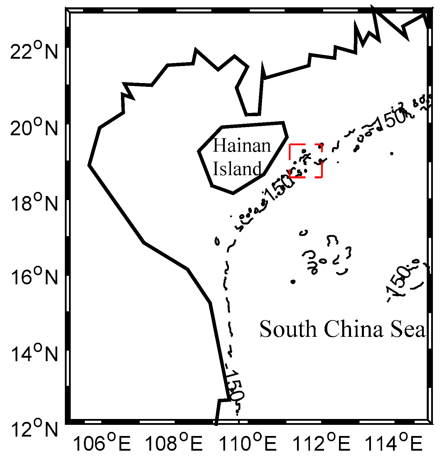
The northwest South China Sea is a potential region for FOWT-SFFC to be commissioned. The location is E 111.5 ° , N 19 ° with a water depth of 150 m, southeast of Hainan Island, as depicted in Figure 7.
The significant wave heights, mean wave periods, and 10-min mean wind speeds at 10 m used in this study are downloaded from the public dataset ERA-Interim [48] which is a re-analysis project of European Centre for Medium-Range Weather Forecasts. The temporal range of ERA is from 00:00 1 January 1979 to 18:00 31 December 2017 with time resolution of 6 h and the number of data points is 56,980. It should be noted that the downloaded data only contains mean wave periods T1 rather than zero-up-crossing periods Tz or peak wave periods Tp. In this paper Tp is derived according to the relationship with T1 [46].
To investigate the performance of FOWT-SFFC under wave and wind, three load cases (LC) are analyzed (Table 7). LC1 is a steady wind field with calm water, used to investigate the resisting overturning ability of the system. Considering that the wind thrust reaches the maximum value at the rated wind speed, the rated wind velocity V = 11.4 m/s at hub height is utilized in this load case. LC2 and LC3 are extreme load cases. It is conservatively assumed that in LC2 the extreme 10-min mean wind speed with 1-year recurrence period occurs during the sea state of 1-year extreme significant wave height. In LC3, the combination of 50-year extreme 10-min wind speed and the 50-year extreme significant wave height is employed [49]. All extrema are derived from the Gumbel model [46] with standard deviation σ = 1.283 A and mean μ = U + 0.55 A where U and 
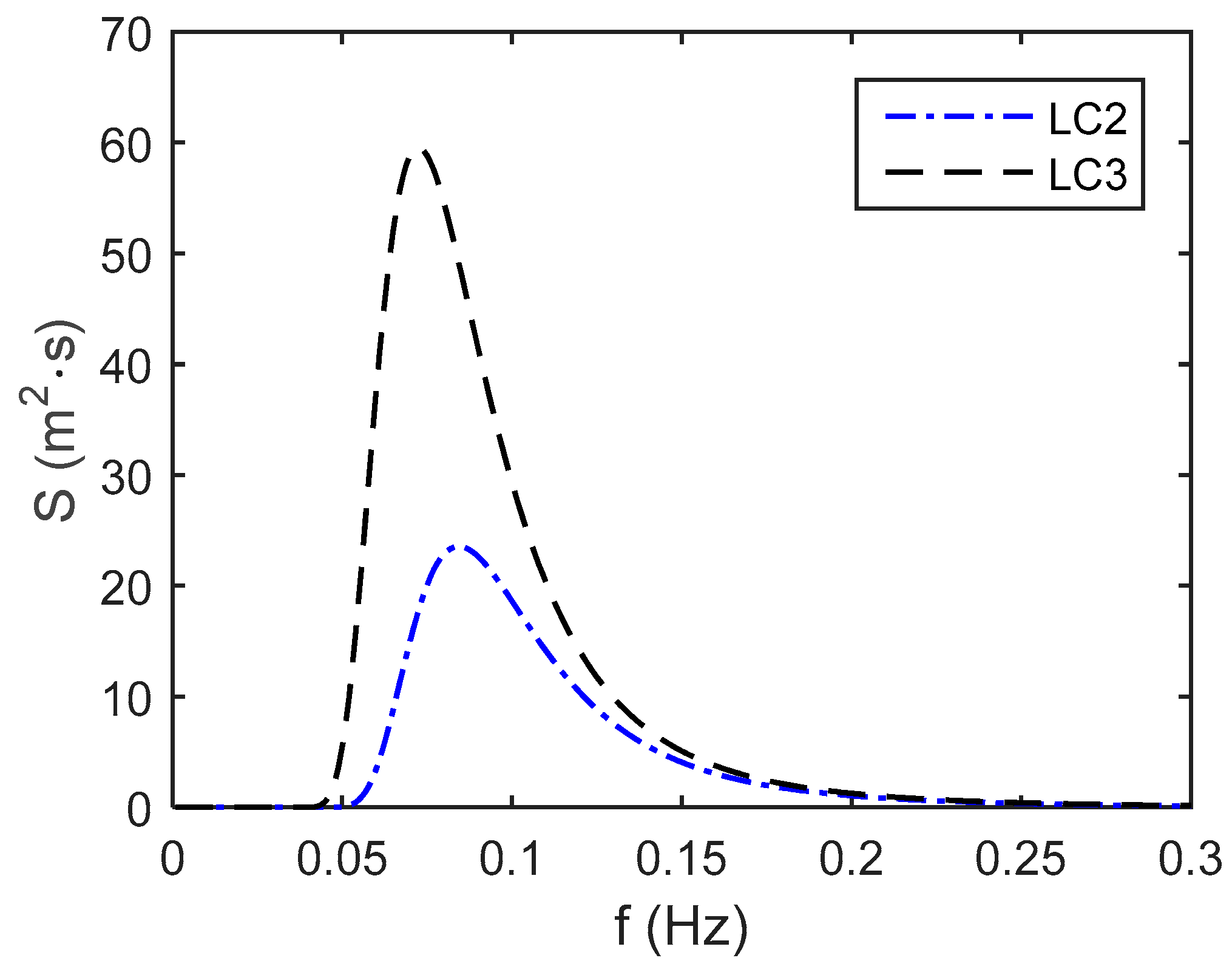
A are fitted Gumbel parameters of the downloaded site data. The irregular ocean waves are assumed to follow a Pierson-Moskowitz spectrum [46]. The mean wave periods corresponding to the 1-year and 50-year extreme sea states are determined by the conditional distribution model [50]. The Pierson-Moskowitz spectra used in LC2 and LC3 are shown in Figure 8. The linear random wave elevation and kinematics are generated by FAST.

5.3. Steady Wind Load Case

When the wind speed is 11.4 m/s, the turbine is in the state of normal operation. In FAST, all the six DOF motions of the platform are on, as well as the blades and the tower vibrations, and the power generator. Meanwhile, variable-speed control mode and pitch control mode are automatically monitored in the turbine system. Considering that the wind turbine is in the steady wind field, only 600 s are simulated. Under wind speed of 11.4 m/s, the calculated foundation motions and cross sectional stress at tower base in the equilibrium position of FOWT-SFFC, OC3Hywind and OC4DeepCwind are given in Table 8.
From Table 8, it can be concluded that the platform pitch and tower base stress of FOWT-SFFC are both the smallest among the three concepts under rated steady wind speed. It means that the anti-overturning ability of FOWT-SFFC is the strongest. Since the operating water depths of the three concepts are different (320 m, 200 m and 150 m respectively for OC3Hywind, OC4DeepCwind and FOWT-SFFC), the offset in surge cannot be used to judge performance in surge. The ratio of the foundation surge relative to water depth is used to compare the level of surge in three concepts. The respective ratios of OC3Hywind, OC4DeepCwind and FOWT-SFFC are 7.71%, 4.36% and 4.08%, indicating that the surge motion of FOWT-SFFC under the largest thrust is the smallest, a merit beneficial to the design of power cables.

5.4. Extreme Load Cases

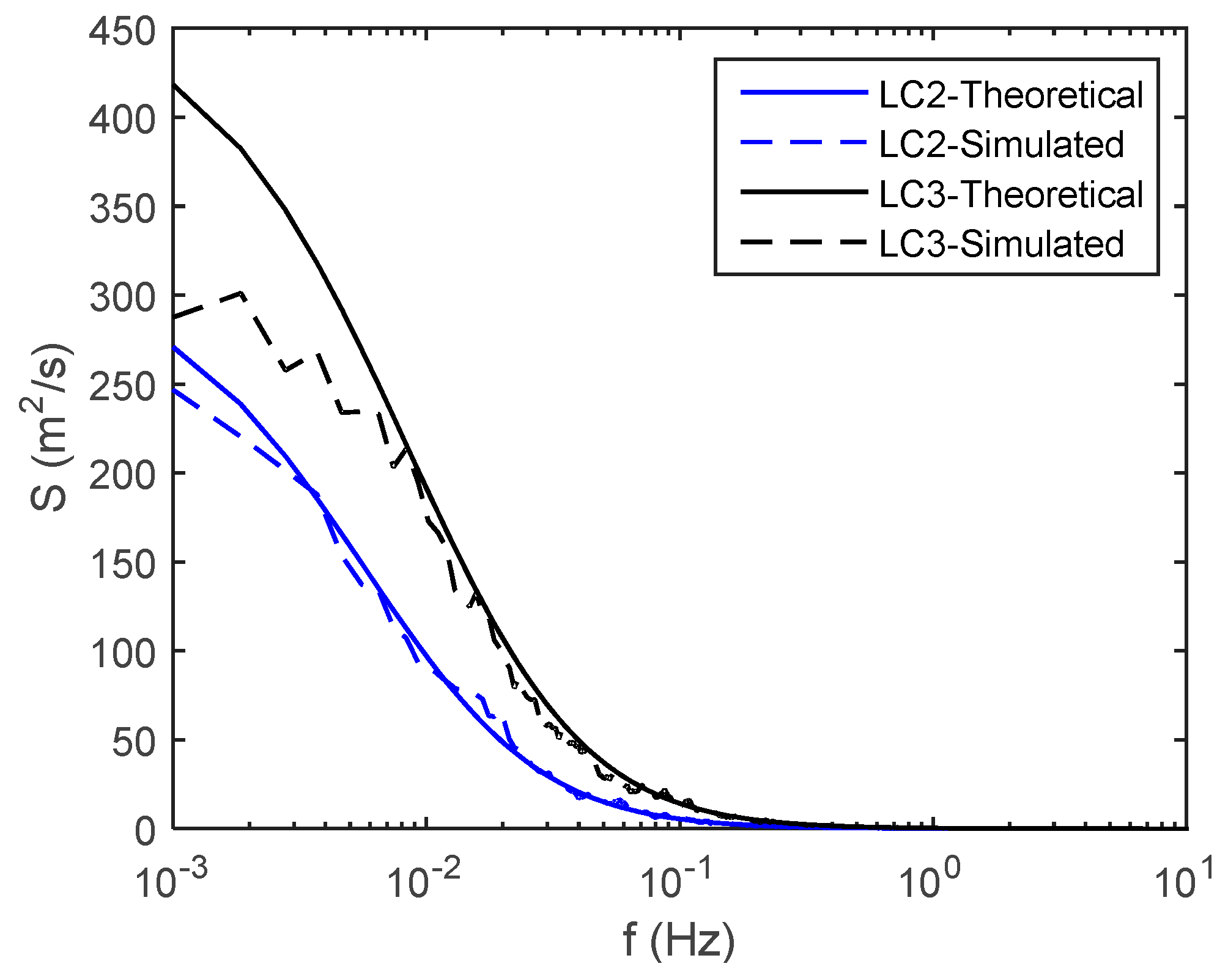
In extreme load cases LC2 and LC3, the wind conditions are modeled by a turbulence model, and wind profiles are assumed to have a power law profile. Kaimal wind spectrum model [51] is used to represent the turbulence model. Both extreme wind conditions in LC2 and LC3 have a turbulence intensity of 11% and a power law exponent of 0.11 [51]. The theoretical and FAST simulated Kaimal spectra at hub height of FOWT-SFFC in LC2 and LC3 are given in Figure 9. Besides, the wind and wave directions are assumed in line with the positive direction of axis X. In load case LC3, the mean wind speed at hub height is 28.556 m/s for FOWT-SFFC and 28.397 m/s for OC3Hywind and OC4DeepCwind, beyond the cut-out wind speed of NREL-5 MW wind turbine. As a result, the turbine has entered the parked state. Rather than initializing the blade-pitch angles to equal feathered pitch (90 degrees), the initial blade-pitch angles are set to be zeros in this parked state for the most unfavorable condition. The stochastic response in LC2 and LC3 are simulated in FAST with a time length of 11,200 s and time step of 0.0125 s. The first 400 s time history of turbine run-up is truncated. The statistical and spectral analyses are based on 3-h time duration between 400 s and 11,200 s. The response in this duration can be regarded as stationary.
Statistical quantities of foundation surge, heave and pitch motions as well as the stresses at tower base of three concepts of offshore wind turbines under LC2 and LC3 are displayed in Table 9 and Table 10.
Noticeably, in both LC2 and LC3, the surge, heave and pitch motions of FOWT-SFFC are significantly lower than those of OC3Hywind and OC4DeepCwind. In particular, the maximum surge of FOWT-SFFC is only about 26% of the OC3Hywind wind turbine in LC3. Even using the ratio of surge to water depth, the relative surge of FOWT-SFFC is still the smallest. For maximum heave of FOWT-SFFC, the motions are only 0.196 m in LC2 and 0.559 m in LC3, respectively 17% and 21% of the maximum heave of OC4DeepCwind. With regards to maximum pitch, the respective ratios of FOWT-SFFC to OC3Hywind in LC2 and LC3 are 54% and 55%. Pitch of FOWT-SFFC would not exceed 5 degrees in harsh environments. The maximum tower base stresses of FOWT-SFFC in LC2 and LC3 are almost identical to stresses in OC4DeepCwind, but over 25% lower than stresses in OC3Hywind. The statistics in Table 9 and Table 10 demonstrate that the FOWT-SFFC has least dynamic effects caused by combined random wind and waves and its seakeeping and station keeping performances are the best among three floating concepts.
It can be seen in Table 9 and Table 10 that the three floating wind turbines contain both left-skewed and right-skewed responses in LC2 and LC3, though the skew is not remarkable. The level of non-Gaussianity in FOWT-SFFC’s responses is very weak because almost all skewness values of surge, heave, pitch and tower base stress are smaller than 0.1, and kurtosis values are around 3.
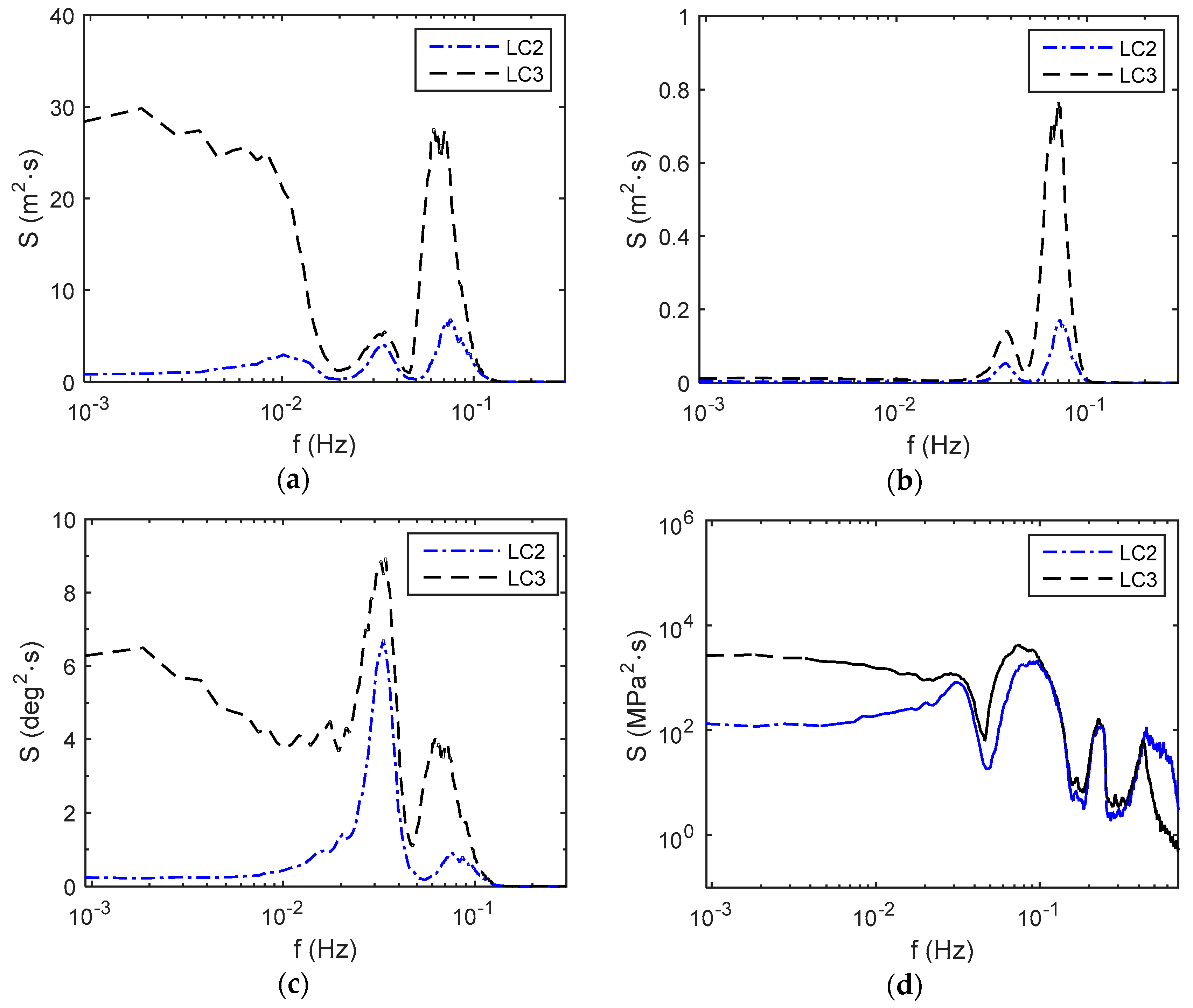
In Figure 10, the response power spectra of surge, heave, pitch and tower base stress of FOWT-SFFC for extreme load cases LC2 and LC3 are illustrated.
From Figure 10a, it can be seen that the spectrum of surge motion in LC2 has three peaks at 0.0102 Hz, 0.0333 Hz and 0.0759 Hz, which actually are around the surge natural frequency f surge (Table 5), pitch natural frequency f pitch (Table 6) and peak wave frequency f p = 1 / T p (Table 7). Obviously, pitch motion also contributes to the overall surge. The peak at f surge is the lowest, because at 0.0102 Hz the energy in wave spectrum is very small. Compared to LC2, the surge motion spectrum in LC3 also exhibit spectral peaks at f pitch and the corresponding f p , but contains much more energy at low frequencies. This is because in LC3 the wind speed is much larger and the turbine has shut down, while the assumed blade-pitch angles are all zeros, leading to maximum windward area of blades. Therefore, the wind thrust in LC3 is much larger than that in LC2. Considering also that the surge motion is heavily subjected to thrust, the appreciable energy of surge at low frequencies can thereby be manifested.
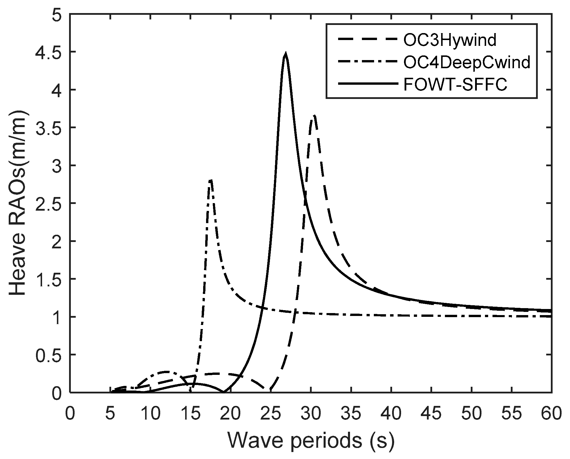
For the heave motion in Figure 10b, the responses in LC2 and LC3 are peaked around both heave natural frequency ( f heave = 0.0372   Hz in Table 6) and corresponding f p . No response amplification occurs at low frequencies, in that the wind load can hardly affect the heave motion. At f p , the response energy in LC3 is remarkably higher than that in LC2, not only because the significant wave height Hs (Table 7) is 47.3% larger, but also because of the big difference in heave RAO (Figure 5). The reason why spectral peak at f heave is much lower than that at f p is due to the too small energy density at f heave . Meanwhile, it should be recognized that as the variances of heave (equal to area under power spectral curve minus square of mean) are small, the heave motions of FOWT-SFFC are actually less than 0.2 m in LC2 and 0.6 m in LC3 (Table 9 and Table 10), evidencing the excellent motion of heave for FOWC-SFFC.
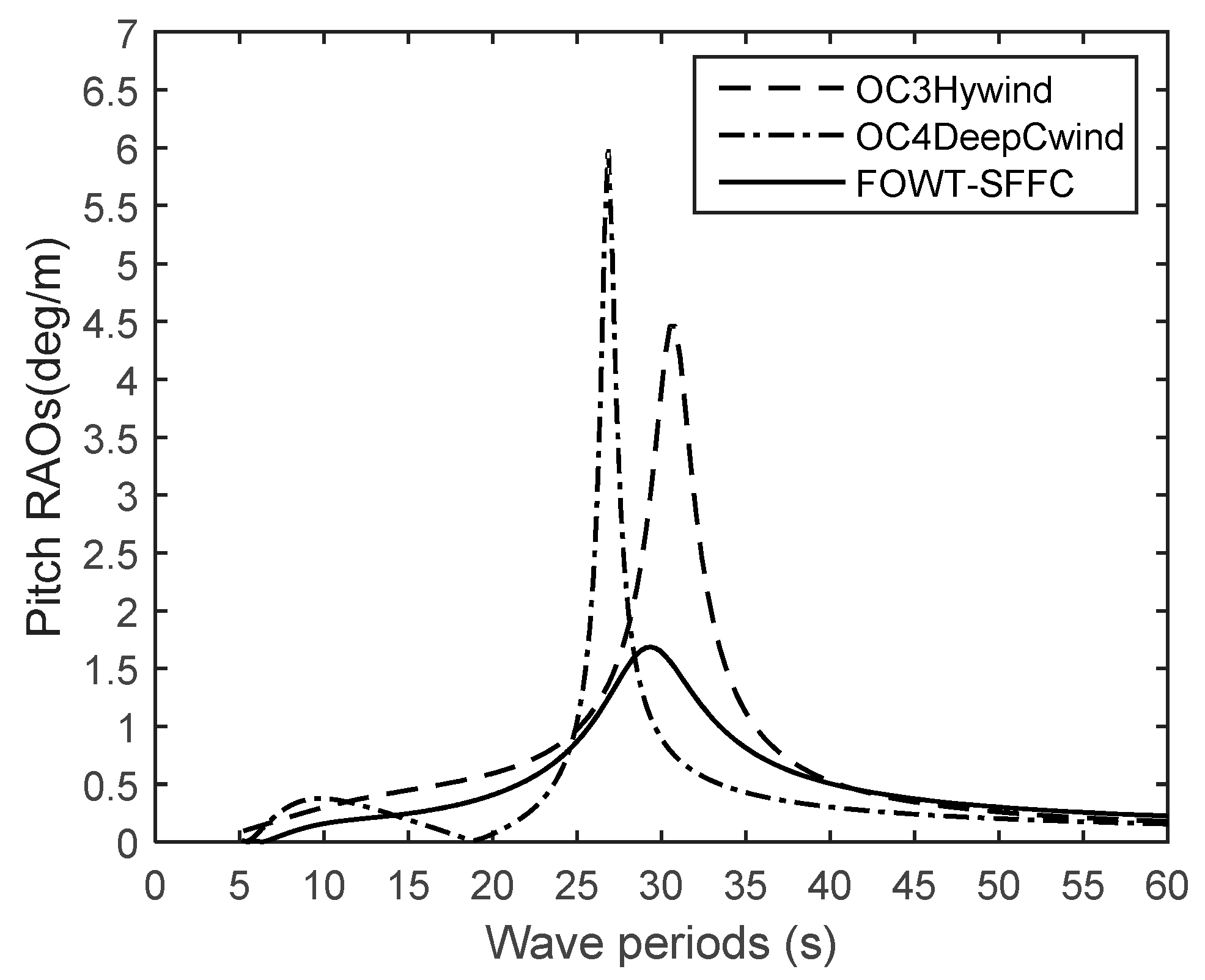
As for pitch motion in Figure 10c, there are two peaks in the response spectrum of LC2, respectively around f pitch = 0.0342   Hz and f p . But obviously more energy is concentrated around f pitch . This is due to the small damping of pitch (2.37% in Table 5) and much larger pitch RAO at T pitch than at T p (Figure 6). In LC3, as the moment induced by wind thrust has a significant effect on the pitch motion, the pitch response is pronounced at low frequencies.
When it comes to tower base stress in Figure 10d, it is more complex. In LC2 and LC3, four peaks appear in the tower base stress spectrum. The first two peaks are at frequencies around f pitch and f p . The fourth peak arises at 0.4454 Hz which is very close to the first tower fore-aft natural frequency ( f 1 = 0.4343   Hz ). Response amplifications at these three frequencies are not difficult to interpret by the knowledge of structural dynamics and the input-output spectral relation in Equation (3). However, appearance of the third peak at 0.2370 Hz in LC2 and 0.2269 Hz in LC3 is more intricate. These two frequencies are about three times f p (Table 7). Such multiple-frequency responses, or so-called superharmonic responses [52], are essentially caused by the Morison drag wave load acting on structural members of small diameter and drag load induced cage motions. Fortunately, the spectral densities at f 1 and 3 f p are much lower than densities at f pitch and f p , implying insignificant structural resonance (since f 1 is far away from f p ) and low level of non-Gaussian stress caused by Morison drag force. In addition, it can be clearly observed that in LC3 owing to wind thrust induced bending moment, the spectrum of stress at tower base has appreciable densities at low frequencies. The stress response of FOWT-SFFC is mainly contributed by wind, waves at f p and pitch motion.

6. Conclusions and Discussion

In this study, a new concept of floating offshore wind turbine that is integrated with a steel fish-farming cage (FOWT-SFFC) is exposed. Firstly, the configuration and dimensions of this concept are presented. The FOWT-SFFC possesses the essential feature of a spar buoy type offshore wind turbine with excellent hydrostatic stability, as the center of gravity of the whole system is below the center of buoyancy in its equilibrium position. Then, the hydrodynamic properties of FOWT-SFFC are investigated by the hydrodynamic program WAMIT and compared with the existing and well known OC3Hywind and OC4DeepCwind concepts. The motion RAOs reveal the superiority of seakeeping performance of FOWT-SFFC. Lastly, a coupled aero-hydro-servo-elastic model is developed in FAST, in which both potential-flow theory and Morison’s equation are taken into account to calculate the fluid forces. The comprehensive performance of FOWT-SFFC under three load cases is examined.
Through comparative study, it has been shown that the anti-overturning ability, surge, heave and pitch motions of FOWT-SFFC outperform those of OC3Hywind and OC4DeepCwind. For instance, in load case #2 the maximum heave of FOWT-SFFC is only 37% and 17% of its counterparts, and in load case #3 the maximum pitch of FOWT-SFFC is less than 4.5 degrees, while OC3Hywind and OC4DeepCwind have pitch angles exceeding 8 degrees and 6 degrees respectively. Load case #3 corresponds to a 50-year harsh sea state, in which the parked wind turbine is assumed to experience most unfavorable wind load. The spectra of responses like surge, pitch and tower base stress, contain appreciable densities at low frequencies since these responses are heavily subjected to the effects of wind. In terms of the statistics of short-term stochastic response with Gaussian waves and wind as input, it is also shown that the level of non-Gaussianity in FOWT-SFFC’s responses is weak, though superharmonic response does exist in structural response.
In addition to abovementioned hydrostatic, hydrodynamic and structural dynamic advantages in engineering technology, the FOWT-SFFC system also carries economic merits. Protected by the cage foundation, the fish farming can be executed safely in open sea with harsh environments. Also, healthier fish in water can be expected as the FOWT-SFFC system can be deployed in distant ocean. Therefore, considerable profits from fish farming help to rapidly shorten the payback period of heavy investment in wind turbine. The technological and economic benefits of FOWT-SFFC manifest a great potential in offshore industry for both power exploitation and aquaculture in deep waters.
In this paper although the NREL 5-MW wind turbine has been used as a prototype in feasibility analyses of the FOWT-SFFC concept, an upscale wind turbine larger than 10 MW can be employed, with adjustments on the fishing cage foundation. In case that the fish farming has difficulties, an upscale wind turbine to some extent will also shorten the payback period of investment. In addition, it must be noted that the performance comparisons of FOWT-SFFC with OC3Hywind and OC4DeepCwind may be not ideally fair due to their different operating depths, but the outstanding performance of FOWT-SFFC can be validated still.
Future works can be extended to investigate the nonlinear viscous damping of copper alloy nets which has been simplified as a linear damping matrix, and to identify the drag coefficients of wave forces on copper alloy nets and rectangular pontoons using model tests in ocean basin and computational fluid dynamics (CFD) simulations. In addition, as motions of FOWT-SFFC are of low frequencies; in-depth study of the effect of second-order random waves and frequency-difference wave loads is required. Furthermore, FOWT-SFFC with an upscale wind turbine (possibly larger than 10 MW) and larger steel fish-farming cage (with contained water volume greater than 250,000 m3) should be studied to probe the scalability of this integrated concept. It is important that optimization work should be carried out to meet site specific conditions.

Author Contributions

This paper shows a result of collaborative teamwork. X.Y.Z. originally proposed the concept of FOWT-SFFC and specified the structure and organization of this manuscript. Y.L. helped to refine the concept and developed the computational models in WAMIT and FAST for verification. Both authors have analyzed and carefully checked the numerical results and reviewed the article.

Acknowledgments

This research work is supported by China National Science Foundation (Grant Nos. 51379035), and the Offshore Engineering Development Projects (Grant Nos. [2015]-75 and 20141120164551165) of Shenzhen Government.

Conflicts of Interest

The authors declare no conflicts of interest.

References

  1. Henderson, A.R.; Witcher, D. Floating offshore wind energy—A review of the current status and an assessment of the prospects. Wind Eng. 2010, 34, 1–16. [Google Scholar] [CrossRef]
  2. Campanile, A.; Piscopo, V.; Scamardella, A. Mooring design and selection for floating offshore wind turbines on intermediate and deep water depths. Ocean Eng. 2018, 148, 349–360. [Google Scholar] [CrossRef]
  3. Bulder, B.H.; Henderson, A.; Huijsmans, R.H.M.; Pierik, J.T.G.; Snijders, E.J.B.; Wijnants, G.H.; Wolf, M.J. Floating Offshore Wind Turbines for Shallow Waters. In Proceedings of the European Wind Energy Conference (EWEC), Madrid, Spain, 16–19 June 2003. [Google Scholar]
  4. Heronemus, W.E. Pollution-Free Energy from Offshore Winds. In Proceedings of the 8th Annual Conference and Exposition Marine Technology Society, Washington, DC, USA, 11–13 September 1972. [Google Scholar]
  5. Butterfield, S.; Musial, W.; Jonkman, J.; Sclavounos, P. Engineering Challenges for Floating Offshore Wind Turbines. In Proceedings of the 2005 Copenhagen Offshore Wind Conference, Copenhagen, Denmark, 26–28 October 2005. [Google Scholar]
  6. Andersen, M.T. Floating Foundations for Offshore Wind Turbines. Ph.D. Thesis, Aalborg University, Aalborg, Denmark, 2016. [Google Scholar]
  7. Neville, A. Hywind Floating Wind Turbine, North Sea, Norway. Power 2009, 153, 40. [Google Scholar]
  8. Hao, K.J.; Robertson, A.N.; Jonkman, J.; Driscoll, F.; Ng, E.Y.K. Building and Calibration of a Fast Model of the Sway Prototype Floating Wind Turbine. In Proceedings of the 2013 International Conference on Renewable Energy Research and Applications (ICRERA), Madrid, Spain, 20–23 October 2013. [Google Scholar]
  9. Sethuraman, L.; Venugopal, V. Hydrodynamic response of a stepped-spar floating wind turbine: Numerical modelling and tank testing. Renew. Energy 2013, 52, 160–174. [Google Scholar] [CrossRef]
  10. Bulder, B.H.; Van, H.; Henderson, A.; Huijsmans, R.H.M.; Pierik, J.T.G.; Snijders, E.J.B.; Wijnants, G.H.; Wolf, M.J. Studie Naar Haalbaarheid van en Randvoorwaarden Voor Drijvende Offshore Windturbines; Drijfwind Project Report; TNO: Delft, The Netherlands, 2002. [Google Scholar]
  11. Roddier, D.; Cermelli, C.; Aubault, A.; Weinstein, A. Windfloat: A floating foundation for offshore wind turbines. J. Renew. Sustain. Energy 2010, 2, 53. [Google Scholar] [CrossRef]
  12. Karimirad, M.; Michailides, C. V-shaped semisubmersible offshore wind turbine: An alternative concept for offshore wind technology. Renew. Energy 2015, 83, 126–143. [Google Scholar] [CrossRef]
  13. Beyer, F.; Choisnet, T.; Kretschmer, M.; Cheng, P.W. Coupled MBS-CFD Simulation of the Ideol Floating Offshore Wind Turbine Foundation Compared to Wave Tank Model Test Data. In Proceedings of the 25th (2015) International Ocean and Polar Engineering Conference, Kona, Big Island, HI, USA, 21–26 June 2015. [Google Scholar]
  14. Robertson, A.; Jonkman, J.; Masciola, M.; Song, H.; Goupee, A.; Coulling, A.; Luan, C. Definition of the Semisubmersible Floating System for Phase II of OC4; NREL/TP-5000-60601; National Renewable Energy Laboratory (NREL): Golden, CO, USA, 2014.
  15. Adam, F.; Myland, T.; Schuldt, B.; Großmann, J.; Dahlhaus, F. Evaluation of internal force superposition on a TLP for wind turbines. Renew. Energy 2014, 71, 271–275. [Google Scholar] [CrossRef]
  16. Vita, L.; Ramachandran, G.K.V.; Krieger, A.; Kvittem, M.I.; Merino, D.; Cross-Whiter, J.; Ackers, B.B. Comparison of Numerical Models and Verification Against Experimental Data, Using PelaStar TLP Concept. In Proceedings of the ASME 2015 34th International Conference on Ocean, Offshore and Arctic Engineering, St John’s, NL, Canada, 31 May–5 June 2015; p. V009T009A047. [Google Scholar]
  17. Jonkman, J.; Musial, W. Offshore Code Comparison Collaboration (OC3) for IEA Wind Task 23 Offshore Wind Technology and Deployment; NREL/TP-5000-48191; National Renewable Energy Laboratory (NREL): Golden, CO, USA, 2010.
  18. Larsen, T.J.; Hanson, T.D. A method to avoid negative damped low frequent tower vibrations for a floating, pitch controlled wind turbine. J. Phys. Conf. Ser. 2007, 75, 012073. [Google Scholar] [CrossRef] [Green Version]
  19. Karimirad, M.; Gao, Z.; Moan, T. Dynamic Motion Analysis of Catenary Moored Spar Wind Turbine in Extreme Environmental Condition. In Proceedings of the European Offshore Wind 2009 Conference, Stockholm, Sweden, 14–16 September 2009. [Google Scholar]
  20. Driscoll, F.; Jonkman, J.; Robertson, A.; Sirnivas, S.; Skaare, B.; Nielsen, F.G. Validation of a fast model of the statoil-hywind demo floating wind turbine. Energy Procedia 2016, 94, 3–19. [Google Scholar] [CrossRef]
  21. Myhr, A.; Maus, K.J.; Nygaard, T.A. Experimental and computational comparisons of the OC3-hywind and tension-leg-buoy (TLB) floating wind turbine conceptual designs. In Proceedings of the 21st International Offshore and Polar Engineering Conference, Maui, HI, USA, 19–24 June 2011. [Google Scholar]
  22. Nielsen, F.G.; Hanson, T.D.; Skaare, B. Integrated dynamic analysis of floating offshore wind turbines. In Proceedings of the ASME 2006 25th International Conference on Ocean, Offshore and Arctic Engineering, Hamburg, Germany, 4–9 June 2006; pp. 671–679. [Google Scholar]
  23. Shin, H. Model Test of the OC3-Hywind Floating Offshore Wind Turbine. In Proceedings of the 21st International Offshore and Polar Engineering Conference, Maui, HI, USA, 19–24 June 2011. [Google Scholar]
  24. Skaare, B.; Nielsen, F.G.; Hanson, T.D.; Yttervik, R.; Havmøller, O.; Rekdal, A. Analysis of measurements and simulations from the Hywind demo floating wind turbine. Wind Energy 2015, 18, 1105–1122. [Google Scholar] [CrossRef]
  25. Statoil. World’s first floating wind farm has started production. Available online: https://www.statoil.com/en/news/worlds-first-floating-wind-farm-started-production.html (accessed on 14 June 2018).
  26. Utsunomiya, T.; Sato, T.; Matsukuma, H.; Yago, K. Experimental validation for motion of a spar-type floating offshore wind turbine using 1/22.5 scale model. In Proceedings of the ASME 2009 28th International Conference on Ocean, Offshore and Arctic Engineering, Osaka, Japan, 21–26 July 2009; pp. 951–959. [Google Scholar]
  27. Utsunomiya, T.; Nishida, E.; Sato, I. Wave response experiment on spar-type floating bodies for offshore wind turbine. In Proceedings of the 19th International Offshore and Polar Engineering Conference, Osaka, Japan, 21–26 July 2009. [Google Scholar]
  28. Utsunomiya, T.; Matsukuma, H.; Minoura, S.; Ko, K.; Hamamura, H.; Kobayashi, O.; Sato, I.; Nomoto, Y.; Yasui, K. At sea experiment of a hybrid spar for floating offshore wind turbine using 1/10-scale model. In Proceedings of the ASME 2010 29th International Conference on Ocean, Offshore and Arctic Engineering, Shanghai, China, 6–11 June 2010; pp. 529–536. [Google Scholar]
  29. International Renewable Energy Agency (IRENA). Floating foundations: A game changer for offshore wind. Available online: http://www.irena.org/-/media/Files/IRENA/Agency/Publication/2016/IRENA_Offshore_Wind_Floating_Foundations_2016.pdf (accessed on 14 June 2018).
  30. Komatsu, M.; Kumamoto, H.; Ohta, M.; Tanaka, H.; Mori, H.; Miyazaki, S. Development of offshore wind turbine floater that blends into Japanese waters. Mitsubishi Heavy Ind. Tech. Rev. 2016, 53, 30–39. [Google Scholar]
  31. GICON. Chronicle: April 2018-GICON® SOF-New tank tests for Autumn 2018 confirmed. Available online: http://www.gicon-sof.de/en/sof-chronik.html (accessed on 14 June 2018).
  32. Jonkman, J. Definition of the Floating System for Phase IV of OC3; NREL/TP-500-47535; National Renewable Energy Laboratory (NREL): Golden, CO, USA, 2010.
  33. Jonkman, J.; Butterfield, S.; Musial, W.; Scott, G. Definition of a 5-MW Reference Wind Turbine for Offshore System Development; NREL/TP-500-38060; National Renewable Energy Laboratory (NREL): Golden, CO, USA, 2009.
  34. Griffith, D.T.; Ashwill, T.; Resor, B. Large Offshore Rotor Development: Design and Analysis of the Sandia 100-m Wind Turbine Blade. In Proceedings of the 53rd AIAA/ASME/ASCE/AHS/ASC Structures, Structural Dynamics and Materials Conference, 20th AIAA/ASME/AHS Adaptive Structures Conference AIAA, Honolulu, HI, USA, 23–26 April 2012. [Google Scholar]
  35. Liu, J.; Thomas, E.; Manuel, L.; Griffith, D.; Ruehl, K.; Barone, M. Integrated system design for a large wind turbine supported on a moored semi-submersible platform. J. Mar. Sci. Eng. 2018, 6, 9. [Google Scholar] [CrossRef]
  36. Thomas, E.; Liu, J.; Goyal, A.; Manuel, L. Long-Term Loads on a Large Offshore Wind Turbine Supported by a Semi-Submersible Platform. In Proceedings of the 34th Wind Energy Symposium, San Diego, CA, USA, 4–8 January 2015. [Google Scholar]
  37. Bayati, I.; Belloli, M.; Bernini, L.; Fiore, E.; Giberti, H.; Zasso, A. On the functional design of the DTU 10 MW wind turbine scale model of lifes50+ project. J. Phys. Conf. Ser. 2016, 753. [Google Scholar] [CrossRef]
  38. Vryhof Anchors, B.V. Anchor Manual 2010–The Guide to Anchoring; Vryhof Anchors B.V.: Capelle a/d Yssel, The Netherlands, 2010; pp. 147–148. [Google Scholar]
  39. DNV GL. Offshore Standard: Position Mooring; DNVGL-OS-E301; DNV GL AS: Høvik, Oslo, Norway, 2015. [Google Scholar]
  40. Esteban, M.D.; Couñago, B.; López-Gutiérrez, J.S.; Negro, V.; Vellisco, F. Gravity based support structures for offshore wind turbine generators: Review of the installation process. Ocean Eng. 2015, 110, 281–291. [Google Scholar] [CrossRef]
  41. Chinadaily: China Delivers Batch of Ocean Farming Facilities to Norway. Available online: http://www.chinadaily.com.cn/a/201706/15/WS59bbeb00a310ded8ac18cb7a.html (accessed on 16 July 2018).
  42. WAMIT, Inc. WAMIT User Manual, Version 7.0; WAMIT, Inc.: Chestnut Hill, MA, USA, 2013. [Google Scholar]
  43. AeroHydro, Inc. MultiSurf User Manual, Version 8.0; AeroHydro, Inc.: Southwest Harbor, ME, USA, 2011. [Google Scholar]
  44. Jonkman, J.M.; Buhl, M.L. Fast User’s Guide—Updated August 2005; NREL/EL-500-38230; National Renewable Energy Laboratory (NREL): Golden, CO, USA, 2005.
  45. Barltrop, N.D.P.; Adams, A.J. Dynamics of Fixed Marine Structures, 3rd ed.; Butterworth-Heinemann Ltd.: Oxford, UK, 1991; pp. 310–319. ISBN 978-0-7506-1046-9. [Google Scholar]
  46. DNV. Recommended Practice: Environmental Conditions and Environmental Loads; DNV-RP-C205; Det Norske Veritas: Høvik, Oslo, Norway, 2007. [Google Scholar]
  47. NWTC Information Portal (FAST). Available online: https://nwtc.nrel.gov/FAST8 (accessed on 14 June 2018).
  48. European Centre for Medium-Range Weather Forecasts Public Dataset ERA Interim. Available online: http://apps.ecmwf.int/datasets/data/interim-full-daily/levtype=sfc/ (accessed on 14 June 2018).
  49. IEC. IEC 61400-3, Wind Turbines-Part 3: Design Requirements for Offshore Wind Turbines, 3rd ed.; International Electrotechnical Commission: Geneva, Switzerland, 2008. [Google Scholar]
  50. Moan, T.; Gao, Z.; Ayala-Uraga, E. Uncertainty of wave-induced response of marine structures due to long-term variation of extratropical wave conditions. Mar. Struct. 2005, 18, 359–382. [Google Scholar] [CrossRef]
  51. IEC. IEC 61400-1, Wind Turbines-Part 1: Design Requirements, 3rd ed.; International Electrotechnical Commission: Geneva, Switzerland, 2005. [Google Scholar]
  52. Zheng, X.Y.; Liaw, C.Y. Response spectrum estimation for fixed offshore structures with inundation effect included: A price’s theorem approach. J. Offshore Mech. Arct. Eng. 2004, 126, 971–974. [Google Scholar] [CrossRef]
Figure 1. Illustration of the concept of floating offshore wind turbine with a steel fish-farming cage (FOWT-SFFC).
Applsci 08 01229 g001
Figure 2. Side view of the fishing cage.
Applsci 08 01229 g002
Figure 3. Mooring line layout (top view).
Applsci 08 01229 g003
Figure 4. Modeling of wetted surfaces of FOWT-SFFC in MultiSurf.
Applsci 08 01229 g004
Figure 5. Heave response amplitude operators (RAOs) of three concepts of offshore wind turbines.
Applsci 08 01229 g005
Figure 6. Pitch response amplitude operators (RAOs) of three concepts of offshore wind turbines.
Applsci 08 01229 g006
Figure 7. A presumed offshore area in South China Sea for FOWT-SFFC.
Applsci 08 01229 g007
Figure 8. Pierson-Moskowitz wave spectra for LC2 and LC3.
Applsci 08 01229 g008
Figure 9. Kaimal wind spectra at hub height of FOWT-SFFC for LC2 and LC3.
Applsci 08 01229 g009
Figure 10. Response power spectra of foundation motions and tower base stresses of FOWT-SFFC under LC2 and LC3. (a) Surge motion spectrum; (b) heave motion spectrum; (c) pitch motion spectrum; (d) tower base stress spectrum.
Applsci 08 01229 g010
Table 1. Dimensions of fishing cage structural members.
Structural MembersSectional Diameter or Breadth × Height (m)Length (m)Wall Thickness (m)
Central Column6.5800.027
Side Column3.876.210.02
Radial Pontoon *4 × 1.841.290.02
Ring Pontoon *4 × 1.827.770.02
Top Radial Brace1.525.250.012
Top Ring Brace1.519.470.012
Upper Side Brace1.238.210.01
Lower Side Brace1.241.600.01
* The shape of pontoon is rectangular.
Table 2. Mass breakdown of fishing cage.
Key ComponentsMass (kg)CG * (m)
Steel Structure3,417,340−37.10
Ballast Concrete9,142,116−64.49
Living Quarter200,00015
Copper alloy Nets133,000−36.73
Total12,892,456−55.71
* Center of gravity (CG) is measured from SWL (Figure 2).
Table 3. Mooring line parameters in water depth of 150 m.
Class of mooring linesStudless chain R4, Diameter: 78 mm
Number of mooring lines8
Angle between adjacent lines45°
Depth of fairleads below SWL40 m
Distance between fairleads and axis Z40.6 m
Distance between anchors and axis Z648 m
Unstretched mooring line length632.5 m
Mooring line mass density122 kg/m
Equivalent mooring line diameter0.1407 m
Equivalent mooring line extensional stiffness8.167 × 108 N
Transverse drag coefficient of mooring line2.4
Table 4. Key parameters of FOWT-SFFC in static equilibrium position.
Displaced volume13,431 m3
Waterplane area147.279 m2
Operating depth150 m
ZCG−49.892 m
ZCB−41.837 m
Transverse metacentric height GMT12.414 m
Heave restoring coefficient1,480,421 N/m
Pitch and roll restoring coefficient−5,085,917,468 N∙m/rad
Table 5. Damping ratios and natural periods derived from FAST decay tests for the moored FOWT-SFFC without fishing nets.
PropertiesSurgeSwayHeaveRollPitchYaw
Damping Ratio4.89%4.84%3.79%2.45%2.34%2.97%
Natural Period (s)81.3380.7026.4027.6527.7578.23
Natural Frequency (Hz)0.01230.01240.03790.03620.03600.0128
Table 6. Damped natural period of the FOWT-SFFC without mooring forces.
PropertiesHeavePitch
Natural Period (s)26.8529.36
Natural Frequency (Hz)0.03720.0341
Table 7. Load cases.
Load CaseWind Speed (U10, m/s)Wind PropertyElevationWave Parameters
Hs (m)Tp (s) f p   ( H z )
LC111.4 Steady Hub
LC215.2Random Z = 10 m4.7111.860.0843
LC322.3RandomZ = 10 m 6.9413.810.0724
Table 8. Foundation motions and tower base stress under steady wind speed of 11.4 m/s.
Concepts of FOWTSurge (m)Heave (m)Pitch (deg)Tower Base Stress (MPa)
OC3Hywind24.69−0.5304.9475.48
OC4DeepCwind8.73−0.0463.4869.68
FOWT-SFFC6.12−0.0932.9666.95
Table 9. Statistics of foundation motions and tower base stress under LC2.
ResponsesVariablesFOWT-SFFCOC3HywindOC4DeepCwind
Surge (m)Max5.063018.85009.0880
Min1.44109.47802.7570
Mean3.389213.58475.5974
Std0.53831.15040.8175
Skewness−0.00920.09540.1320
Kurtosis2.78083.09853.2612
Heave (m)Max0.19600.52291.1630
Min−0.2430−0.8688−1.0220
Mean−0.0305−0.1674−0.0042
Std0.06340.18820.3164
Skewness0.03240.06460.0616
Kurtosis2.88242.89652.8050
Pitch (deg)Max3.04205.62504.6150
Min0.25210.6218−0.0755
Mean1.53232.69601.8177
Std0.36220.63010.6209
Skewness0.12470.08380.1612
Kurtosis3.17393.25473.0542
Stress (MPa)Max76.2169103.361976.3925
Min−9.0734−29.2106−4.4899
Mean32.227238.487033.8732
Std11.011317.320810.2659
Skewness−0.0021−0.03050.0857
Kurtosis2.92393.02343.0380
Table 10. Statistics of foundation motions and tower base stress under LC3.
ResponsesVariablesFOWT-SFFCOC3HywindOC4DeepCwind
Surge (m)Max8.753033.250014.4000
Min1.28909.21202.6090
Mean4.966220.20747.7644
Std1.13693.20951.4784
Skewness0.08960.070.0527
Kurtosis2.76892.99473.0070
Heave (m)Max0.55860.80132.6480
Min−0.6706−1.7200−2.3570
Mean−0.0623−0.37080.0008
Std0.13740.33290.7258
Skewness−0.0208−0.00880.0064
Kurtosis3.55782.86502.9258
Pitch (deg)Max4.41208.10006.0420
Min0.09990.1925−0.3114
Mean2.21623.85562.5198
Std0.61911.06190.8608
Skewness0.04460.13570.1640
Kurtosis2.85942.96103.0697
Stress (MPa)Max99.7660153.788599.4315
Min−13.8067−27.5297−0.6489
Mean45.625053.507346.6412
Std15.434323.599312.3898
Skewness0.00360.04580.0606
Kurtosis2.91512.96393.1234

