Review

Adaptive Lenses Based on Soft Electroactive Materials

1
Department of Polymer Nano-Science and Technology, Chonbuk National University, Jeonju, Jeonbuk 54896, Korea
2
College of Optics and Photonics/CREOL, University of Central Florida, Orlando, FL 32816, USA
*
Author to whom correspondence should be addressed.
Appl. Sci. 2018, 8(7), 1085; https://doi.org/10.3390/app8071085
Submission received: 13 June 2018 / Revised: 27 June 2018 / Accepted: 3 July 2018 / Published: 4 July 2018
(This article belongs to the Special Issue Adaptive Optics for Biomedical Imaging)

Abstract

:

Featured Application

adaptive lenses based on electroactive materials have potential applications in imaging, biometrics, sensing, beam steering, machine vision, and laser beam modulation with more merits.

Abstract

Soft electroactive materials including dielectric elastomer actuators (DEAs) and polyvinyl chloride (PVC) gels have recently been extensively investigated. These smart materials can effectively respond to an electric field, resulting in shape deformation. In addition to artificial muscles, actuators, sensors, and micro-electromechanical systems, they can be used to prepare various adaptive lenses with unique features such as a simple fabrication, compact structure, good flexibility, and light weight. In contrast to DEAs, PVC gels can provide exciting opportunities for emerging applications in imaging, sensing, optical communication, biomedical engineering, and displays. In this review paper, the underlying physical mechanisms of these two electroactive materials are explained first, and then some recent progress in their application in macro-sized lenses and microlens arrays is presented. Finally, future perspectives of the PVC gels are discussed.

1. Introduction

Adaptive-focus lenses have attractive applications in machine vision, mobile phone cameras, eyeglasses, image surveillance systems, target tracking, biometrics, and electronic displays. Unlike a glass lens whose focal length is fixed, the focal length of an adaptive lens can be tuned by changing the refractive index of the employed medium or the shape of the surface profile. For the former mechanism, liquid crystal (LC) is an effective medium because its optical anisotropy and dielectric anisotropy can be varied by an electric field. By controlling the LC directors of the LC lens cell with an electric field, a gradient refractive index distribution across the lens aperture can be changed. As a result, the focal length of the LC lens can be tuned. An LC lens offers a relatively fast response time, good stability, and low power consumption. However, most of the LC lenses are polarization dependent, and the fabrication process is rather complicated [1,2,3,4,5,6]. To overcome these problems, polymer-dispersed liquid crystal [7] or polymer-stabilized blue phase LC [8,9] can be considered. However, the phase change of these optically isotropic nanostructures is only one-third of a homogeneous aligned LC, thus, their dynamic range is rather limited, and the required voltage is usually very high.
In comparison with the abovementioned LC lens, which is based on refractive index change, the adaptive lens based on surface profile change presents a large dynamic range, scalable aperture, and better optical performances. Various approaches, such as an elastic membrane [10,11,12], electrowetting effect [13,14,15], dielectrophoretic effect [16,17,18], ferrofluidic piston actuation [19,20,21], and soft electroactive actuators [22,23,24,25,26,27,28,29,30], have been demonstrated. Each approach has its own strengths and weaknesses. For instance, in an elastic membrane lens based on fluidic pressure, at least one elastic membrane is employed as its boundary. The shape of the membrane can be changed by pumping liquid in and out of its chamber using a piezoelectric actuator [12] or other mechanical methods [10,11,31,32]. Depending on the volume variation of the liquid in the lens chamber, a large focus power change can be easily obtained. This type of lens usually faces the challenges of shape distortion, a gravitational effect, and mechanical actuation. Additional concerns come from the elastic membrane itself. Most elastic membranes, such as polydimethylsiloxane (PDMS), are physically stable in a dry condition. However, many liquids can cause them to shrink or swell under direct contact. These factors will degrade the optical performances of the lenses.
Adaptive lenses based on an electrowetting and dielectrophoretic (dielectric) effect share some common features. For example, they belong to a liquid-liquid system, in which one liquid forms a droplet, while the other liquid fills the surrounding of the droplet. The purposes of these lenses with such a liquid-liquid system are mainly for minimizing the gravitational effect, lubricating the substrate surface, and enhancing the mechanical stability in case of shaking, vibrating, or shocking. In an electrowetting lens, salt water is the key liquid employed. The shape of the water is deformed by the generated electrostatic force [33,34]. In a dielectric lens, both liquids are nonconductive but with different dielectric constants. The shape of the liquid-liquid interface is controlled by the generated dielectric force [16,35]. A lens with a liquid-liquid system has some inherent issues: (1) the nonconductive liquid in the lens cell can be easily charged during actuation, leading the lens to work inefficiently; (2) a bulky structure because of two liquids and two substrates; and (3) multiple reflection and scattering due to substrate/liquid and liquid-liquid surfaces, degrading the optical performances of the lenses.
A liquid lens based on ferrofluidic piston actuation can exhibit a large dynamic range and good optical performances [19,20,21]. Either a magnet or electromagnet can be used as the ferrofluidic piston. A pitfall of such a lens is that the focal length of the lens is difficult to adjust precisely. This is because the lens part and the piston part are separated; the effective area of the lens is small, and the lens cell is bulky. Using an electromagnet as the piston will noticeably consume the electric power because the generated magnetic force is through an electric current rather than voltage.
Recently, soft electroactive actuators have attracted great attention for preparing adaptive lenses. Various electroactive actuators such as a photo-polymer [24,36,37], hydrogel gel [22,23], conducting polymer artificial muscle [38], ionic polymer-petal composite artificial muscle [39], carbon nanotube artificial muscle [40], dielectric elastomer actuator (DEA) artificial muscle [26,27], and plasticized polyvinyl chloride (PVC) gel [41,42], have been developed. These actuators can respond to external stimuli such as pH, temperature, light, magnetic field, or electric field. Due to their fascinating properties, such as their compactness, ability for miniaturization, and ease of manufacturability, they have found promising applications in artificial muscles, sensors, micro-electromechanical systems, and microlenses. Among them, dielectric elastomer actuators and PVC gels are especially attractive for fabricating adaptive lenses because they are highly transparent and their shape can be deformed effectively with an outstanding durability in an electric field. Moreover, they do not need any solvent during actuation.
In this review paper, we focus on the adaptive lenses based on DEA materials and PVC gels. We first describe the underlying operation mechanisms, and then present some recent progress in the macro-sized lenses and microlens arrays (MLAs). Finally, future perspectives of PVC gel lenses are analyzed.

2. DEA Lens

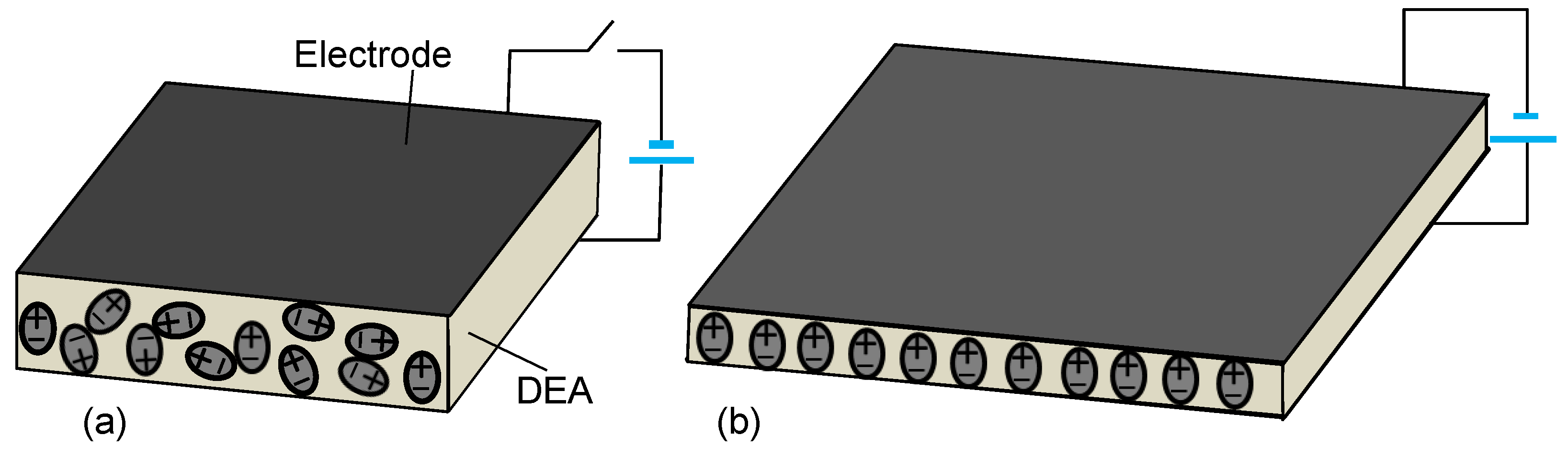
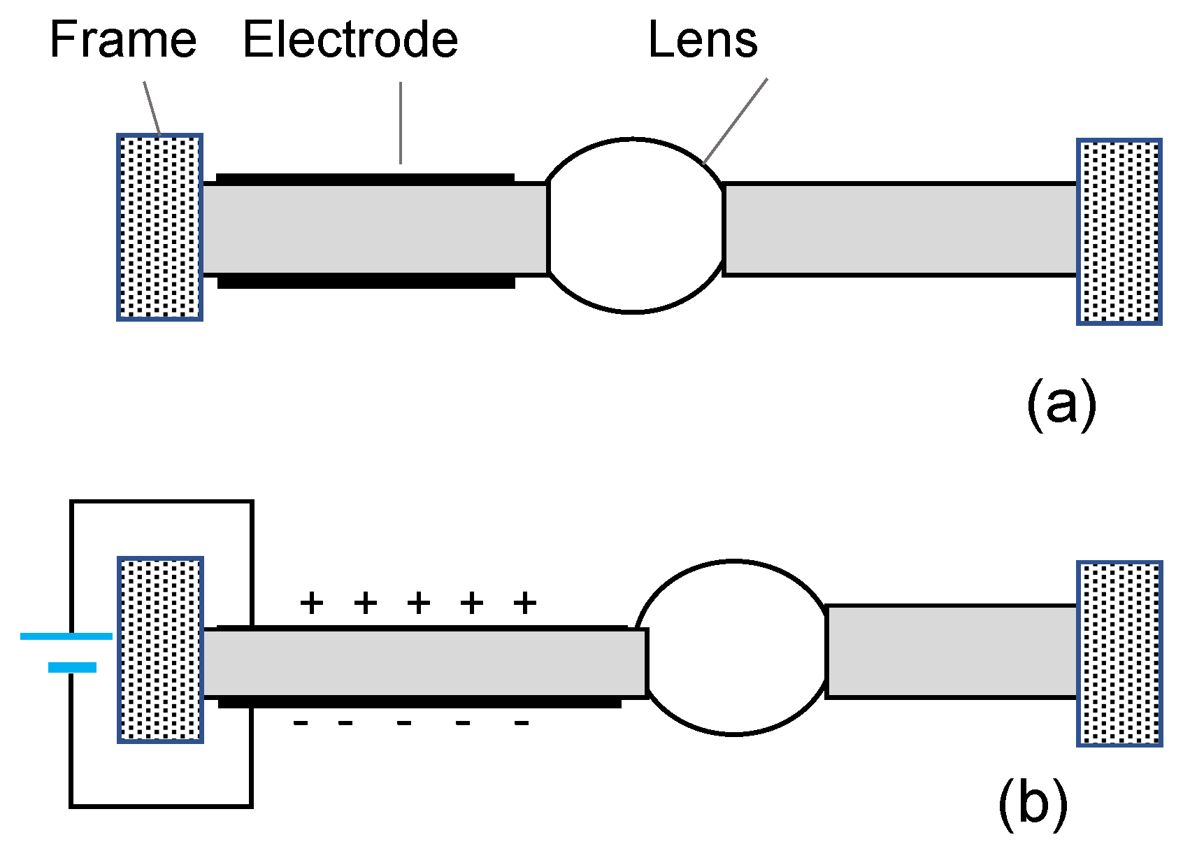
2.1. Working Principle

DEAs are the most common type of artificial muscles. They are smart materials with great developmental potential. They have the advantages of large deformation, fine elastic recovery, good flexibility, low power consumption, a fast response time, and high efficiency. Figure 1 depicts the working principle of a DEA. It consists of an elastomeric dielectric membrane (typically 10–100 µm thick), sandwiched between two compliant electrodes, thus forming a rubbery capacitor [43,44,45,46]. In the voltage-off state, the molecules in the DEA are dipolar, and they present random orientations, as shown in Figure 1a. By applying a DC voltage to the electrodes, the molecules are reoriented by the longitudinal electric field. The attraction of positive charges and negative charges exerts a pressure, called Maxwell’s stress, to the DEA. If the Maxwell stress is strong enough to overwhelm the mechanical stiffness (or modulus), it contracts in the thickness direction, and expands in the film plane directions, as shown in Figure 1b. As a result, the thickness of the DEA decreases. The relationship of actuation pressure P and the applied voltage V can be expressed by [43]:
P = ε 0 ε   ( V / t ) 2 ,
where ε0 and ε are the permittivity of free space and the dielectric constant of the elastomer, respectively, and t is the thickness of the DEA. Most DEAs reported in the literature use a proprietary acrylic elastomer film from 3 M named VHB as the dielectric elastomer membrane, strains of the DEAs are in the order of 10~35%, and maximum values reach 300% [43]. DEAs can be used as actuators capable of producing very large strains (up to 1700% surface strain) with a high electrical breakdown strength [44]. In comparison, silicone elastomers can also be used as the dielectric membrane for DEAs, leading to devices with a response speed 1000 times faster than acrylic elastomers, due to their reduced mechanical losses [45]. Films of carbon powder or grease loaded with carbon black were early choices as electrodes for the DEAs. Here, we use a DEA to fabricate various adaptive lenses.

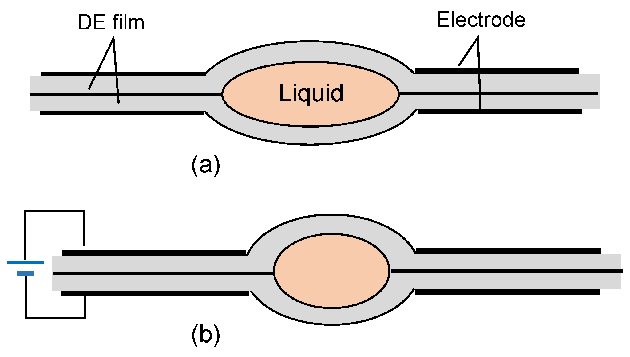
2.2. Liquid Encapsulation

Inspired by the lens structure of a human eye, a lens is fabricated by encapsulating a small amount of liquid between two DEA films [26]. The side-view structure of the lens is shown in Figure 2. The liquid constrained by the DEA films presents a biconvex shape. The electrode in this area is removed. Since the liquid and boundary DEA films are symmetrical and transparent, the liquid exhibits a lensing behavior. In the relaxed state, the stretched boundaries cause the radius of the curvature of the liquid to be maximal, as shown in Figure 2a. Therefore, the focal length of the liquid lens is the longest. When a DC voltage is applied, the peripheral DEA films expand synchronously due to the actuated pressure. At the same time, the boundary of the liquid is relaxing, and the liquid is contracting, as Figure 2b shows. As a result, the radius of the curvature of the liquid is reduced, as is the focal length of the lens.
In the experiment, a lens with such a structure was fabricated and its imaging properties were characterized. As the diameter decreases from ~7.65 mm to ~7.13 mm, the radius of curvature decreases from Ro = 19.55 mm (with discharged electrodes) to R = 14.38 mm (for an applied electric field E = 58 V/µm), resulting in a focal length change from f0 = 22.73 mm to f = 16.72 mm. The peak current is ~40 µA during charging at 4 kV, which corresponds to a peak power of ~160 mW. The response time is in the second level or below. Adaptive lenses based on this device structure usually have the advantages of a large dynamic range, good optical performance, and good stability. Although the driving voltage is high, the power consumption is at the microwatt level or below. Since the actuator part is outside the optical path, a significant fraction of the lens’ lateral area is occupied by the actuating mechanism. Therefore, the usable optical area is reduced.
To solve this issue, we may replace the black electrode (carbon conductive grease) of the DEA film with a transparent electrode (single walled carbon nanotube mats) for the lens [27]. Because the actuator part covered by the electrode can be the boundaries of the liquid lens, the effective optical area in contrast to the total area of the device is largely increased. In a lens demo, the optical transmittance at λ = 550 nm is over 88%, and the focal length is changed from ~36 mm to ~72 mm when the voltage increases from 0 to 5000 V. The response time is below 1 s. Because it is not necessary to extremely deform the shape of the lens, the operating voltage is safe without the concern of electrical field breakdown.
An adaptive lens based on this configuration faces some challenges: (1) It is not easy to tightly encapsulate a liquid; (2) for a large-aperture lens, the gravitational effect which distorts the lens shape is not negligible; (3) it is difficult to fabricate a microlens; and (4) the driving voltage is extremely high because the electrodes are separated by two DEA films.

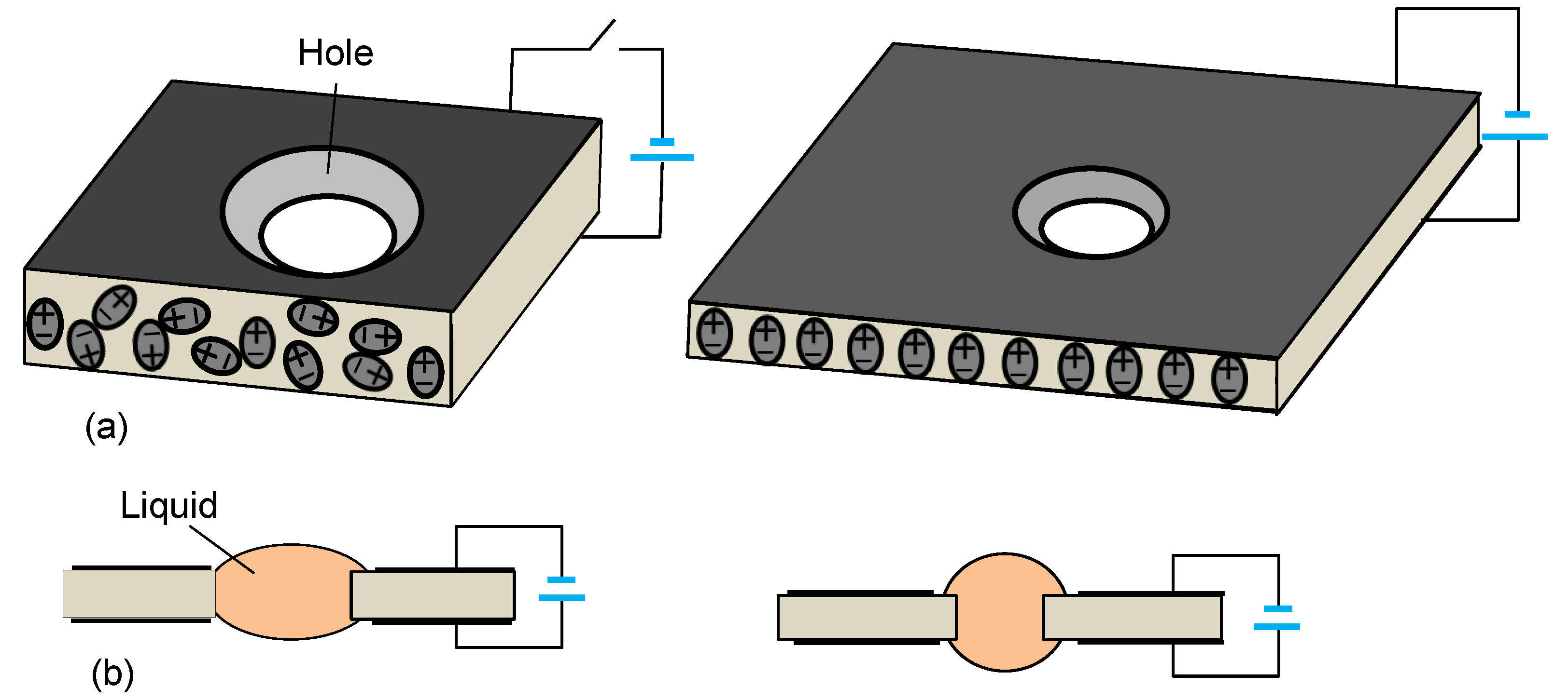
2.3. Free Constrained Boundary

To simplify the fabrication procedure, one DEA film can be used to actuate a liquid lens [47]. The lens structure is shown in Figure 3. The center area of the DEA film is drilled with a through hole. Figure 3a shows the film in a relaxed state (left) and stressed state (right). In the relaxed state, the diameter of the hole is at its maximum. In a stressed state, the DEA film expands, and the diameter of the hole decreases. Then, a small liquid droplet is used to fill the hole, as shown in Figure 3b. In the relaxed state (left), the droplet partially wets its border with a biconvex shape. The radius of curvature of the droplet is at its maximum (left). On the other hand, in a stressed state, the diminished hole squeezes the droplet, leading its surface profile to change (right). Similar to the lens shown in Figure 2, the focal length of the droplet can be tuned.
To make a demo, we drilled a hole on a ~0.2-mm thick DEA film. The diameter of the hole is ~1.85 mm and it was filled with glycerol (glycerol, no ~1.47). The volume of glycerol is ~0.6 mm3. To observe the image property, a tiny object (Kitty) was placed at ~6 cm under the lens. Figure 4 shows the observed image at V = 0 (left) and V = 2.6 kV (right). The right image is shrunk greatly, indicating that the focal length of the droplet is tunable.
As the voltage increases from 0 to 2.6 kV, the focal length decreases from ~5.5 mm to ~3 mm. The measured resolution is ~143 lp/mm at V = 2.6 kV, and the total (rise + decay) response time is ~0.8 s. The major advantages of such a lens are the: simple fabrication process, miniature size, and high optical performance. However, the lens should be placed in a horizontal position in order to avoid a gravitational effect because of free-constrained boundaries. To increase the stability of the lens in case of shocking, shaking, and vibrating, the diameter of the hole should be kept at a micro-sized scale.
Using the DEA film with a through hole, a solid lens can be shifted in a transverse direction [48]. Figure 5 shows the structure and operation method of such a solid lens. A DEA film is stretched by a rigid frame. A solid lens is trapped in the hole (Figure 5a). Only the surfaces of the left DEA film have electrodes. The solid lens can be prepared by curing an optical adhesive droplet in the hole. By applying a voltage across the electrodes (Figure 5b), the left DEA film is stretched, while the right DEA film shrinks. As a result, the lens shifts toward the right. The lens can conduct a reciprocating motion if the voltage is removed. When this lens system integrates with other lenses, a variable focal length can be obtained. This lens system has potential applications in imaging and beam steering, as well as optical switching, without the concern of a gravitational effect.

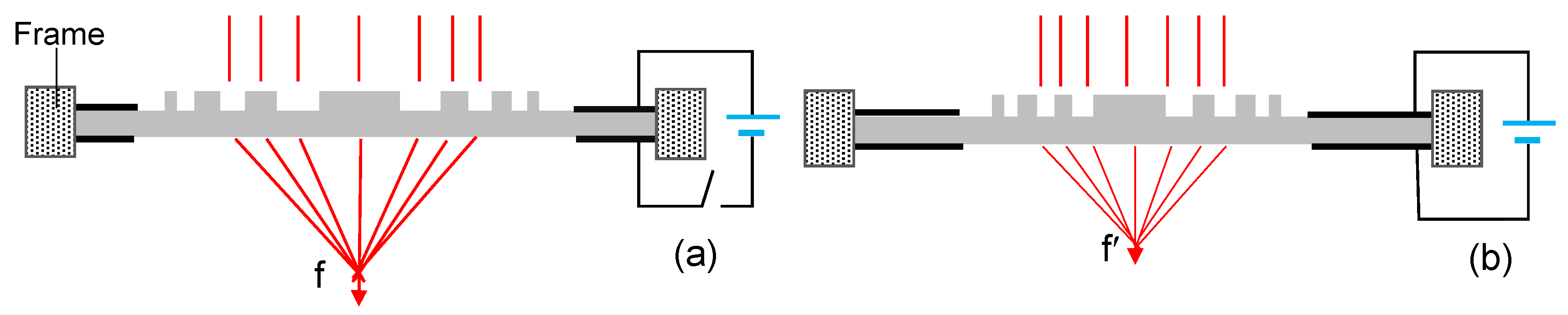
2.4. Fresnel Zone Plate Lens

In addition to the above lenses driven using DEAs, a DEA film can be used to prepare a binary phase Fresnel zone plate (FZP) lens [49]. The DEA film is patterned with a series of concentric zones, and the electrode is compatible with the DEA film. The DEA film is stretched on an external rigid frame. The side-view structure of the device is shown in Figure 6. In the voltage-off state, the radius of the nth zone (rn) is at its maximum (Figure 6a). The focal length (f) of the lens is defined by f = r n 2 /(nλ), where the integer n indicates the nth Fresnel zone, rn is the radius of the zone, and λ is the wavelength of the incident light. Therefore, in the voltage-off state, the focal length is the longest. When a sufficiently high voltage is applied across the electrodes, the FZP undergoes contraction, leading the radius of the zones to reduce (Figure 6b). Therefore, the focal length (f’) of the FZP lens is reduced. Because it does not employ any liquid, the device is compact and mechanically stable. This device has potential use in optical communication and sensing. Similar to a conventional FZP, the diffraction efficiency of the FZP lens is low (the theoretical limit is 40.5%). Moreover, the fabrication procedure is quite complicated.

3. PVC Gel Lens

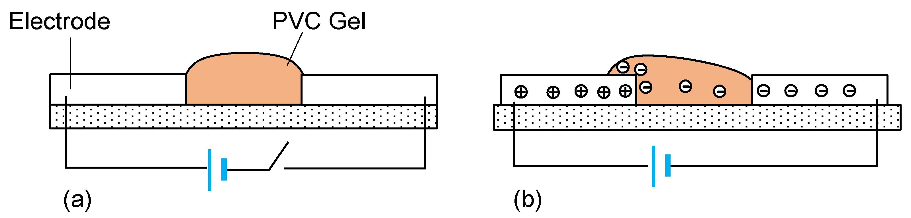
3.1. Working Principle

Most polymeric actuators can only be driven in water, and the deformation can only be obtained by bending. As a comparison, PVC gels including the plasticizer do not need any solvent to work, so they can be operated in air. PVC gels are unique actuator materials and can be used to develop various actuators with large deformation and different motions by designing appropriate boundary conditions. It has been reported that maximum strain could reach 1000% and still recover to its original shape in an electric field. It is suggested that the deformation accompanies a huge electrorheological process [50,51]. PVC gels are the most promising smart materials for an artificial muscle in terms of the applied DC voltage and the response rate. The electric efficiency of PVC gels is better than that of conventional polymeric actuators.
PVC gels that deform in response to an electric field have been investigated by Hirai et al. [41,42]. A PVC gel is a mixture of PVC power and a plasticizer. It is a jelly-like, soft, and dielectric material. Figure 7 shows the operation mechanism of a PVC gel device [50]. The PVC gel is sandwiched by two stripe electrodes. Suppose the PVC gel has a symmetrical shape between the electrodes in the voltage-off state, as shown in Figure 7a. By applying a sufficiently high DC voltage to the electrodes, electric charges (electrons) are injected from the cathode into the PVC gel, and the charged plasticizer molecules shift toward the electrode connected to the anode. The charged molecules accumulate in the region near the positively charged electrode. The electric charges promote the electrostatic adhesiveness of the PVC gel onto the anode, and a creeping deformation appears on the positively charged electrode surface, as shown in Figure 7b. When the DC voltage is removed, the PVC gel can return to the original shape. The PVC gel acts as a dielectric (it is definitely not a good conductor), so the current leakage is very small (typically about several micro-amperes).
In a PVC gel, the PVC and plasticizer can be mixed at any weight ratio. However, the concentration of the plasticizer in the mixture can largely affect the properties of the PVC gel [28,42]. For example, Table 1 lists some parameters of a PVC gel prepared using PVC and dibutyl adipate (DBA) with different concentrations. DBA is a typical plasticizer. When the concentration of DBA is increased, the PVC gel tends to be softer. This leads the Yong’s modulus to decrease and the transmittance to increase, and results in a larger strain with a lower driving voltage.

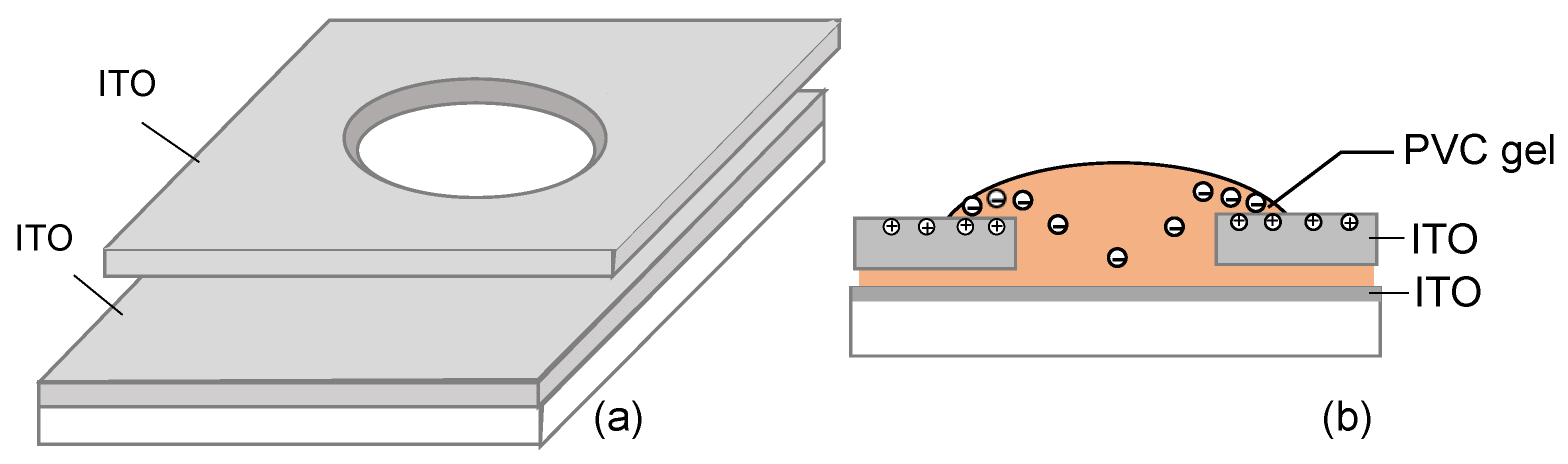
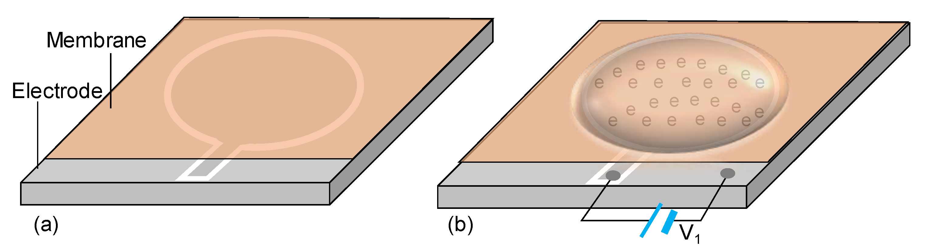
3.2. Macro-Sized Circular Lens

The earliest PVC gel lens was demonstrated using a top indium tin oxide (ITO) electrode, PVC gel, and bottom ITO electrode [25]. The structure of the lens is shown in Figure 8. The two ITO electrodes are placed together with a thin gap, as shown in Figure 8a. Only the top electrode has a through hole. A PVC gel (not shown) fully fills the hole. In the voltage-off state, the PVC gel has a convex shape in the hole. By applying a DC voltage to the electrode, for example, the top (bottom) ITO electrode connects to the anode (cathode), electrons are injected to the PVC gel from the bottom electrode. The plasticizer molecules carried the electrons to migrate toward the top electrode. Due to electrostatic repulsion, the PVC gel displays creep deformation on the top electrode, causing the surface profile of the PVC gel to change, as shown in Figure 8b.
In this lens, the PVC gel was prepared from PVC powder, tetrahydrofuran (THF), and dibutyl phthalate (DBP). DBP is a typical plasticizer. PVC powder was dissolved in a THF/DBP mixture first, and then the mixture was used to fill the hole of the electrode. After evaporating the solvent THF, a PVC gel was formed. Although a PVC gel with different weight ratios can be prepared, the gel with ~10 wt % PVC and ~90 wt % DBP can present the highest bending displacement by voltage due to the low elastic modulus. In the PVC gel, the PVC forms rigid cross-linked chains (or polymer network) and the DBP molecules are dispersed as multi-domains in the chains. For the demonstrated lens, the diameter of the hole is 2 mm and the thickness of the top electrode is ~100 μm. By applying a voltage changed from 0 to 400 V, the focal length of the PVC lens can be tuned from ~10.65 mm to ~10.77 mm. When the voltage is continuously increased, the dynamic range of the focal length can be widened. In contrast to the operating voltage for a DEA lens, the required voltage for the PVC lens is relatively low.
Based on the structure shown in Figure 8, Kim et al. [28] prepared a PVC lens. The PVC gel is prepared using PVC powder and nontoxic DBA as the plasticizer. The weight ratio of PVC/DBA is 1:9. The diameter of the hole is ~1.5 mm, and the gap of the two substrates is ~1 mm. By increasing the voltage from 300 V to 800 V, the focal length can be tuned from ~3.8 mm to ~14.3 mm. At V = 800 V, the measured current is just ~15 μA. The computed maximum power consumption is ~12 mW. In another lens demonstrated by the same group [52], the PVC/acetyl tributyl citrate was prepared at a 1:10 weight ratio. The transmittance of the PVC gel was measured to be ~86.6% at λ = 550 nm. As the operating voltage increases from 0 to 500 V, the focal length changes from ~5 mm to ~15 mm. The response time of the PVC gel lens is ~1 s.
The above PVC lenses also exhibit similar features, such as simple fabrication, a compact structure, and a good mechanical stability. However, the dynamic range is rather limited, even if the operating voltage is high (>500 V). For the first lens, its creeping rate is slow due to some memory effect [25,51].

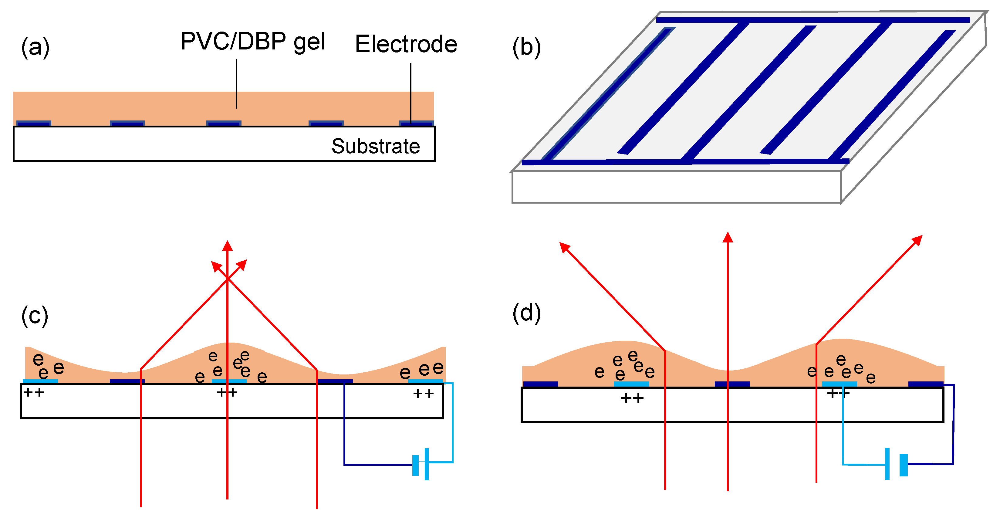
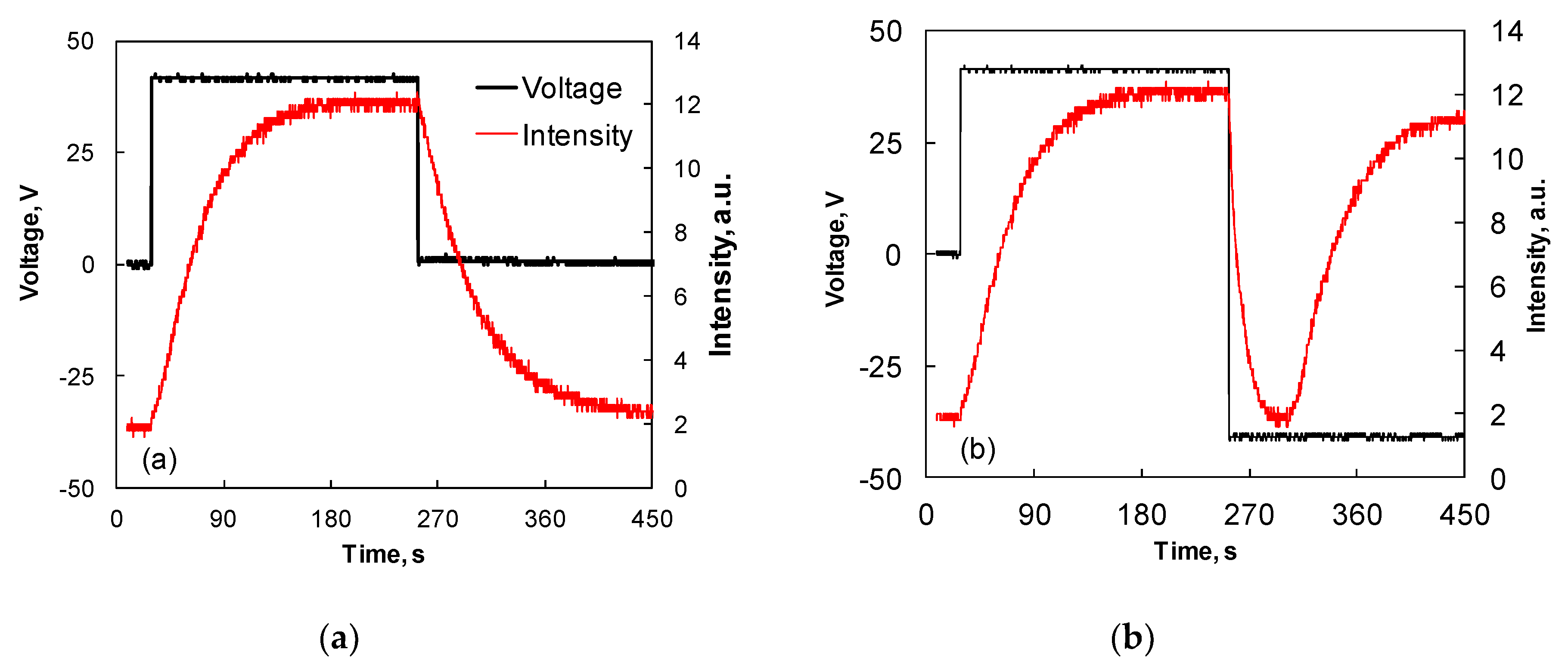
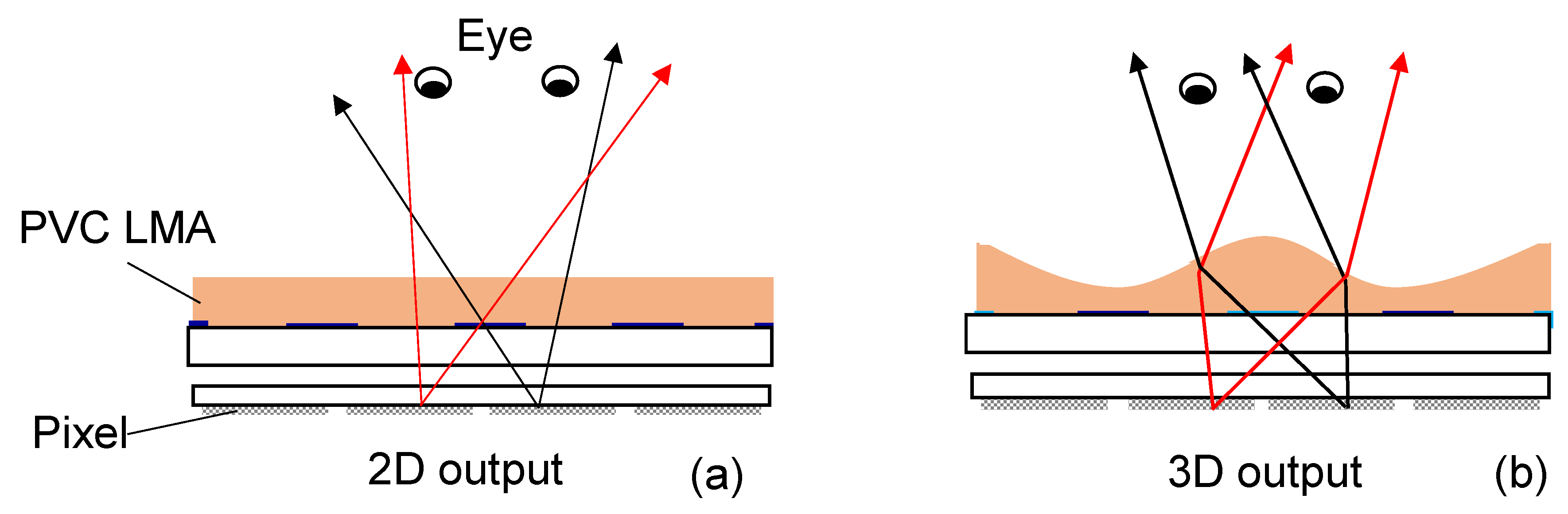
3.3. Lenticular Microlens Array

According to the operation mechanism, a PVC gel is particularly attractive for making microlens. One method is to use an interdigitated electrode to actuate the PVC gel [29,30]. Figure 9 illustrates the device structure of the lens and the driving method. The cross-sectional structure of the device is depicted in Figure 9a. It consists of a glass substrate, an electrode, and PVC/DBP gel. The PVC gel cast on the substrate forms a flat membrane.
The electrode on the glass substrate has an interdigitated pattern, as given in Figure 9b. By applying a DC voltage, the charged plasticizer molecules shift toward the anode electrode. Due to the electrostatic repulsive force, the surface of the PVC membrane is undulated with a wavy configuration (Figure 9c). Due to the surface tension, the membrane is smoothly curved. Therefore, the membrane functions as a lenticular microlens array (LMA). When the incident light passes through the LMA, it can be converged by the convex surface. If the polarity of the voltage is inverted, then the charged molecules shift to the new anode electrode, causing the trough of the waves to be the crest (Figure 9d). When the voltage is removed, the membrane can be restored to its flat shape.
For a prepared MLA, the aperture of each lenticular lens in the array is 40 μm, and the thickness of the PVC/DBP membrane is ~25 μm in the null voltage state. The refractive index of the PVC/DBP (1:9 by weight) gel was measured to be n ~1.49. By increasing the voltage from 30 V to 50 V, the focal length of the MLA changes from infinity to ~88 μm. The response time is in the range from several seconds to tens of seconds, depending on the operating DC voltage.
The response time includes the rise time (τr) and fall time (τf), which is defined as the transmittance change between 10% and 90%. The response time can be measured using a pulse voltage to impact the PVC membrane, as shown in Figure 10. By applying a +40 V pulse voltage with 172-s duration to the PVC membrane (Figure 10a), the light transmittance goes through three stages: rise, saturation, and fall. In the rising stage, the surface of the PVC membrane is undulated with a wavy shape. In the saturation stage, the wavy shape is stable. In the restoring stage, the undulated PVC membrane slowly returns to being flat. The rise time depends on the applied voltage, but the decay time is a natural process, so the total response time (τr + τf) is 102 s + 118 s. To improve τf, we could apply a polarity-inverted voltage to the undulated PVC membrane, as shown in Figure 10b. When V = −40 V is continuously applied to the electrode, τf is reduced to ~30 s. In this period, the PVC membrane returns to its flat shape. Afterwards, the PVC membrane is undulated again by the +40 V pulse. This process has been explained in Figure 9.
According to the results shown in Figure 10, the polarity-inverted voltage can largely decrease τf, so that τf << τr. This is because τr and τf correspond to the shape constructing and shape collapsing, respectively. During the shape constructing, the generated electrostatic force needs to overcome the surface tension of the PVC membrane. Therefore, the effective force used to deform the PVC membrane is reduced. During the shape collapsing, the polarity-inverted voltage can redistribute the charged molecules, leading the electrostatic repulsion to reduce quickly. With the aid of the surface tension, τf can be significantly shortened.
In addition to the lenticular lens, circular MLA can also be fabricated [53] The structure of a single microlens in the array is shown in Figure 11. The electrode in the center region is patterned with a circular zone. The center electrode and the outer electrode are separated by a small gap. A thin PVC/DBP membrane is coated on the electrode, as shown in Figure 11a. By applying a voltage (V1) across the electrodes (center electrode to anode), the gel migrates towards the center area and is deformed with a convex shape (Figure 11b). The electrode with a zone-array pattern can be prepared. Therefore, a circular MLA using PVC/DBP gel can be fabricated.
According to the structure shown in Figure 11, we fabricated a circular MLA. The radius of each circular electrode is 50 μm and the gap of the ring is 20 μm. The distance between adjacent rings is 30 μm. The PVC membrane coated on the electrode is prepared by mixing PVC and DBP at the ratio of ~1:9 by weight. The thickness of the membrane is ~35 μm. Figure 12 shows the light intensity distribution of an He-Ne laser beam (λ = 633 nm) passing through the MLA. At V = 0, the laser beam presents a Gaussian shape, and light intensity at the center area is relatively strong, as shown in Figure 12a. At V ~65 V, each microlens in the array can strongly focus the laser beam. As a result, a peak intensity array is formed, as shown in Figure 12b. When the voltage is removed, the PVC gel begins to discharge. The membrane recovers the initial shape, and the focusing behavior disappears. For this MLA, its focal length can be tuned from ~300 μm to ~160 μm as the voltage increases from 20 V to 65 V. By applying ±65 V pulsed voltage to the electrode, it takes ~5 s for the membrane to recover to its initial flat shape.
Compared to the macro-sized PVC lenses, the required voltage for actuating the MLA is significantly reduced. As mentioned above, such a lens only consists of a glass substrate and a PVC membrane, thus the device is compact and lightweight. We also tested the device stability. After over 5000 cycles of sequential actuation, the switching time of the PVC membrane could still repeat well. It has been reported that such PVC gels exhibit excellent durability after continuous driving for over two years [51].
Since the focal length of the lenticular PVC MLA is tunable, it can be used for switchable two-dimension (2D)/three-dimensional (3D) displays. According to Figure 9, the PVC MLA can be integrated with a 2D display device. The device structure of the display system is sketched in Figure 13. In the voltage-off state, the MLA has no focusing effect, as shown in Figure 13a, so the eyes see a 2D display. In the voltage-on state, each lenticular microlens in the array covers two pixels. For each lenticular microlens, the image coming from the right pixel can only be seen by the left eye, while the image from the left pixel can only be detected by the right eye, as shown in Figure 13b. By combining the two images, the eyes can see a 3D image out of the 2D panel. In contrast to a lenticular LC MLA which needs a polarizer and two glass substrates for switchable 2D/3D displays [54,55], the PVC MLA is extremely compact because it does not need additional parts to hold, so the device system is lightweight. Because PVC gels can firmly adhere to a glass substrate, the prepared PVC LMA has a good mechanical stability. By optimizing the film morphology and the pattern of the comb-shape electrodes, the optical performances of the proposed LMAs can be further improved. For a large sized PVC MLA, the surface flatness of the PVC gel and the gravity effect will not be the main concerns when it is placed in a vertical position.
Because PVC gels manipulate light by shape deformation when driven by the DC electric field, they can be used to for various photonic devices including a lens, beam steerer, grating, and actuator. These devices have promising applications in imaging, beam steering, biometrics, optical communications, and electronic displays. Considering the operating voltage and the response time, PVC gels are very suitable for miniaturized and micro-sized devices. Currently they are still in an infancy stage. With the continuous development on soft polymeric materials and innovative device structures, these devices are expected to be technologically important in the near future.

4. Conclusions

Various approaches or materials can be used to prepare adaptive lenses. Among them, soft electroactive materials are the emerging intelligent materials which can be used as lens materials or lens actuators. Smart electroactive materials including DEA actuators and PVC gels are two strong contenders for making adaptive lenses. Unlike other soft polymer materials, these two materials can be used as lens materials and lens actuators equally well. Moreover, they have some common features when they are used as the lens materials, e.g., solvent-free condition, compact structure, flexibility, and lightweight. In a DEA lens, the DEA film must be uniformly stretched using a rigid frame. Due to the intrinsic character, a DEA-based lens needs a very high DC voltage (kilovolts) to actuate although the current is at the microampere level. As a comparison, a PVC gel can be firmly laminated to a substrate without additional support. On the other hand, PVC gels can be effectively deformed using a relatively low DC voltage. For a macro-sized lens, the operating voltage is in the order of hundreds of volts. For a microlens or microlens array operated with in-plane actuation, the required voltage is about tens of volts. Furthermore, PVC gels have the advantages of simple fabrication, a high durability, and low power consumption (about micro-ampere level). With the development of materials, innovative device structures, and optimized driving methods, PVC gels would find promising applications not only for sensitive smart devices, but also for microlens and microlens arrays.

Funding

H. Ren was financially supported by the National Research Foundation (NRF) of Korea (Grant Number 2016R1D1A1B04934256), and S.-T.W. is indebted to Intel Corp. for partial financial support.

Conflicts of Interest

The authors declare no conflicts of interest.

Abbreviations

The following abbreviations are used in this manuscript:
DEAsDielectric Elastomer Actuators
PVCPolyvinyl Chloride
LCLiquid Crystal
PDMSPolydimethylsiloxane
MLAsMicrolens Arrays
DCDirect Current
FZPFresnel zone plate
ITOIndium Tin Ixide
DBPDibutyl Phthalate
DBADibutyl-Adipate
2DTwo-Dimension
3DThree-Dimension

References

  1. Sato, S. Liquid-crystal lens-cells with variable focal length. Jpn. J. Appl. Phys. 1979, 18, 1679–1684. [Google Scholar] [CrossRef]
  2. Ye, M.; Sato, S. Optical properties of liquid crystal lens of any size. Jpn. J. Appl. Phys. 2002, 41, L571–L573. [Google Scholar] [CrossRef]
  3. Ren, H.; Fan, Y.H.; Gauza, S.; Wu, S.T. Tunable flat liquid crystal spherical lens. Appl. Phys. Lett. 2004, 84, 4789–4791. [Google Scholar] [CrossRef]
  4. Lu, L.; Sergan, V.; Heugten, T.V.; Duston, D.; Bhowmik, A.; Bos, P.J. Surface localized polymer aligned liquid crystal lens. Opt. Express 2013, 21, 7133–7138. [Google Scholar] [CrossRef] [PubMed]
  5. Sun, J.; Xu, S.; Ren, H.; Wu, S.-T. Reconfigurable fabrication of scattering-free polymer network liquid crystal prism/grating/lens. Appl. Phys. Lett. 2013, 102, 161106. [Google Scholar] [CrossRef]
  6. Hassanfiroozi, A.; Huang, Y.-P.; Javidi, B.; Shien, H.-P.D. Dual layer electrode liquid crystal lens for 2D/3D tunable endoscopy imaging system. Opt. Express 2016, 24, 8527–8538. [Google Scholar] [CrossRef] [PubMed]
  7. Ren, H.; Fan, Y.-H.; Lin, Y.-H.; Wu, S.-T. Tunable-focus microlens arrays using nanosized polymer-dispersed liquid crystal droplets. Opt. Commun. 2005, 247, 101–106. [Google Scholar] [CrossRef]
  8. Lin, Y.-H.; Chen, H.-S.; Lin, H.-C.; Tsou, Y.-S.; Hsu, H.-K.; Li, W.-Y. Polarizer-free and fast response microlens arrays using polymer-stabilized blue phase liquid crystals. Appl. Phys. Lett. 2010, 96, 113505. [Google Scholar] [CrossRef]
  9. Li, Y.; Wu, S.T. Polarization independent adaptive microlens with a blue-phase liquid crystal. Opt. Express 2011, 19, 8045–8050. [Google Scholar] [CrossRef] [PubMed]
  10. Zhang, D.Y.; Lien, V.; Berdichevsky, Y.; Choi, J.; Lo, Y.H. Fluidic adaptive lens with high focal length tunability. Appl. Phys. Lett. 2003, 82, 3171–3172. [Google Scholar] [CrossRef]
  11. Ren, H.; Fox, D.; Anderson, A.; Wu, B.; Wu, S.-T. Tunable-focus liquid lens controlled using a servo motor. Opt. Express 2006, 14, 8031–8036. [Google Scholar] [CrossRef] [PubMed]
  12. Schneider, F.; Draheim, J.; Kamberger, R.; Waibel, P.; Wallrabe, U. Optical characterization of adaptive fluidic silicone-membrane lenses. Opt. Express 2009, 14, 11813–11821. [Google Scholar] [CrossRef]
  13. Kuiper, S.; Hendriks, B.H.W. Variable-focus liquid lens for miniature cameras. Appl. Phys. Lett. 2004, 85, 1128–1130. [Google Scholar] [CrossRef]
  14. Smith, N.R.; Hou, L.; Zhang, J.; Heikenfeld, J. Fabrication and demonstration of electrowetting liquid lens arrays. J. Disp. Technol. 2009, 5, 411–413. [Google Scholar] [CrossRef]
  15. Grilli, S.; Miccio, L.; Vespini, V.; Finizio, A.; De Nicola, S.; Ferraro, P. Liquid micro-lens array activated by selective electrowetting on lithium niobate substrates. Opt. Express 2008, 16, 8084–8093. [Google Scholar] [CrossRef] [PubMed]
  16. Cheng, C.C.; Yeh, J.A. Dielectrically actuated liquid lens. Opt. Express 2007, 15, 7140–7145. [Google Scholar] [CrossRef] [PubMed]
  17. Ren, H.; Xianyu, H.; Xu, S.; Wu, S.-T. Adaptive dielectric liquid lens. Opt. Express 2008, 16, 14954–14960. [Google Scholar] [CrossRef] [PubMed]
  18. Xu, S.; Lin, Y.J.; Wu, S.-T. Dielectric liquid microlens with well-shaped electrode. Opt. Express 2009, 17, 10499–10505. [Google Scholar] [CrossRef] [PubMed]
  19. Xiao, W.; Hardt, S. An adaptive liquid microlens driven by a ferrofluidic transducer. J. Micromech. Microeng. 2010, 20, 055032. [Google Scholar] [CrossRef]
  20. Cheng, H.-C.; Xu, S.; Liu, Y.; Levi, S.; Wu, S.T. Adaptive mechanical-wetting lens actuated by ferrofluids. Opt. Commun. 2011, 284, 2118–2121. [Google Scholar] [CrossRef]
  21. Malouin, B.; Vogel, M., Jr.; Olles, J.; Chen, L.; Hirsa, A. Electromagnetic liquid pistons for capillarity-based pumping. Lab Chip 2011, 11, 393–397. [Google Scholar] [CrossRef] [PubMed]
  22. Dong, L.; Agarwal, A.K.; Beebe, D.J.; Jiang, H. Adaptive liquid microlenses activated by stimuli-responsive hydrogels. Nature 2006, 442, 551–554. [Google Scholar] [CrossRef] [PubMed]
  23. Ehrick, J.D.; Stokes, S.; Bachas-Daunert, S.; Moschou, E.A.; Deo, S.K.; Bachas, L.G.; Daunert, S. Chemically tunable lensing of stimuli-responsive hydrogel microdomes. Adv. Mater. 2007, 19, 4024–4027. [Google Scholar] [CrossRef]
  24. Xu, S.; Ren, H.; Lin, Y.J.; Moharam, M.G.J.; Wu, S.T.; Tabiryan, N. Adaptive liquid lens actuated by photo-polymer. Opt. Express 2009, 17, 17590–17595. [Google Scholar] [CrossRef] [PubMed]
  25. Hirai, T.; Ogiwara, T.; Fujii, K.; Ueki, T.; Kinoshita, K.; Takasaki, M. Electrically active artificial pupil showing amoeba-like pseudopodial deformation. Adv. Mater. 2009, 21, 2886–2888. [Google Scholar] [CrossRef]
  26. Carpi, F.; Frediani, G.; Turco, S.; De Rossi, D. Bioinspired tunable lens with muscle-like electroactive elastomers. Adv. Funct. Mater. 2011, 21, 4152–4158. [Google Scholar] [CrossRef]
  27. Shian, S.; Diebold, R.M.; Clarke, D.R. Tunable lenses using transparent dielectric elastomer actuators. Opt. Express 2013, 21, 8669–8676. [Google Scholar] [CrossRef] [PubMed] [Green Version]
  28. Bae, J.W.; Yeo, M.; Shin, E.-J.; Park, W.-H.; Lee, J.E.; Nam, B.-U.; Kim, S.-Y. Eco-friendly plasticized poly (vinyl chloride)–acetyl tributyl citrate gels for varifocal lens. RSC Adv. 2015, 5, 94919–94925. [Google Scholar] [CrossRef]
  29. Xu, M.; Jin, B.; He, R.; Ren, H. Adaptive lenticular microlens array based on voltage-induced waves at the surface of polyvinyl chloride/dibutyl phthalate gels. Opt. Express 2016, 24, 8142–8148. [Google Scholar] [CrossRef] [PubMed]
  30. Li, X.; Zhou, Z.; Ren, H. Dynamic response of a lenticular microlens array using a polyvinyl chloride gel. Opt. Eng. 2017, 56, 127103. [Google Scholar]
  31. Sugiura, N.; Morita, S. Variable-focus liquid-filled optics lens. Appl. Opt. 1993, 32, 4181–4186. [Google Scholar] [CrossRef] [PubMed]
  32. Ren, H.; Wu, S.T. Variable-focus liquid lens with changing aperture. Appl. Phys. Lett. 2005, 86, 211107. [Google Scholar] [CrossRef]
  33. Vallet, M.; Berge, B.; Vovelle, L. Electrowetting of water and aqueous solutions on poly (ethylene terephthalate) insulating films. Polymer 1996, 37, 2465–2470. [Google Scholar] [CrossRef]
  34. Berge, B.; Peseux, J. Variable focal lens controlled by an external voltage: An application of electrowetting. Eur. Phys. J. E 2000, 3, 159–163. [Google Scholar] [CrossRef] [Green Version]
  35. Kim, Y.; Francl, J.; Taheri, B.; West, J.L. A method for the formation of polymer walls in liquid crystal/polymer mixtures. Appl. Phys. Lett. 1998, 72, 2253–2256. [Google Scholar] [CrossRef]
  36. Yu, Y.; Nakano, M.; Ikeda, T. Photomechanics: Directed bending of a polymer film by light. Nature 2003, 425, 145. [Google Scholar] [CrossRef] [PubMed]
  37. Tabiryan, N.; Serak, S.; Dai, X.M.; Bunning, T. Polymer film with optically controlled form and actuation. Opt. Express 2005, 13, 7442–7448. [Google Scholar] [CrossRef] [PubMed]
  38. Das, T.K.; Prusty, S. Review on conducting polymers and their applications. Polym. Plast. Technol. Eng. 2012, 51, 1487–1500. [Google Scholar] [CrossRef]
  39. Nemat-Nasser, S.; Wu, Y. Comparative experimental study of ionic polymer-metal composites with different backbone ionomers and in various cation forms. J. Appl. Phys. 2003, 93, 5255–5267. [Google Scholar] [CrossRef]
  40. Baughman, R.H.; Cui, C.; Zakhidov, A.A.; Iqbal, Z.; Barisci, J.N.; Spinks, G.M.; Wallace, G.G.; Mazzoldi, A.; De Rossi, D.; Rinzler, A.G.; et al. Carbon nanotube actuators. Science 1999, 284, 1340–1344. [Google Scholar] [CrossRef] [PubMed]
  41. Xia, H.; Takasaki, M.; Hirai, T. Actuation mechanism of plasticized PVC by electric field. Sens. Actuators A Phys. 2010, 157, 307–312. [Google Scholar] [CrossRef]
  42. Ali, M.; Ueki, T.; Tsurumi, D.; Hirai, T. Influence of plasticizer content on the transition of electromechanical behavior of PVC gel actuator. Langmuir 2011, 27, 7902–7908. [Google Scholar] [CrossRef] [PubMed]
  43. Pelrine, R.; Kornbluh, R.; Pei, Q.; Joseph, J. High-speed electrically actuated elastomers with strain greater than 100%. Science 2000, 287, 836–839. [Google Scholar] [CrossRef] [PubMed]
  44. Keplinger, C.; Li, T.; Baumgartner, R.; Suo, Z.; Bauer, S. Harnessing snap-through instability in soft dielectrics to achieve giant voltage-triggered deformation. Soft Matter. 2012, 8, 285–288. [Google Scholar] [CrossRef]
  45. Maffli, L.; Rosset, S.; Ghilardi, M.; Carpi, F.; Shea, H. Ultrafast all-polymer electrically tunable silicone lenses. Adv. Funct. Mater. 2015, 25, 1656–1665. [Google Scholar] [CrossRef]
  46. Rudykh, S.; Bhattachary, K.; deBotton, G. Snap-through actuation of thick-wall electroactive balloons. Int. J. Nonlinear Mech. 2012, 47, 206–209. [Google Scholar] [CrossRef]
  47. Jin, B.; Lee, J.-H.; Zhou, Z.; Zhang, G.; Lee, G.-B.; Ren, H.; Nah, C. Adaptive liquid lens driven by elastomer actuator. Opt. Eng. 2016, 55, 017107. [Google Scholar] [CrossRef]
  48. Jin, B.; Ren, H. Position-movable lens driven by dielectric elastomer actuator. Opt. Eng. 2016, 55, 075101. [Google Scholar] [CrossRef]
  49. Park, S.; Park, B.; Nam, S.; Yun, S.; Park, S.K.; Mun, S.; Lim, J.M.; Ryu, Y.; Song, S.H.; Kyung, K.-U. Electrically tunable binary phase Fresnel lens based on a dielectric elastomer actuator. Opt. Express 2017, 25, 23801–23808. [Google Scholar] [CrossRef] [PubMed]
  50. Md Uddin, Z.; Yamaguchi, W.M.; Shirai, H.H. Electrically induced creeping and bending deformation of plasticized poly (vinyl chloride). Chem. Lett. 2001, 4, 360–361. [Google Scholar] [CrossRef]
  51. Hirai, T.; Ueki, T.; Takasaki, M. Electrical actuation of textile polymer materials. J. Fiber Bioeng. Inform. 2008, 1, 1–6. [Google Scholar] [CrossRef]
  52. Kim, S.-Y.; Yeo, M.; Shin, E.-J.; Park, W.-H.; Jang, J.-S.; Nam, B.-U.; Bae, J.W. Fabrication and evaluation of variable focus and large deformation plano-convex microlens based on non-ionic poly (vinyl chloride)/dibutyl adipate gels. Smart Mater. Struct. 2015, 24, 115006. [Google Scholar] [CrossRef]
  53. Xu, M.; Ren, H. Adaptive microlens array based on electrically charged polyvinyl chloride/dibutyl phthalate gel. Opt. Eng. 2016, 55, 095104. [Google Scholar] [CrossRef]
  54. Krijn, M.P.C.M.; de Boer, S.T.; Willemsen, O.H.; Sluijter, M. 2D-3D displays based on switchable lenticulars. J. SID 2008, 16, 847–854. [Google Scholar]
  55. Ren, H.; Xu, S.; Liu, Y.; Wu, S.T. Switchable focus using a polymeric lenticular microlens array and a polarization rotator. Opt. Express 2013, 21, 7916–7925. [Google Scholar] [CrossRef] [PubMed]
Figure 1. Working principle of a DEA film: (a) voltage-off state and (b) voltage-on state.
Applsci 08 01085 g001
Figure 2. A liquid lens actuated using DEA films: (a) voltage-off state and (b) voltage-on state.
Applsci 08 01085 g002
Figure 3. The DEA film with a through hole for actuating a liquid droplet: (a) no droplet in the hole. Left is the relaxed state and right is the stressed state, (b) with a droplet in the hole. Left: relaxing state and right: stressing state.
Applsci 08 01085 g003
Figure 4. Images of the object observed through the liquid lens at different voltages. The figures are adapted from Ref. [47] with permission.
Applsci 08 01085 g004
Figure 5. Structure and operation method for a DEA film to shift a solid lens in the transverse direction: (a) without voltage and (b) with voltage.
Applsci 08 01085 g005
Figure 6. Device structure of an FZP lens using a DEA film: (a) no voltage and (b) with a voltage.
Applsci 08 01085 g006
Figure 7. Mechanism for deforming a PVC gel sandwiched between two stripe electrodes: (a) voltage-off state and (b) voltage-on state.
Applsci 08 01085 g007
Figure 8. Device structure of a circular PVC lens: (a) structure of the electrode and (b) the operation mechanisms.
Applsci 08 01085 g008
Figure 9. Device structure and driving method of the lenticular microlens array: (a) cross-sectional structure, (b) interdigitated electrode, (c) PVC membrane with undulated surface, and (d) shifting the surface profile using polarity inverted voltage.
Applsci 08 01085 g009
Figure 10. Time-dependent light intensity change actuated by (a) +40-V pulse voltage and (b) ±40-V pulse voltage. The data was adapted from ref. [30] with permission.
Applsci 08 01085 g010
Figure 11. Structure and operation of a single lens in its array: (a) V = 0 and (b) V = V1.
Applsci 08 01085 g011
Figure 12. Measured 3D light intensity distribution: (a) V = 0 and (b) V = 65 V. The figures were reorganized from ref. [53] with permission.
Applsci 08 01085 g012
Figure 13. A PVC gel LMA used for 2D (a) and 3D (b) displays.
Applsci 08 01085 g013
Table 1. Key parameters of PVC gel with different DBA concentrations.
PVC/DBA1:11:51:9
Parameter
Charge density near the anode (C/cm3)~60~365~85
Stress induced 200% strain (kPa)~3100~250~5
Young’s modulus (kPa)~495~30~5
Electrostatiic adhesive force with 500 V on the anode (g/cm2) ~25~185115
Transmittance (%)Very low~82~88

