Formic Acid Manufacture: Carbon Dioxide Utilization Alternatives


Abstract
: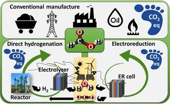
1. Introduction
2. Methodology
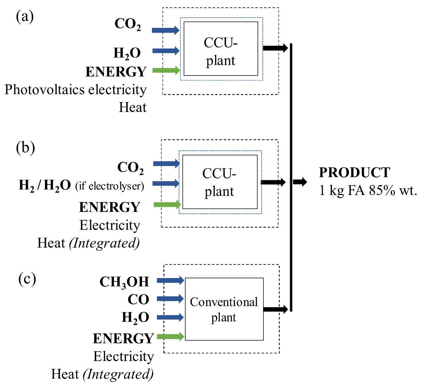
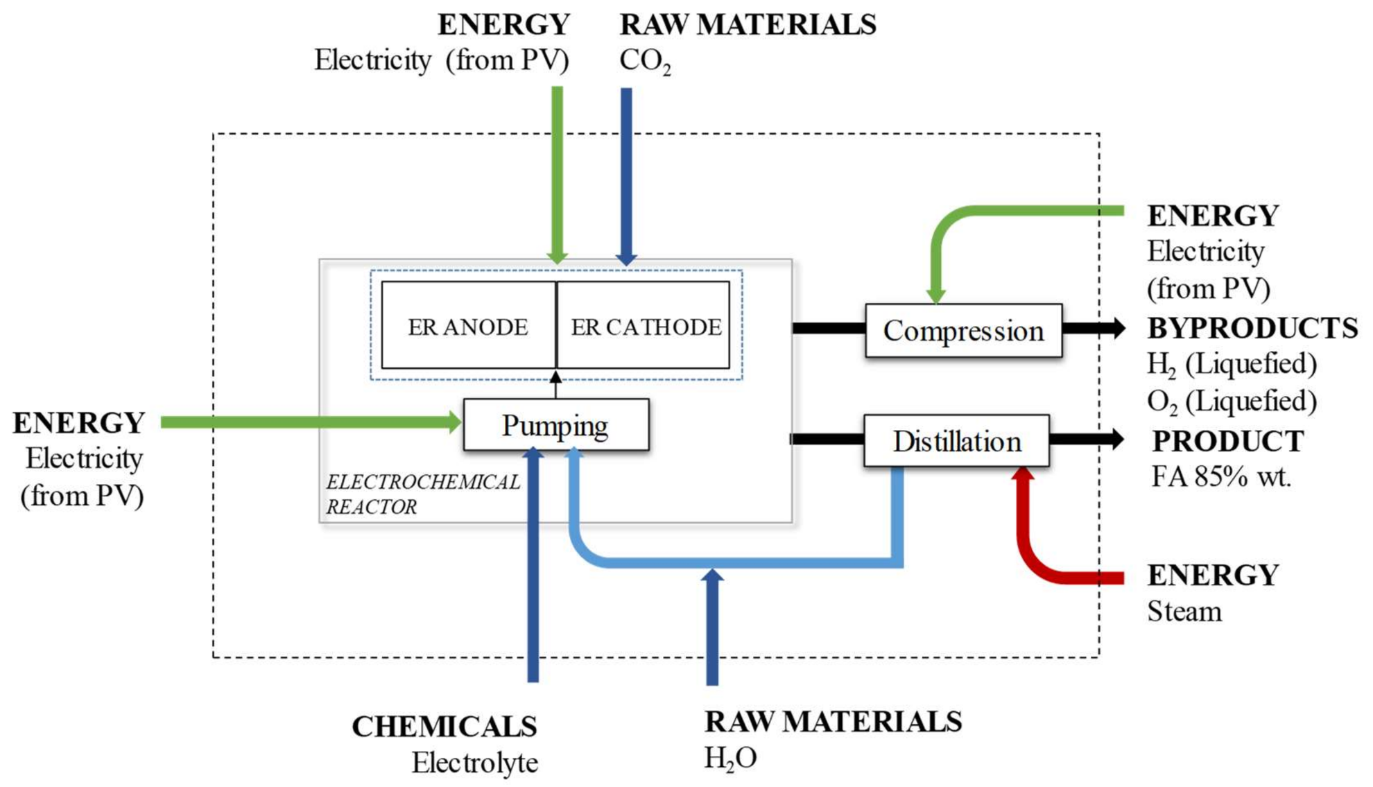
2.1. Alternative Based on Electrochemical Reduction CO2
- A CO2 valorisation plant is in the same site of the CO2 source (no transport is required).
- The feed of CO2 to the plant is assumed to be pure and with a suitable pressure for the ER process.
- The feed of CO2 to the plant is assumed to be free of environmental burdens. The feedstock CO2 sourced to the plant is for free, so 100% of the burdens are allocated to the product that directly releases the CO2, e.g., electricity forms a coal-fired power plant.
- The vapour steam needed for FA purification exists in dry saturated conditions.
- Electrolytes used in the ER process can be perfectly separated and they are considered to be avoided products.
- The lifetimes of the electrode materials and catalysts are long enough to neglect their carbon footprint.
2.2. Alternative Based on Homogeneous Catalysts of CO2 and H2 (AJCR)
2.3. Conventional Production of Formic Acid (ACONV)
3. Results and Discussions
3.1. Life Cycle Inventory of the Selected Alternatives and the Conventional Production Process
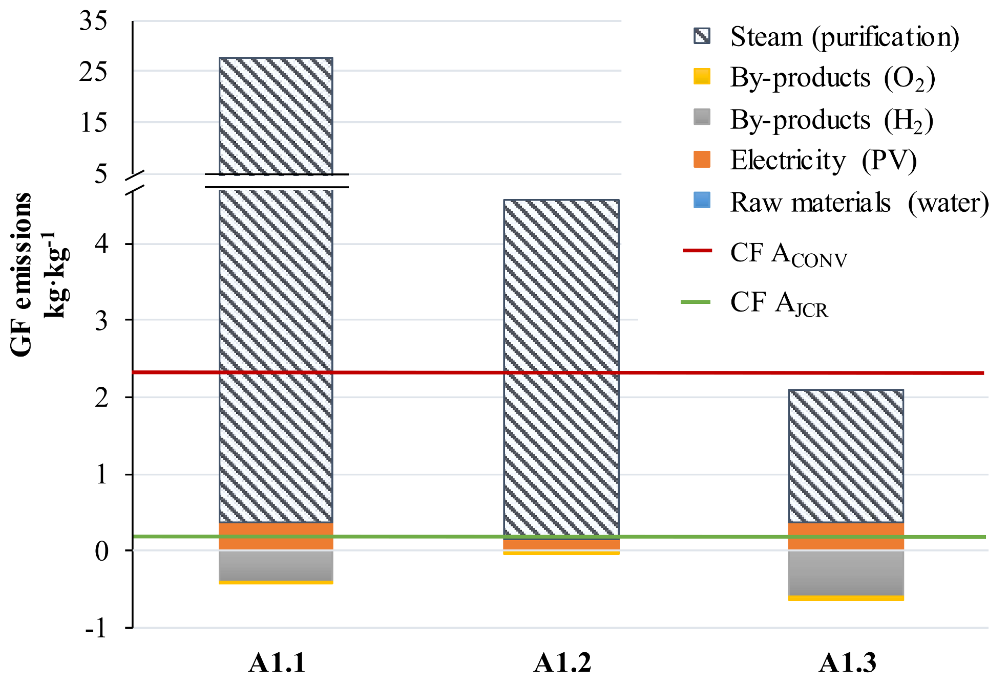
3.2. Carbon Footprint of the Selected Alternatives
3.3. Remaining Challenges
4. Conclusions
Author Contributions
Funding
Acknowledgments
Conflicts of Interest
References
- Grasemann, M.; Laurenczy, G. Formic acid as a hydrogen source—Recent developments and future trends. Energy Environ. Sci. 2012, 5, 8171–8181. [Google Scholar] [CrossRef]
- Hietala, J.; Vouri, A.; Pekka, J.; Ilkka, P.; Reutemann, W.; Heinz, K. Formic Acid. In Ullmann’s Encyclopedia of Industrial Chemistry; Wiley-VCH: Weinheim, Germany, 2000; pp. 1–22. ISBN 9783527306732. [Google Scholar]
- Arvola, J. Reducing Industrial Use of Fossil Raw Materials: Techno-Economic Assessment of Relevant Cases in Northern Finland; University of Oulu: Oulu, Finland, 2011; ISBN 9789514296888. [Google Scholar]
- Sharma, S.; Patle, D.S.; Gadhamsetti, A.P.; Pandit, S.; Manca, D.; Nirmala, G.S. Intensification and performance assessment of the formic acid production process through a dividing wall reactive distillation column with vapor recompression. Chem. Eng. Process. Process Intensif. 2018, 123, 204–213. [Google Scholar] [CrossRef]
- United Nations Framework Convention on Climate Change (UNFCCC). The Paris Agreement. Available online: http://unfccc.int/paris_agreement/items/9485.php (accessed on 31 October 2017).
- Pérez-Fortes, M.; Schöneberger, J.C.; Boulamanti, A.; Harrison, G.; Tzimas, E. Formic acid synthesis using CO2 as raw material: Techno-economic and environmental evaluation and market potential. Int. J. Hydrog. Energy 2016, 41, 16444–16462. [Google Scholar] [CrossRef]
- Pérez-Fortes, M.; Tzimas, E. Techno-Economic and Environmental Evaluation of CO2 Utilisation for Fuel Production—Synthesis of Methanol and Formic Acid; Publications Office of the European Union: Luxembourg, 2016. [Google Scholar] [CrossRef]
- Wang, W.-H.; Himeda, Y.; Muckerman, J.T.; Manbeck, G.F.; Fujita, E. CO2 Hydrogenation to Formate and Methanol as an Alternative to Photo- and Electrochemical CO2 Reduction. Chem. Rev. 2015, 115, 12936–12973. [Google Scholar] [CrossRef] [PubMed]
- Maru, M.S.; Ram, S.; Shukla, R.S.; Noor-ul, H.K. Ruthenium-hydrotalcite (Ru-HT) as an effective heterogeneous catalyst for the selective hydrogenation of CO2 to formic acid. Mol. Catal. 2018, 446, 23–30. [Google Scholar] [CrossRef]
- Hariyanandam, G.G.; Hyun, D.; Natarajan, P.; Jung, K.-D.; Yoon, S. An effective heterogeneous Ir(III) catalyst, immobilized on a heptazine-based organic framework, for the hydrogenation of CO2 to formate. Catal. Today 2016, 265, 52–55. [Google Scholar] [CrossRef]
- Yang, Z.-Z.; Zhang, H.; Yu, B.; Zhao, Y.; Ji, G.; Liu, Z. A Troger’s base-derived microporous organic polymer: Design and applications in CO2/H2 capture and hydrogenation of CO2 to formic acid. Chem. Commun. 2015, 51, 1271–1274. [Google Scholar] [CrossRef] [PubMed]
- Yan, N.; Philippot, K. Transformation of CO2 by using nanoscale metal catalysts: Cases studies on the formation of formic acid and dimethylether. Curr. Opin. Chem. Eng. 2018, 20, 86–92. [Google Scholar] [CrossRef]
- Suzuki, T.M.; Takayama, T.; Sato, S.; Iwase, A.; Kudo, A.; Morikawa, T. Enhancement of CO2 reduction activity under visible light irradiation over Zn-based metal sulfides by combination with Ru-complex catalysts. Appl. Catal. B Environ. 2018, 224, 572–578. [Google Scholar] [CrossRef]
- Yang, H.; Kaczur, J.J.; Sajjad, S.D.; Masel, R.I. Electrochemical conversion of CO2 to formic acid utilizing SustainionTM membranes. J. CO2 Util. 2017, 20, 208–217. [Google Scholar] [CrossRef]
- Del Castillo, A.; Alvarez-Guerra, M.; Solla-Gullón, J.; Sáez, A.; Montiel, V.; Irabien, A. Sn nanoparticles on gas diffusion electrodes: Synthesis, characterization and use for continuous CO2 electroreduction to formate. J. CO2 Util. 2017, 18, 222–228. [Google Scholar] [CrossRef]
- Ganesh, I. Electrochemical conversion of carbon dioxide into renewable fuel chemicals—The role of nanomaterials and the commercialization. Renew. Sustain. Energy Rev. 2016, 59, 1269–1297. [Google Scholar] [CrossRef]
- Kauffman, D.R.; Thakkar, J.; Siva, R.; Matranga, C.; Ohodnicki, P.R.; Zeng, C.; Jin, R. Efficient Electrochemical CO2 Conversion Powered by Renewable Energy. ACS Appl. Mater. Interfaces 2015, 7, 15626–15632. [Google Scholar] [CrossRef] [PubMed]
- Kondratenko, E.V.; Mul, G.; Baltrusaitis, J.; Larrazábal, G.O.; Pérez-Ramírez, J. Status and perspectives of CO2 conversion into fuels and chemicals by catalytic, photocatalytic and electrocatalytic processes. Energy Environ. Sci. 2013, 6, 3112–3135. [Google Scholar] [CrossRef]
- Jhong, H.R.M.; Ma, S.; Kenis, P.J. Electrochemical conversion of CO2 to useful chemicals: Current status, remaining challenges, and future opportunities. Curr. Opin. Chem. Eng. 2013, 2, 191–199. [Google Scholar] [CrossRef]
- Feaster, J.T.; Shi, C.; Cave, E.R.; Hatsukade, T.; Abram, D.N.; Kuhl, K.P.; Hahn, C.; Nørskov, J.K.; Jaramillo, T.F. Understanding Selectivity for the Electrochemical Reduction of Carbon Dioxide to Formic Acid and Carbon Monoxide on Metal Electrodes. ACS Catal. 2017, 7, 4822–4827. [Google Scholar] [CrossRef]
- Spurgeon, J.; KUMAR, B. A comparative technoeconomic analysis of pathways for commercial electrochemical CO2 reduction to liquid products. Energy Environ. Sci. 2018. [Google Scholar] [CrossRef]
- The Royal Society. The Potential and Limitations of Using Carbon Dioxide. 2017. Available online: www.royalsociety.org/low-carbon-energy-programme (accessed on 22 May 2018).
- Von der Assen, N.; Jung, J.; Bardow, A. Life-Cycle Assessment of Carbon Dioxide Capture and Utilization: Avoiding the Pitfalls. Energy Environ. Sci. 2013, 6, 2721–2734. [Google Scholar] [CrossRef]
- Von der Assen, N.; Voll, P.; Peters, M.; Bardow, A. Life cycle assessment of CO2 capture and utilization: A tutorial review. Chem. Soc. Rev. 2014, 43, 7982–7994. [Google Scholar] [CrossRef] [PubMed]
- Cuéllar-Franca, R.M.; Azapagic, A. Carbon capture, storage and utilisation technologies: A critical analysis and comparison of their life cycle environmental impacts. J. CO2 Util. 2015, 9, 82–102. [Google Scholar] [CrossRef]
- Dominguez-Ramos, A.; Singh, B.; Zhang, X.; Hertwich, E.G.; Irabien, A. Global warming footprint of the electrochemical reduction of carbon dioxide to formate. J. Clean. Prod. 2015, 104, 148–155. [Google Scholar] [CrossRef]
- Swiss Centre for Life Cycle Inventories. The Ecoinvent Database Version 3. Available online: http://www.ecoinvent.org (accessed on 22 May 2018).
- GaBi v8 LCA Software-System and Database for Life Cycle Engineering. Available online: http://www.gabi-software.com/hongkong/databases/ (accessed on 2 June 2018).
- Li, H.; Oloman, C. Development of a continuous reactor for the electro-reduction of carbon dioxide to formate—Part 1: Process variables. J. Appl. Electrochem. 2006, 36, 1105–1115. [Google Scholar] [CrossRef]
- Oloman, C.; Li, H. Electrochemical processing of carbon dioxide. ChemSusChem 2008, 1, 385–391. [Google Scholar] [CrossRef] [PubMed]
- Dominguez-Ramos, A.; Held, M.; Aldaco, R.; Fischer, M.; Irabien, A. Prospective CO2 emissions from energy supplying systems: Photovoltaic systems and conventional grid within Spanish frame conditions. Int. J. Life Cycle Assess. 2010, 15, 557–566. [Google Scholar] [CrossRef]
- International Energy Agency (IEA). Statistics Manual. Available online: https://www.iea.org (accessed on 17 January 2018).
- Endrödi, B.; Bencsik, G.; Darvas, F.; Jones, R.; Rajeshwar, K.; Janáky, C. Continuous-flow electroreduction of carbon dioxide. Prog. Energy Combust. Sci. 2017, 62, 133–154. [Google Scholar] [CrossRef]
- Dai, L.; Xue, Y.; Qu, L.; Choi, H.J.; Baek, J.B. Metal-Free Catalysts for Oxygen Reduction Reaction. Chem. Rev. 2015, 115, 4823–4892. [Google Scholar] [CrossRef] [PubMed]
- Hoffman, Z.B.; Gray, T.S.; Moraveck, K.B.; Gunnoe, T.B.; Zangari, G. The Electrochemical Reduction of Carbon Dioxide to Syngas and Formate at Dendritic Copper-Indium Electrocatalysts. ACS Catal. 2017, 7, 5381–5390. [Google Scholar] [CrossRef]
- Aeshala, L.M.; Rahman, S.U.; Verma, A. Effect of solid polymer electrolyte on electrochemical reduction of CO2. Sep. Purif. Technol. 2012, 94, 131–137. [Google Scholar] [CrossRef]


| Cathodic Reaction | Anodic Reaction |
|---|---|
| CO2 + H2O + 2e− → HCOO− + OH− | H2O → 2H+ + 2e− + 1/2 O2 |
| 2H2O + 2e− → H2 + 2 OH− | |
| Overall reaction | |
| CO2 + 2H2O → HCOOH + O2 + H2 | |
| UNITS | A1.1 [15] | A1.2 [14] | A1.3 [14] | |
|---|---|---|---|---|
| Cathode | Sn NPs (Sn/C-GDEs) | Sn NPs (Sn/C-GDEs) | Sn NPs (Sn/C-GDEs) | |
| Anode | DSA/O2 (Ir-MMO on Pt) | IrO2 on Toray paper | IrO2 on Toray paper | |
| Cation membrane material | Dupont Nafion 324 | Dupont Nafion 324 | ||
| Anion membrane material | Dioxide Materials SustanionTM | Dioxide Materials SustanionTM | ||
| Current density, i | mA·cm−2 | 200 | 140 | 140 |
| Electrolyte flowrate to geometric projected cathodic area, Q/A | mL·min−1·cm−2 (10−3) | 70.0 | 6.00 | 6.00 |
| Geometric projected cathodic area, A | cm2 | 10.0 | 5.00 | 5.00 |
| Faradaic current efficiency, FE | % | 42.3 | 94.0 | 32.0 |
| FA reaction rate, rFA | mmol·m−2·s−1 | 4.38 | 2.22 | 4.63 |
| Overall cell voltage, Ecell | V | 4.30 | 3.28 | 3.28 |
| Concentration of FA, [FA] | % wt. | 1.68 | 10.0 | 20.5 |
| Mode of operation | Single pass | Single pass | Recirculated |
| AER | AJRC | ACONV | ||||
|---|---|---|---|---|---|---|
| UNITS | A1.1 | A1.2 | A1.3 | |||
| Electrode/Catalyst | ||||||
| TOTAL | kg (10−6) | 1.30 | 9.92 | 14.9 | 3.75 | 15.60 |
| Raw materials | ||||||
| CO2 | kg | 0.95 | 0.96 | 0.96 | 0.83 | - |
| H2O | kg | 1.10 | 0.59 | 1.41 | 0.56 | 0.60 |
| CO | kg | - | - | - | - | 0.61 |
| CH3OH | kg | - | - | - | - | 0.04 |
| Products | ||||||
| HCOOH | kg | 1.00 | 1.00 | 1.00 | 1.00 | 1.00 |
| H2O | kg | 0.18 | 0.18 | 0.18 | 0.06 | 0.18 |
| By-products | ||||||
| H2 | kg (10−3) | 59.00 | 3.00 | 92.00 | −0.06 | - |
| O2 | kg | 0.82 | 0.37 | 1.09 | 0.48 | - |
| Energy | ||||||
| Electricity | ||||||
| ER | kWh | 11.80 | 4.59 | 11.93 | - | - |
| Pump | kWh (10−3) | 7.35 | 1.24 | 0.63 | - | - |
| Compression | kWh | 0.15 | 0.04 | 0.11 | - | - |
| TOTAL | 11.80 | 4.59 | 11.90 | 4.07 | 0.29 | |
| Heat demand | ||||||
| Steam | MJ | 401.00 | 65.18 | 25.67 | 10.03 | 22.77 |
| Raw Materials Consumption | ||||
|---|---|---|---|---|
| Unit | ACONV [27] | A1.3 | AJCR | |
| Heavy fuel oil | kg | 0.405 | ||
| Natural gas (heat) | kg | 0.273 | 0.423 | 0.166 |
| Natural gas at high pressure * | kg | 1.250 | ||
| Hydrogen | kg | 0.060 ** | ||
© 2018 by the authors. Licensee MDPI, Basel, Switzerland. This article is an open access article distributed under the terms and conditions of the Creative Commons Attribution (CC BY) license (http://creativecommons.org/licenses/by/4.0/).
Share and Cite
Rumayor, M.; Dominguez-Ramos, A.; Irabien, A. Formic Acid Manufacture: Carbon Dioxide Utilization Alternatives. Appl. Sci. 2018, 8, 914. https://doi.org/10.3390/app8060914
Rumayor M, Dominguez-Ramos A, Irabien A. Formic Acid Manufacture: Carbon Dioxide Utilization Alternatives. Applied Sciences. 2018; 8(6):914. https://doi.org/10.3390/app8060914
Chicago/Turabian StyleRumayor, Marta, Antonio Dominguez-Ramos, and Angel Irabien. 2018. "Formic Acid Manufacture: Carbon Dioxide Utilization Alternatives" Applied Sciences 8, no. 6: 914. https://doi.org/10.3390/app8060914
APA StyleRumayor, M., Dominguez-Ramos, A., & Irabien, A. (2018). Formic Acid Manufacture: Carbon Dioxide Utilization Alternatives. Applied Sciences, 8(6), 914. https://doi.org/10.3390/app8060914