Article

Virtual Synchronous Motor Based-Control of a Three-Phase Electric Vehicle Off-Board Charger for Providing Fast-Charging Service

1
Key Laboratory of Distributed Energy Storage and Micro-Grid of Hebei Province, North China Electric Power University, Baoding 071003, China
2
Electric Power Research Institute of State Grid Liaoning Electric Power Co. Ltd., Shenyang 110006, China
3
China Electric Power Research Institute (CEPRI), Beijing 100192, China
*
Author to whom correspondence should be addressed.
Appl. Sci. 2018, 8(6), 856; https://doi.org/10.3390/app8060856
Submission received: 11 April 2018 / Revised: 18 May 2018 / Accepted: 18 May 2018 / Published: 23 May 2018
(This article belongs to the Special Issue Electric Vehicle Charging)

Abstract

:
This study introduces a three-phase virtual synchronous motor (VSM) control and its possible application for providing fast-charging service from off-board chargers of electric vehicles (EVs). The main circuit of the off-board charger consists of a three-phase voltage source PWM rectifier (VSR) and a resonant LLC zero-voltage-switching converter. In the proposed control approach, VSM-controlled pre-stage VSR emulates the external characteristics of a synchronous motor (SM), simultaneously, droop control based on charging mode in the VSM can satisfy the demand of the EVs constant-current fast-charging; The post-stage DC–DC converter is responsible for stabilizing the DC bus voltage. The feature of this control strategy is that VSM and fast charging control are implemented by the pre-stage converter, which has better coordination. In the MATLAB, the equivalent synchronous grid of the distribution network supplies to the power battery through the off-board charger, and the effectiveness of the presented control is demonstrated by typical working conditions.

1. Introduction

The energy crisis [1] and environmental pollution [2] are the main reasons for leveraging the large-scale adoption of electric vehicles (EVs). The Chinese government has energetically supported the EV’s establishment. In April 2012, the ‘Energy Conservation and New Energy Vehicle Industry Development Plan (2012–2020)’ formulated by the State Council pointed out that “in 2020, pure electric vehicles and plug-in-hybrid electric vehicles will be industrialized, and their cumulative production and sales will exceed 5 million.” The rapid growth of EVs has increased their permeability in the distribution network.
The charging mode of EVs is mainly divided into slow charging [3] and fast charging [4]. Slow charging is appropriate for low-power on-board chargers [5], the charging time of which is customarily in excess of 6 h. On the contrary, fast charging is generally utilized to high-power off-board chargers, which is an attractive option over slow charging due to its potential to fully charge the EV in less than 1 h [6]. Thus, fast charging is favored by consumers thanks to economize on time [7].
However, for the power system, EVs are nonlinear loads whose frequent input and exit will provoke a negative impact on the power quality of the distribution network [8,9,10]. To alleviate the above problems, loads-virtual synchronous motor (VSM) technology has attracted more attention due to its ability to improve stability of frequency and voltage. On account of this superiority, some scholars put forward the application of VSM to the EV chargers [11,12,13,14]. Indeed, VSM can provide inertia and damping to suppress rapid changes in voltage and frequency during transients. Furthermore, EVs autonomously participate in the primary regulation to achieve responsive interaction with the grid in the steady case.
As a promising control approach, the VSM has been intensively investigated since it can resolve the EVs integration problems most flexibly. The provision of ancillary services from VSM-controlled single-phase chargers has previously been discussed [11,12]. However, with widespread concern of fast charging, VSM-based control has gradually concentrated on three-phase power converters. If a VSM implementation designed for single-phase systems is directly applied to a three-phase converter, the control structure will be further complicated. Aiming at the three-phase EV charger composed of two-stage topology, the VSM construction method is distinct with sing-stage VSC in [12], which can take graded-control in the pre-stage AC/DC and post-stage DC/DC in accordance with its control objective [13]. In addition, if three-phase VSM continue to employ proportional resonant (PR) controller which is used in single-phase control, this implies that six PR controllers will be needed for achieving double closed-loop control. Nevertheless, this can be avoided by leading into vector control based on three-phase instantaneous reactive power theory, as mentioned in [13,14].
The proposal for actualizing three-phase VSM has been proposed in [13]. On this basis, [14] extends to VSM control based on fast charging mode, in which the pre-stage converter implements VSM function and maintains the DC bus voltage stability, and the post-stage circuit realizes constant-voltage charging by means of double closed-loop control. However, since resistance is leveraged for emulating the power battery, the charging mode is not clear, which can be considered as constant-voltage charging due to invariance of resistance voltage. But fast charging adopts constant-current/power mode in general. Additionally, simulation results can be incapable of reflecting the primary frequency regulation characteristic of VSM owing to the application of ideal power grid model.
Thus, in view of the deficiencies in [14], following the graded-control thought and the vector control based on three-phase instantaneous reactive power theory [13,14], this paper presents a novel VSM control scheme suitable for the fast charging of the off-board chargers. VSM-controlled pre-stage PWM rectifier is provided with inertia, damping and primary regulation capabilities. Importantly, in the VSM strategy, droop control based on charging mode allows off-board charger to operate with constant-current fast charging. The post-stage LLC converter contributes to the stability of the DC bus voltage. The control targets of the two stage circuits are different and the division of labor is clear. Using equivalent synchronous gird can validate the primary regulation behaviors of VSM and the actual dynamic features of the distribution network. The intended performance of the proposed method and the system was verified through simulation.

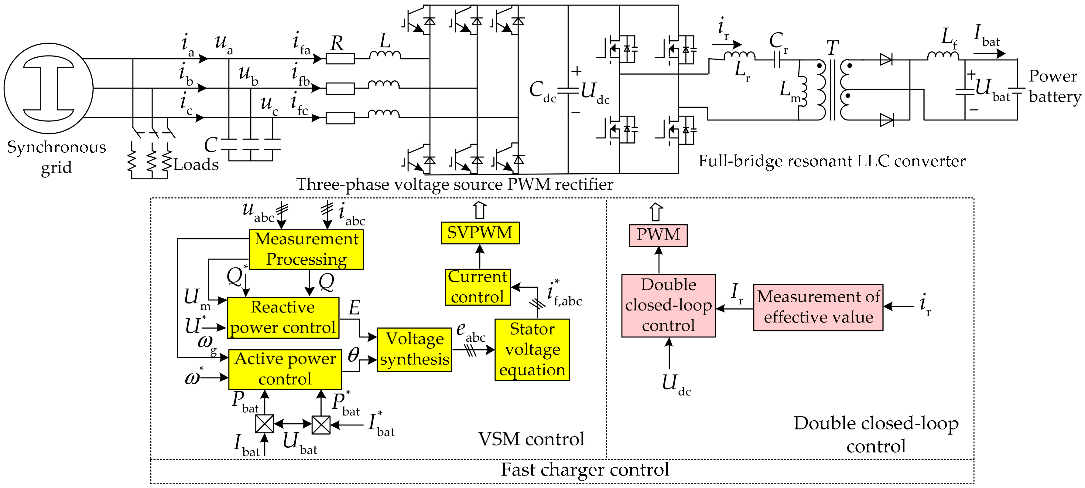
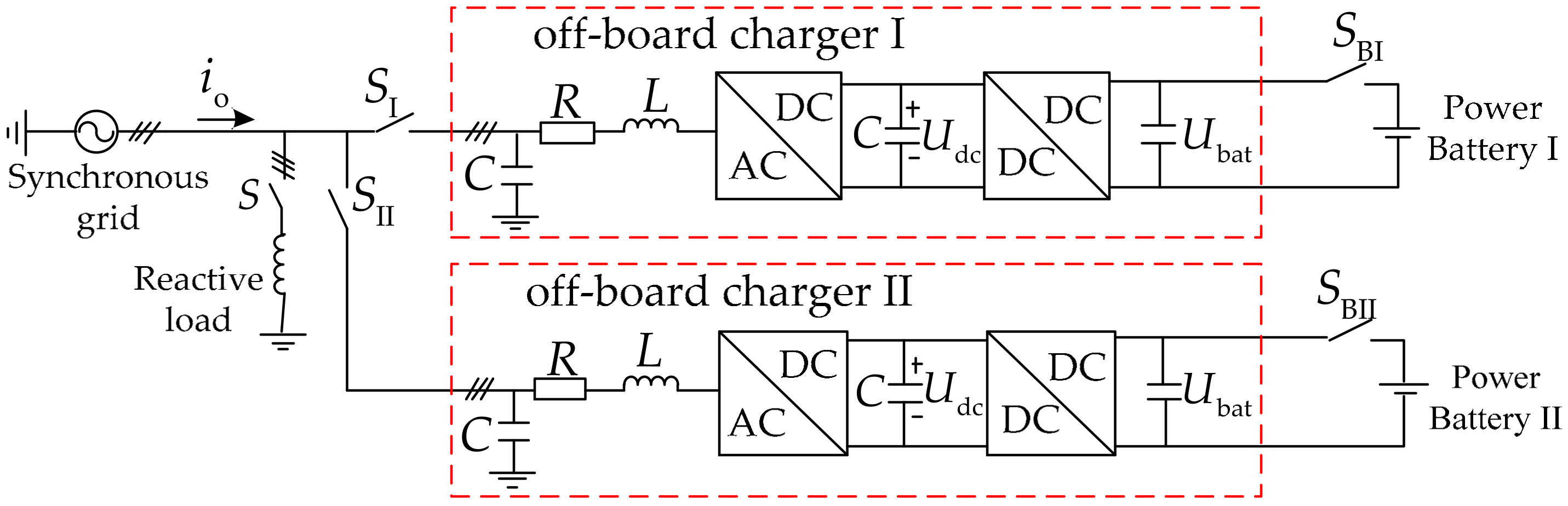
2. Overview of System Configuration

For the investigated case, the main circuit of the off-board charger comprised of a full-bridge resonant LLC converter and a three-phase voltage source PWM rectifier is interfaced with the synchronous grid through LC filter, as indicated in Figure 1.
The fast charger control strategy is split into two major parts, which are the pre-stage VSM control and post-stage double closed-loop control.
  • VSM control not only ensures inertia and damping emulation and frequency support as well as voltage control, but also make the off-board charger provide the constant-current fast charging service for the EV’s power battery.
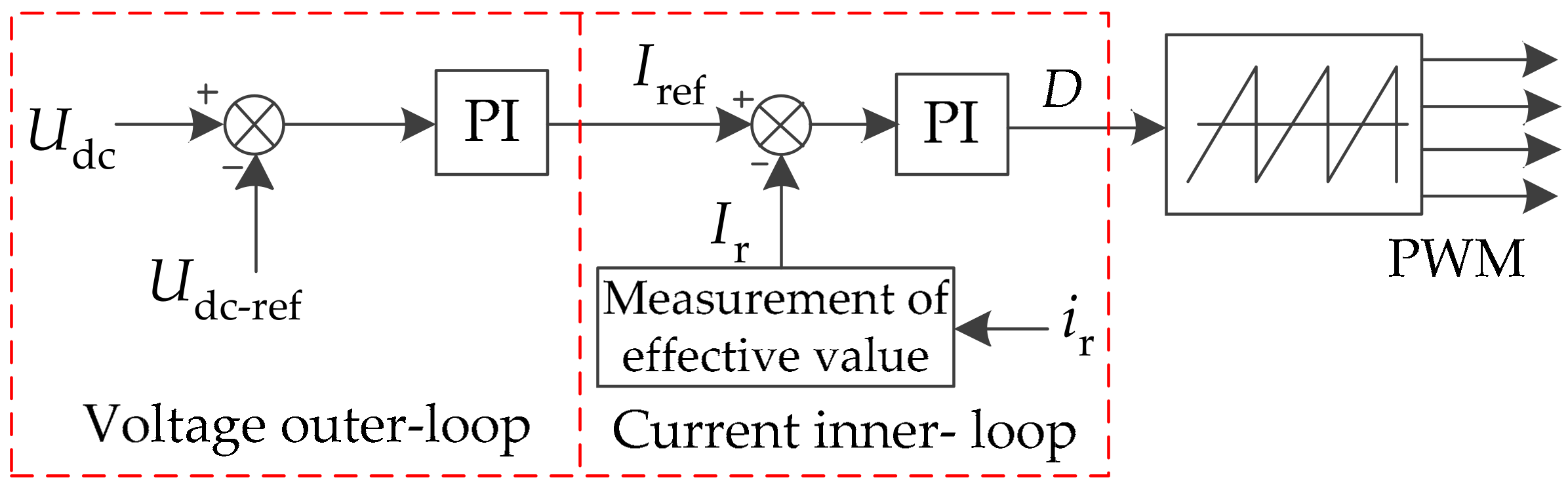
  • Double closed-loop control is in charge of stabilizing the DC bus voltage Udc.
Figure 1 only shows an overview of the overall control scheme, so the implementation of these control functions is described in detail in the following sections.

3. Off-board Charger Control
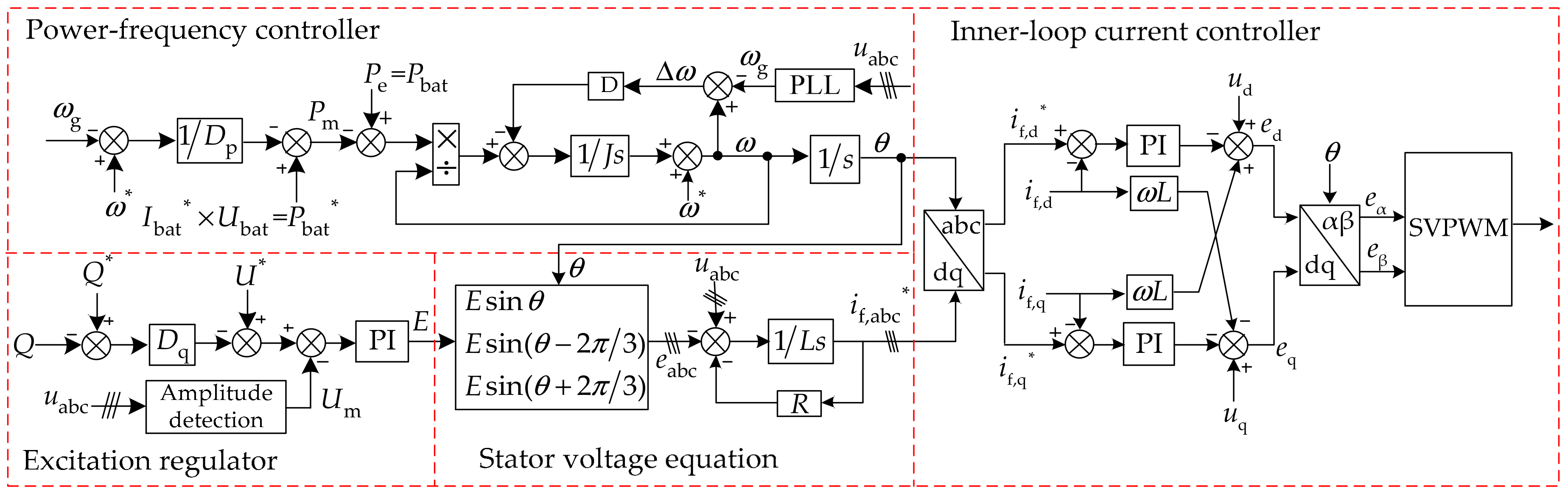
3.1. VSM Control

In this section, an elaborate effectuation of the presented VSM, including power-frequency controller, excitation regulator, stator voltage equation and inner-loop current controller, is shown in Figure 2. Subsequent subsections will address how to derive such VSM control.

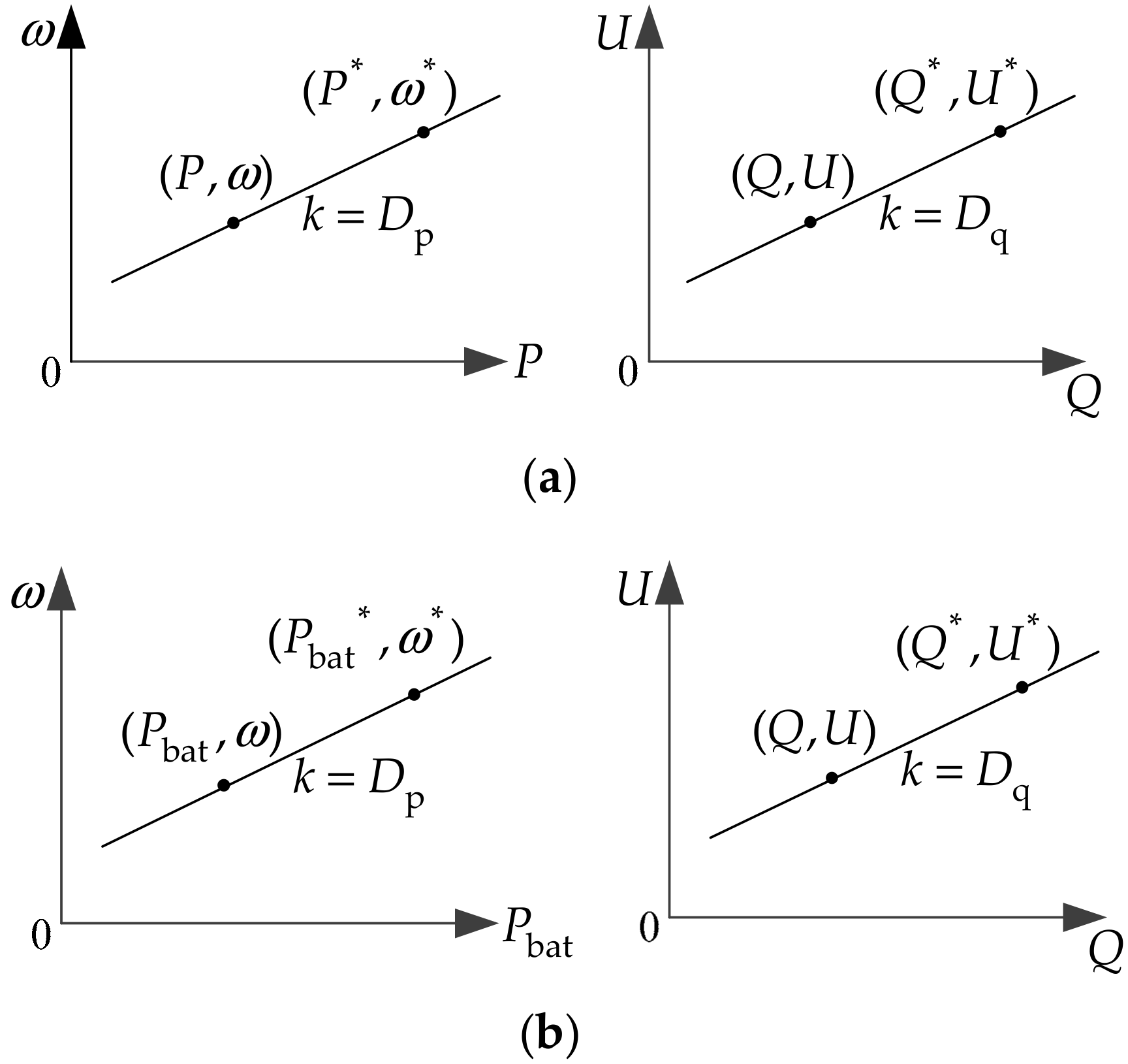
3.1.1. Droop Control Based on Charging Mode

Primary frequency/voltage regulation is a fundamental feature of the VSM control. In previous related studies [15,16], the active power P and reactive power Q of the rectifier are leveraged to achieve the droop control, and the P-ω and Q-U curves is shown in Figure 3a. The above-mentioned commonly-used droop control only incarnates the primary regulation characteristics of VSM, but it cannot bring about the proposed fast charging function. Thus, in order to accomplish the above goal, this paper presents the droop control based on charging mode, whose Pbat-ω and Q-U curves is expressed in Figure 3b, in which Q-U curve remains invariable while the charging power Pbat substitutes the active power of the rectifier P.
P and Pbat represent the active power of the rectifier and charging power of the power battery, respectively. ω is the angular frequency. Q and U are the reactive power and the AC voltage amplitude of the rectifier. Dp and Dq are the frequency and voltage droop coefficients. Reference values for any given signal x are indicated by a superscript asterisk as x*.
According to the droop curves based on the charging mode in Figure 3b, the droop relations of the Pbat-ω and Q-U are given by
D p = ω * ω P bat * P bat                 ( D p > 0 )
D q = U * U Q * Q                 ( D q > 0 )
Equations (1) and (2) are transformed to
ω = ω * D p ( P bat * P bat )       ( D p > 0 )
U = U * D q ( Q * Q )       ( D q > 0 )
To integrate with the constant-current charging, we alter the setting form of Pbat* in Equation (3), as shown in Equation (5).
P bat * = U bat × I bat *
Battery Model is adopted in the system. Ubat is the feedback value of the real-time charging voltage of Battery, which changes with variation of state of charge (SOC) and charging current during the charging process. Ibat* is the charging current reference value. The product of Ubat and Ibat* constitutes the charging power reference Pbat*.
Since the unit of the battery capacity is Ah, which is the product of Charging current (A) and Time (h), i.e., Capacity (Ah) = Charging current (A) × Time (h), Charging current (A) is equal to the quotient of Capacity (Ah) and Time (h), i.e., Charging current (A) = Capacity (Ah)/Time (h). The fast charging time is usually less than an hour, i.e., Time (h) < 1 h, so if the constant-current fast charging intends to be fulfilled, we should assign that the set value of the charging current Ibat* is greater than the value of the power battery capacity, i.e., I bat *   >   | Capacity   ( Ah ) | .
Thus, in accordance with the above analysis, the active droop relation combined with constant-current fast charging is obtained in Equation (6).
ω = ω * D p ( I bat * × U bat P bat ) ( D p > 0 )
The actual angular frequency is acquired through a PLL measurement in engineering control, so ω is expressed by ωg. Integrating the relationships of Equation (4), Equation (6) and ωg, the new primary regulation features of the proposed VSM are shown by Equation (7).
{ ω g = ω * D p ( I bat * × U bat P bat ) U = U * D q ( Q * Q )
In conclusion, in the presented three-phase VSM, the droop control based on charging mode possesses two major contributions:
  • The rectifier is the capacity to take part in the primary regulation of the voltage and frequency in the case of steady state.
  • The off-board charger feeds the power battery in the way of constant-current fast charging.

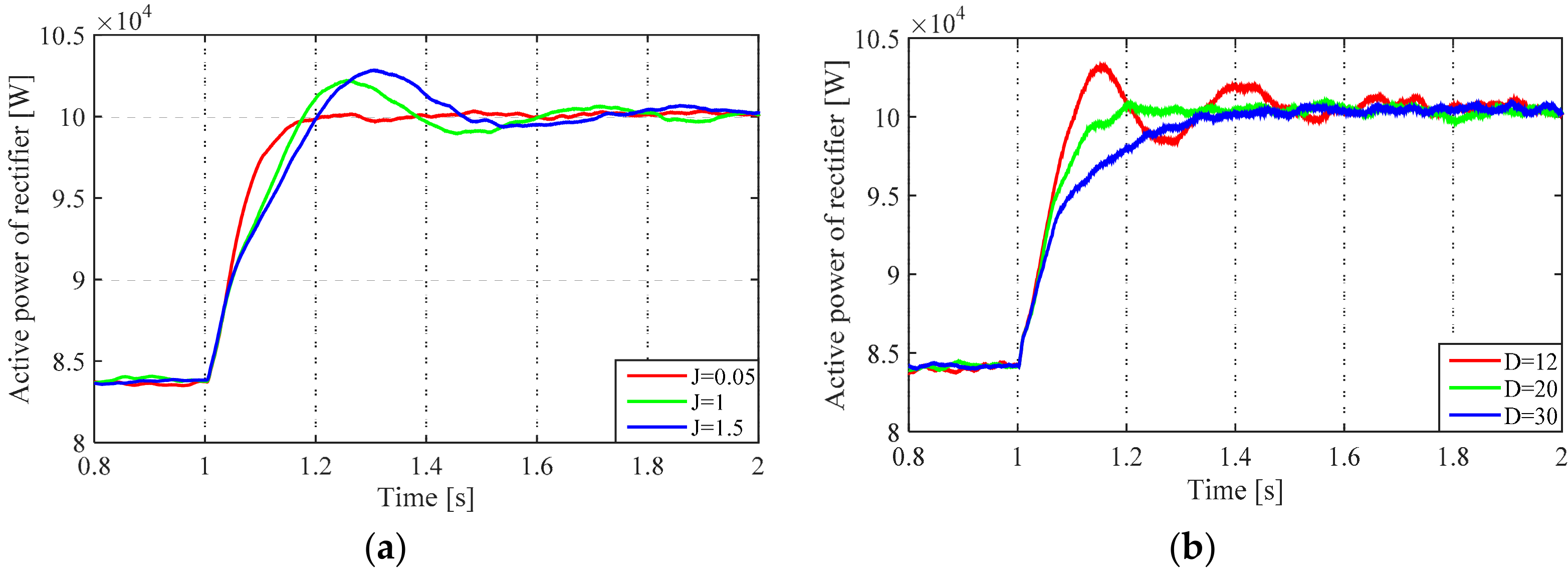
3.1.2. Behaviors of the Inertia and Damping

Another core objective of the VSM is to enable the rectifier externally exhibit the inertia and damping of the SM, which is generally indicated by a simplified classic second-order model of an SM. The VSM rotor equation of motion can be described by the equation below.
{ J d ( ω ω * ) d t = P e P m ω D ( ω ω g ) d θ d t = ω
where: the inertia is given by J; D represents the damping coefficient; Pe is the electromagnetic power; Pm is mechanical power; ω is electrical angular velocity of the VSM; ω* is the rated angular frequency; ωg is the grid angular frequency; θ is the power angle.
In order to connect the inertia and damping of the VSM (Equation (8)) with Pbat-ω droop control (Equation (7)) to comprise a power-frequency controller, there are two setting forms depending on whether losses are considered. If the efficiency of the conversion circuit is extremely high, the losses can be ignored. The relations are defined by Equation (9).
{ P m = I bat * × U bat ( ω * ω g ) / D p P e = P bat
If the efficiency is not neglected, assuming that we continue to use Equation (9), which will make the actual charging current slightly less than the set value, i.e., Ibat < Ibat*. Thus, to strictly let Ibat = Ibat*, Equation (9) is amended as follows.
{ P m = 1 η × ( I bat * × U bat ( ω * ω g ) / D p ) P e = P bat
In the Equation (10), η is the efficiency coefficient which varies with power, whose expression is η = Pbat/P. P is not only the rectifier power but also the input power of the off-board charger. Pbat represents the charging power of the power battery as well as the output power of the off-board charger.
Equations (9) and (10) signify that the mechanical power Pm is represented by the Pbat-ω droop control, and the electromagnetic power Pe is denoted by real-time charging power Pbat of the power battery.
In addition to the power-frequency controller, Figure 3 also includes the excitation regulator and the stator voltage equation. The excitation regulator contains a closed-loop control between the Q-U droop (Equation (4)) and the AC voltage amplitude Um of the rectifier. Electrical angle θ of the power controller and E of the excitation regulator synthesize the three-phase excitation electromotive force eabc through Equation (11).
e abc = [ E sin θ E sin ( θ 2 π / 3 ) E sin ( θ + 2 π / 3 ) ]
To enhance the stability and waveform quality of the VSM-based control system, the power outer-loop composed of the power-frequency controller and the excitation regulator requires to be combined with the inner-loop current controller by the stator voltage equation, which is illustrated by
u abc = e abc + R i abc + L d i abc d t
The inductor L and resistance R in the LC filter are invoked as the synchronous reactance and armature resistance of the stator electrical equation. The inner-loop current controller provides the modulation index for SPVWM which generates the pulse signals of the rectifier switching transistor. Thus, the studied VSM can support the virtual inertia and damping for the grid during transient operation.

3.2. Double Closed-Loop Control

The DC/DC converter in the off-board charger uses a full-bridge resonant LLC converter that is frequently used in practical applications. This converter not only actualizes the electrical isolation between the power battery and the grid, but also has the characteristics of high power transmission and high efficiency, which can meet the fast charging requirement of high-capacity electric vehicles [17,18]. The double closed-loop control which is shown in Figure 4 will be mainly relevant for ensuring the stability of the DC bus voltage Udc. The post-stage DC/DC converter does not directly regulate the charging power Pbat of the power battery, which is processed by pre-stage AC/DC converter.
It can be noticed from Figure 4 that the inner-loop current reference value Iref which is obtained by outer-loop voltage Udc control and the effective value Ir of resonant current emit the PWM modulated signals D through PI control. When the battery is charged, the full-bridge resonant LLC converter is in the step-down mode. Under such circumstances, the direction of the current flowing into the battery is positive, i.e., Ibat > 0, but Udc-refUdc < 0. Accordingly, the reference value of the inner-loop current is engendered by using UdcUdc-ref for PI control.

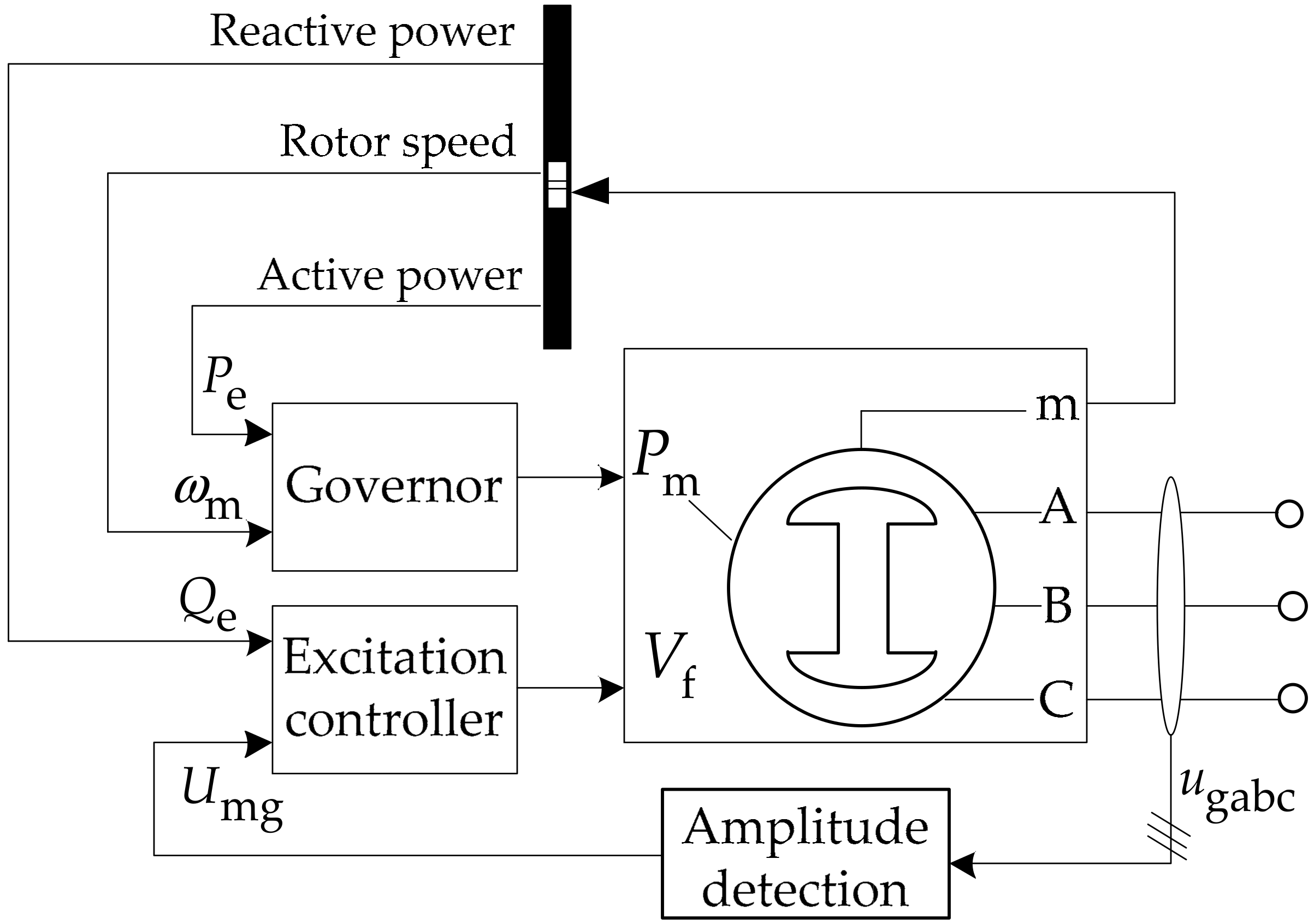
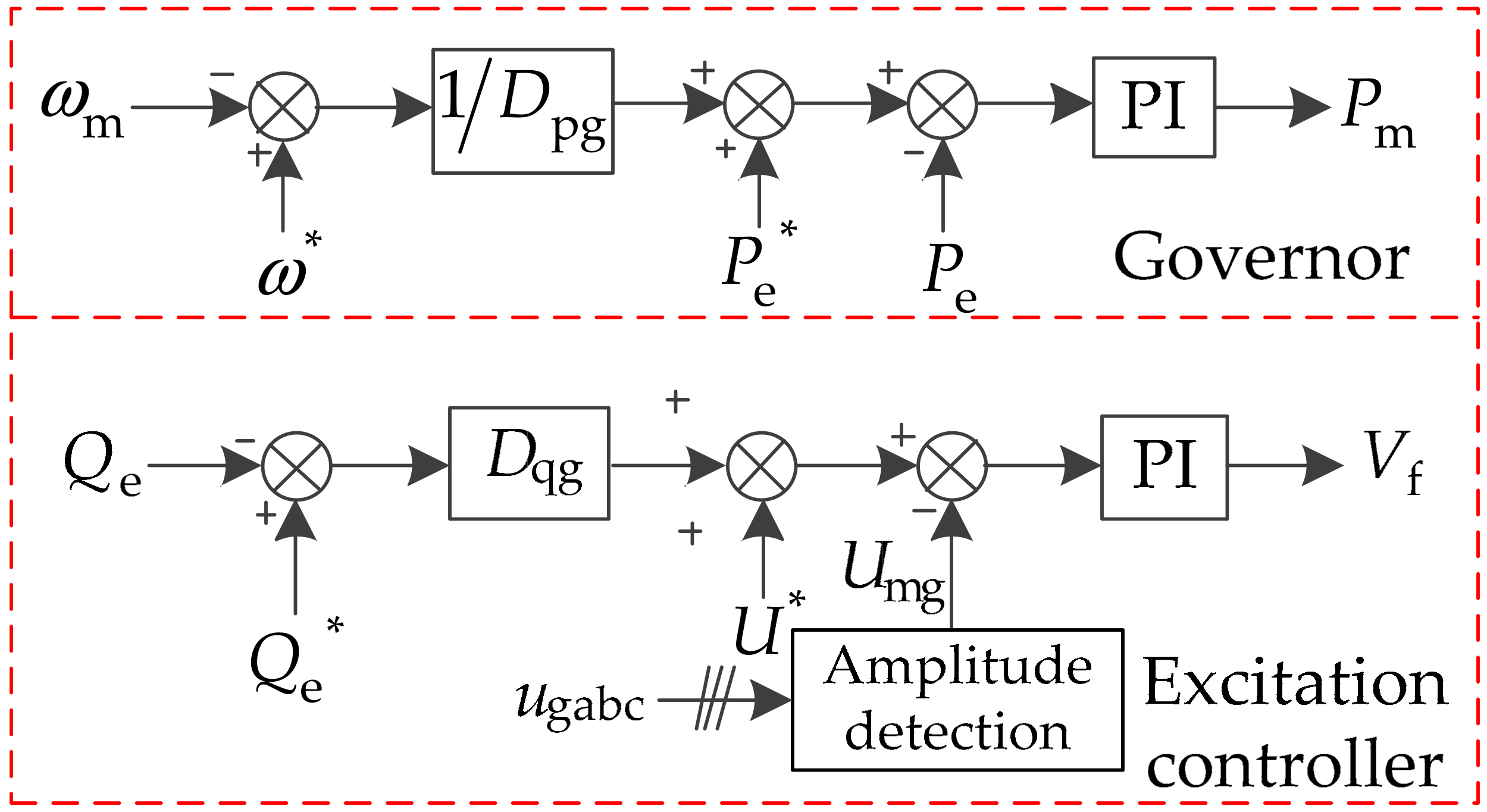
4. Synchronous Grid Control

In past related studies on the EV system connected into the power grid, the ideal grid model was widely used. In this case, the grid frequency keeps constant no matter how the loads changed. Since the impact of frequent input and exit of high-power charging loads on the grid frequency is planned to be examined, the ideal grid model is unsuitable for the research purpose. Thus, the equivalent synchronous grid model has been designed and shown in Figure 5. For this model, the equivalent synchronous grid constituted of the synchronous generator (SG) with primary regulation characteristics is the equivalent simulation of all the power supplies in the practical grid, whose capacity is equal to the sum of the capacities of all the power supplies.
Governor and excitation controller of the synchronous grid are designed according to the droop curves of the power generation, which can be seen in Figure 6. In the following control, Pe, Qe and ωm are output active power, output reactive power and rotor speed of the SG respectively. Dpg and Dqg are the droop coefficients of the synchronous grid. Umg is the SG actual output voltage ugabc amplitude.
In short, the synchronous grid not only displays the impact on frequency variations in the power system, but also is conductive to validate the primary frequency regulation characteristic of the VSM. Therefore, the synchronous grid is employed to emulate the actual distribution network, for ease of reading, which is abbreviated as the grid in the subsequent sections.

5. Verification

In this section, the basic functionalities of the proposed VSM and fast-charging ability of the off-board charger are investigated. First, the overall system model described in Figure 7 is established in MATLAB/Simulink. Then, contrasted with the traditional control scheme of the EV, the performance of the proposed control is validated.

5.1. Simulation Parameters

The main components parameters of the investigated system are reported in Table 1.
The integrated system model of the power battery connected to the synchronous grid by off-board chargers is built on the MATLAB/Simulink, as shown in Figure 7.
The synchronous grid adopts the control model presented in Figure 5 of Section 4. AC/DC and DC/DC converters are three-phase voltage source PWM rectifier and the full-bridge resonant LLC converter in Section 2, respectively. The power battery I/II are the Nickel-Metal Hydride battery.

5.2. Verification Process

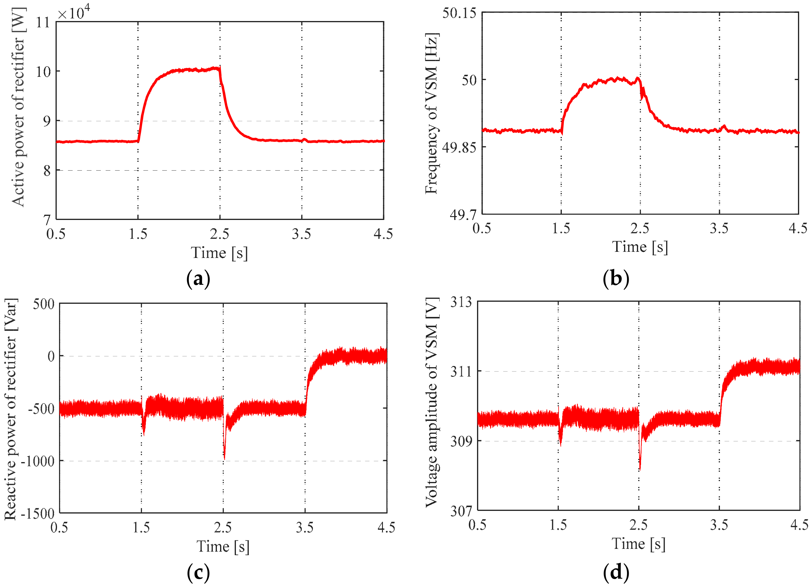
5.2.1. Verification of the Basic Functionalities of the Proposed VSM Control

For VSM-controlled off-board charger system, its inertia and damping characteristics as well as primary regulation abilities are required to be proved, whose validation results are in the following subsections.
(1) Verification of the Inertia and Damping Characteristics
Taking the off-board charger I as an example in Figure 7, three typical values of the inertia and damping are selected separately to observe the effects of different inertia and damping on the active power of the rectifier, which are J = 0.05, 1, 1.5 and D = 12, 20, 30, respectively. In the initial state, the grid sends power to the power battery I and the power battery II. Power battery II is out of service at 1 s. Figure 8 shows the waveforms of the rectifier’s active power varying with the inertia J and the damping D.
First, it is evident from Figure 8 that the proposed VSM introduces the inertia and damping characteristics of the synchronous motor into the control of the off-board charger in the transient process. Next, active power of the rectifier increases 8.4 kW to 10 kW due to the abrupt exit of the power battery II. For inertia, it can be observed from Figure 8a that it can restrain the sudden power change, but with the increase of inertia, dynamic response of the system slows down. Moreover, compared with J = 0.05, the active power starts to oscillate when J = 1, and oscillation amplitude of J = 1.5 is greater than J = 1. For damping, it can be noticed in Figure 8b that damping suppresses oscillations, where oscillation amplitude decrease in order with the increase of damping D, but overdamping will make the system take longer to reach steady state. Therefore, the abovementioned inertia and damping effects are consistent with the dynamic characteristics of the synchronous motor, and choosing the appropriate inertia and damping is of great significance to enhance the stability of the charging system.
(2) Verification of Primary Regulation
Similarly, regarding the off-board charger I in Figure 7 as a focus point, we verify the primary regulation of VSM whose simulation results are depicted in Figure 9. The simulation scenario is set as follows:
Before 1.5 s, the power grid supplies power to 1 kVar reactive load, power battery I and power battery II.
Off-board charger II is out of operation at 1.5 s and connects to the power grid again at 2.5 s.
1 kVar reactive load at the AC interface exits operation at 3.5 s.
It is worth noting that when the active power and reactive power fluctuates, the adjustment ratio of the grid and off-board charger I is set to 1:1. In addition, the active power of the off-board charger II is set to 30 kW.
From Figure 9a,c, according to the 1:1 adjustment ratio, except the power undertaken by the grid, the rectifier increases the absorption of 15 kW active power between 1.5 and 2.5 s, and the reactive power of rectifier changes from −500 Var to 0 Var due to the withdraw of the reactive load at 3.5 s. Meanwhile, we can see from Figure 9b,d that the frequency and voltage of the VSM are adjusted according to their droop characteristics. Therefore, in the steady state, the proposed VSM participates in the regulation of frequency and voltage when the charging load is frequently input and exit.

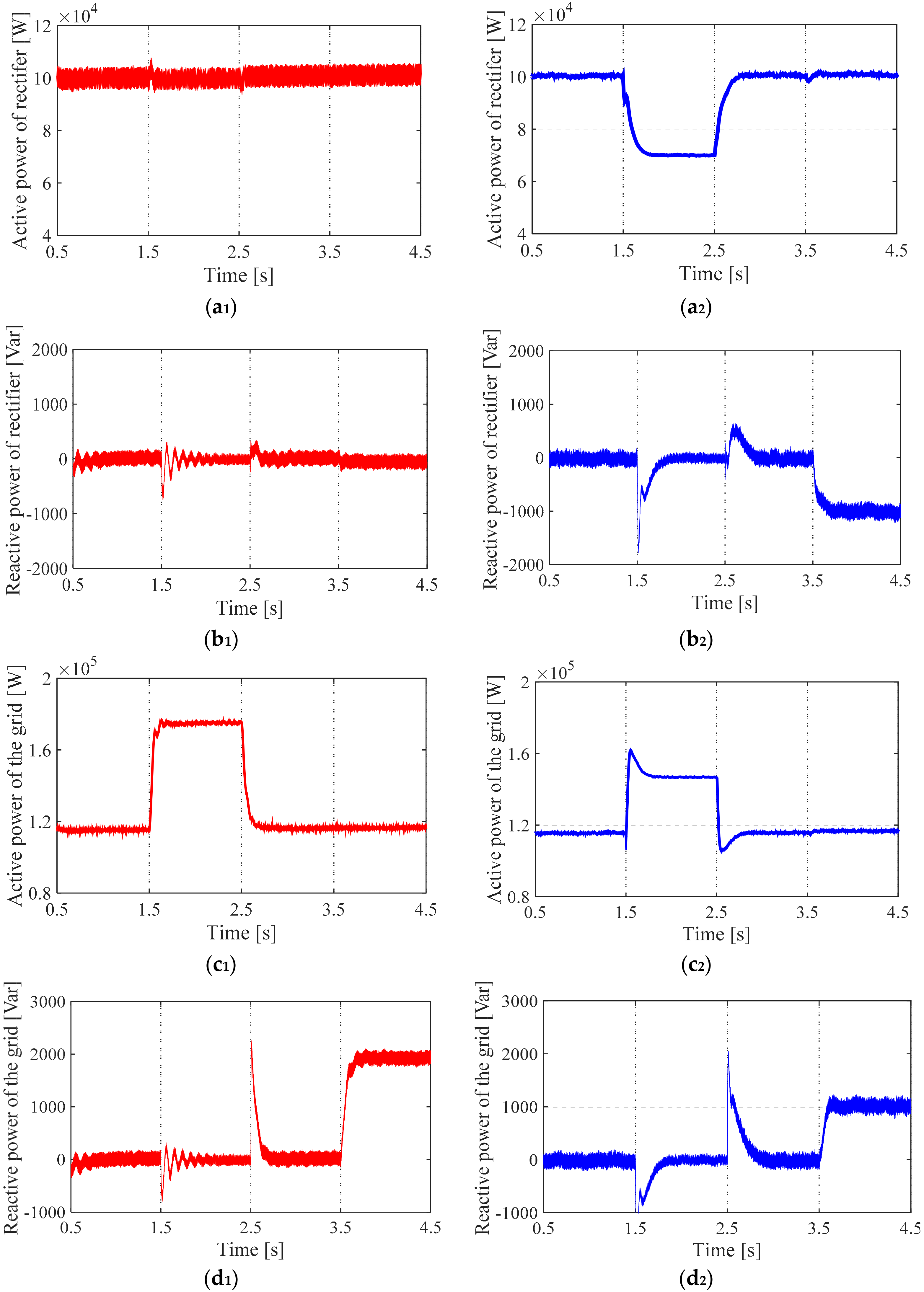
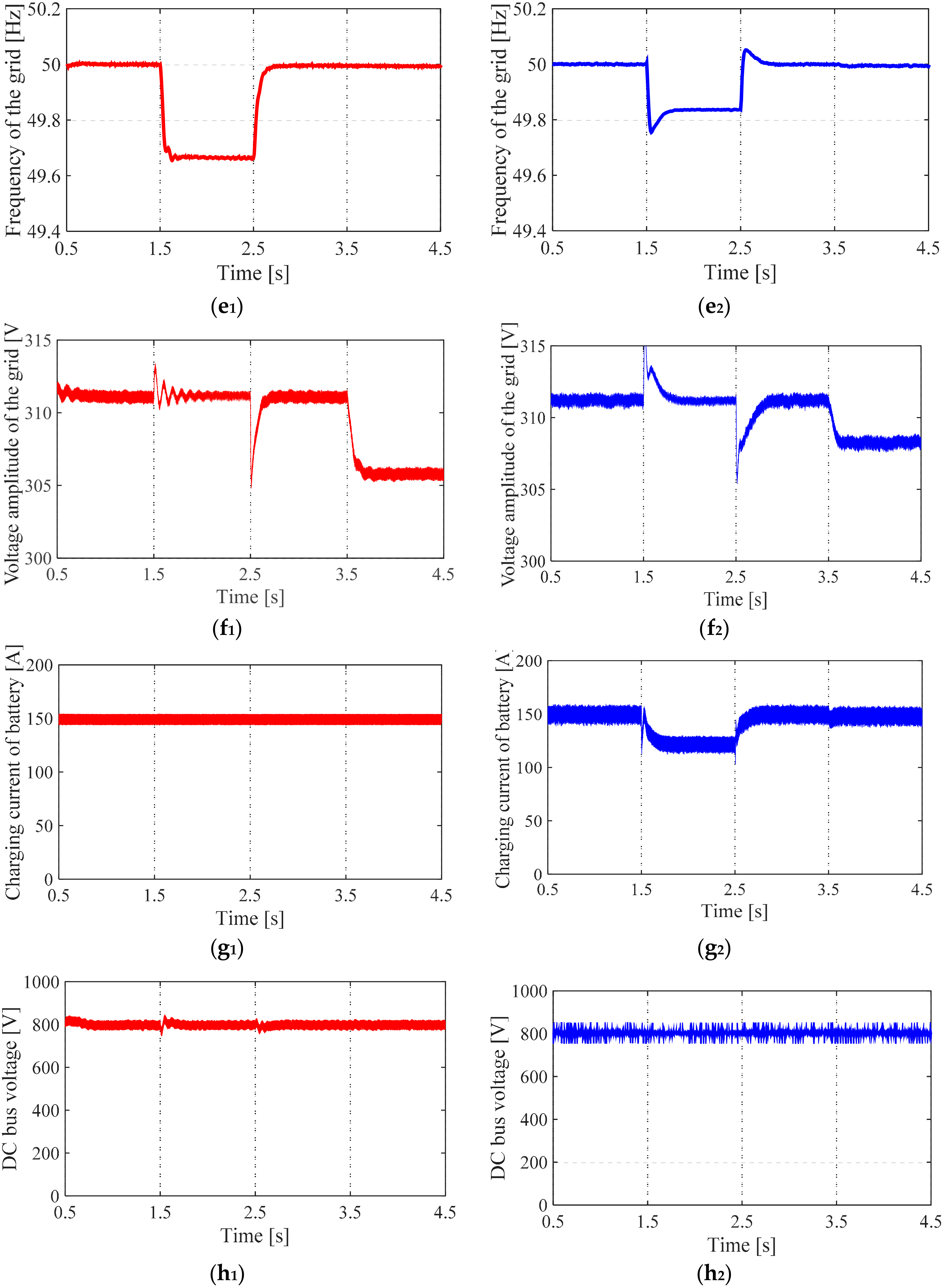
5.2.2. Comparison of Control Schemes

The superiority of the proposed VSM-based charging system is confirmed by comparing with the traditional control. Most noteworthy, the traditional control [19,20] means that the charging system does not possess the power regulation capabilities consistent with SM and only implements the charging function. The parameters of the VSM and grid are set in Table 2.
The proposed control and traditional control are applied to the off-board charger I, respectively. The variations of the two control methods on the frequency and voltage of the grid are contrasted when the power battery II joins in and drop out of services through off-board charger II and the reactive power of the AC interface fluctuates. To explain, for VSM-controlled off-board charger I, the rated capacity of the power battery I is 100 Ah, in order to make it work in a fast-charging mode, the charging current reference is set to 1.5 times rated capacity, i.e., Ibat* = 1.5 |Capacity| =150 A, so Pbat* = Ibat* × Ubat = 150 Ubat.
Based on the above situations and parameter settings, there are three simulation scenarios are considered:
The simulation time is 4.5 s. The grid quickly charged the power battery I with a charging current of 150 A through an off-board charger I before 1.5 s.
Power battery II is connected to the grid through the off-board charger II at 1.5 s, but the battery II exits operation at 2.5 s. In this time range, the consumed active power of the off-board charger II is 60 kW.
2 kVar reactive load at the AC interface is connected to the grid at 3.5 s.
The simulation results are given in Figure 10, where the red line indicates the traditional control (Denoted by x1, x = a, b, c, …, h) and the blue line represents the proposed control (Denoted by x2, x = a, b, c, …, h).
In the initial state, the grid rapidly charges the power battery I with 150 A charging current by the off-board charger I. When the power battery II is connected to the grid at 1.5 s and the reactive load is increased at 3.5 s, for traditional control, Figure 10a1,b1 show that the off-board charger I system does not partake in the active and reactive power regulation no matter how the loads change. In this case, the whole variations of power are entirely borne by the grid. As a result, the active power sent by the grid increases from 115 kW to 175 kW (as shown in Figure 10c1), which results in the decrease of 0.32 Hz in grid frequency (as indicated from Figure 10e1). Furthermore, From Figure 10d1,f1, after 3.5 s, the reactive power emitted by grid increases from 0 Var to 2000 Var, which causes the voltage amplitude to drop from 311.159 V to 306 V.
In contrast, for proposed control, the off-board charger I and the grid share the active and reactive power in a 1:1 ratio. Between 1.5 and 2.5 s, it can be observed from Figure 10a2,c2 that the active power of the rectifier reduces from 100 kW to 75 kW, and the power transmitted from the grid increases from 115 kW to 145 kW. The sum of these two adjustments equals the consumed active power 60 kW of the off-board charger II. Compared with traditional control, the grid frequency only declines to 0.17 Hz in Figure 10e2. In addition, aiming at the access of 2 kVar reactive load at 3.5 s, Figure 10b2,d2 display that the rectifier reduces the reactive absorption of 1 kVar and the grid generates 1 kVar of reactive power. According to reactive droop coefficient, the voltage amplitude of the grid is a 3.15 V declines in Figure 10f2, whose drop degree is less than traditional control. Since VSM-controlled off-board charger I is involved in the regulation of the frequency and voltage, the charging current of the power battery I is lowered in Figure 10g2 during the access period of the power battery II. However, the charging current remains constant at 150 A in the traditional control of Figure 10g1. Besides, it can be observed in Figure 10h2 that the post-stage closed-loop control can stabilize the DC bus voltage at a reference value of 800 V.

6. Conclusions

This paper has presented a novel VSM-controlled scheme applied to the fast charging of the off-board charger. Control strategies of the off-board charger control and synchronous grid model are designed respectively, and the above strategies are verified by simulation. The investigated VSM not only provides ancillary services like participation in primary frequency control, reactive power regulation, and inertia and damping support for the grid, but also can be capable of achieving fast charging of the electric vehicles. Meanwhile, double closed-loop control improves the voltage stability of the DC interface. The designed synchronous grid model can simulate the actual distribution network characteristics accurately. The proposed novel-VSM control strategy can effectively enhance the quality of the frequency and voltage in the distribution network, especially in the nearby of the electric vehicles fast charging stations.

Author Contributions

X.Y. proposed the research direction and the VSM control method. J.L. completed the VSM control method. X.Y. proposed the synchronous grid model. J.L. established the mathematical model of the synchronous model. X.Y., J.L., B.Z., Z.J., Y.T., H.Z. and Z.L. performed the verification and analyzed the results. J.L. wrote the paper.

Acknowledgments

This paper was supported by the National Electric Net Ltd. (SGTYHT/16-JS-19); National Natural Science Fundings of Hebei (E2018502134); State Grid Corporation of Science and Technology Project (PD71-17-008); Liaoning Power Grid Corporation’s 2018 Science and Technology Project “Research on the Reactive Power and Voltage Optimization Strategy and Evaluation Index Considering Source and Load Fluctuation Characteristics”.

Conflicts of Interest

The authors declare no conflict of interest.

References

  1. Van Roy, J.; Leemput, N.; Geth, F.; Buscher, J.; Salenbien, R.; Driesen, J. Electric vehicle charging in an office building microgrid with distributed energy resources. IEEE Trans. Sustain. Energy. 2014, 5, 1389–1396. [Google Scholar] [CrossRef]
  2. Soares, F.J.; Rua, D.; Gouveia, C.; Tavares, B.D.; Coelho, A.M.; Lopes, J.A.P. Electric vehicles charging: Management and control strategies. IEEE Ves. Technol. Mag. 2018, 13, 130–139. [Google Scholar] [CrossRef]
  3. Seljeseth, H.; Taxt, H.; Solvang, T. Measurements of network impact from electric vehicles during slow and fast charging. In Proceedings of the 22nd International Conference and Exhibition on Electricity Distribution (CIRED 2013), Stockholm, Sweden, 10–13 June 2013; pp. 1–4. [Google Scholar]
  4. Sun, B.; Dragičević, T.; Freijedo, F.D.; Vasquez, J.C.; Guerrero, J.M. A control algorithm for electric vehicle fast charging stations equipped with flywheel energy storage systems. IEEE Trans. Power Electron. 2016, 31, 6674–6685. [Google Scholar] [CrossRef]
  5. Shi, C.; Tang, Y.; Khaligh, A. A single-phase integrated onboard battery charger using propulsion system for plug-in electric vehicles. IEEE Trans. Veh. Technol. 2017, 66, 10899–10910. [Google Scholar] [CrossRef]
  6. Shi, R.; Semsar, S.; Lehn, W.P. Constant current fast charging of electric vehicles via a DC grid using a dual-inverter drive. IEEE Trans. Ind. Electron. 2017, 64, 6940–6949. [Google Scholar] [CrossRef]
  7. Badawy, M.O.; Sozer, Y. Power flow management of a grid tied PV-battery system for electric vehicles charging. IEEE Trans. Ind. Appl. 2017, 53, 1347–1357. [Google Scholar] [CrossRef]
  8. Nour, M.; Ramadan, H.; Ali, A.; Farkas, C. Impacts of plug-in electric vehicles charging on low voltage distribution network. In Proceedings of the 2018 International Conference on Innovative Trends in Computer Engineering (ITCE), Aswan, Egypt, 19–21 February 2018; pp. 357–362. [Google Scholar]
  9. Gray, M.K.; Morsi, W.G. Power quality assessment in distribution systems embedded with plug-in hybrid and battery electric vehicles. IEEE Trans. Power Syst. 2015, 30, 663–671. [Google Scholar] [CrossRef]
  10. Zhou, N.; Wang, J.; Wang, Q.; Wei, N. Measurement-based harmonic modeling of an electric vehicle charging station using a three-phase uncontrolled rectifier. IEEE Trans. Smart Grid. 2015, 6, 1332–1340. [Google Scholar] [CrossRef]
  11. Suul, J.A.; D’Arco, S.; Guidi, G. A single-phase virtual synchronous machine for providing vehicle-to-grid services from electric vehicle battery chargers. In Proceedings of the International Electric Vehicle Technology Conference & Automotive Power Electronics—EV-TeC & APE, Yokohama, Japan, 22–24 May 2014; p. 7. [Google Scholar]
  12. Suul, J.A.; D’Arco, S.; Guidi, G. Virtual synchronous machine-based control of a single-phase bi-directional battery charger for providing vehicle-to-grid services. IEEE Trans. Ind. Appl. 2016, 52, 3234–3244. [Google Scholar] [CrossRef]
  13. Liu, Q.H.; Lu, S.J. Charging and discharging control strategy based on virtual synchronous machine for electrical vehicles participating in frequency modulation of Microgrid. Autom. Elect Power Syst 2018, accepted. [Google Scholar]
  14. Jiang, W.; Lv, Z.; Zhong, Q.; Zeng, B.; Li, G. Virtual synchronous motor based control scheme of electric vehicle charger. In Proceedings of the 2014 International Conference on Power System Technology, Chengdu, China, 20–22 October 2014; pp. 2686–2692. [Google Scholar]
  15. Guerrero, J.M.; Vasquez, J.C.; Matas, J.; de Vicuna, L.G.; Castilla, M. Hierarchical control of droop-controlled AC and DC microgrids—A general approach toward standardization. IEEE Trans. Ind. Electron. 2011, 58, 158–172. [Google Scholar] [CrossRef]
  16. Rocabert, J.; Luna, A.; Blaabjerg, F.; Rodríguez, P. Control of power converters in AC microgrids. IEEE Trans. Power Electro. 2012, 27, 4734–4749. [Google Scholar] [CrossRef]
  17. Shen, Y.; Zhao, W.; Chen, Z.; Cai, C. Full-bridge LLC resonant converter with series-parallel connected transformers for electric vehicle on-board charger. IEEE Access 2018, 6, 13490–13500. [Google Scholar] [CrossRef]
  18. Vu, H.N.; Choi, W. A novel dual full-bridge LLC resonant converter for CC and CV charges of batteries for electric vehicles. IEEE Trans. Ind. Electron. 2018, 65, 2212–2225. [Google Scholar] [CrossRef]
  19. Varghese, A.S.; Thomas, P.; Varghese, S. An efficient voltage control strategy for fast charging of plug-in electric vehicle. In Proceedings of the 2017 Innovations in Power and Advanced Computing Technologies (i-PACT), Vellore, India, 21–22 April 2017; pp. 1–4. [Google Scholar]
  20. Zheng, Z.; Wang, K.; Xu, L.; Li, Y. A hybrid cascaded multilevel converter for battery energy management applied in electric vehicles. IEEE Trans. Power Electron. 2014, 29, 3537–3546. [Google Scholar] [CrossRef]
Figure 1. The main circuit topology and fast charger control strategy.
Applsci 08 00856 g001
Figure 2. Applied control structure of virtual synchronous motor (VSM).
Applsci 08 00856 g002
Figure 3. Comparison chart of the droop curves (a) Traditional droop curves; (b) Droop curves based on charging mode.
Applsci 08 00856 g003
Figure 4. Double closed-loop control.
Applsci 08 00856 g004
Figure 5. The synchronous grid model.
Applsci 08 00856 g005
Figure 6. Control strategy of the synchronous grid.
Applsci 08 00856 g006
Figure 7. Simulation model structure diagram.
Applsci 08 00856 g007
Figure 8. The influence of different inertia and damping on the active power of the rectifier (a) Different inertia J; (b) Different damping D.
Applsci 08 00856 g008
Figure 9. Primary regulation of VSM (a) Active power of the rectifier; (b) Frequency of VSM; (c) Reactive power of the rectifier; (d) Voltage amplitude of VSM.
Applsci 08 00856 g009
Figure 10. Dynamic response waveforms of the grid and off-board charger I (a1,a2) Active power of the rectifier; (b1,b2) Reactive power of the rectifier; (c1,c2) Active power of the grid; (d1,d2) Reactive power of the grid; (e1,e2) Frequency of the grid; (f1,f2) Voltage amplitude of the grid; (g1,g2) Charging current of the power battery I; (h1,h2) DC bus voltage.
Applsci 08 00856 g010aApplsci 08 00856 g010b
Table 1. Simulation parameters.
ParametersValues
Filter parametersThe series inductance of the filter, L3 mH
The series resistance of the filter, R0.5 Ω
The parallel capacitance of the filter, C10 μF
LLC converter parametersDC side capacitance, C1900 μF
Resonant inductor, Lr0.06 nF
Resonant capacitor, Cr34 μF
Excitation inductance, Lm0.24 nH
Transformer ratio, T1.4
Power battery parametersNominal voltage400 V
Rated capacity100 Ah
System parametersReference value of DC voltage, Udc-ref800 V
Resonant frequency35 kHz
Rated frequency50 Hz
AC phase voltage effective value220 V
Rectifier switching frequency10 kHz
Table 2. Control parameters of the VSM and grid.
ParametersValues
VSM control parametersThe charging power reference of the power battery I, Pbat*150 Ubat
The reactive power reference of the rectifier, Q*0 Var
The active droop coefficient of the VSM, Dp0.00009
The reactive droop coefficient of the VSM, Dq0.003
The virtual Inertia of the VSM, J0.1
The virtual damping of the VSM, D20
Grid control parametersThe active power reference of the grid, Pe*200 × 103 W
The reactive power reference of the grid, Qe*0 Var
The active droop coefficient of the grid, Dpg0.00002
The reactive droop coefficient of the grid, Dqg0.003
The virtual Inertia of the grid, Jg0.01

