1. Introduction
Two important factors in the process of using a car are its reliability and running costs. They depend not only on the vehicle structure but also on the assumed operational rules. The handling system serves the purpose mainly of restoring (regenerating) the running potential of the vehicle, which decreases as a result of natural wear or damage caused by wrong operation or errors and faults occurring in the process of construction or production.
The introduction of ever better methods of diagnostic tests makes it easier to use the method of restoring the running potential, which consists in repairing or replacing particular systems before they reach their boundary state, and most of all before a failure occurs, making a vehicle unfit for use [
1,
2,
3,
4]. Functional diagnostics conducted on a regular basis ensures reliable work of the starter, its optimal usage, and in particular the prevention of unexpected failures in the course of vehicle operation [
5,
6,
7,
8]. In order to achieve the basic goals of functional diagnostics, it is important to choose such starter parameters, which can optimally allow one to draw conclusions about its technical condition. Diagnostics can predict in advance when the starter’s basic elements approach their boundary or critical condition [
9,
10,
11,
12].
The aim of this study is to work out a new method of controlling the operating wear of the car starter. The method consists in making use of a magnetic field in the armature slot as a diagnostic signal for determining fitness for use. To achieve the goal of discovering a method of starter functional diagnostics, a test stand was designed and constructed, and the test objects (i.e., starters) were properly prepared.
2. Analysis of the Magnetic Circuit and Distribution
The magnetic circuit of the starter can be divided into two basic parts:
The two parts are separated by an air gap called the armature gap. In the stator part of the magnetic circuit, the following elements can be distinguished: a pole shoe, a main pole core (pole body), an air gap between a core and a yoke (when a core and a yoke are made of separate parts), and a yoke [
13].
In the rotor part, the elements of the magnetic circuit are the following: armature teeth and the armature core. The size of the armature gap has a significant impact on the characteristics and dimensions of the machine. On the one hand, it is advisable to make the size of the
δ gap smaller because it causes the decrease in the magnetic tension of the gap. At the same time, the dimensions of the machine may become smaller because less space is necessary to accommodate excitation winding. This makes it possible to decrease the height of the pole and consequently to make the outer diameter of the machine smaller at a constant armature diameter. Excitation losses are becoming smaller as well. However, at small values of
δ, the magnetic field of the machine changes when there are load variations, which has a negative impact on commutation and leads to its unstable work [
14]. The size of the armature gap is usually not constant along the armature perimeter because the arch of the pole shoe may be of different shapes depending on the required distribution of magnetic field in the gap. Most frequently, the gap is constant and concentric along the rotor (about 0.6÷0.7 of the pole piece width), and, near the pole horns, it increases to 2
δ.
If the gap was the same along the whole arch of the pole, a rapid change in magnetic induction on the pole horns would occur. It would cause more losses in teeth steel and in armature winding and the increase of noise generated by the machine [
15,
16,
17].
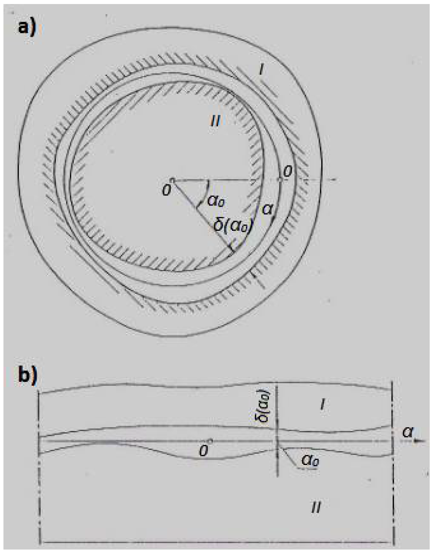
The properties of electric machines depend on the distribution of the radial constituent B
r of magnetic induction in the air gap between the stator and the rotor [
18]. The course of function
Br = f(
α), describing the distribution of induction depending on angle
α, is called the field distribution or the magnetic field curve (
Figure 1).
Field distribution depends on the following factors [
19]:
the current distribution along the inner circuit of the stator core and the outer circuit of the rotor core,
the distribution of magnetization vector of permanent magnets,
the shape of the air gap between the stator and the rotor, and
the magnetic tension in stator and rotor cores.
Even at drastic simplifications consisting in neglecting magnetic tension in the core and assuming smooth by-gap surfaces of the armature and the poles, it is difficult to formulate analytical dependency describing induction distribution in the gap depending on the dimensions of the magnetic circuit and the winding. Such difficulties are the result of the complex shape of magnetic circuit elements. In the analysis of induction distribution in the electric machine, there are many additional simplifications.
It is assumed that the magnetic field in the gap is flat, i.e., the winding wires are parallel to the rotor rotation axis; in the core there are no radial passages; the deformation of field distribution on the core edges is neglected [
20]. The gap length in radial direction is so small in comparison with the other core dimensions that, for the purpose of analyzing field distribution, the cylindrical layout can be replaced with the flat one after outspreading the core which has been cut open (
Figure 1b).
2.1. Magnetic Field from Excitation Winding
Induction in gap
Bδfx from excitation winding is proportional to field strength
Hδfx.
where air magnetic permeability
μs = 4π × 10
−7 H/m.
The strength of magnetic field
Hδfx can be expressed by the following formula when magnetic tension drops in the iron core are neglected:
When magnetic tension drops in the air gap,
where
Ff is the magnetic tension of magnets, and
Θf is the excitation flow of one pair of poles.
where
zf is the number of coils on all poles,
p is the number of pole pairs, and
If is the excitation current.
The gap length is calculated as follows:
The Carter coefficient
kc denotes a calculative increase of the air gap as a result of the existence of grooves, usually
kc = 1.05 ÷ 1.2. Eventually, the distribution of induction from excitation winding can be approximately determined from the following formula:
Function
δ(
x), present in the formula, is determined on the basis of the set shape of the pole shoe. The interpolar gap and the edges of the pole shoe are the places where equivalent gap length equal to the length of magnetic field lines between the armature and the pole can be determined. Field distribution is determined separately for each pole, assuming that there are no adjacent poles. Then, by summing field distributions of two consecutive poles, the resultant distribution can be obtained from the formula:
An example of induction distribution for a machine with a concentric gap is presented in
Figure 2, in which the pole pitch
where
D is the armature diameter, and
p is the number of pole pairs.
2.2. Magnetic Field from Armature Current
A machine with current
Ia flowing in bars laid in grooves can be treated as a machine with a layer of current placed on the machine circuit, i.e., with a loading of current A. The loading of current from the armature of the direct current machine can be determined by Equation (9):
where
Ig is the current in particular branches,
Ia is the current in the circuit of brushes,
a is the number of parallel branch pairs,
p is the number of pole pairs, and
τ is the pole pitch
When the brush axes are placed in axis
q, the flow direction
Θa is equal to the direction of axis
q. When the armature moves, the flow direction
Θa does not change. If magnetic tension drops in iron cores are neglected, magnetic tension in the gap (between the surface of the armature and the surface of the pole shoe) in point c is determined by the following formula:
and is shown as a straight line
Uμδax (
Figure 3).
Magnetic field strength is expressed as follows:
where
lx is the length of flow track in the air, (
lx =
kc∙
δ(
x))
Magnetic induction in the gap from armature current is expressed as follows:
Figure 3 presents curve
Bδax, which illustrates induction distribution
Bδax for brushes placed in axis
q.
2.3. Resultant Magnetic Field of the Starter
In the direct current engine, resultant induction in gap
Bδx is the sum of induction in the gap from excitation current
Bδfx and induction in the gap from the armature current (from armature reaction)
Bδax.
The resultant induction is smaller under half of the pole piece as a result of magnetic circuit saturation.
Figure 4 presents the distribution of the resultant induction.
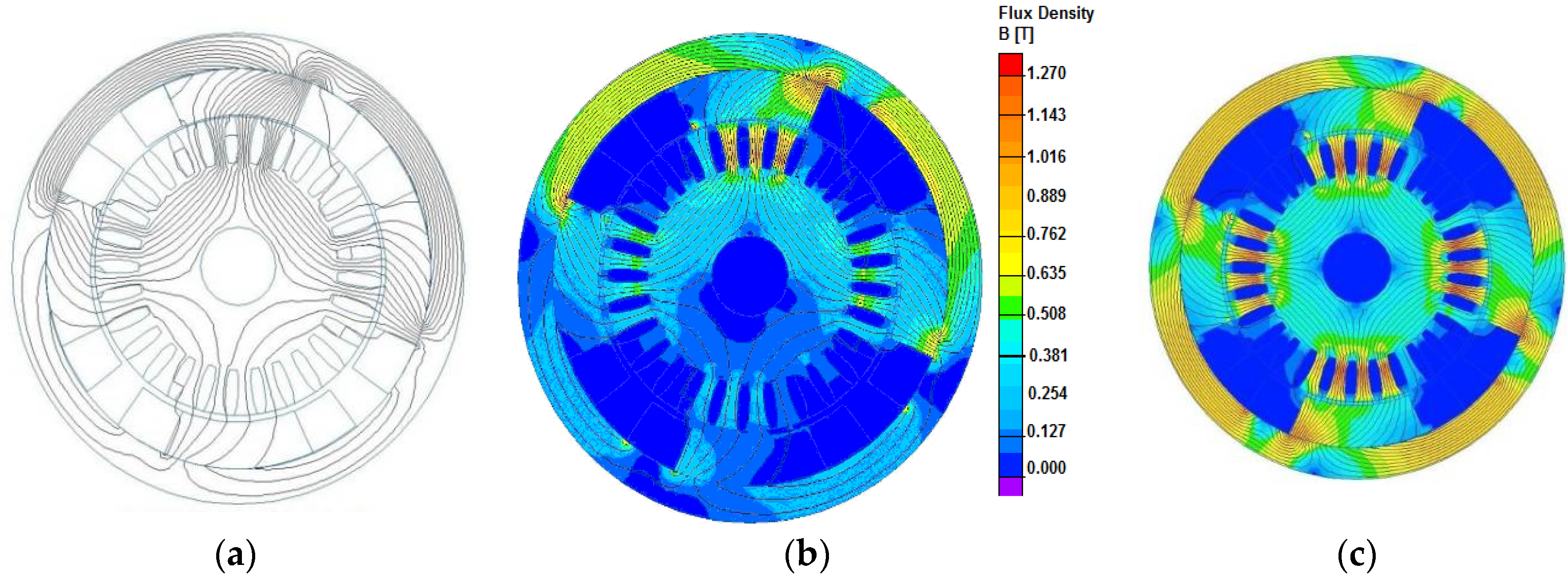
By simulating the operational wear of the starter sleeve that changes the armature gap, the distribution of the magnetic flux and the magnetic induction in the gap were determined.
Figure 5a shows the spread of the magnetic flux for the starter R5 for the gap in a segment of the commutator.
Figure 5b shows the distribution of the induction for an armature gap of 1 mm, as well as the damage in the form of the gap in two segments of the commutator and the worn sleeve of the starter R5.
Figure 5c shows the distribution of the induction for the efficient starter. The new diagnostic method allows one to clearly identify the degree of the operational wear of the sleeves as well as the damage in the form of interruptions and short-circuits of the rotor windings. The simulation was performed on the real object using the QuickField program. Apart from starter dimensions, data on the type of excitation, the number of starter grooves, and the material magnetization curves for the rotor and stator were introduced to the program. A variable value of the armature gap was introduced, resulting from the wear of the sleeve. The simulation results indicate that the highest values of magnetic induction occur in the four sections of the yoke between the pole shoes and the yoke gap. For an efficient starter (
Figure 5c), the maximum induction value is 0.8 T.
3. Experimental Studies of Induction Distribution in the Magnetic Gap
The starter R76a with two Hall sensors (DKWP 10-40) was used in tests. One of them was placed on the rotor, the other one on the stator. The tests were conducted for two load states, i.e., idle running and partial load. The simulation of failures was limited to chosen cases:
- (1)
rotor winding ground;
- (2)
the shorting of two commutator sectors;
- (3)
the breaking of the integrity of rotor winding;
- (4)
the shorting of an excitation winding coil;
- (5)
wear of brushes.
The simulation was limited because certain failures, such as the stator winding ground made it impossible for the starter to work, even when it was idling.
3.1. The Description of the Test Stand
3.1.1. The Object Tested
The starter R76 is a series direct current motor adjusted for working in a one-conductor wiring system with a voltage of 12V. It is equipped with an electromagnetic switch closing the main circuit and a coupling mechanism triggering the mesh of the starter coupling system with the engine flywheel for the time of the start-up. The coupling system placed on a screw spline is equipped with a four-roller unidirectional clutch, which protects the rotor of the starter from damage caused by external drive. The friction system made of fiber pads makes the rotor brake the very moment the power supply is cut off, which enables one to connect the rotor again very quickly. The starter is intended to start a spark ignition engine.
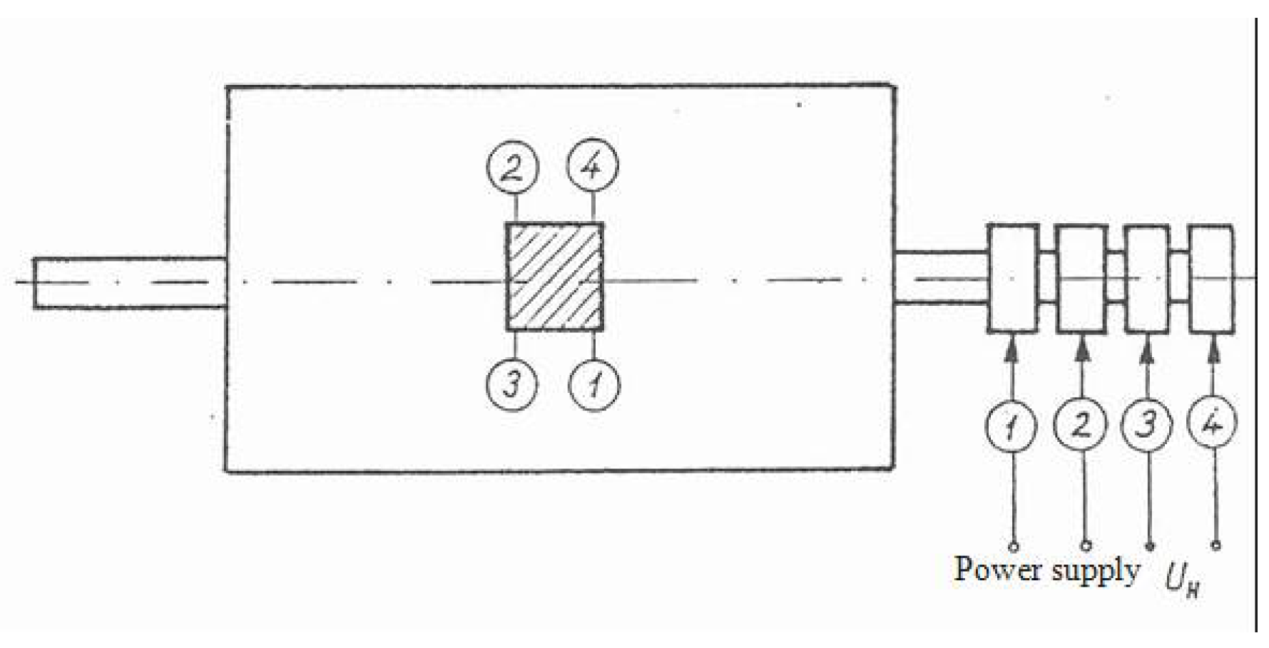
3.1.2. Connecting and Fixing Hall Sensors
The Hall sensor is fixed in pole shoe milling and the wires are introduced through openings in the pole piece and the frame.
Figure 6a shows how the wires are connected, and
Figure 6b shows the Hall sensor placed on the pole shoe in the starter.
Figure 7 shows the connection of the Hall sensors, and
Figure 8a presents the view of the starter. The Hall sensor on the rotor is shown in
Figure 8b.
The Hall sensor is stuck in the rotor tooth notch halfway through its length. Electric cables laid in the rotor grooves and in the rotor axis hollow are connected to four slip rings placed on the rotor axis, specially lengthened for this purpose.
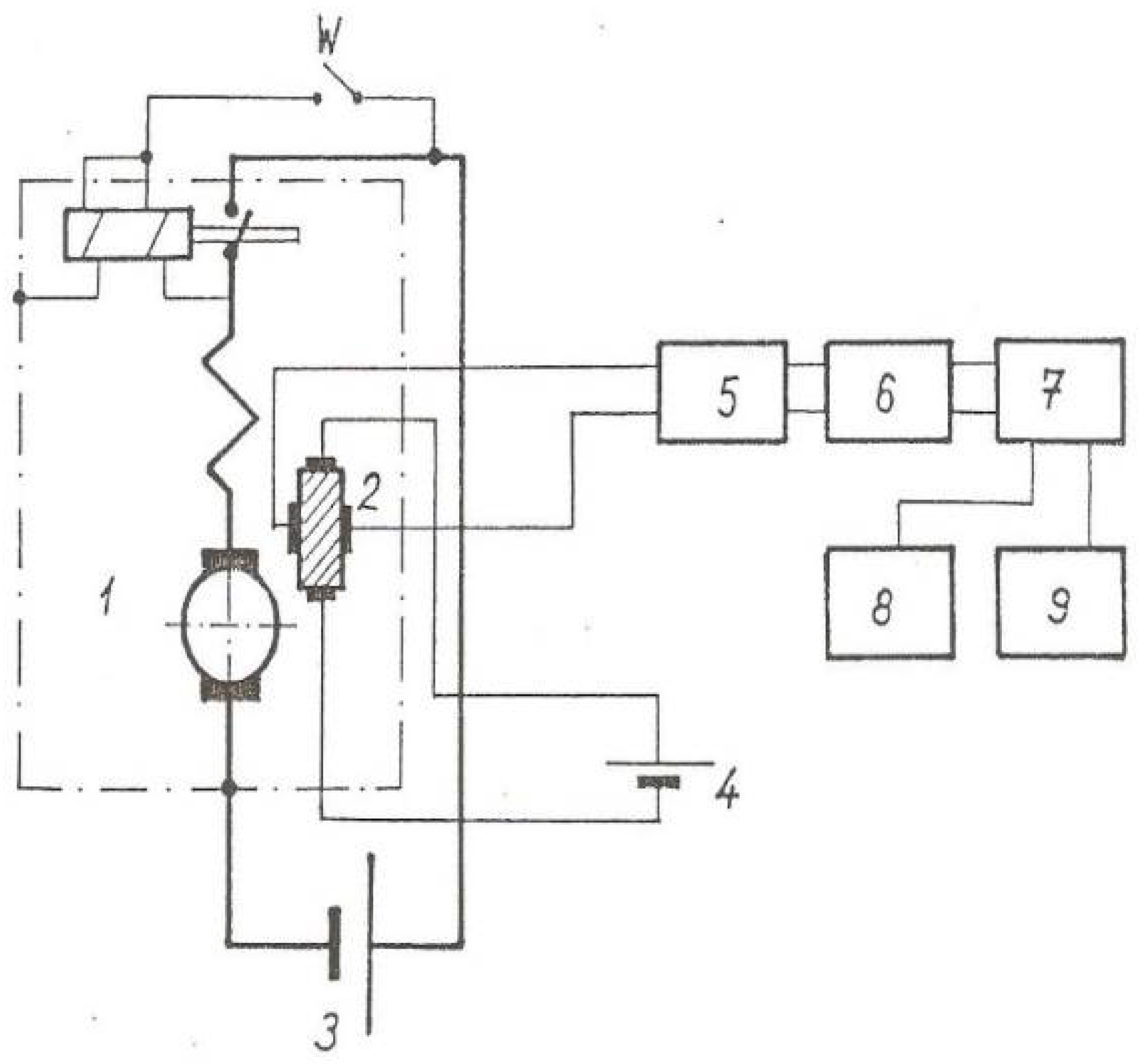
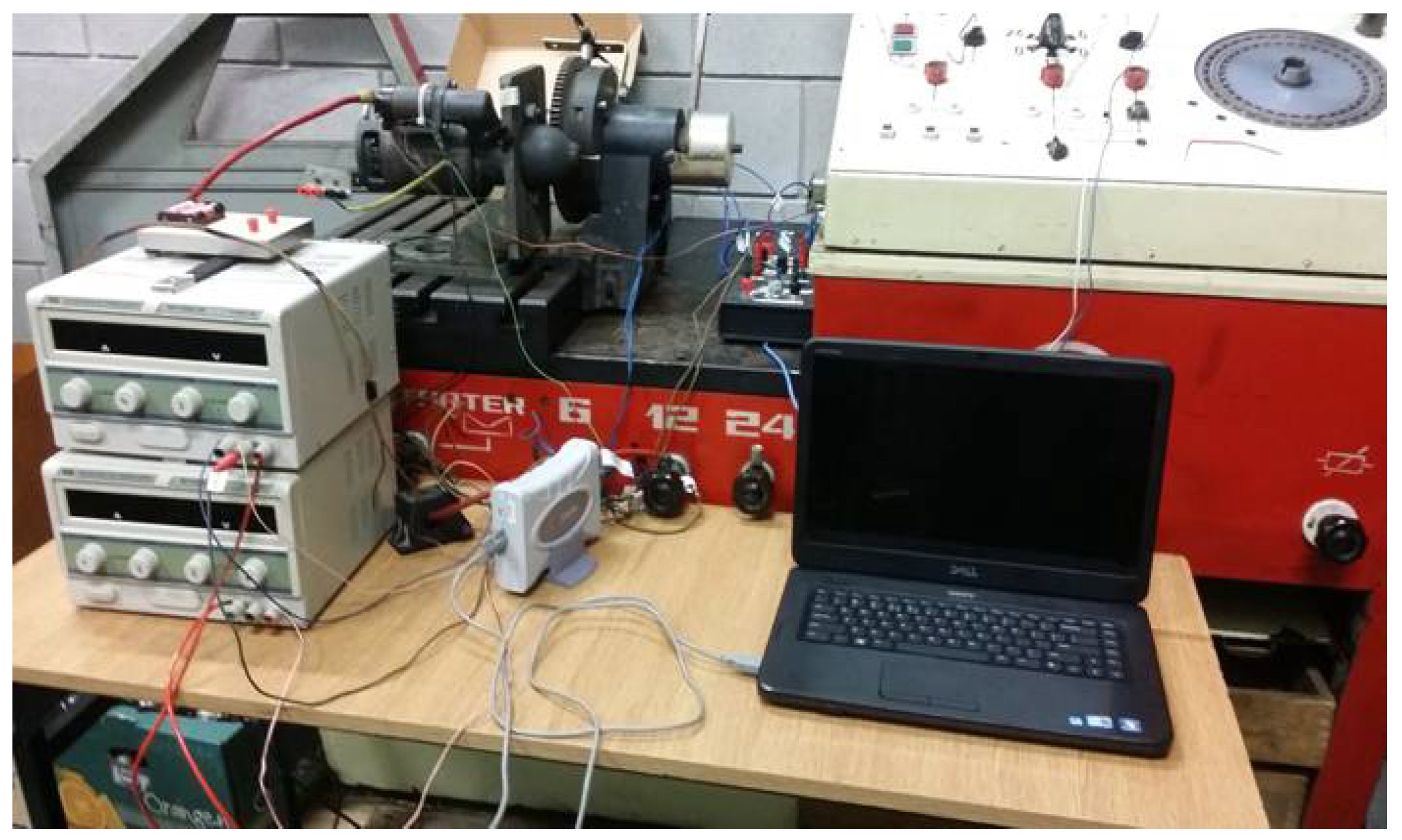
3.1.3. Measurement Stand
In the course of tests, the starter was mounted on an Elkon Super 3 type test stand. Such a stand was used only for loading the starter with a constant moment value. The starter was supplied by a separate 12 V battery. The signal from the Hall sensor was passed to the amplifier and from the amplifier through the protective system to the computer with an analogue-to-digital converter.
Figure 9 presents the diagram of the stand. The view of the stand is shown in
Figure 10.
3.2. The Course of Measurements
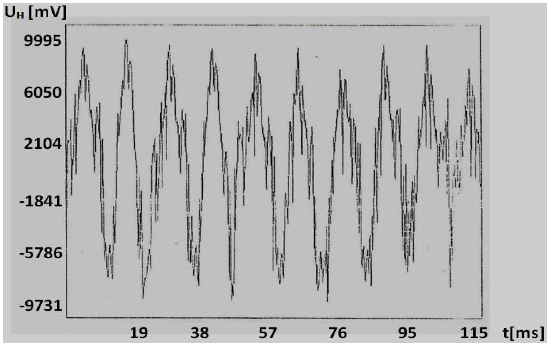
Testing the starter with the Hall sensors consisted in recording the voltage waveforms obtained from the Hall sensors, which was commensurate with magnetic induction (magnetic flux B is proportional to Hall voltage and inversely proportional to the supply current with a constant Hall sensor coefficient). The Hall voltage signal was amplified on the voltage amplifier.
As one Hall sensor was placed on the rotor and the other one on the stator, it can be assumed that both Hall sensors were in the air gap and thus recorded the course of induction in the gap. It turns out that such a course is different for different failures and differs from the course of an efficient starter. Induction distribution in the air gap can be a diagnostic parameter of the starter and can be used to assess its technical condition. The tests were carried out in such a way that the course of induction was recorded for the unloaded starter, i.e. at its idle running, and for the loaded one, but with the same load for all cases.
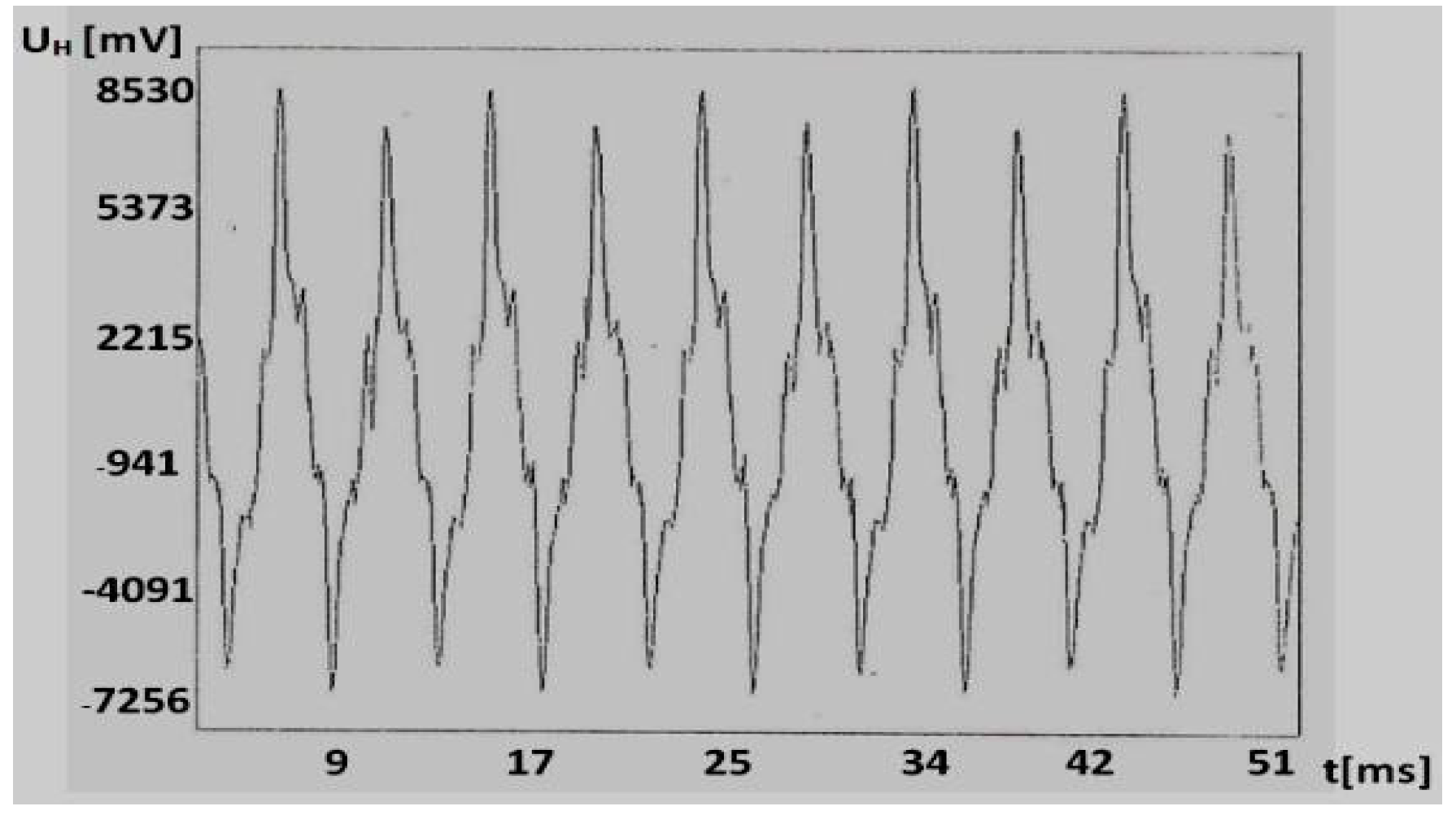
4. Test Results
The waveforms of induction distribution measured by Hall sensors fixed on the rotor and on the stator are very similar. However, the course of induction recorded by the Hall sensor fixed on the rotor provides more information useful in the analysis of starter failures in the form of a short circuit and a break in the rotor windings, which is related to the curve of the rotor and stator interaction field (Equation (7)).
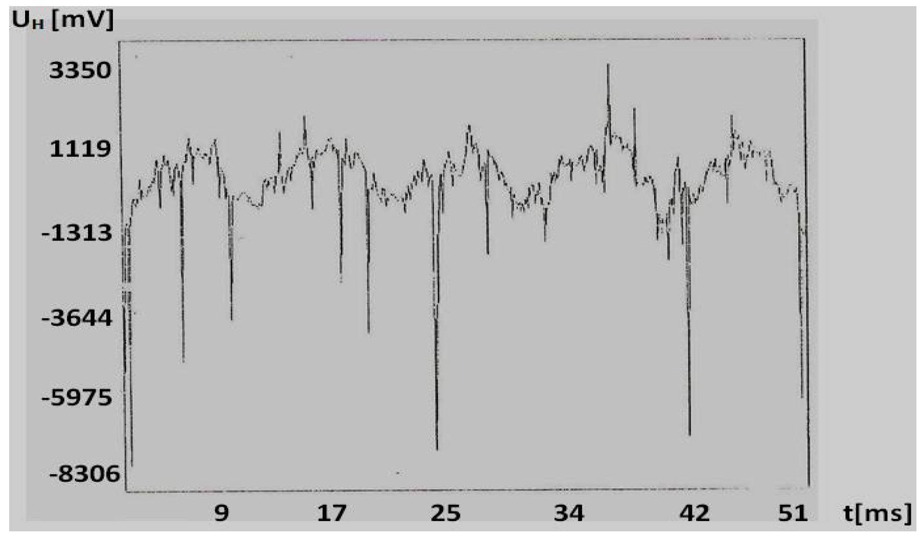
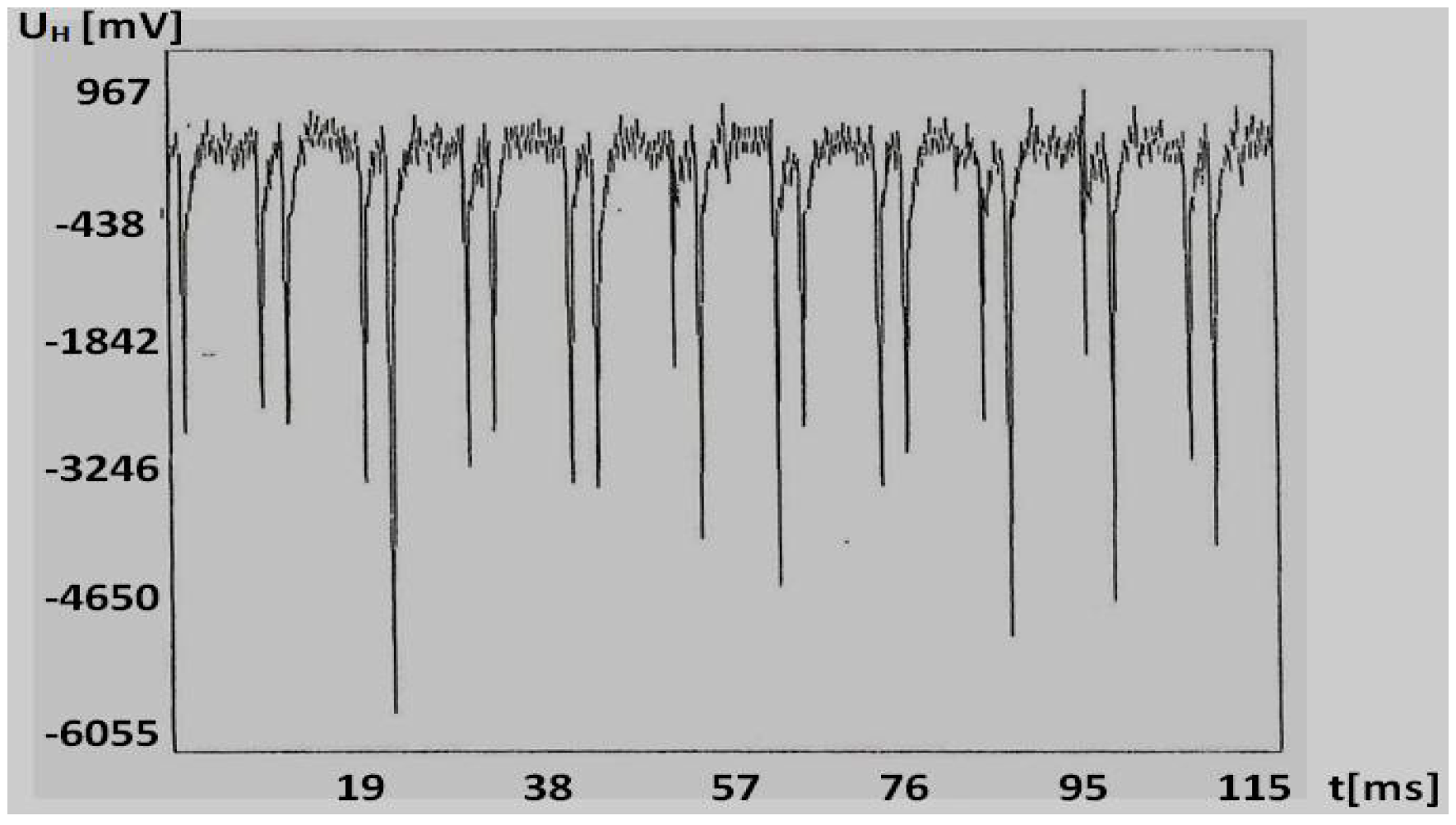
The waveforms of failures, in relation to the charts of the efficient starter, are more regular. e.g., for the shorting of two commutator sectors. Their course is characteristic in the case of breaks in the rotor winding. A completely different course is obtained here and its character does not resemble any of those discussed earlier. What makes it characteristic are the visible peaks going down, probably caused by power surges resulting from breaks in the current circuit of the starter at the moment when the last commutator sector (before the sector whose winding solder was removed) emerged from under the brush, breaking the starter induction circuit.
5. Conclusions
The tests of the starter carried out with the Hall sensor confirm the assumptions that it can be used for car starter diagnostics, and at the same time for assessing its technical condition. It can also be concluded from the tests that diagnosing starters by means of the Hall sensor placed on the pole shoe is more useful (because it is easy to draw the Hall sensor wires out).
Although the system with the Hall sensor placed on the rotor provides more information about magnetic field distribution in the armature gap, it is more complicated as it requires using additional slip-rings and brushes necessary for letting wires out of the Hall sensor placed on the movable rotor. Such an option can be used in laboratory tests. The recorded voltage waveforms allowed for the elaboration of a diagnostic model for an operational control system of the starter condition for motor transport. Characteristic changes in the course of registered magnetic induction were subjected to FFT analysis, and a database for individual failures was developed, which is the subject of other articles.


 ,
, 


