A Design Method for Multijoint Explosive-Proof Manipulators by Two Motors


Abstract
:1. Introduction
2. Materials and Methods
2.1. Power Switch Unit
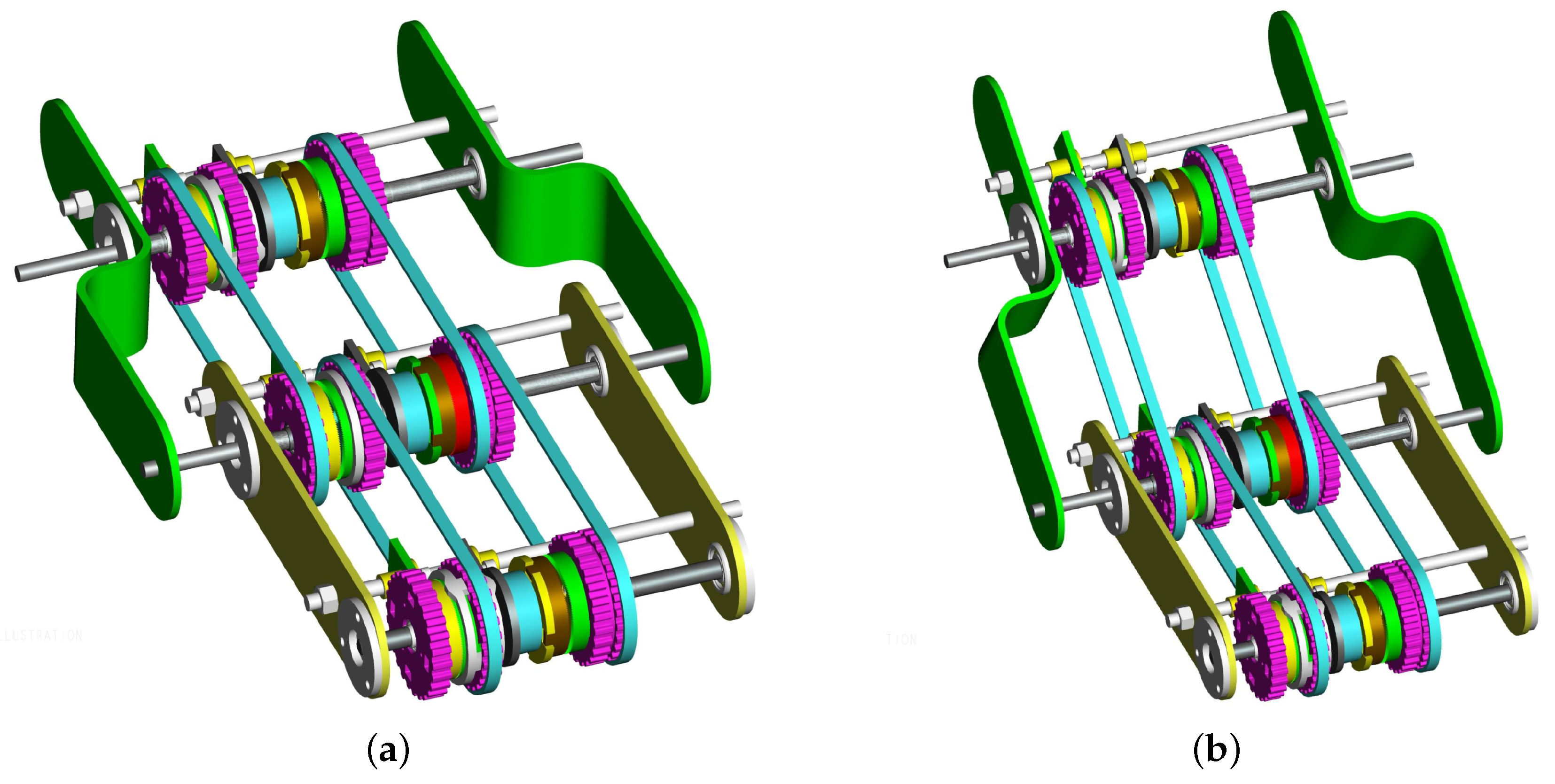
2.1.1. Transmitting Power to Joints
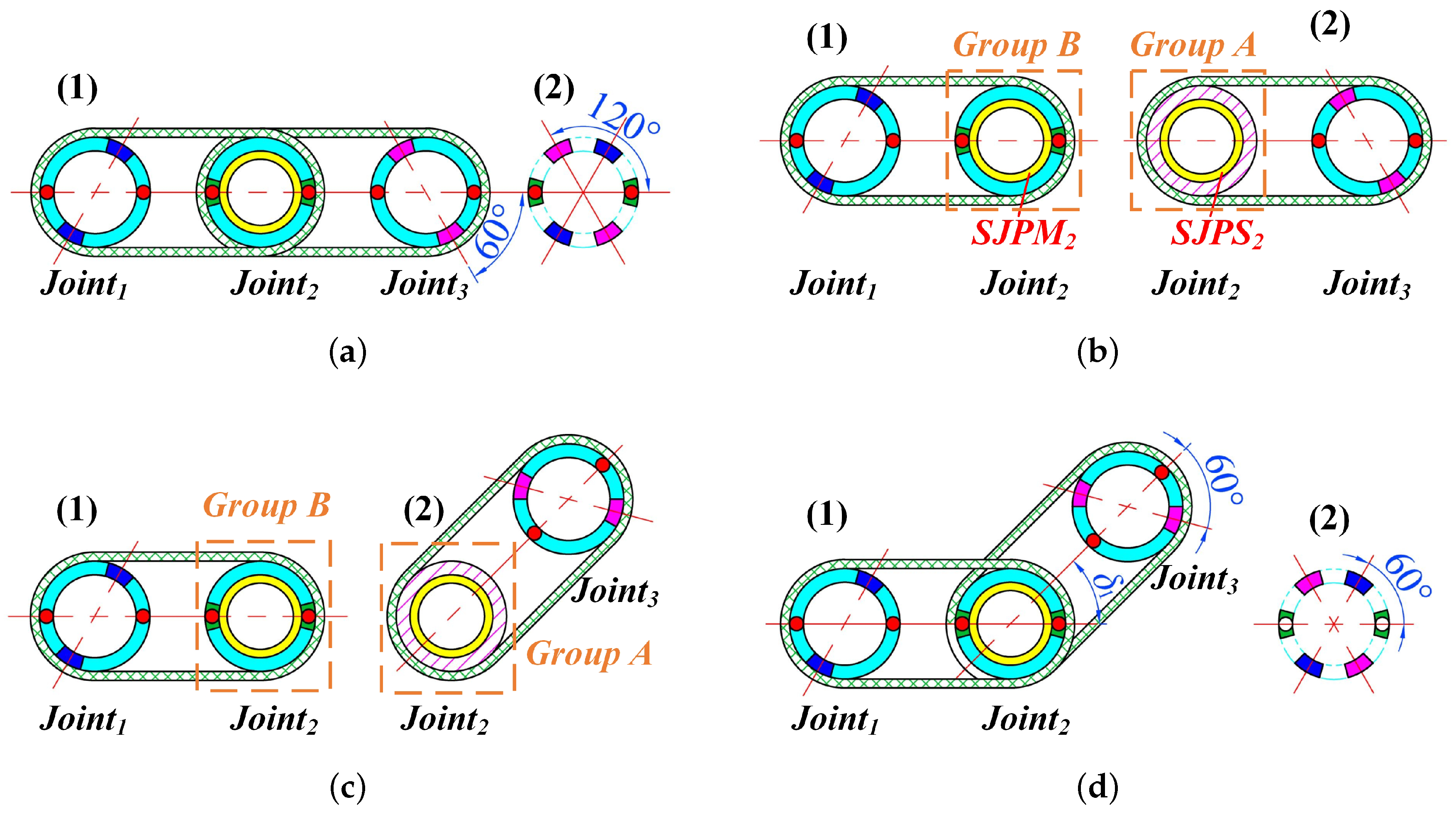
2.1.2. Motion of Switching Power among Manipulator Joints
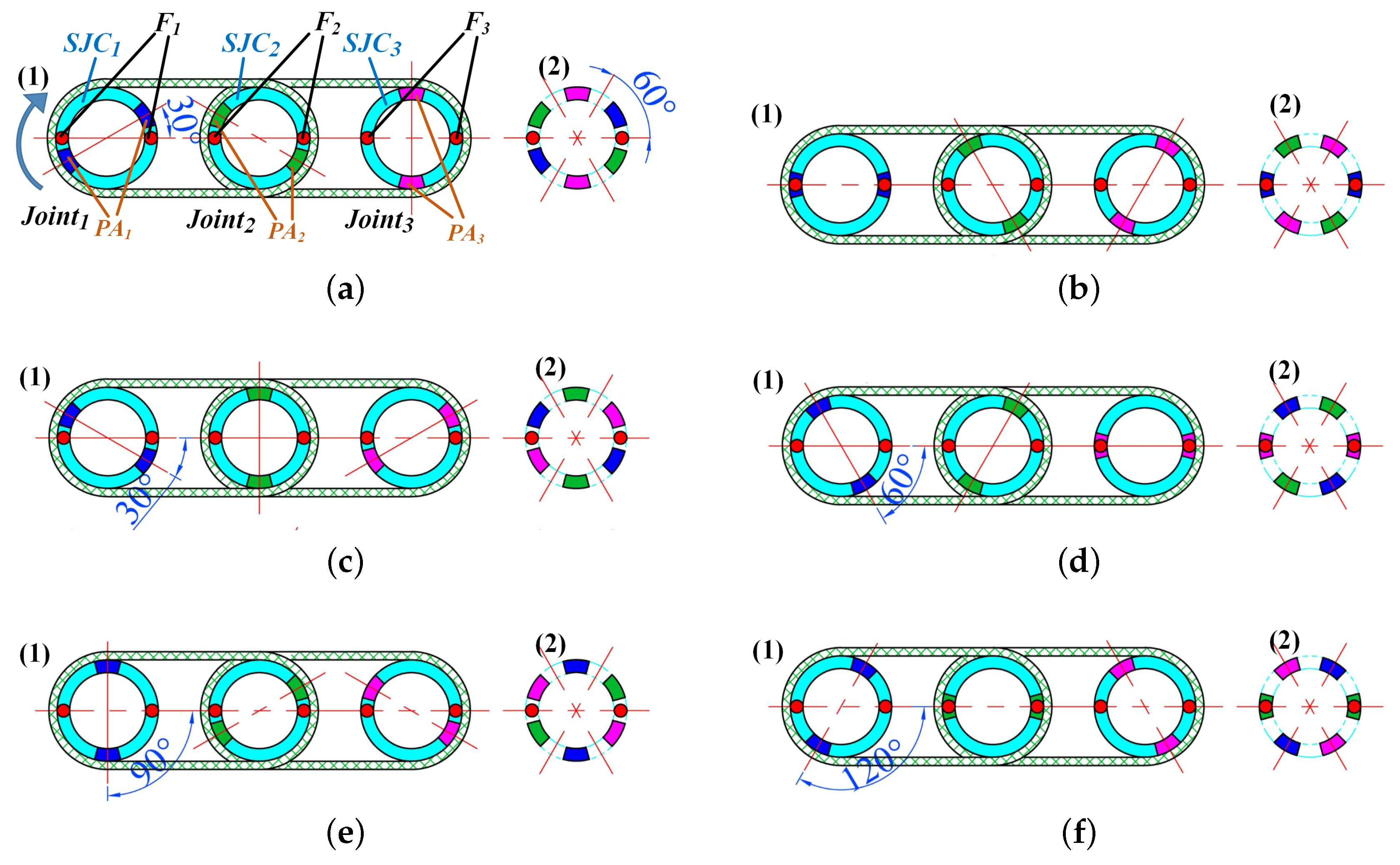
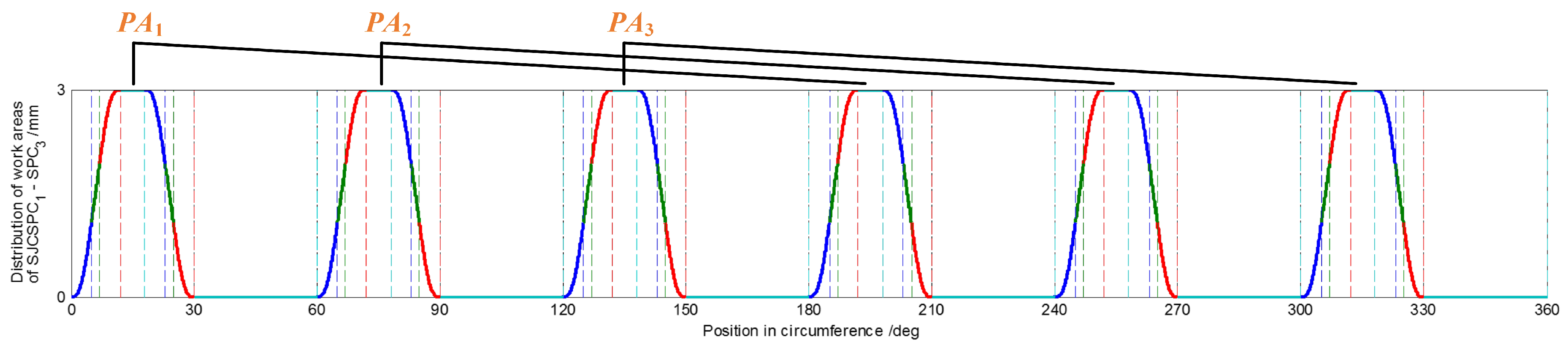
2.1.3. Cams Design Method
2.2. Motion Theory of the Manipulator
2.2.1. Phase Difference Caused by Joint Rotation
2.2.2. Power Switching among Joints
3. Results
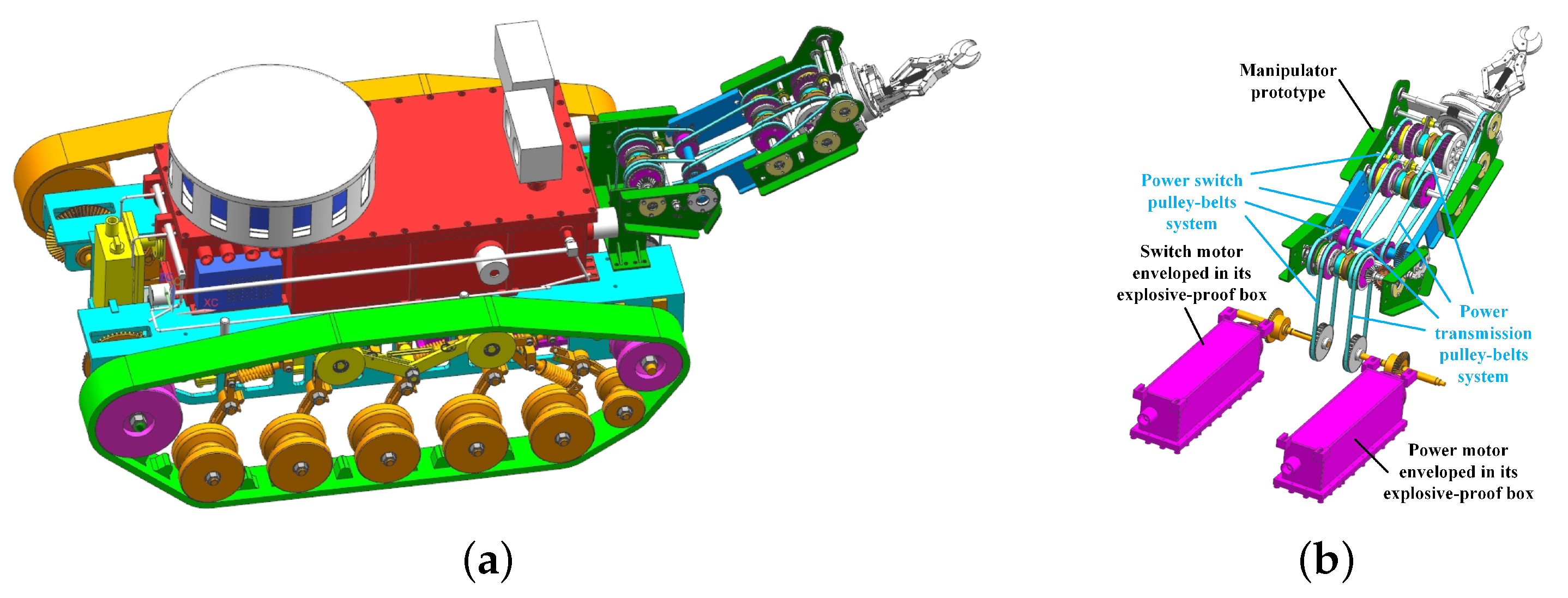
3.1. The Manipulator Prototype as an Example for Applying the Design Method
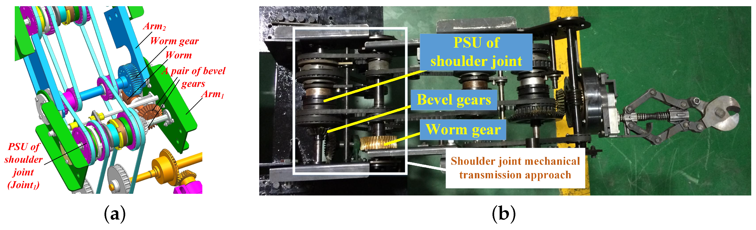
3.1.1. Shoulder Joint of the Manipulator Prototype
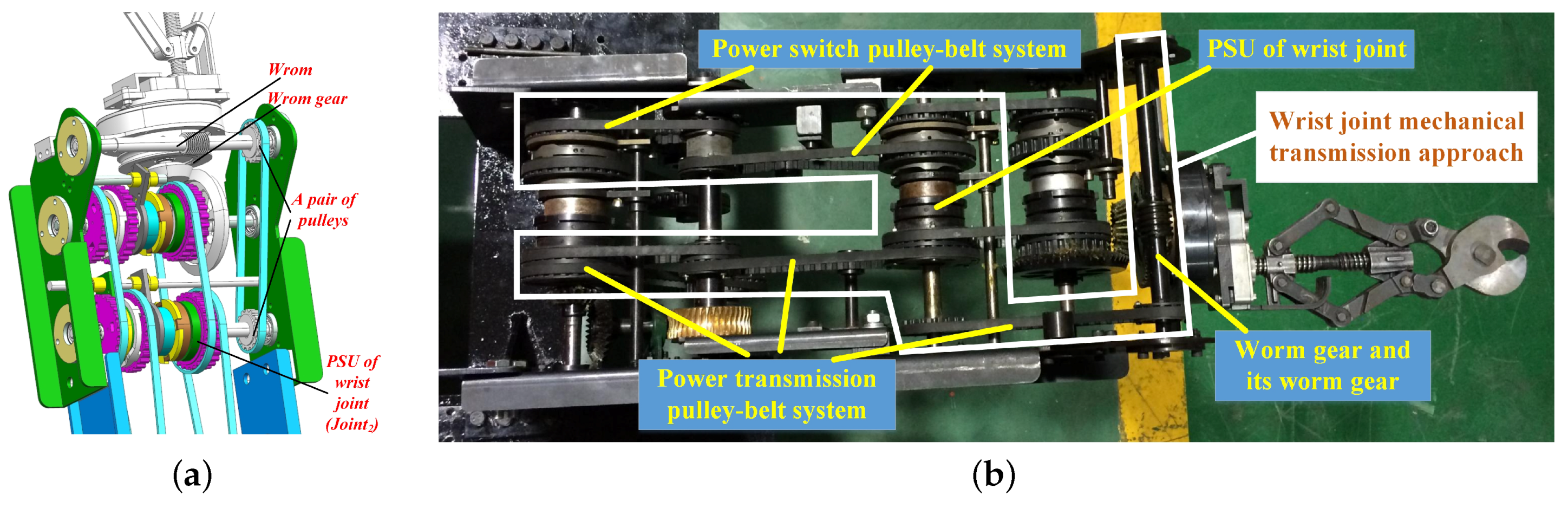
3.1.2. Wrist Joint of the Manipulator Prototype
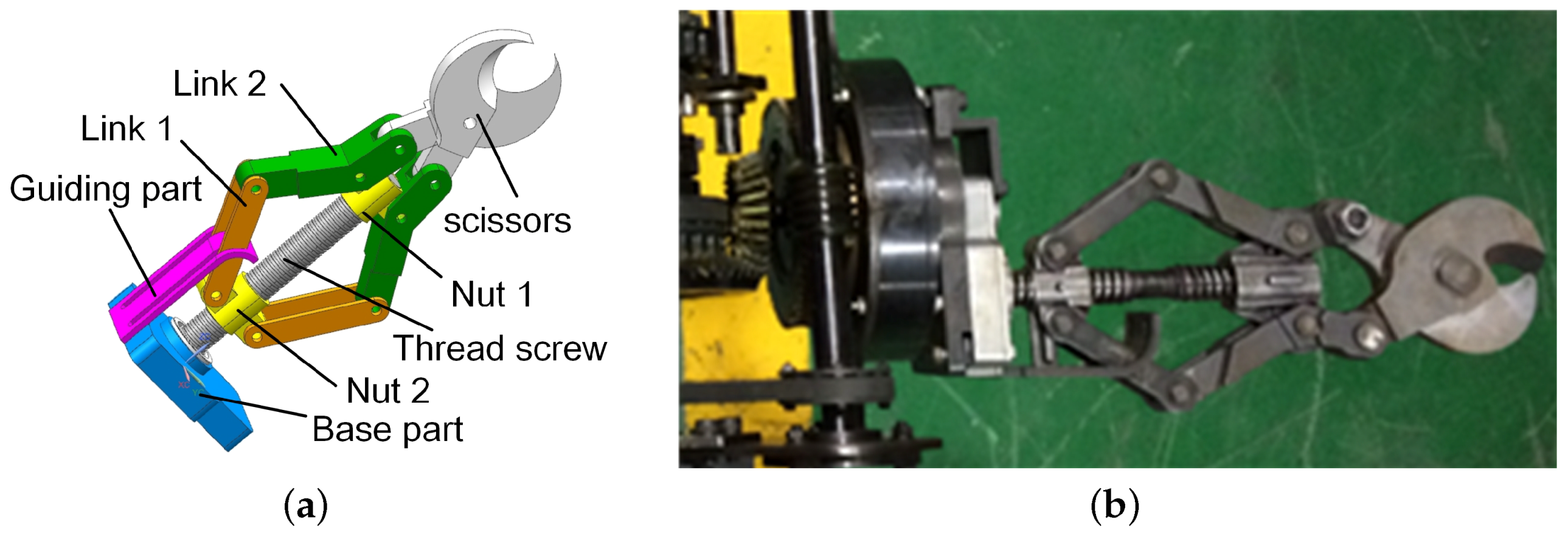
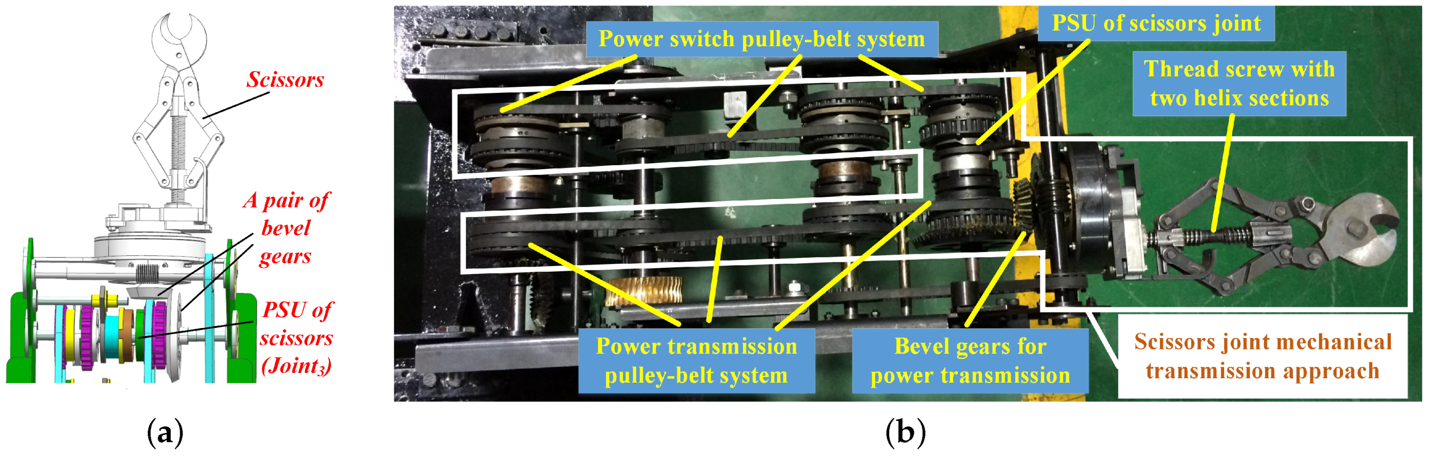
3.1.3. Scissors Joint of the Manipulator Prototype
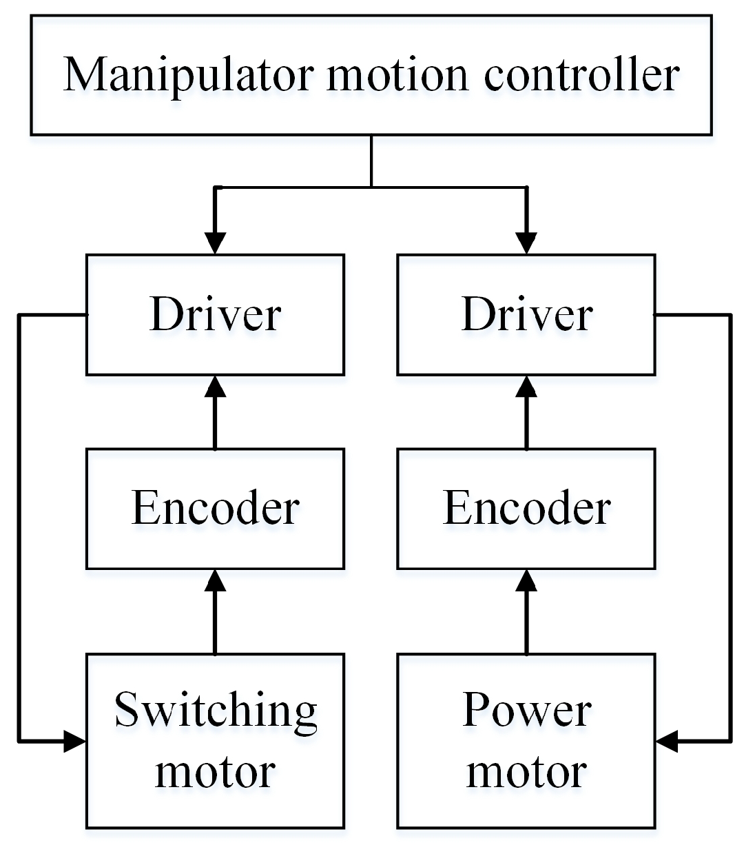
3.1.4. Design of the Control System of the Manipulator Prototype
3.2. Experiment
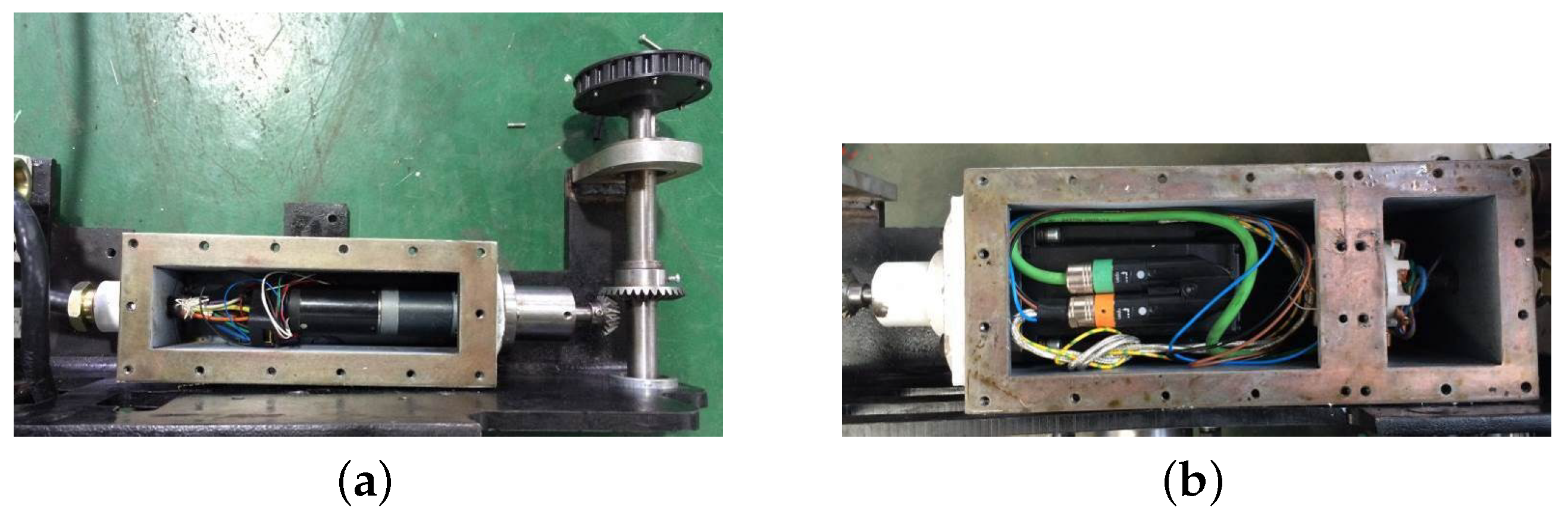
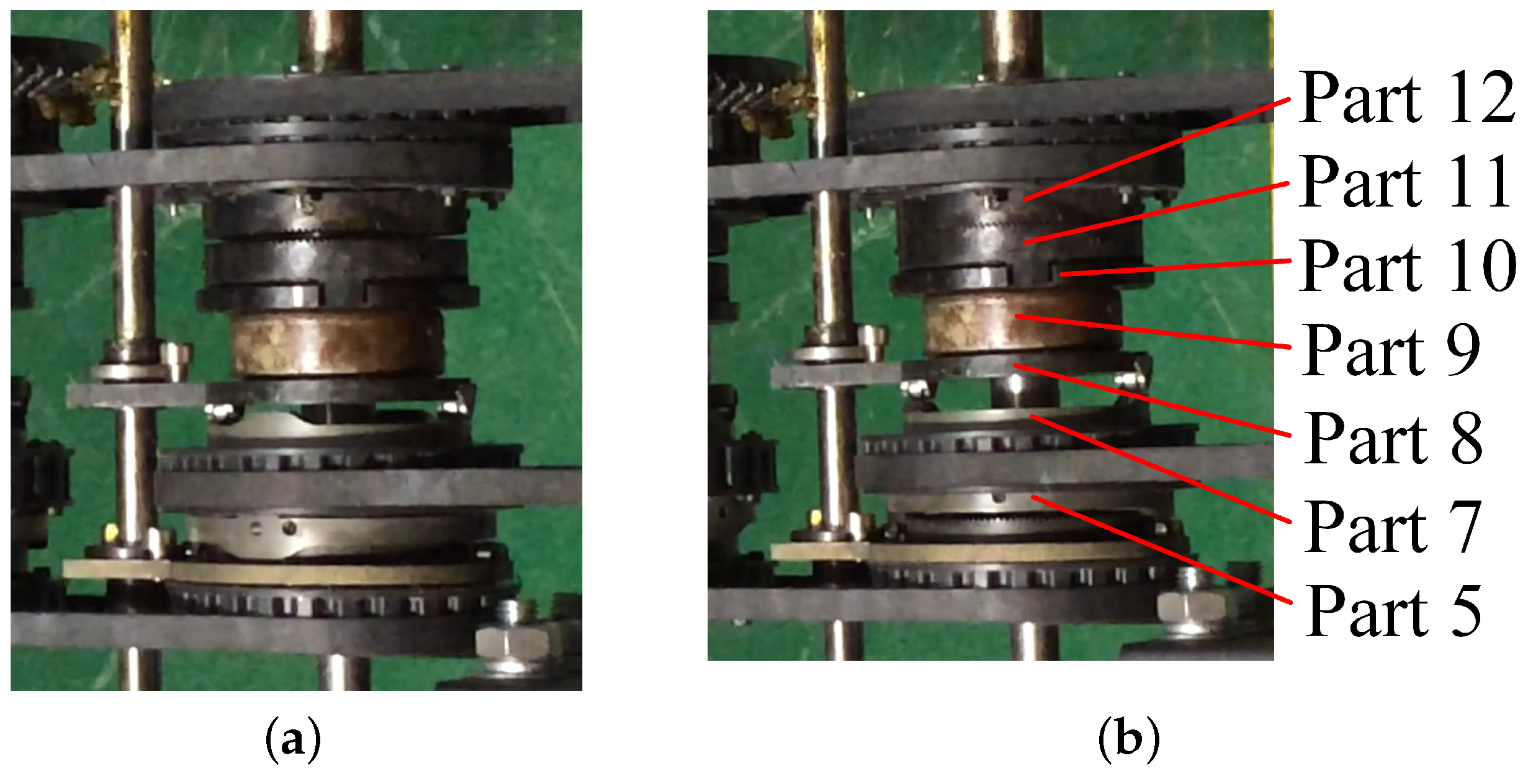
3.2.1. Experiment of the PSU
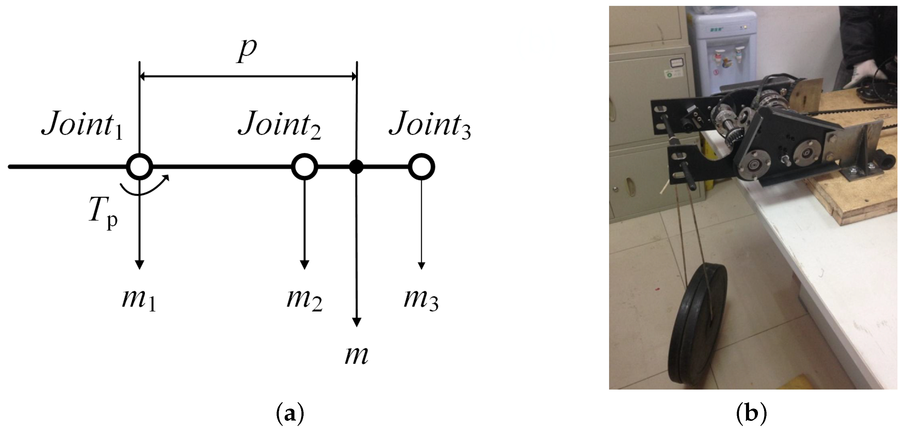
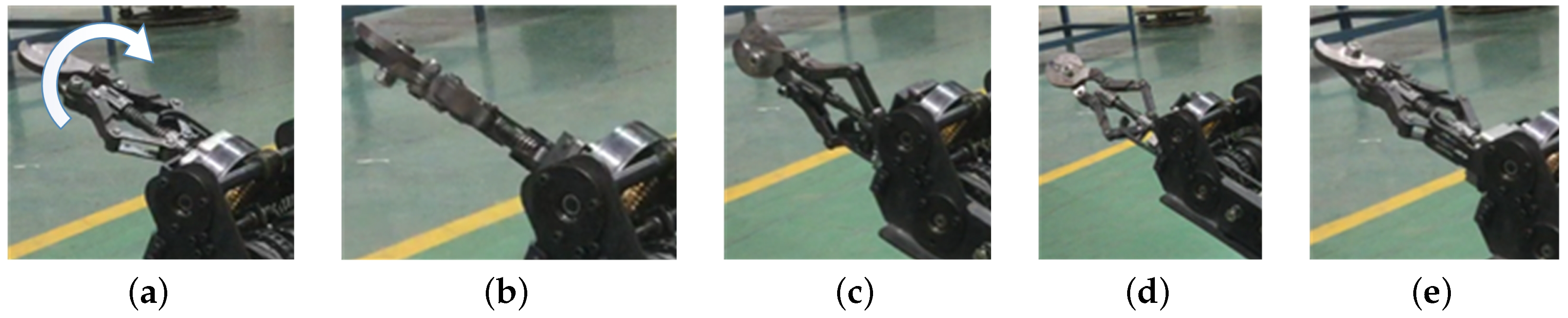
3.2.2. Experiment of the Shoulder Joint

| Items | Values | Units | Items | Values | Units |
|---|---|---|---|---|---|
| 7.5 | kg | p | 0.361 | m | |
| 7.5 | kg | 112.5 | Nm | ||
| 5.5 | kg | −20 to 90 | deg | ||
| m | 20.5 | kg |
3.2.3. Experiment of the Wrist Joint
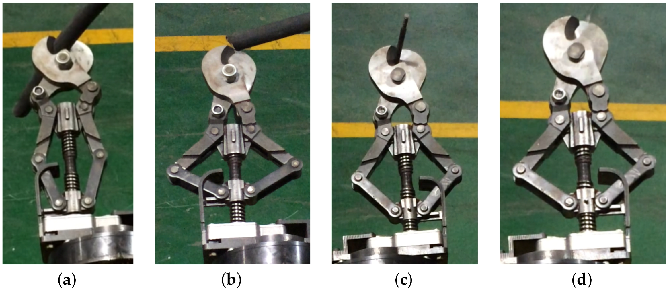
3.2.4. Experiment of the Scissors Joint
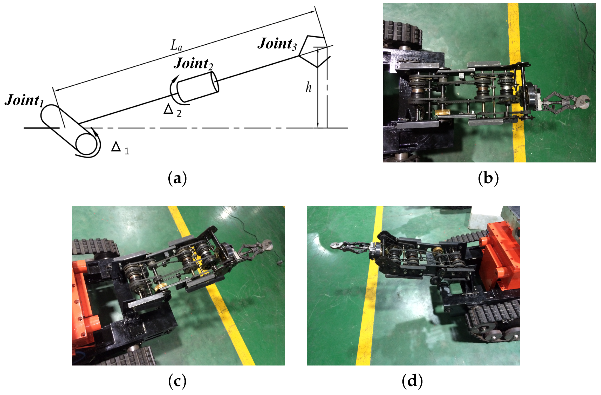
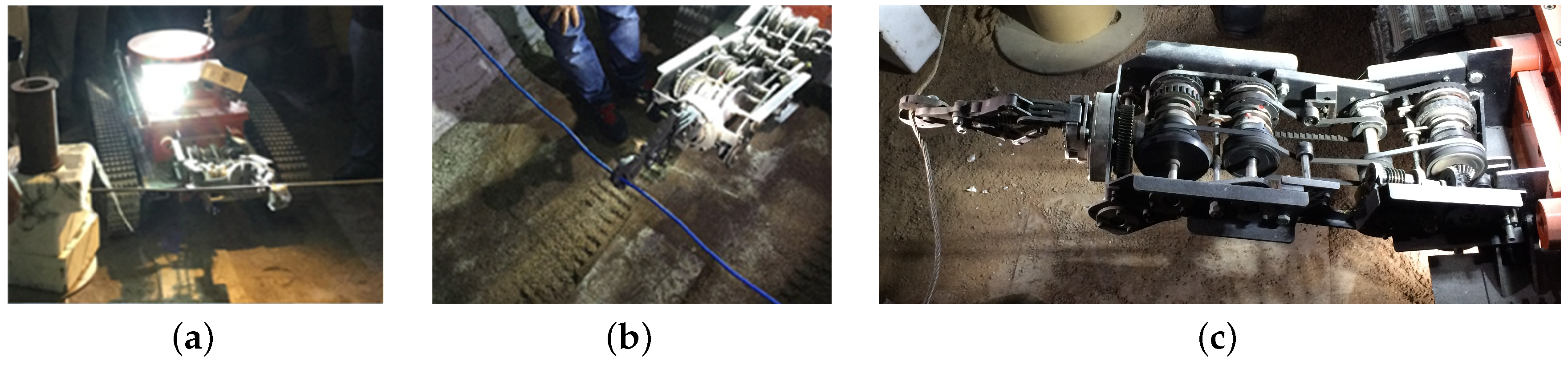
3.2.5. Experiment of the Manipulator
3.3. Summarized
- The belts and pulleys used for the manipulator are made of flame-retardant rubber and nonmetallic material which are tested as antistatic materials, and all the other parts are made of steel. As such, the manipulator can ensure security when working in an explosive environment.
- The manipulator is mounted on a robot chassis for cleaning obstacles. It can be swung left and right by the mobile chassis turning left and right. So, it will help the scissor to conveniently aim at targets.
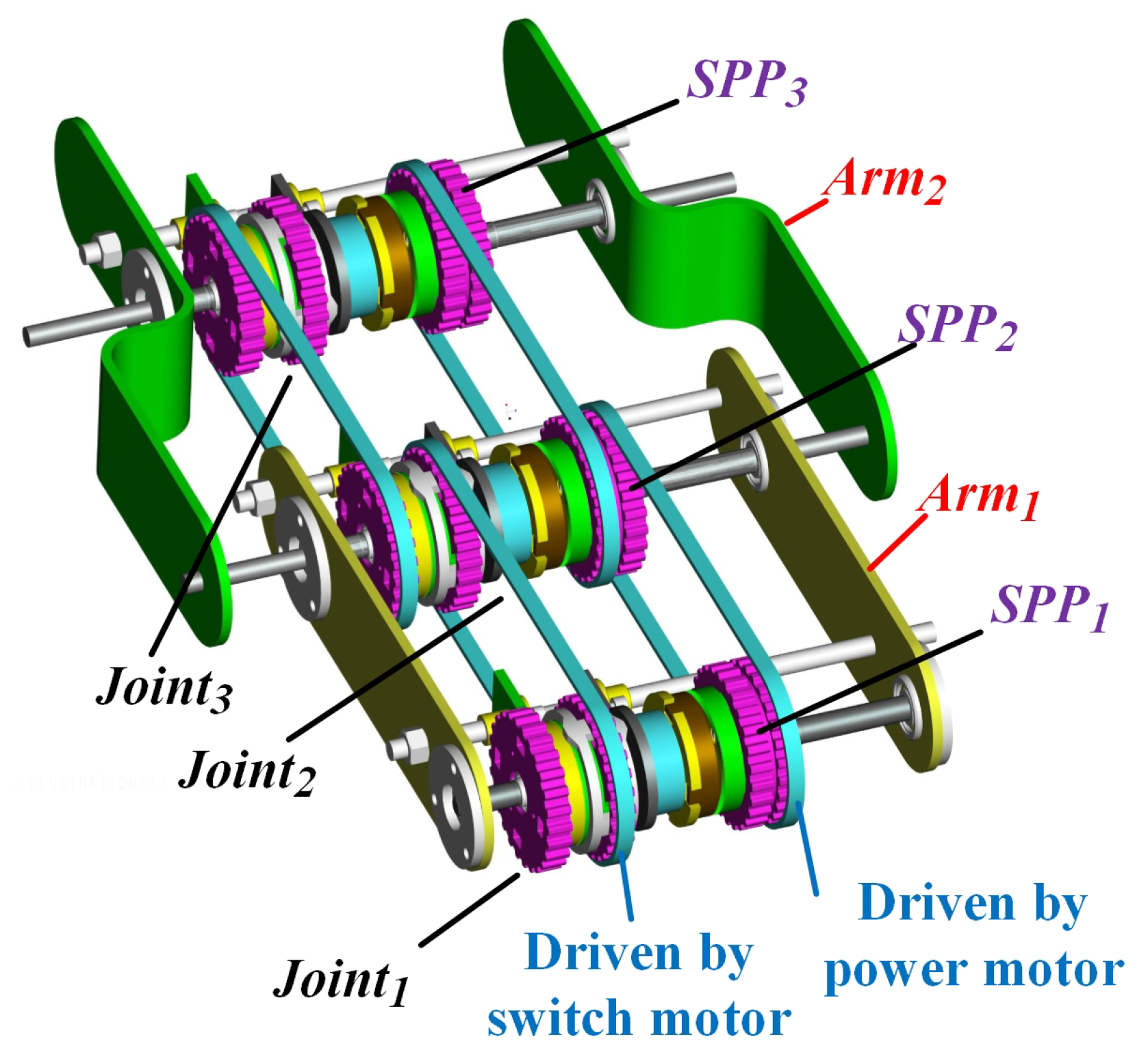
- The three manipulator joints in our paper are not parallel, as shown in Figure 18a. The shoulder joint and wrist joint are orthogonal, and the wrist joint and scissors joint are also not parallel, because the scissors are a linkage mechanism. Then, the shoulder joints can be added easily, because they are parallel joints (the adding method can be seen in Figure 10). The wrist joint cannot be added easily among shoulder joints. The scissor joint does not need to added.
- The switch motor and power motor are separated from the manipulator and assembled on the mobile chassis and their weights are 5.5 kg and 12 kg together with their explosive-box. So, the effect of reducing the manipulator weight by the design method proposed in this paper is obvious. In addition, the motor cables for driving manipulator joints are not assembled on the manipulator. If every joint had a driving motor, the cable of the scissors joint motor would catch fire and the battery would be destroyed when the scissors work in a high temperature environment.
- The manipulators that used the pneumatic drive method will be loose because the gas in the pneumatic cylinder can be compressed like a spring when the robot chassis is moving, which will make it difficult for the scissors joint to aim at the targets. On the other hand, the gas discharged by the pneumatic cylinder may influence the explosive environment. The manipulators that used the hydraulic drive method should protect their hydraulic tubing from being seriously damaged when they work in a high temperature environment. Furthermore, the assembly of the hydraulic pump is a big problem for designers. Therefore, the manipulator in this paper can be more conveniently and securely assembled on a robot or other mobile chassis than others that used the pneumatic and hydraulic drive method.
3.4. Practical Procedure
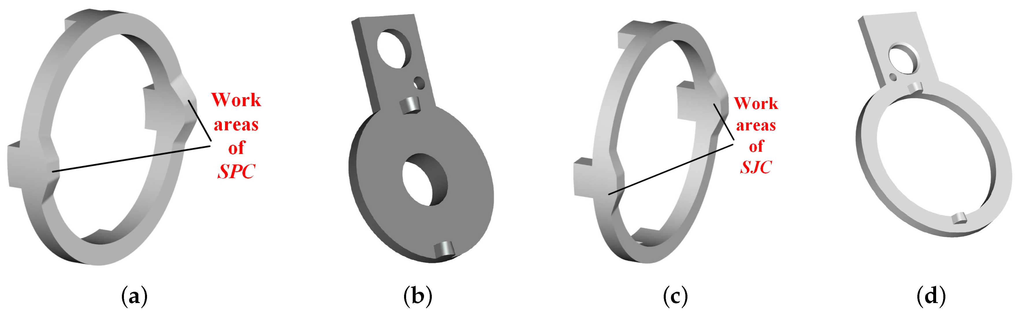
- Design the PSU for transmitting and switching power among joints of the manipulator; the work radius of clutches SJPM and SJPS in this paper is determined by the cams’ SJC and SPC requirements; it can be changed according readers’ environment requirements.
- Design the cams’ SJC and SJC for switching on/off the power and separating from the next arm of the manipulator.
- Accumulate the spring stiffness , and of the PSU.
- Design the mechanical transmission mechanism for the whole manipulator.
4. Discussion
- The height of the manipulator prototype can be reduced by reducing the volumes of the PSU and the other parts, such as the worm component and bevel gears.
- When the SJC is pushed by SJF, the phase difference will occur if SJC does not return along the original direction. So, the controller should plan the switch program to compensate for the phase difference.
- If the manipulator adds a shoulder joint as a pitch joint between the shoulder joint and wrist joint ( and ), the pitching angle of the scissors can be adjusted and can aim at valves for opening and closing.
- The three joints cannot move at the same time. If they could, the motion among the three joints must be constant and they would not be not flexible enough to clean obstacles, such as cables and steel roll bars.
- During the cutting of cables and steel roll bars by scissors, the speed is not quick enough because of the large reduction ratio. In order to clean obstacles powerfully, the cutting speed can be considered secondary. However, it will be improved in future work.
- The scissors joint can replace other tools for cleaning obstacles, and it will be designed for switch valves to carry out search-and-rescue in gas-leak environments.
5. Conclusions
6. Patents
Author Contributions
Acknowledgments
Conflicts of Interest
Abbreviations
| PSU | Power Switch Unit |
| Power motor | The motor for supplying the power for joint rotation. |
| Switch motor | The motor for switching power among all the joints. |
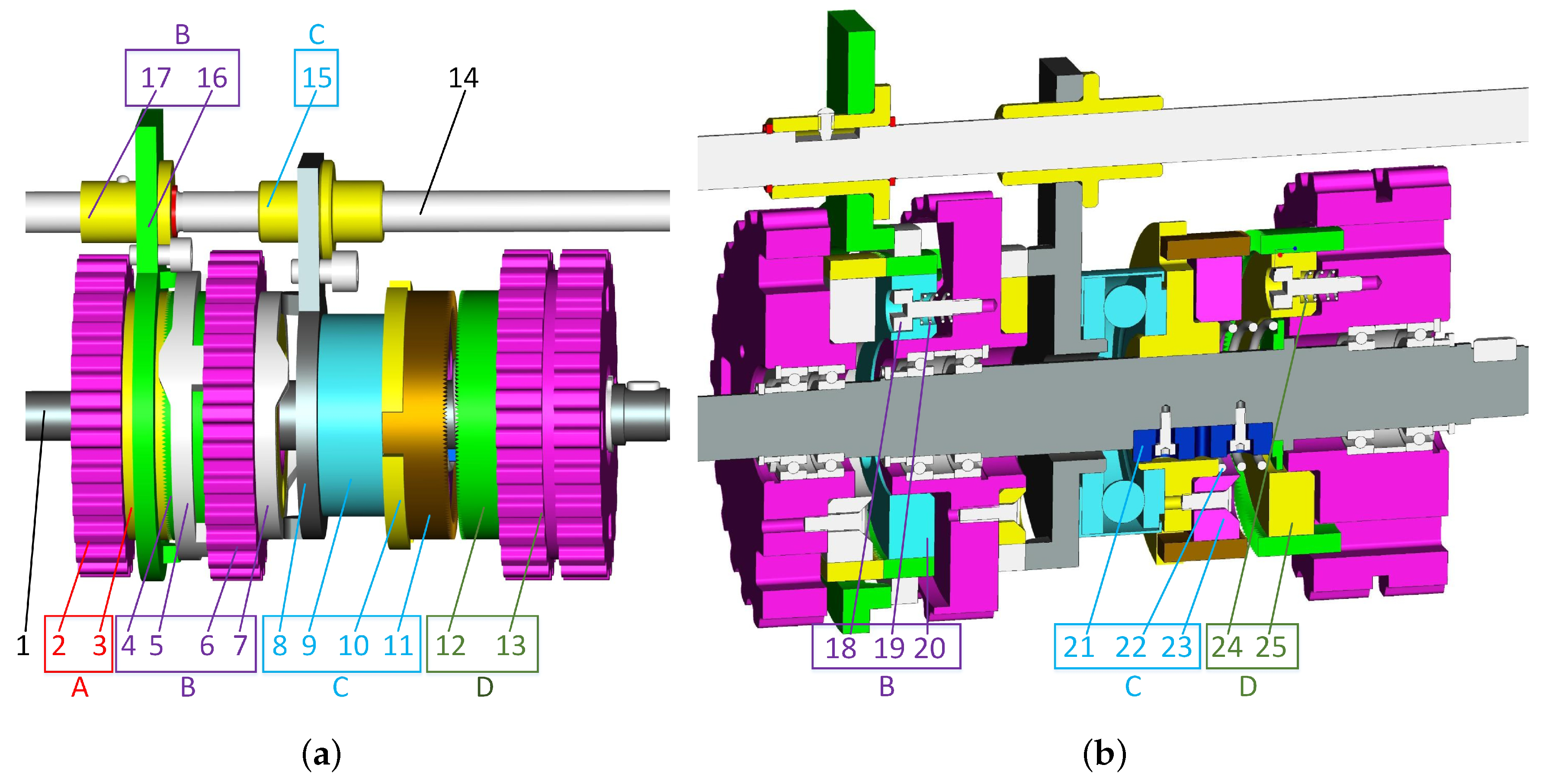
| Group A | The Group A (shown in in Figure 1) are used for switch the power among joints. |
| Group B | The Group B (shown in in Figure 1) are used for switch the power among joints. |
| Group C | The parts in Group C (shown in in Figure 1) are used for transmitting the power from the motor to the current joint. |
| Group D | The parts in Group D (shown in in Figure 1) are used for transmitting the power from the power motor to the current joint. |
| SJC | Part 5 in Figure 1, the cam used for switching power among joints. |
| SJPS | Part 2 in Figure 1, the slave pulley used for transmitting rotation of switch motor. |
| SPC | Part 7 in Figure 1, the cam used for transmitting power to the current joint. |
| SJPM | Part 6 in Figure 1, the master pulley used for switching power among joint. |
| SPF | Part 8 in Figure 1, the cam follower of the Part 7. |
| SJF | Part 16 in Figure 1, the cam follower for the Part 5. |
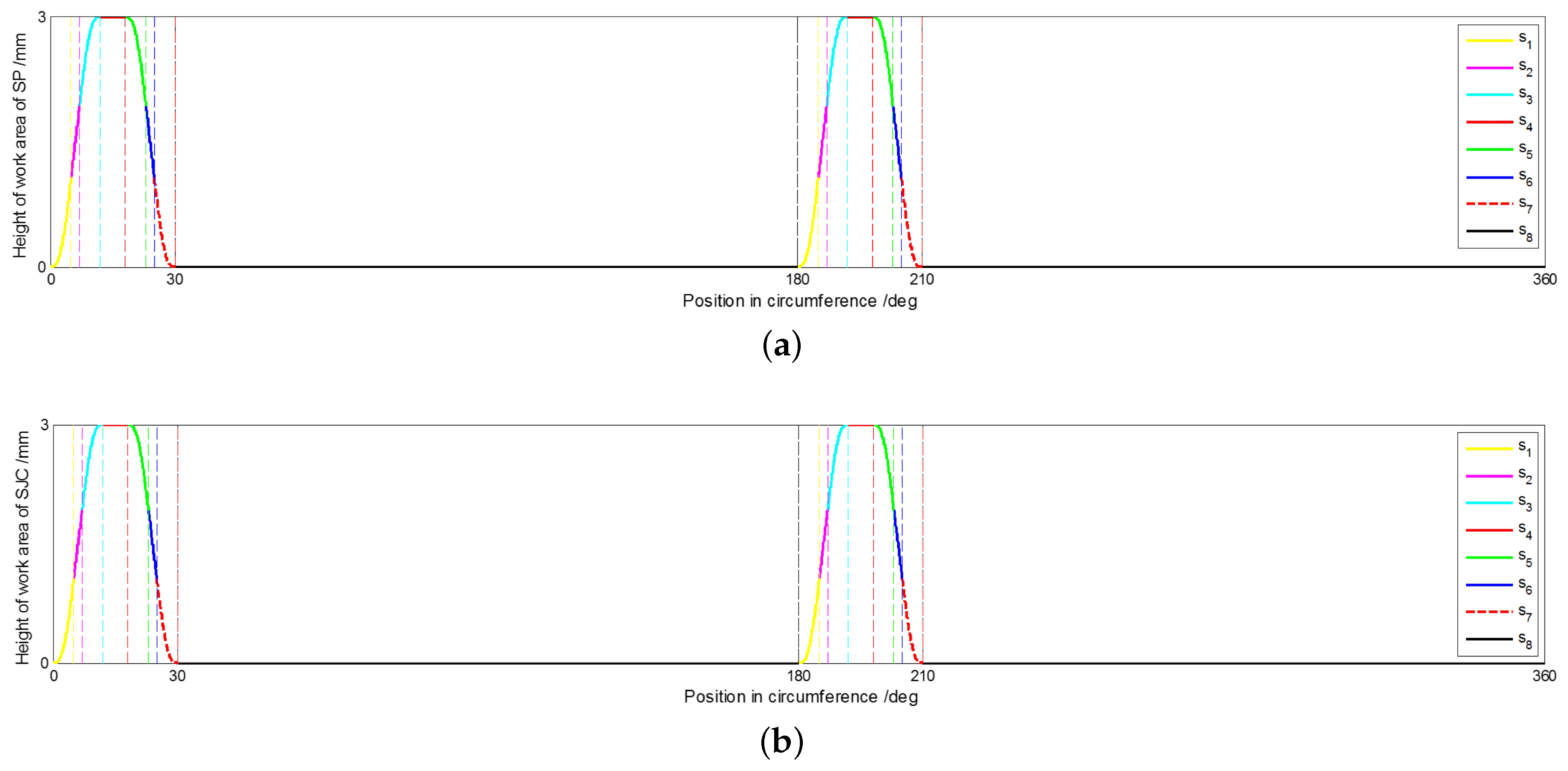
| s | In Equation (1), the height of the cam work area and it is also the linear displacement of the SPC and SJF. |
| – | The height of the cam work area and it is also the linear displacement of the SPC and SJF in the 8 segments. |
| h | The maximum height of the cam wrok area. |
| The maximum height of the and of the cam law curve. | |
| The maximum height of the and of the cam law curve. | |
| The angular position of the cam, in the region of 0 to . | |
| – | The partition point of – segments in whole region. |
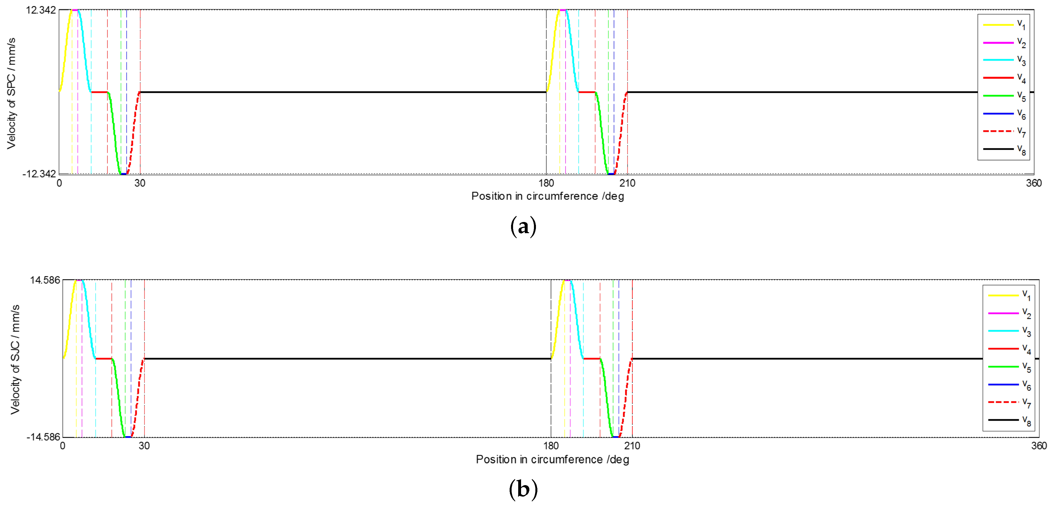
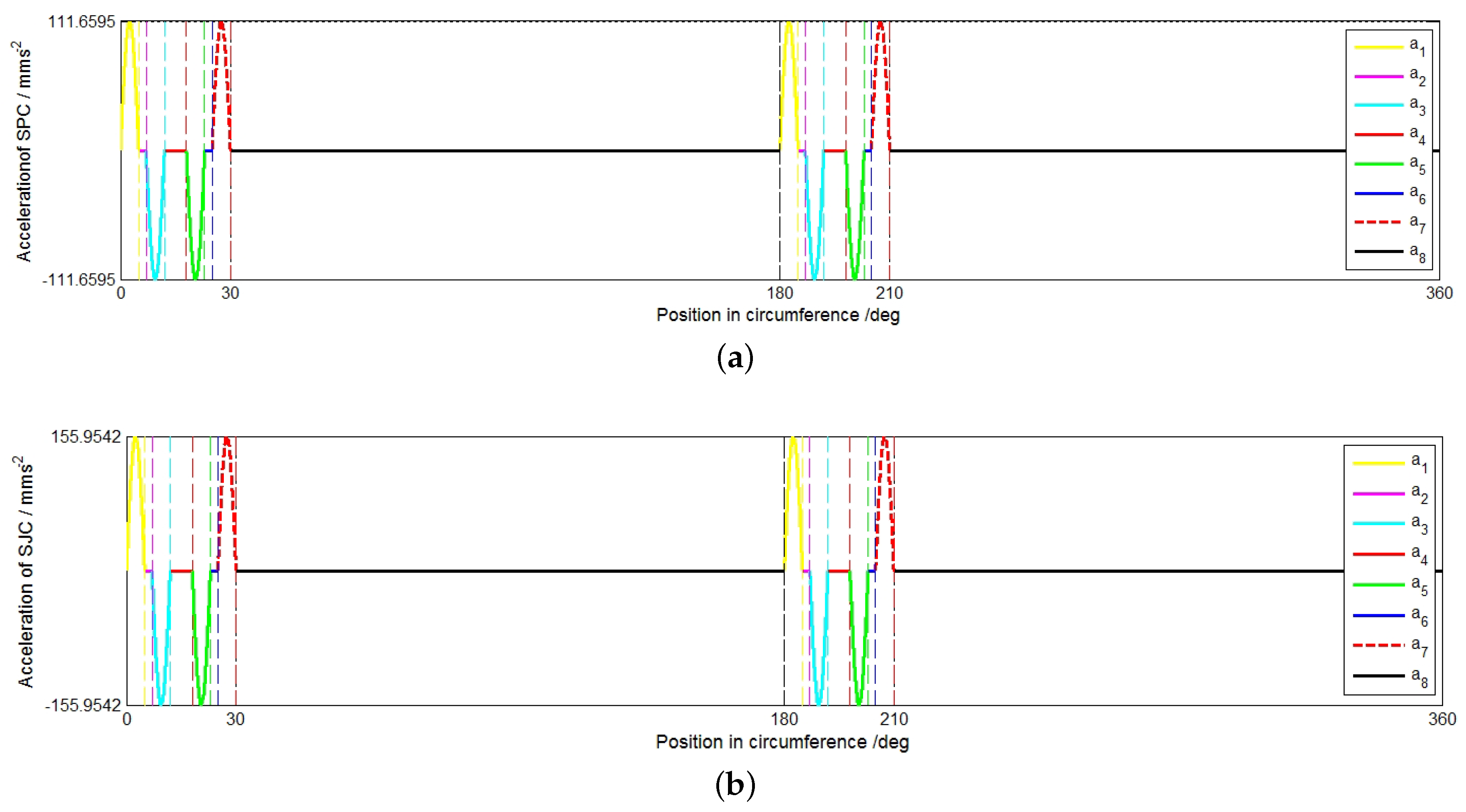
| v | The linear velocitiy of the SPC and SJF along their axis direction. |
| – | The linear velocity of the SPC and SJF in the 8 segments along their axis direction. |
| r | The working radius of the cam. |
| The angular velocity of the cam. | |
| a | The linear acceleration of the SPC and SJF along their axis direction. |
| – | The linear acceleration of the SPC and SJF in the 8 segments along their axis direction. |
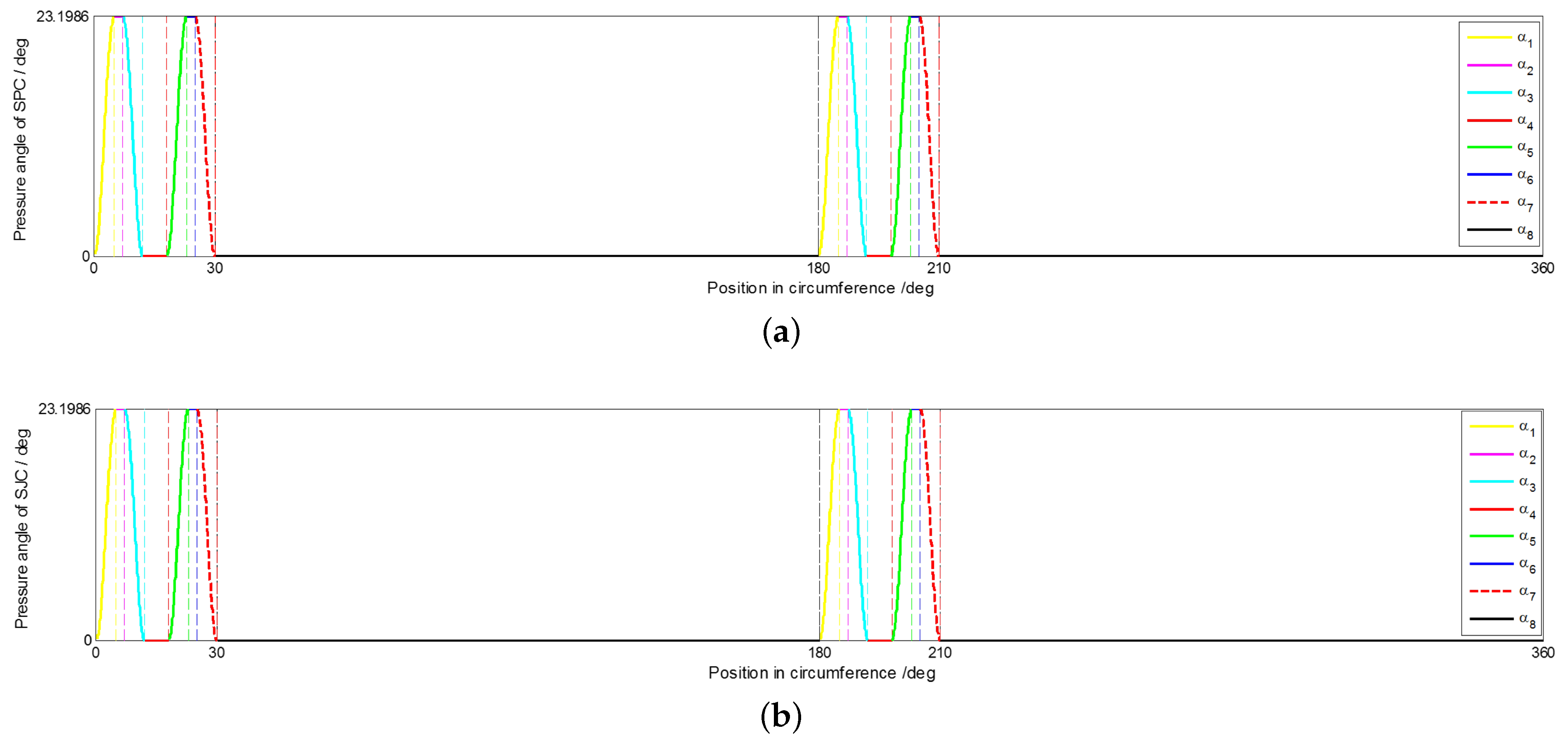
| The pressure angle between the cam its follower. | |
| – | The pressure angle between the cam its follower in the 8 segments. |
| The force of SPF pushed by SPC. | |
| The force of SJC pushed by SJF. | |
| The spring stiffness coefficient of Part 22. | |
| The spring stiffness coefficient of Part 24. | |
| The spring stiffness coefficient of Part 19. | |
| The dynamic friction coefficient between the cam and its followers. | |
| The preload of spring (Part 22) | |
| The preload of Spring (Part 24) | |
| The torque of switch motor for working | |
| The torque of power motor for working | |
| DOF | Degree of Freedom. |
References
- Fukushima Nuclear Disaster Rescue in 2011. Available online: http://www.sanyglobal.com/csr.html (accessed on 20 December 2017).
- Wolf, A.; Choset, H.H.; Brown, B.H.; Casciola, R.W. Design and control of a mobile hyper-redundant urban search and rescue robot. Adv. Robot. 2005, 19, 221–248. [Google Scholar] [CrossRef]
- Wei, B.; Gao, J.; Zhu, J.; Li, K. (Eds.) Design of a Large Explosive Ordnance Disposal Robot. In Proceedings of the 2009 Second International Conference on Intelligent Computation Technology & Automation, Changsha, China, 10–11 October 2009; Volume 3. [Google Scholar]
- Motaleb, A.K.B.; Hoque, M.B.; Hoque, M.A. (Eds.) Bomb disposal robot. In Proceedings of the 2016 International Conference on Innovations in Science, Engineering and Technology (ICISET), Dhaka, Bangladesh, 28–29 October 2016. [Google Scholar]
- Sandia National Laboratories: News Releases: Sandia Labs’ Gemini-Scout Robot Likely to Reach Trapped Miners Ahead of Rescuers. Available online: https://share-ng.sandia.gov/news/resources/news$_$releases\/miner-scou/$#$.WK46z1V95pg (accessed on 26 May 2015).
- Wang, W.; Dong, W.; Su, Y.; Wu, D.; Du, Z. Development of Search-and-rescue Robots for Underground Coal Mine Applications. J. Field Robot. 2014, 31, 386–407. [Google Scholar] [CrossRef]
- Yu-tan, L.; Hua, Z.; Meng-Gang, L.; Peng, L. A novel explosion-proof walking system: Twin dual-motor drive tracked units for coal mine rescue robots. J. Cent. South Univ. 2016, 23, 2570–2577. [Google Scholar]
- Novák, P.; Babjak, J.; Kot, T.; Olivka, P.; Moczulski, W. Exploration Mobile Robot for Coal Mines. In Modelling and Simulation for Autonomous Systems; Hodicky, J., Ed.; LNCS sublibrary: SL 3—Information Systems and Applications, Incl. Internet/Web, and HCI; Springer: Cham, Switzerland, 2015; Volume 9055, pp. 209–215. [Google Scholar]
- Zhao, J.; Gao, J.; Zhao, F.; Liu, Y. A Search-and-Rescue Robot System for Remotely Sensing the Underground Coal Mine Environment. Sensors 2017, 17, 2426. [Google Scholar] [CrossRef] [PubMed]
- Kamezaki, M.; Hashimoto, S.; Iwata, H.; Sugano, S. (Eds.) Development of a dual robotic arm system to evaluate intelligent system for advanced construction machinery. In Proceedings of the 2010 IEEE/ASME International Conference on Advanced Intelligent Mechatronics, Montreal, QC, Canada, 6–9 July 2010. [Google Scholar]
- Liyanage, M.H.; Krouglicof, N.; Gosine, R. (Eds.) Design and control of a high performance SCARA type robotic arm with rotary hydraulic actuators. In Proceedings of the 2009 Canadian Conference on Electrical and Computer Engineering, St. John’s, NL, Canada, 3–6 May 2009. [Google Scholar]
- PLC Control for Pneumatic Pick and Place Robot-YouTube. Available online: https://www.youtube.com/watch?v=8ZiVKduLUkY (accessed on 16 August 2015).
- Maeda, S.; Tsujiuchi, N.; Koizumi, T.; Sugiura, M.; Kojima, H. Development and Control of a Pneumatic Robot Arm for Industrial Fields. Int. J. Adv. Robot. Syst. 2012, 9, 59. [Google Scholar] [CrossRef]
- Tondu, B.; Ippolito, S.; Guiochet, J.; Daidie, A. A Seven-degrees-of-freedom Robot-arm Driven by Pneumatic Artificial Muscles for Humanoid Robots. Int. J. Robot. Res. 2005, 24, 257–274. [Google Scholar] [CrossRef]
- The Robot-Arm Prosthetic Controlled by Thought-YouTube. Available online: https://www.youtube.com/watch?v=sk1NkWl$_$W2Y (accessed on 12 November 2015).
- Madhani, A.J. Robot Hand with Humanoid Fingers. U.S. Patent No. 8,052,185, 14 October 2011. [Google Scholar]
- Yoshida, K.; Hashizume, K.; Abiko, S. (Eds.) Zero reaction maneuver: Flight validation with ETS-VII space robot and extension to kinematically redundant arm. In Proceedings of the Proceedings 2001 ICRA IEEE International Conference on Robotics and Automation (Cat. No.01CH37164), Seoul, Korea, 21–26 May 2001; Volume 1. [Google Scholar]
- Kasprzyczak, L.; Trenczek, S.; Cader, M. Robot for monitoring hazardous environments as a mechatronic product. J. Autom. Mobile Robot. Intell. Syst. 2012, 6, 57–64. [Google Scholar]
- Yu, Z.; Huang, Q.; Ma, G.; Chen, X.; Zhang, W.; Li, J.; Gao, J. Design and Development of the Humanoid Robot BHR-5. Adv. Mech. Eng. 2014, 6, 852937. [Google Scholar] [CrossRef]
- Today’s Technology Needs Tomorrow’s Heroes-YouTube. Available online: https://www.youtube.com/watc\h?v=xqriTomnOeI (accsessed on 5 July 2015).
- Russia: EMERCOM Enlist Robots to Help After Vorkuta Mine Explosions-YouTube. Available online: https://www.youtube.com/watch?v=OHH1p3$_$Zs2w (accessed on 29 February 2016).
- Beira, R.; Clavel, R.; Bleuler, H. Mechanical Manipulator for Surgical Instruments. U.S. Patent Application No. 13/878,924, 14 November 2013. [Google Scholar]
- Salisbury, J.K.; Townsend, W.T. Compact Cable Transmission with Cable Differential. U.S. Patent No. 5,207,114, 4 May 1993. [Google Scholar]
- Robot Arm on How It’s Made-YouTube. Available online: https://www.youtube.com/watch?v=tkDbmWAy\HYw (accessed on 3 March 2008).
- ABB Robotics-Weldguide IV-YouTube. Available online: https://www.youtube.com/watch?v=80cNPwtKH7\A (accessed on 21 March 2016).
- De Straete, H.J.; Degezelle, P.; De Schutter, J.; Belmans, R.J.M. Servo motor selection criterion for mechatronic applications. Appl. Sci. Technol. 2001, 3, 43–50. [Google Scholar] [CrossRef]
- Giberti, H.; Cinquemani, S.; Legnani, G. Effects of transmission mechanical characteristics on the choice of a motor-reducer. Mechatronics 2010, 20, 604–610. [Google Scholar] [CrossRef]
- Roos, F.; Johansson, H.; Wikander, J. Optimal selection of motor and gearhead in mechatronic applications. Mechatronics 2006, 16, 63–72. [Google Scholar] [CrossRef]
- Buscarino, A.; Fortuna, L.; Frasca, M.; Rizzo, A. Dynamical network interactions in distributed control of robots. Chaos Interdiscip. J. Nonlinear Sci. 2006, 16, 015116. [Google Scholar] [CrossRef] [PubMed]
- Zheng, C.; Su, Y.; Mercorelli, P.; Zheng, C.; Su, Y.; Mercorelli, P. A simple fuzzy controller for robot manipulators with bounded inputs. In Proceedings of the IEEE International Conference on Advanced Intelligent Mechatronics, Munich, Germany, 3–7 July 2017; pp. 1737–1742. [Google Scholar]
- Su, Y.; Zheng, C.; Mercorelli, P. A single PD plus gravity compensation control for global asymptotic regulation of robot manipulators with actuator constraints. In Proceedings of the IEEE International Conference on Advanced Intelligent Mechatronics, Munich, Germany, 3–7 July 2017; pp. 130–135. [Google Scholar]


© 2018 by the authors. Licensee MDPI, Basel, Switzerland. This article is an open access article distributed under the terms and conditions of the Creative Commons Attribution (CC BY) license (http://creativecommons.org/licenses/by/4.0/).
Share and Cite
Zhao, J.; Gao, J.; Zhao, F.; Xu, Z.; Liu, Y. A Design Method for Multijoint Explosive-Proof Manipulators by Two Motors. Appl. Sci. 2018, 8, 712. https://doi.org/10.3390/app8050712
Zhao J, Gao J, Zhao F, Xu Z, Liu Y. A Design Method for Multijoint Explosive-Proof Manipulators by Two Motors. Applied Sciences. 2018; 8(5):712. https://doi.org/10.3390/app8050712
Chicago/Turabian StyleZhao, Jingchao, Junyao Gao, Fangzhou Zhao, Zhe Xu, and Yi Liu. 2018. "A Design Method for Multijoint Explosive-Proof Manipulators by Two Motors" Applied Sciences 8, no. 5: 712. https://doi.org/10.3390/app8050712
APA StyleZhao, J., Gao, J., Zhao, F., Xu, Z., & Liu, Y. (2018). A Design Method for Multijoint Explosive-Proof Manipulators by Two Motors. Applied Sciences, 8(5), 712. https://doi.org/10.3390/app8050712