Article

Development of Shallow-Depth Soil Temperature Estimation Model Based on Thermal Response in Permafrost Area

1
Division of Polar Climate Sciences, Korea Polar Research Institute, Incheon 21990, Korea
2
Department of Electronics and Communication Eng., Hanyang University ERICA Campus, 55 Hanyangdaehak-ro, Sanrok-gu, Ansan, Gyeonggi-do 15588, Korea
3
Department of Civil and Environmental Engineering, Incheon National University, Incheon 22012, Korea
*
Author to whom correspondence should be addressed.
These authors contributed equally to this work.
Appl. Sci. 2018, 8(10), 1886; https://doi.org/10.3390/app8101886
Submission received: 12 September 2018 / Revised: 8 October 2018 / Accepted: 9 October 2018 / Published: 11 October 2018
(This article belongs to the Section Environmental Sciences)

Abstract

:
A soil temperature estimation model for increasing depth in a permafrost area in Alaska near the Bering Sea is proposed based on a thermal response concept. Thermal response is a measure of the internal physical heat transfer of soil due to transferred heat into the soil. Soil temperature data at different depths from late spring to the early autumn period at multiple permafrost sites were collected using automatic sensor measurements. From the analysis results, a model was established based on the relationship between the normalized cumulative soil temperatures (CRCST*i,m and CST*ud,m) of two different depths. CST*ud,m is the parameter of the soil temperature measurement at a depth of 5 cm, and CRCST*i,m is the parameter of the soil temperature measured at deeper depths of i cm (i = 10, 15, 20, and 30). Additionally, the fitting parameters of the mathematical models of the CRCST*i,m–CST*ud,m relationship were determined. The measured soil temperature depth profiles at a different site were compared with their predicted soil temperatures using the developed model for the model validation purpose. Consequently, the predicted soil temperatures at different soil depths using the soil temperature measurement of the uppermost depth (5 cm) were in good agreement with the measured results.

1. Introduction

The permafrost areas adjacent to high-latitude coasts around the North or South Poles are significantly influenced by global climate change. Evidence of global warming in these areas has been reported in many studies [1,2,3,4,5]. Climate change induces radical changes in northern high-altitude coastal and ocean ecosystems [6,7]. Mankind is no exception to this situation. Some of the impacts of permafrost melting of frozen grounds in high-latitude regions include instability of ground in mountainous areas due to reduced strength of the ground [8]. In Russia, several oil pipelines were destroyed, and many roads and building structures have been in potential danger of failure due to permafrost melting [7,9]. Slopes failure and substantial ground surface settlements were reported [10]. In addition, severe melt of frozen ground increases the number and sizes of glacial lakes due to changes in snow cover, ice, and frozen ground [11]. The melt of frozen ground also changes the biological environment germinating plants on soils; therefore, ecosystems of high-latitude regions vary accordingly [11]. It was reported that the trends of global warming are more pronounced for ground temperature increases rather than for atmospheric air temperature increases [8]. Ground temperature increases during summer are significant compared with those in other seasons [12]. The measurement of the depth profile of ground temperature during the period of permafrost active layer development enables the exploration of clues to indirectly measure the negative effects of global warming. Lund et al. [13] reported that most studies on underground temperature, energy balance related to smart heat flow, and energy balance in terms of sensible heat flux and latent heat flux were conducted for short periods of time. Depth profiles of the underground temperature during the summer season provide a measure of heat productivity from the geothermal system [14]. Therefore, it can provide important information on changes in the permafrost layer [15]. The depth profile of underground temperature also enables the indirect investigation of CO2 and NH4+ emission patterns from increases in active layer thickness, microbial decomposition, rates of organic matter decomposition, plant growth, drought monitoring, irrigation, and drainage plans. Therefore, an accurate investigation of the underground temperature is crucial in developing environmental simulation models [16,17,18,19,20,21]. An investigation of the depth profile of soil temperature can contribute to studies of global balance of energy and water resources [22].
Soil temperature is also an important indicator of climate change and an essential parameter for geotechnical and geoenvironmental engineering, as well as soil physical, biological, and chemical processes [12,22,23]. However, limited studies on underground temperature variation have been conducted as compared to other environmental factors, such as air temperature or precipitation. This is due to the significant costs and time required to obtain the spatial and temporal variations of underground temperature depth profiles for a wide area [12]. Thus, an accurate and quick soil temperature simulation needs to be developed [24].
There are diverse studies related to soil temperature modeling [25,26,27,28,29,30,31,32,33,34,35,36]. Dakshanamurthy and Fredlund [25] predicted soil water content from a numerical temperature gradient based on a theoretical model. Mahrer and Katan [26] used the albedo, solar radiation, atmospheric density, and radiation rate to estimate underground temperature. Tabbagh et al. [27] calculated spatio-temporal infiltration and volumetric flow from soil temperature observations. Rajver et al. [28] and Pollack et al. [29] assessed design parameters of the “ground source heat pump system” using soil temperature. The spatio-temporal variation of soil temperature was analyzed based on long-term temperature observation data [30]. In addition, Hu and Feng [31] investigated important roles of soil temperature in considering regional weather and the land–air interaction. Bendjoudi et al. [32] calculated the heat transfer and Darcy velocity of the unsaturated alluvial layer based on temperature data obtained from shallow depths. Other researchers [33,34,35,36] expanded the previous studies [25,26,27,28,29,30,31,32] to predict more realistic ground heat transfer using different approaches.
Most studies about soil temperature estimation models succeeded, to some extent, in predicting soil temperature. However, their prediction algorithms are complicated and they have many fitting parameters. Therefore, more practical and efficient soil temperature estimation models are necessary for capturing the spatial variation of underground temperatures for a wide area [37].
Recently, the research on the evaluation of environmental parameters has been actively conducted using a thermal response concept. These studies use cumulative soil temperature and thermal response to estimate soil moisture content [38,39], crop reproduction rates [40], freezing and thawing indices [41], the warming of the permafrost layer [42], the thickness of the permafrost active layer [43], and thermal energy performance from geothermal heat [44]. The use of cumulative soil temperature reflects the thermal response by accounting for the variation in the soil temperature and the soil temperature’s sustained time. Therefore, it provides better measures of time-dependent soil temperature history compared with the maximum and the minimum daily soil temperatures or average soil temperature [45].
In this study, soil temperature depth profiles at test sites in Alaska were obtained and used to develop a method of prompt estimation of lower-depth soil temperature variations based on thermal response. In addition, depth profiles of soil temperature from different locations were measured from late spring to early fall, during which the ground surface temperature exceeds 0 °C, to more realistically understand the dynamic response and spatial variation of soil temperature. The purpose of this study was to use the soil of the uppermost depth, which is easy to measure, to estimate soil temperatures at deeper depths. The lower-depth soil temperature estimation model was developed with a minimum number of fitting parameters, and the validation of the model and its parameters was also conducted.

2. Materials and Methods

2.1. Thermal Response

Cumulative soil temperature (CST) has been proposed as an effective measure of thermal response for thaw depth evaluation and climate change impact potential [46,47]. The cumulative soil temperature (CSTm) for m consecutive days is obtained from integrating the soil temperature (dynamics) over the total collective duration of m days. Therefore, the thermal response is defined as the integration of soil temperature change for m consecutive days
C S T m = t = 1 m ( T t T r e f )  
where t is the time (or duration) in days, m is the number of cumulative days temperature measurements taken, Tt is the daily average soil temperature for day t, and Tref is the reference temperature. In this study, CSTm was incorporated into the thermal response for the development and evaluation of soil temperature prediction using the measured temperature history from 10 May 2015 to 16 October 2015.

2.2. Study Area

The study area is located in the north subarctic region of the Seward Peninsula, Council, Alaska (64° 50.611 N, 163° 42.709 W), as shown in Figure 1. The altitude is approximately 30 m, and the annual mean temperature and precipitation are −3.1 °C ± 14 °C and 258 mm, respectively [48]. According to the literature [48], the soil property of the site was mostly acidic (i.e., the soil pH ranges from 3.90 to 5.02) and most of the soils are fully saturated (i.e., soil moisture content of 100%). The average total carbon and total nitrogen contents of the soil within a depth of 30 cm are 40% and 1.5%, respectively. Ammonium cation (NH4+) concentrations were measured to be much higher than those of nitrate (NO3) at every measured point and depth. The concentration of ammonium (NH4+) ranges from 8.6 µg to 93.1 µg per unit soil mass (1 g), while that of NO3 is negligibly small [49].
From the site investigation of this study, soil colors are grayish brown, black, and reddish brown. Sieve analysis results showed that the fraction ranges of clays, silts, and sands are 6.4%–20.3%, 55.1%–77.3%, and 15.2%–38.6%, respectively, depending on the sampling depth and location. It was noted that the fraction of silt is dominant.
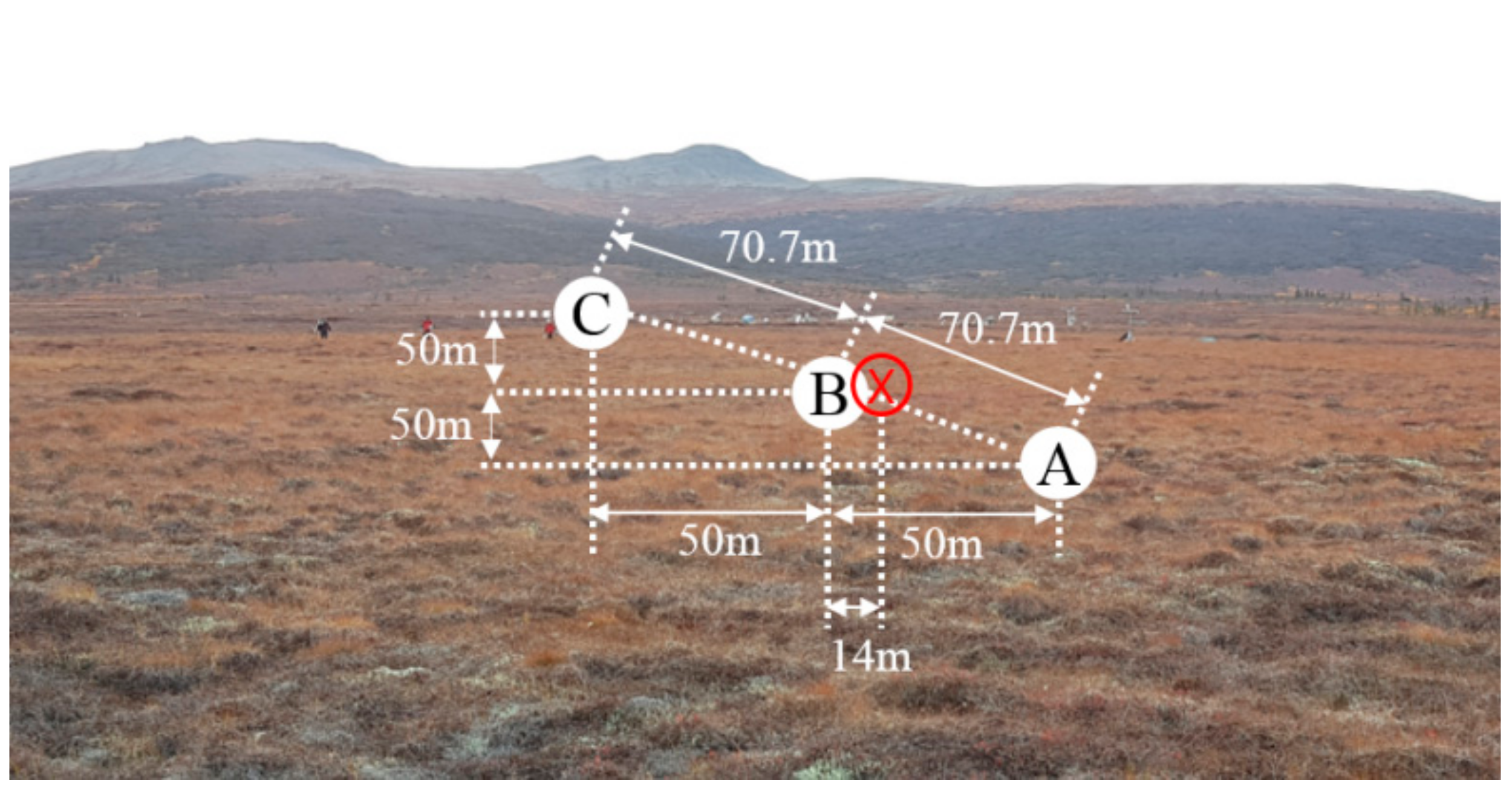
Within the test site in Figure 2, automatic remote sensors of soil temperature measurements were installed at three sites (A, B, and C). The distance between the sites A and B was approximately 70 m. The soil temperatures at each site were measured at different depths of 5, 10, 15, 20, and 30 cm. The soil temperature estimation model was developed based on the data from the sites A and B, while the soil depth profile at the site C was used to validate the developed model. Each point consisted of battery-powered sensor nodes and a flash memory-installed sensor interface circuit (sink node) to remotely store and transmit sensor read data to a receiver (Campbell Scientific 107 Temperature Probe). The air temperature was also measured above 1.2 m from the ground surface within the test sites (the air temperature measurement location is marked “X” in red in Figure 2).

3. Results of the Field Measurements of Soil Temperature

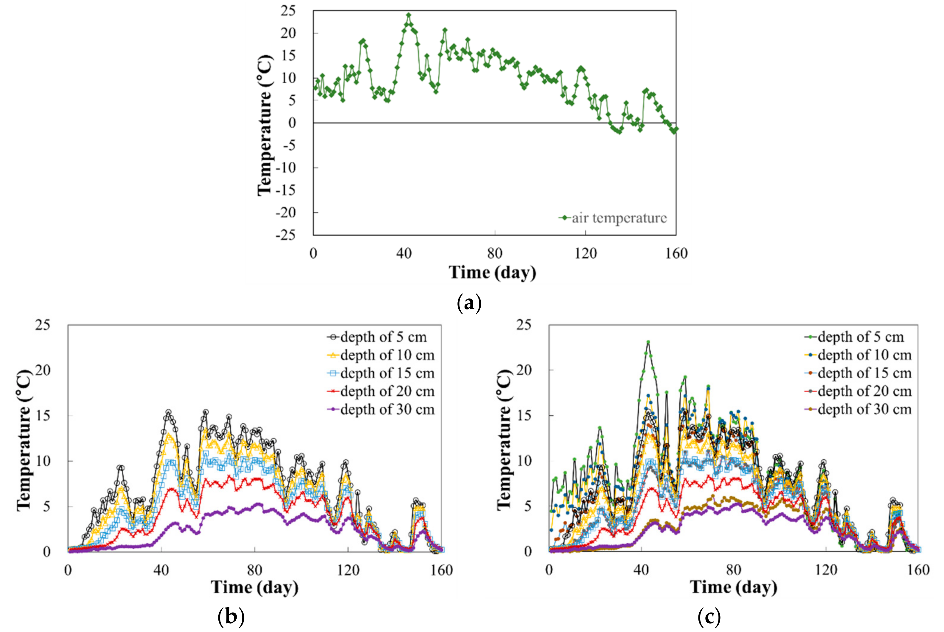
The data measurements from the sensor were recorded every 4 min and were stored in on-board memory. Then, the stored data were transmitted to the remote monitoring center every hour via the iridium satellite network. The soil temperature was measured 160 days from 10 May to 16 October 2015. Figure 3 shows the variations of the daily averages of air temperature at the location “X” and soil temperatures in the sites A and B. Overall, there was a trend where temperatures gradually increased until the 60th day, before decreasing gradually for an additional 90 days. During the soil temperature measurement period, the air temperature was overall above 0 °C, except several days (132th–136th, 144th–145th, and 157th–160th from the start of temperature measurement); however, soil temperatures within the depth range of 5–30 cm were above 0 °C.
From Figure 3, it was observed that the maximum soil temperatures in the sites A and B were different from each other. The reason for this difference between the sites A and B was their differences of soil stratum and heat transfer characteristics. The soil temperature at the uppermost depth from the ground surface showed more drastic variations during the measurement period. The lower-depth soil temperature change was highly governed by the heat change at the soil surface due to variations in radiation and air temperature. Heat from the soil surface transferred into deeper depths. Therefore, soil temperatures of deeper depths were highly influenced by the upper soil temperature. The soil temperature variation tended to decrease with increasing depth. The maximum measured soil temperature decreased with increasing depth. Generally, a little lag in the soil temperature was observed among these points measured at different depths.
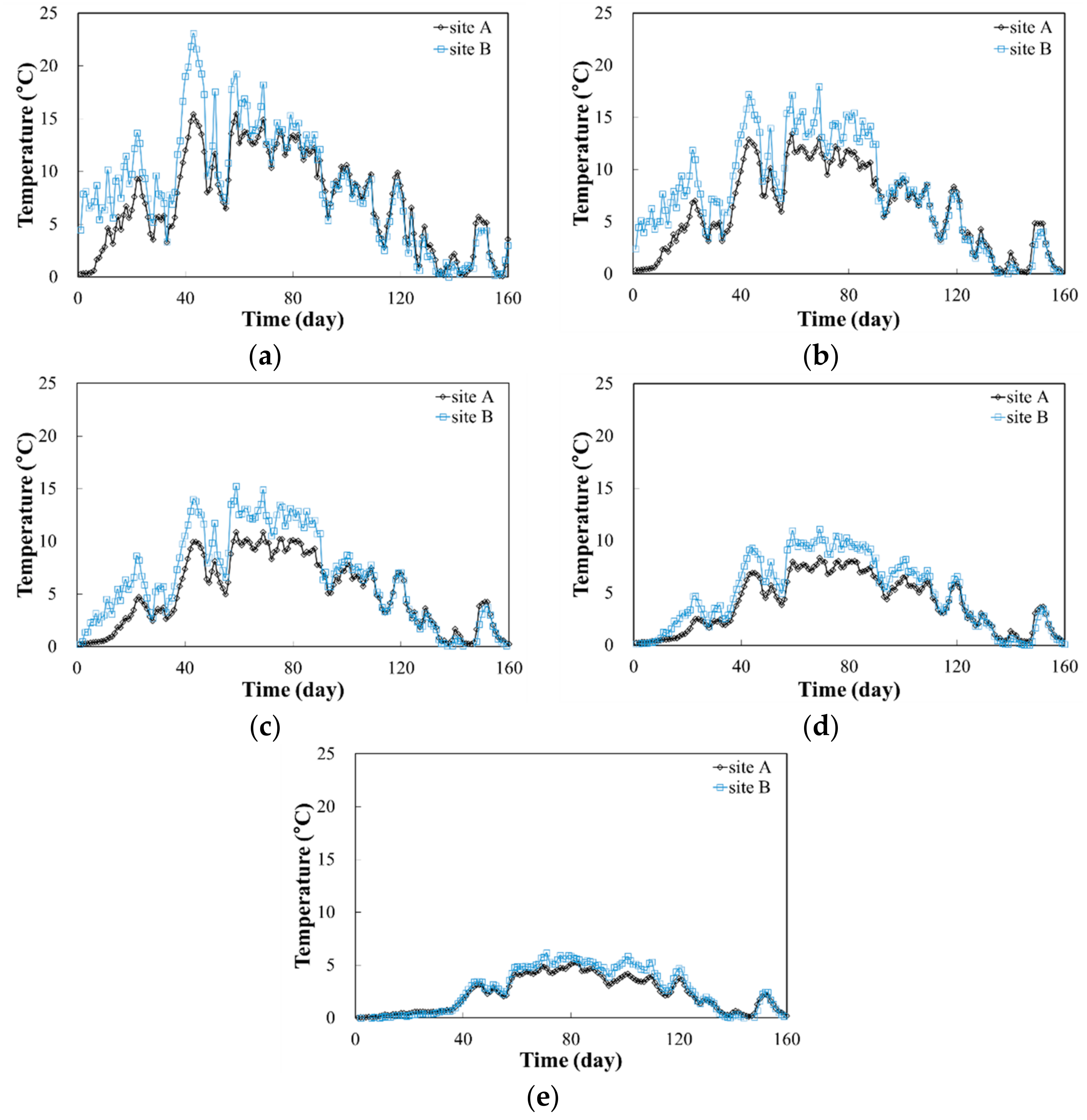
Figure 4 reorganizes the soil temperature time history to group those taken from the same depths in the sites A and B. As is clearly seen from Figure 4, the soil temperature measurements of each site showed different temperature distributions according to different soil properties, such as soil density, thermal conductivity, and others. The time corresponding to the peak daily average soil temperature measurement slightly differed with depth due to the delay of accumulative heat transfer.
For the site A, the highest temperature at the uppermost depth of 5 cm was 15.4 °C. At the remaining depths of 10, 15, 20, and 30 cm, the highest temperatures were measured as 13.4 °C, 10.9 °C, 8.3 °C, and 5.2 °C, respectively. Overall temperatures from the site B were higher than those from the site A. With increasing depth, the measured peak soil temperatures were 23.1 °C, 18.0 °C, 15.2 °C, 11.1 °C, and 6.2 °C, respectively.
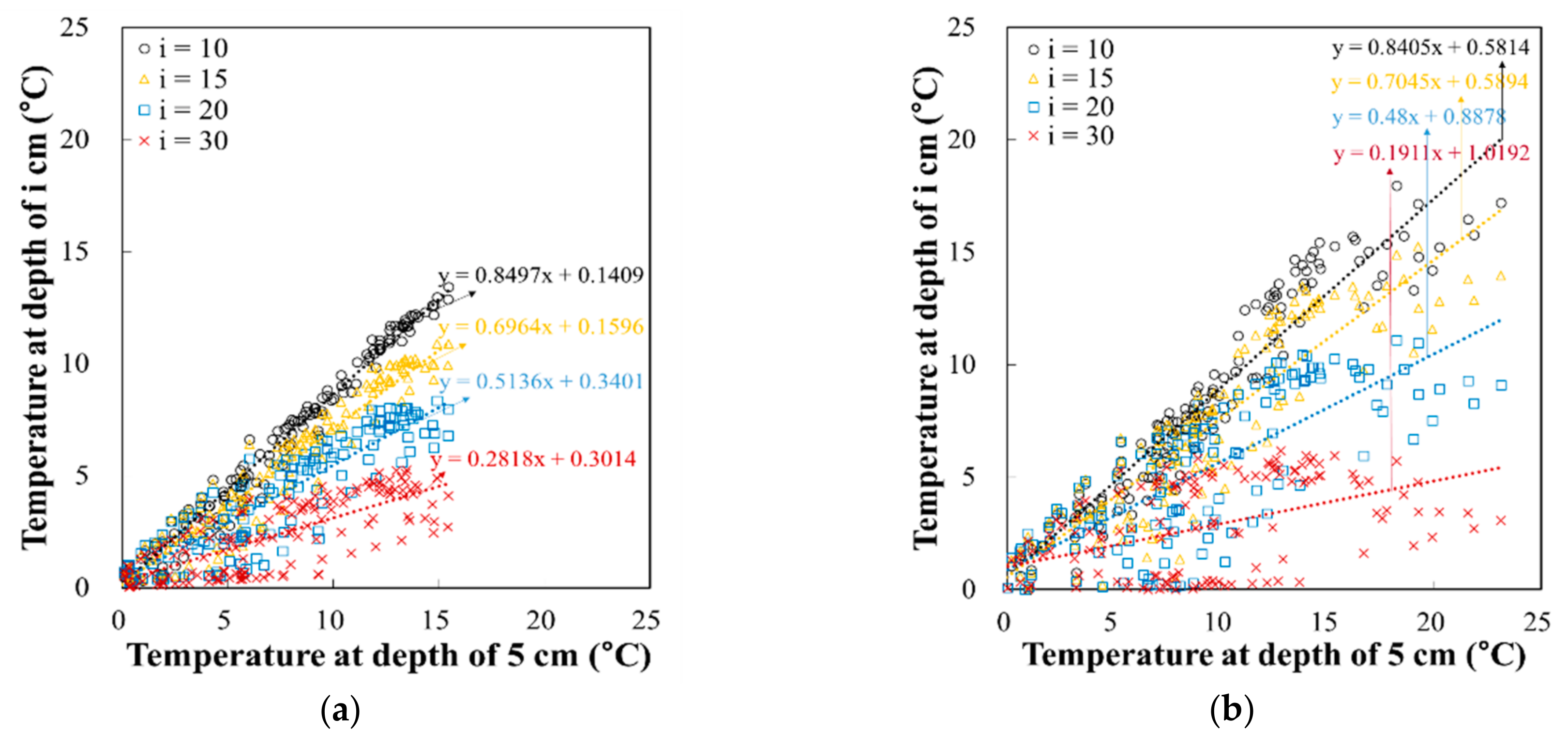
Figure 5 represents the relationships between the soil temperature measured at a depth of 5 cm (Tud), i.e., the uppermost depth considered in this study, and soil temperatures at depths of i cm (i = 10, 15, 20, and 30 cm) (Ti). Due to the scatteredness of points at each site in Figure 5, the relationship between the two measurements (Tud and Ti) could not be described in a simple mathematical form. Additionally, the gradient of Ti increased with increasing depth, while gradient of Tud decreased with increasing depth. This result corresponds to the previous results on air temperature and soil temperature [50,51].
From the soil temperatures at a depth of 5 cm shown in Figure 4a, it is evident that an active layer developed within approximately 160 days (from 10 May to 16 October 2015) as the measured soil temperatures exceeded 0 °C. As the global warming effect is significantly pronounced at high-latitude regions during the period of active soil layer development, the investigation of soil temperature above 0 °C at the uppermost depth of a certain location during this period is useful in modeling the profile of soil temperature. The estimation of the depth profile of soil temperature has a great impact on sensible heat flux, latent heat flux, heat energy productivity, thawing of permafrost layer, patterns of CO2 and NH4 emissions, potential decomposition of microbes, decomposition rates of organic matter, and growth rates of plants [16,17,18,19,20,21].

4. A Soil Temperature Model Based on Thermal Response

4.1. Thermal Response Transfer Process

During the heat transfer from air to soil or that from the soil surface to lower-depth soil due to radiation, lower-depth soils experience temperature variation followed by a change of the thermal response of soil due to heat transfer. During the process (i.e., at the initial moment) of heat transfer, theoretically or conceptually, the soil medium can be classified into two zones: the heat-transferred zone and the heat-untransferred zone. When continuous heat transfer occurs in the soil medium, the heat-transferred zone increases compared to the heat-untransferred zone and eventually, the heat-untransferred zone will diminish. When heat transfer changes in a timely manner, the portions of the heat-transferred zone increase compared to that of the heat-untransferred zone, and their heat changes will have integrated into a thermal response. These thermal responses of soil medium can be alternatively and effectively represented by the cumulative soil temperature. Specifically, soils without temperature change can be defined as having thermal response of zero. This suggests that the transferred zone can be evaluated based on the identification of temperature change, and the degree of thermal response can be assessed from the cumulative soil temperature measured from the reference temperature (i.e., the temperature at the start of measurement or the initial temperature).
From Equation (1), the cumulative soil temperature (CSTud,m) for the uppermost layer (at a depth of 5 cm) for duration of m days can be defined as:
C S T u d , m = t = 1 m ( T u d , t T r e f )  
where Tud,t is the average daily soil temperature at the depth of 5 cm and Tref is assumed as 0 °C in this study.
The normalized cumulative thermal response (CST*ud,m) at the uppermost depth (5 cm) from the start of temperature measurement to time m, in days, can be described as:
C S T * u d , m = C S T u d , m C S T u d , m max = t = 1 m ( T u d , t T r e f ) t = 1 m max ( T u d , t T r e f )  
where mmax is the entire duration of temperature measurement duration (or the entire number of samples of average daily temperature) in days. Then, with respect to the measurement duration of m days, the expected thermal response (RCST*ud,m) at the uppermost level for the rest of the measurement period (i.e., in this study, this is 160 subtracted by m days) can be defined as:
R C S T * u d , m = 1 C S T * u d , m  
The RCST*ud,m indicates the portion of future normalized thermal response, which is deduced using the total potential-normalized thermal response (which is 1−CST*ud,m) and the current normalized cumulative thermal response (CST*ud,m).
Practically, RCST*ud,m can be considered, as the remaining normalized thermal response soils are expected to experience. In other words, if RCST*ud,m is 1, no heat transfer occurs. On the other hand, if RCST*ud,m is 0, heat is completely transferred to the material and a certain temperature is maintained.

4.2. Accumulation of Soil Temperature Characteristics Using CST*ud,m

Dryness [52] defines the concept of soil temperature accumulation in order to effectively analyze the impact of soil temperature change on environmental change. In addition, other researchers [42,53,54] developed an integration-based concept of environmental change. In this study, the following equation of CRCSTi,m, which is a summation of the products of the expected thermal response at m days and the soil temperature at a depth of i cm, was proposed to estimate lower-depth soil temperatures:
C R C S T i , m = t = 1 m R C S T * u d , t ( T i , t T r e f )  
As such, the maximum value of cumulative soil temperature at the depth of i cm (i = 10, 15, 20, and 30) for the entire duration of temperature measurement (mmax) can be denoted as CRCSTi,mmax.
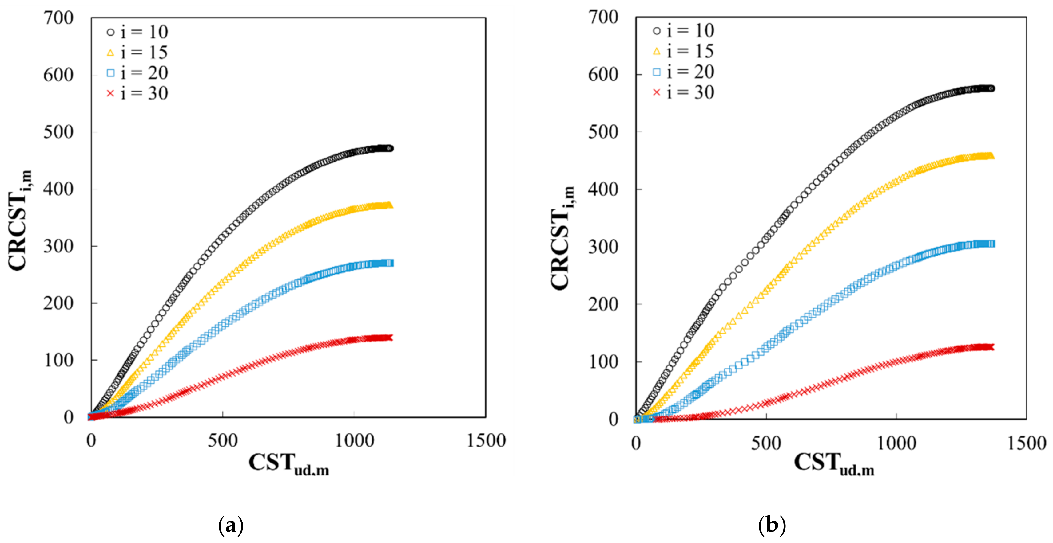
Figure 6 shows the relationships between CSTud,m and CRCSTi,m for the sites A and B. The scattered relationship in Figure 5 between Tdu and Ti can be better alternatively represented by implementing a relationship between CSTud,m and CRCSTi,m. To normalize the relationships of CSTud,m and CRCSTi,m, CRCSTi,m was normalized using CRCSTi,mmax at the same depth for the entire measurement duration (mmax) (Figure 6). For deeper depths of i cm, CRCSTi,m for time m (in days) normalized by CRCSTi,mmax for the entire duration (mmax) was:
C R C S T * i , m = C R C S T i , m C R C S T i , m max  
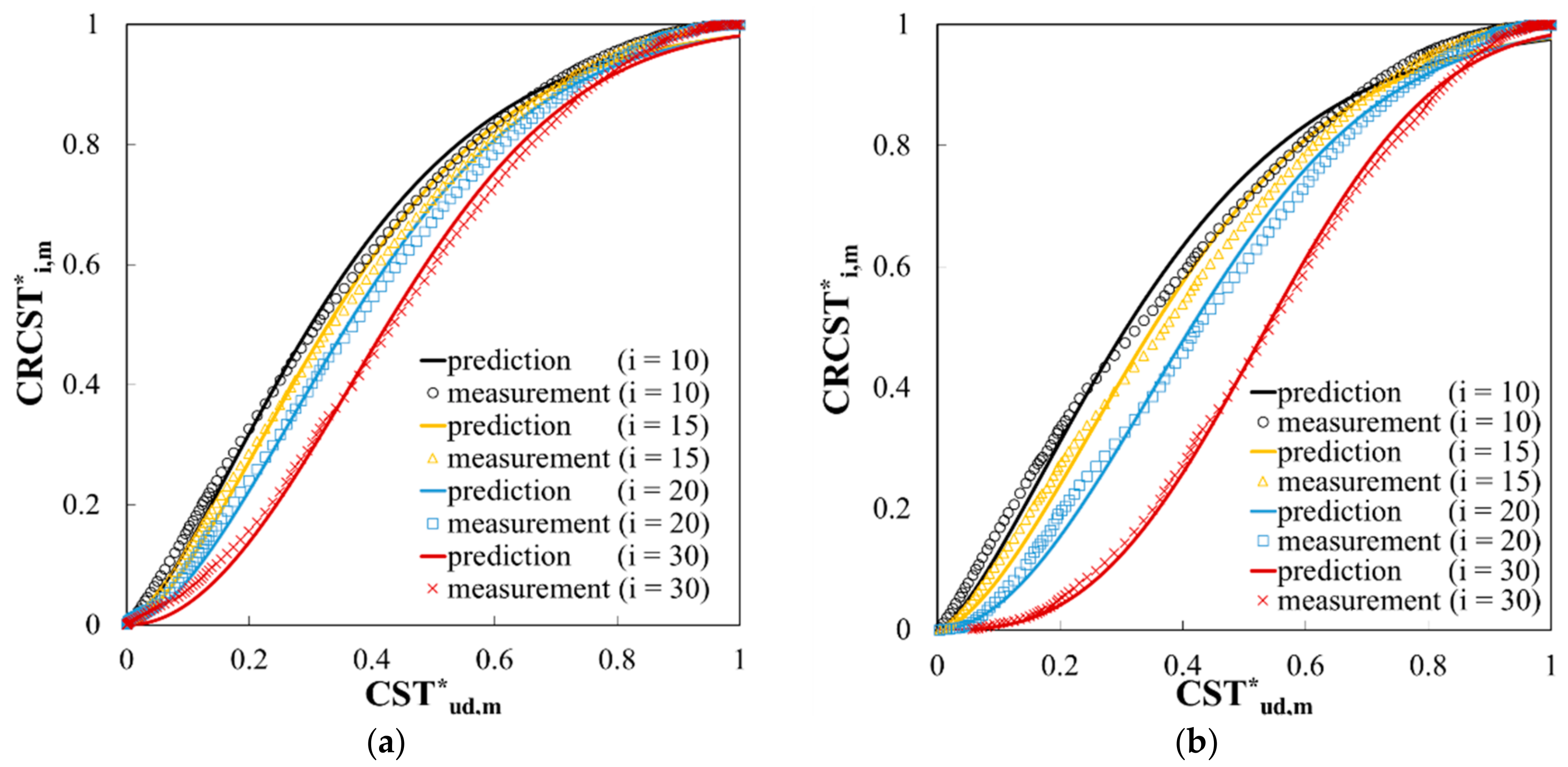
Figure 7 illustrates the relationships between CST*ud,m and CRCST*i,m for the sites A and B using Equation (6). When the Tud–Ti relationships in Figure 5 were compared with the CSTud,m–CRCSTi,m relationships in Figure 6, in particular for soil temperature cases, the results presented in Figure 7 showed improved correlations and appeared to be more suitable for quantifying the temperature relationship between the uppermost layer and deeper layers. Particularly, every curve from the cumulative soil temperature at a depth of 5 cm to the cumulative soil temperature at depths of 10, 15, 20, and 30 cm has an initial gradual rise before converging gradually on a certain point to nearly unite. Accordingly, the relationship in Figure 7 can be illustrated again by using Equations (3) and (6). All the curves in Figure 7 appeared to produce similar shapes, showing unique correlations with soil temperature. The quantification of these correlations is presented below.
As these thermal responses are well represented by their CST*ud,m, a theoretical representation of their correlations was made by normalizing the CST*ud,m of each depth to that of the uppermost depth.

4.3. A Soil Temperature Dynamic Model Using CST*ud,m

As seen from the results in Figure 7, curves representing relationships between CRCST*i,m and CST*ud,m can be closely approximated using the following simple exponential function:
C R C S T * i , m = 1 E X P [ A ( C S T * u d , m ) Z ]  
where A and Z are the fitting parameters. Equation (7) is the Weibull function [55], which is mainly used to increase and decrease processes of soil temperature. Fitting parameters A and Z in Equation (7) represent the scales and overall shapes of the CRCST*i,m and CST*ud,m relationship, respectively. The mathematical difference (Km) between CRCST*i,m and CRCST*i,m−1 can be represented as:
Δ C R C S T * i , m = C R C S T * i , m C R C S T * i , m 1 = E X P [ A ( C S T * u d , m 1 ) Z ] E X P [ A ( C S T * u d , m ) Z ] = K m  
By multiplying the denominator (CRCSTi,mmax) of Equation (3) to all the terms of Equation (8), Equation (8) was modified to:
C R C S T i , m max K m = C R C S T i , m max Δ C R C S T * i , m = C R C S T i , m max ( C R C S T * i , m C R C S T * i , m 1 ) = C R C S T i , m C R C S T i , m 1 = ( T i , m T r e f ) ( R C C S T * u d , m )
Then, the soil temperature at a depth of i cm at time m (in days) was described as:
T i , m = T i , m T r e f = C R C S T i , m max K m ( 1 C S T * u d , m ) 1  
Then, the temperature Ti,m can be assessed based on the values of Km, CRCSTi,mmax, and CST*ud,m.

4.4. Determination of the Fitting Parameters of A and Z to Evaluate CRCSTi,mmax

Using the curve fitting procedure (least squares method), the fitting parameters A and Z of Equation (7) as functions of depth Di were determined from regression analysis. The fitting parameters can be represented by using the following equations:
A = 3.456 ( D i ) 0.957 ( D i ) = 3.456 ( D i ) 0.043  
Z = 0.468 ( D i ) 1.469 / ( D i ) = 0.468 ( D i ) 0.469  
The fitting parameters of sites A and B at different depths are summarized in Table 1. It should be noted that Equations (11) and (12) were used for up to 30 cm of soil depth. Figure 8a,b illustrate the relationships of A/Di and Z Di at a depth of Di. The R2 of the relationships were higher than 0.97.
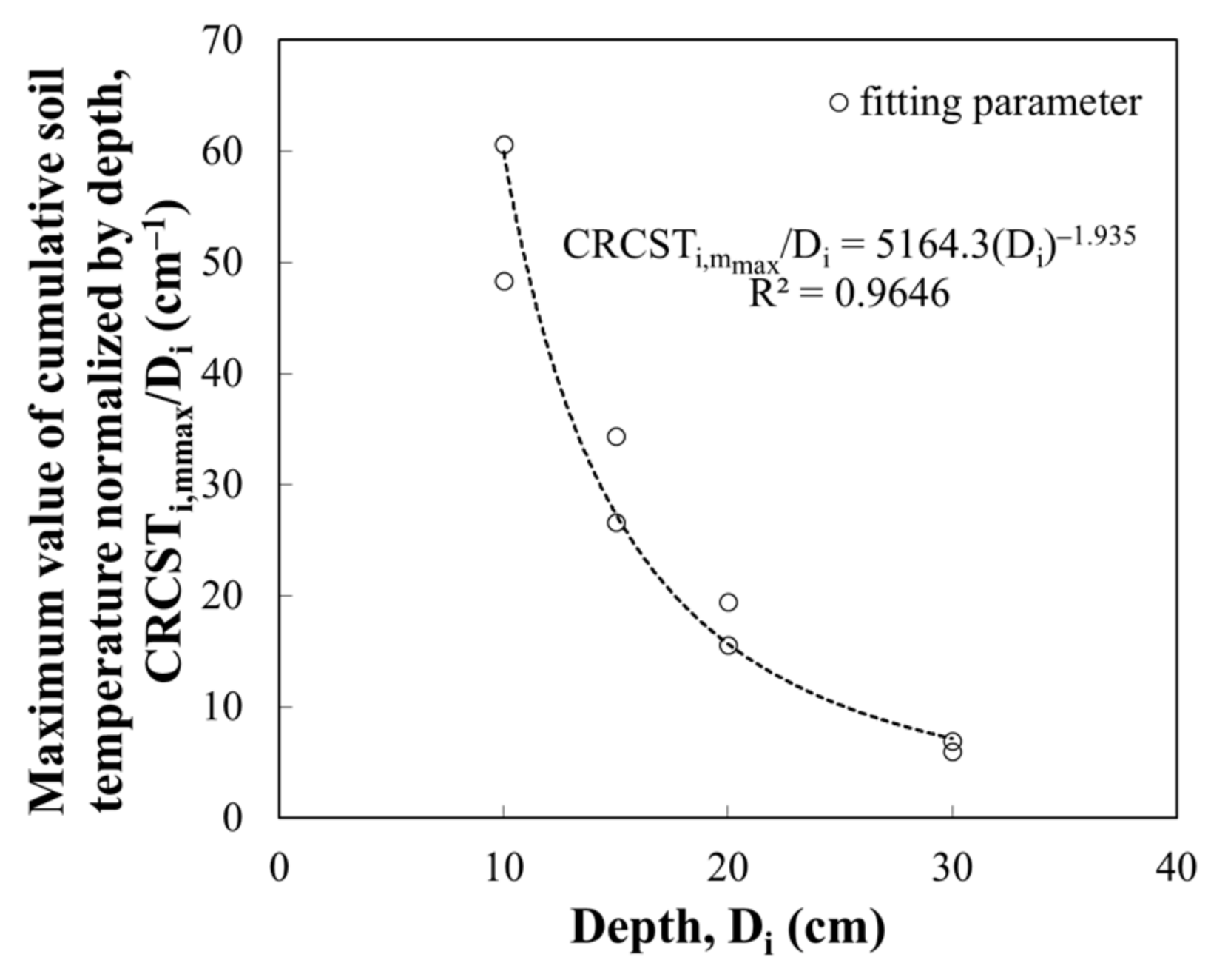
Each value of CRCSTi,mmax can be obtained from a curve fitting process (Table 2). Figure 9 illustrates the values of the parameter CRCSTi,mmax for varying soil depths, which is the normalized value of CRCSTi, mmax (shown in Table 2) divided by the respective soil depth.
Figure 9 shows correlations between the maximum cumulative soil temperature (CRCSTi,mmax/Di) normalized by depth and depth (Di) at a depth of i cm. Since the R2 of the CRCSTi,mmax/Di and Di relationship for different depths was 0.97 or above, the CRCSTi,mmax of each depth can be accurately evaluated when the depth is given. Then, from Equation (12), the CRCSTi,mmax at a depth of i cm was calculated as:
C R C S T i , m max = 5164.3 ( D i ) 1.935 ( D i ) = 5164.3 ( D i ) 0.935  
The fitting parameter of CRCSTi,mmax could be obtained without fully considering soil depth or soil conditions. Accordingly, further testing and investigations were needed.

5. Verification and Comparison of the Developed Lower-Depth Soil Temperature Evaluation Model

5.1. Procedure for the Evaluation of Soil Temperature

The proposed evaluation procedure of lower-depth soil temperature in this study consists of three key steps.
  • Calculate the thermal response of CST*ud,m using Equation (3) and the average daily soil temperature data.
  • Compute the expected thermal response RCST*ud,m at the uppermost level for the rest of the measurement period using Equation (4).
  • Determine the fitting parameters A and Z using Equations (11) and (12) and the maximum cumulative soil temperature CRCSTi,mmax for the entire temperature measurement duration using Equation (13).
  • Determine the soil temperature Ti,m–Tref at the depth of interest based on the calculated CRCST*i,m and ΔCRCST*i,m using Equations (7) and (8), respectively.
The CST*ud,m of input soil temperature can be calculated according to soil temperature time history. Once the CST*ud,m and CRCSTi,m are obtained, the fitting parameters can be given by using Equations (11)–(13). Here, A, Z, and CRCSTi,mmax can be defined for the soil depth. Finally, the soil temperature of a target region can be calculated.

5.2. Experimental Verification of the Developed Lower-Depth Soil Temperature Evaulation Model

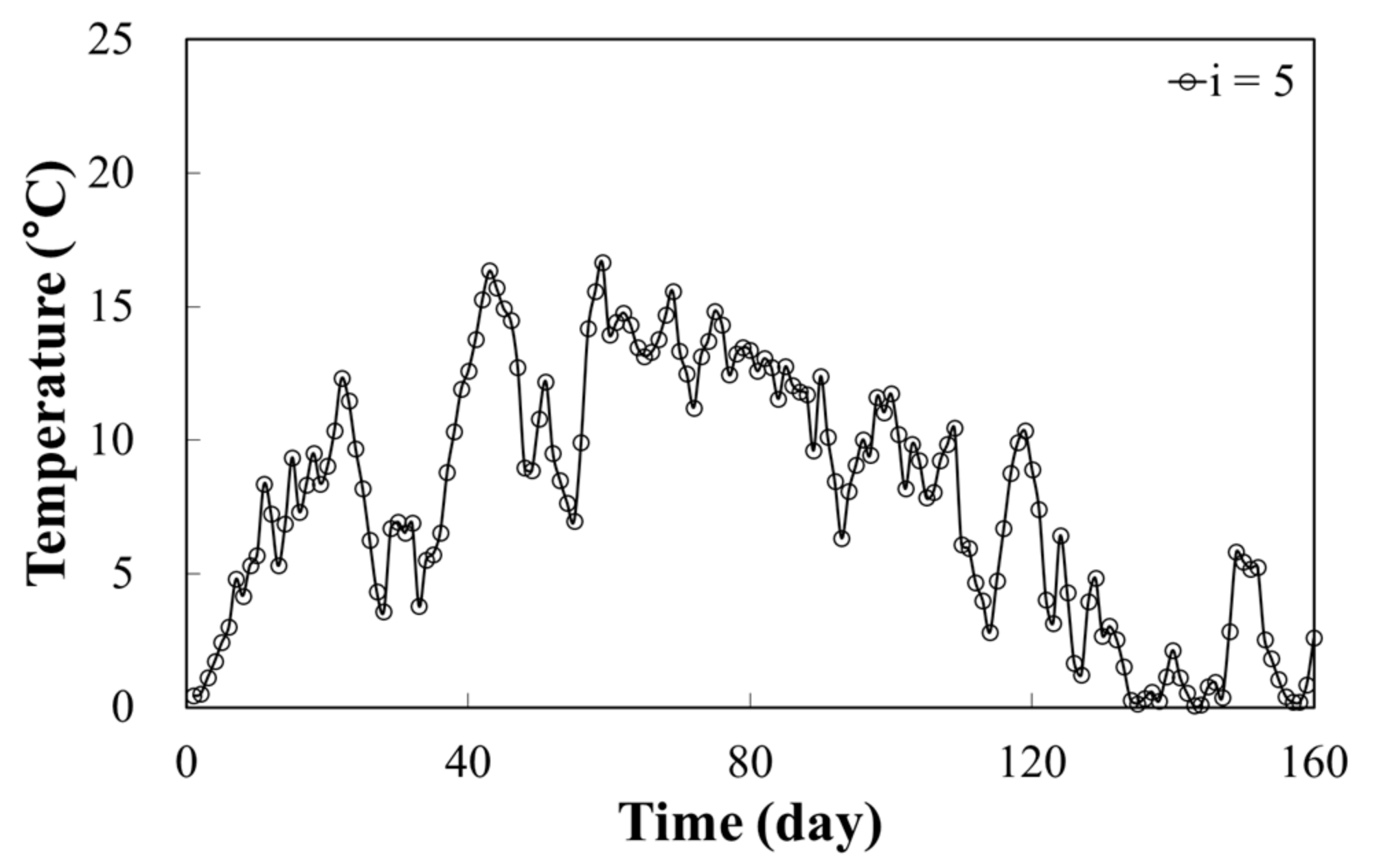
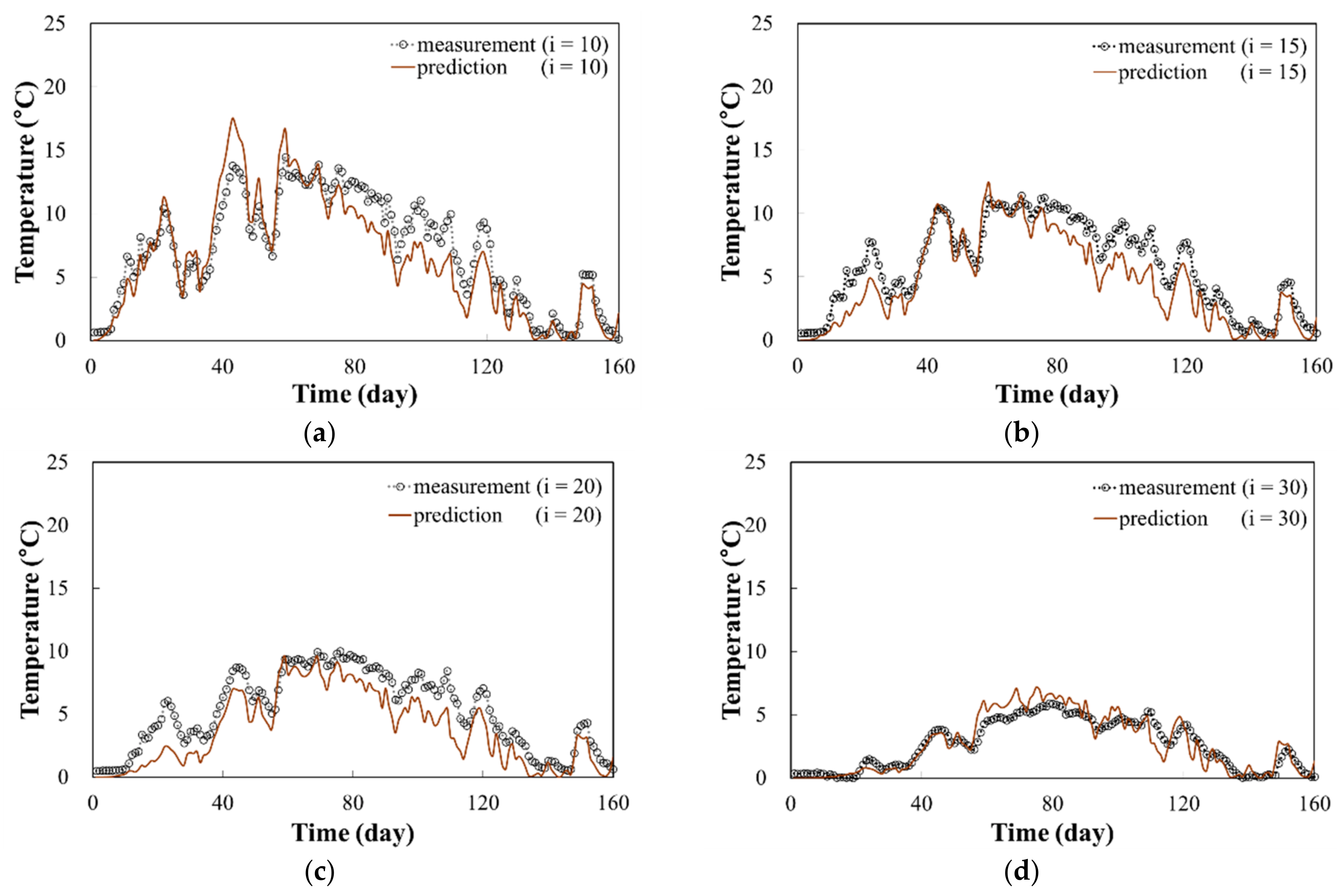
In order to verify the proposed method for lower-depth soil temperature evaluation, additional data from the other site (site C in Figure 2) were collected. The soil temperature measurements at the uppermost depth are plotted in Figure 10. Following the procedure presented in Section 5.1, the parameters A, Z, and CRCSTi,mmax were obtained (Table 3). Implementing the developed model using the values in Table 3 for different depths, we can compare the measured soil temperatures and the corresponding predicted values using Tud data (Figure 11).
The average and the maximum measured soil temperatures at the depth of 10 cm were 7.1 °C and 14.5 °C, respectively, while their predicted values were 6.6 °C and 17.5 °C, respectively. The average and the maximum measured soil temperatures (the corresponding predicted values are in parentheses) were 6.0 °C (4.7 °C) and 11.4 °C (12.4 °C), respectively, for the depth of 15 cm, 5.2 °C (3.8 °C) and 10.0 °C (9.6 °C), respectively, for the depths of 20 cm, and 2.7 °C (2.7 °C) and 5.9 °C (7.1 °C), respectively, for the depth of 30 cm. The difference in the average and the maximum soil temperatures between the measured and the predicted values ranged 0–1.4 °C and 0.4–3.0 °C, respectively. These differences in soil temperature prediction result from imperfection of soil temperature model. The developed soil temperature prediction model in this study has an advantage of simplicity associated with fewer calculations using only three fitting parameters, and reasonably predicts shallow depth soil temperatures.
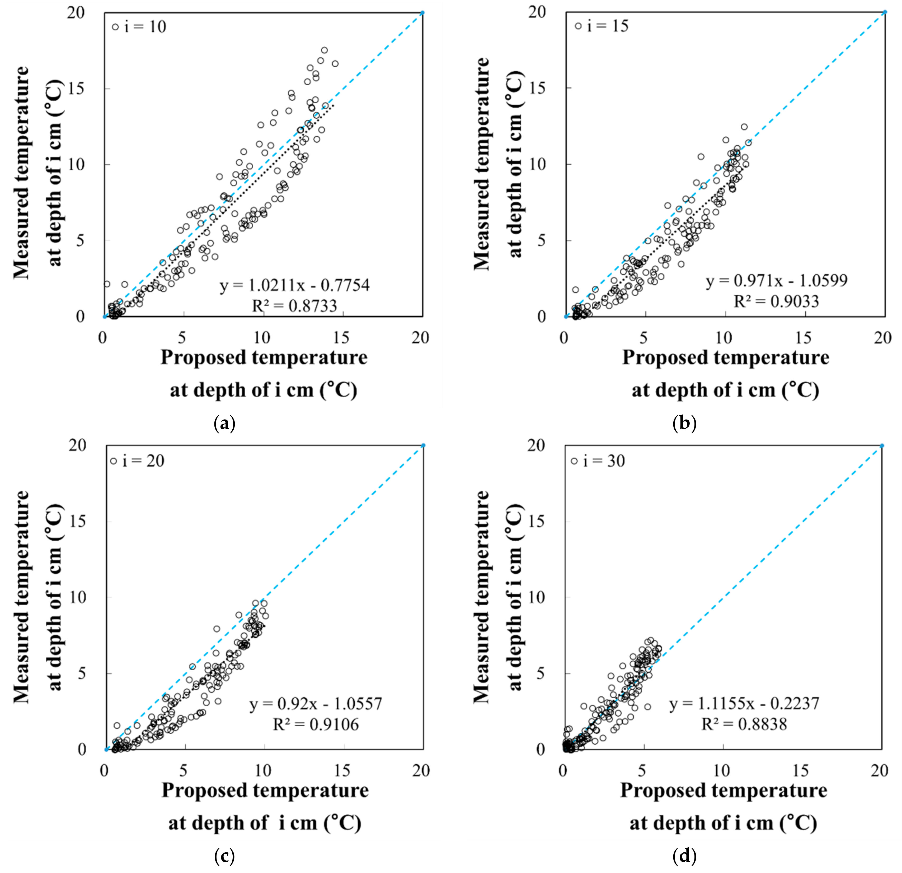
Figure 12 compares the measured and predicted soil temperatures at each depth of the site C. From the regression analysis, it can be seen that the relationship between the measured and the predicted values produced a high R2 value (ranging from 0.8733 to 0.9106). This result is an improvement of the previously proposed model [56]. From Figure 12, the soil temperature prediction at the depth of 10 cm showed the highest uncertainty, resulting in the highest scatteredness of data point and the lowest R2 value. It was noted that the uncertainty of soil temperature tends to slightly decrease as the soil temperature at the deeper depth is less influenced by the dynamic variation of air temperature.
As pointed out by Dwyer et al. [57], the advantage of using long-term data of the daily average temperature for several seasons or longer is that it reduces the deviation of prediction and the variation of temperature, which is mainly caused by climatic and ground conditions. Thus, this study used long-term lower-depth soil temperature data to develop depth profiles of soil temperature and to experimentally verify the prediction model.
Consequently, an effective and practical lower-depth soil temperature prediction model was developed. The model enables the estimation of soil temperature in various areas and strata, instead of predicting the soil temperature at one elevation. Previous studies used solar radiation, air temperature, and albedo in combination with soil characteristics (such as thermal conductivity or diffusivity) to estimate soil temperature [26,37]. However, in this study, an efficient lower-depth soil temperature estimation model was developed, in terms of the number of parameters of the model, analysis time, and the accuracy of estimation.
However, despite of simple and convenient use of the developed model for shallow-depth soil temperature prediction, there are limitations. The procedure of the mathematical model development is valid, independent of location; however, for the determination of three model fitting parameters, A, Z and CRCSTi,mmax, at least two time histories of soil temperature depth profiles are required at the target location. The three fitting parameters are functions of air temperature variation and soil characteristics (such as thermal conductivity, soil density, water content and others). Future study is recommended to quantify the effects of air temperature variation and soil characteristics on the developed soil temperature model.
The soil temperature model development requires continuous time history of soil temperature–depth profile measurement. Omission of several days of soil temperature measurements will ruin the accuracy of the proposed model. In addition, the soil temperature prediction model may induce high errors in prediction, if the spatial variability of soil characteristic (soil structure, texture, or fabric) within shallow depth (depths within 30 cm from the ground surface) is significant. However, in most of the cases, the soil’s spatial variability within shallow depth can be assumed somewhat homogeneous.

6. Conclusions

In this study, lower-depth soil temperature data were measured from late spring to early autumn (i.e., the period during which the soil temperatures within a depth range of 5–30 cm were above 0 °C) in Council, Alaska. A prediction model for lower-depth soil temperature was developed for soil layers up to 30 cm in depth. The model was intended to predict soil temperatures at a site up to 30 cm below the surface by only using the soil temperature data from the uppermost depth, which was 5 cm. The proposed model of predicting soil temperature utilized the cumulative soil temperature for the uppermost layer based on the concept of thermal response and the soil temperatures. In particular, the use of thermal response (i.e., the cumulative soil temperature), instead of using soil temperature, produced more consistent and reliable estimates of time-dependent lower-depth soil temperatures.
The mathematical relationship between CRCST*i,m and CST*ud,m was developed based on the observation results, and a procedure for predicting soil temperatures was established. The advantage of the proposed soil temperature estimation model is that it has three parameters to define and produces effective prediction results. The proposed model for evaluating the dynamic behaviors of soil temperature was verified by obtaining soil temperature data from an additional site. As evident when comparing the measured and predicted lower-depth soil temperatures, the proposed model accurately predicted soil temperatures for depths of 10, 15, 20, and 30 cm.
Consequently, the developed model could contribute to a prompt and accurate measurement of soil temperature in a permafrost active area to provide valuable information for research related to heat flux, heat energy productivity from the geothermal system, thawing of the permafrost layer, spatial variation of soil temperature, CO2 and NH4 emissions, decomposition of microbes and organic matter, and plant growth.

Author Contributions

K.P. and H.Y. conceived the study; K.P. and H.Y. performed field monitoring; K.P., H.Y., B.Y.L., and D.K. analyzed the data; K.P. and D.K. wrote the main manuscript text; and all authors approved the final manuscript.

Funding

This research was funded by the National Research Foundation of Korea Grant from the Korean Government (MSIT; the Ministry of Science and ICT) (NRF-2016M1A5A1901769; KOPRI-PN18081) (Title: Circum Arctic Permafrost Environment Change Monitoring, Future Prediction and Development Techniques of Useful Biomaterials (CAPEC Project)) and by a grant (18IFIP-B089084-05; KOPRI-PN18110) from the Industrial Facilities & Infrastructure Research Program (IFIP) from the Ministry of Land, Infrastructure and Transport, Korea.

Acknowledgments

The authors acknowledge the support by the National Research Foundation of Korea, the Ministry of Science and ICT, the Ministry of Land, Infrastructure and Transport, Korea.

Conflicts of Interest

The authors declare no conflicts of interest.

References

  1. Harrison, W.D. Permafrost response to surface temperature change and its implications for the 40,000-year surface temperature history at Prudhoe Bay, Alaska. J. Geophys. Res. 1991, 96, 683. [Google Scholar] [CrossRef]
  2. Johannessen, O.M. Satellite Evidence for an Arctic Sea Ice Cover in Transformation. Science 1999, 286, 1937–1939. [Google Scholar] [CrossRef] [PubMed]
  3. Zimov, S.A.; Schuur, E.A.G.; Chapin, F.S. Permafrost and the Global Carbon Budget. Science 2006, 312, 1612–1613. [Google Scholar] [CrossRef] [PubMed]
  4. Bhatt, U.S.; Walker, D.A.; Raynolds, M.K.; Comiso, J.C.; Epstein, H.E.; Jia, G.; Webber, P.J. Circumpolar Arctic Tundra Vegetation Change Is Linked to Sea Ice Decline. Earth Interact. 2010, 14, 1–20. [Google Scholar] [CrossRef]
  5. Screen, J.A.; Simmonds, I. The central role of diminishing sea ice in recent Arctic temperature amplification. Nature 2010, 464, 1334–1337. [Google Scholar] [CrossRef] [PubMed] [Green Version]
  6. Shim, T.; Jeong, J.; Kim, B.; Kim, S.; Kim, H. Development of Dynamical Seasonal Prediction System for Northern Winter using the Cryospheric Condition of Late Autumn. Atmosphere 2013, 23, 73–83. [Google Scholar] [CrossRef]
  7. Shim, T.; Jeong, J.; Ok, J.; Jeong, H.; Kim, B. Development and Assessment of Dynamical Seasonal Forecast System Using the Cryospheric Variables. Atmosphere 2015, 25, 155–167. [Google Scholar] [CrossRef] [Green Version]
  8. Pachauri, R.K.; Reisinger, A. Climate Change 2007: Synthesis Report. Contribution of Working Groups I, II and III to the Fourth Assessment Report of the Intergovernmental Panel on Climate Change; Intergovernmental Panel on Climate Change (IPCC): Geneva, Switzerland, 2007. [Google Scholar]
  9. Roffey, R. Climate Change and Natural Disasters: A Challenge for Russian Policy-Makers; FOI-R-3874; FOI: Stockholm, Sweden, 2014; ISSN 16501942. [Google Scholar]
  10. Harris, C.; Davies, M.C.; Etzelmüller, B. The assessment of potential geotechnical hazards associated with mountain permafrost in a warming global climate. Permafr. Periglac. Process. 2001, 12, 145–156. [Google Scholar] [CrossRef]
  11. Pachauri, R.K.; Meyer, L.A. Climate change 2014: Synthesis Report. Contribution of Working Groups I, II and III to the Fifth Assessment Report of the Intergovernmental Panel on Climate Change; Intergovernmental Panel on Climate Change (IPCC): Geneva, Switzerland, 2014. [Google Scholar]
  12. Qian, B.; Gregorich, E.G.; Gameda, S.; Hopkins, D.W.; Wang, X.L. Observed soil temperature trends associated with climate change in Canada. J. Geophys. Res. 2011, 116. [Google Scholar] [CrossRef]
  13. Lund, M.; Hansen, B.U.; Pedersen, S.H.; Stiegler, C.; Tamstorf, M.P. Characteristics of summer-time energy exchange in a high Arctic tundra heath 2000–2010. Tellus B: Chem. Phys. Meteorol 2014, 66, 21631. [Google Scholar] [CrossRef] [Green Version]
  14. Nezhad Gashti, E.H. Thermo-Mechanical Behaviour of Ground-Source Thermo-Active Structures. Ph.D. Thesis, University of Oulu, Oulu, Finland, 2016. [Google Scholar]
  15. Kurylyk, B.L.; Hayashi, M.; Quinton, W.L.; Mckenzie, J.M.; Voss, C.I. Influence of vertical and lateral heat transfer on permafrost thaw, peatland landscape transition, and groundwater flow. Water Resour. Res. 2016, 52, 1286–1305. [Google Scholar] [CrossRef]
  16. Stoller, E.W.; Wax, L.M. Periodicity of Germination and Emergence of Some Annual Weeds. Weed Sci. 1973, 21, 574–580. [Google Scholar]
  17. Parton, W.J. Predicting soil temperatures in a shortgrass steppe. Soil Sci. 1984, 138, 93–101. [Google Scholar] [CrossRef]
  18. Koerselman, W.; Kerkhoven, M.B.; Verhoeven, J.T. Release of inorganic N, P and K in peat soils; effect of temperature, water chemistry and water level. Biogeochemistry 1993, 20, 63–81. [Google Scholar] [CrossRef]
  19. Giardina, C.P.; Ryan, M.G. Evidence that decomposition rates of organic carbon in mineral soil do not vary with temperature. Nature 2000, 404, 858–861. [Google Scholar] [CrossRef] [PubMed]
  20. Jackson, T.; Mansfield, K.; Saafi, M.; Colman, T.; Romine, P. Measuring soil temperature and moisture using wireless MEMS sensors. Measurement 2008, 41, 381–390. [Google Scholar] [CrossRef]
  21. Fröb, K. Measuring and Modeling of Soil Thermal Properties and Ground Heat Flux at Two Different Sites at Lena Delta. Ph.D. Thesis, University of Leipzig, Leipzig, Germany, 2011. [Google Scholar]
  22. Holmes, T.R.; Owe, M.; Jeu, R.A.; Kooi, H. Estimating the soil temperature profile from a single depth observation: A simple empirical heatflow solution. Water Resour. Res. 2008, 44. [Google Scholar] [CrossRef]
  23. Zhang, T.; Barry, R.G.; Gilichinsky, D. An amplified signal of climatic change in soil temperatures during the last century at Irkutsk, Russia. Clim. Chang. 2001, 49, 41–76. [Google Scholar] [CrossRef]
  24. Niu, G.Y.; Sun, S.F.; Hong, Z.X. Numerical simulation on water and heat transport in the desert soil and atmospheric boundary layer. Acta Meteorol. Sin. 1997, 55, 398–405. [Google Scholar]
  25. Dakshanamurthy, V.; Fredlund, D.G. A mathematical model for predicting moisture flow in an unsaturated soil under hydraulic and temperature gradients. Water Resour. Res. 1981, 17, 714–722. [Google Scholar] [CrossRef]
  26. Mahrer, Y.; Katan, J. Spatial Soil Temperature Regime Under Transparent Polyethylene Mulch. Soil Sci. 1981, 131, 82–87. [Google Scholar] [CrossRef]
  27. Tabbagh, A.; Bendjoudi, H.; Benderitter, Y. Determination of recharge in unsaturated soils using temperature monitoring. Water Resour. Res. 1999, 35, 2439–2446. [Google Scholar] [CrossRef] [Green Version]
  28. Rajver, D.; Šafanda, J.; Shen, P. The climate record inverted from borehole temperatures in Slovenia. Tectonophysics 1998, 291, 263–276. [Google Scholar] [CrossRef]
  29. Pollack, H.N.; Demezhko, D.Y.; Duchkov, A.D.; Golovanova, I.V.; Huang, S.; Shchapov, V.A.; Smerdon, J.E. Surface temperature trends in Russia over the past five centuries reconstructed from borehole temperatures. J. Geophys. Res. Solid Earth 2003, 108. [Google Scholar] [CrossRef]
  30. Huang, S.; Pollack, H.N.; Shen, P. Temperature trends over the past five centuries reconstructed from borehole temperatures. Nature 2000, 403, 756–758. [Google Scholar] [CrossRef] [PubMed]
  31. Hu, Q.; Feng, S. A Daily Soil Temperature Dataset and Soil Temperature Climatology of the Contiguous United States. J. Appl. Meteorol. 2003, 42, 1139–1156. [Google Scholar] [CrossRef] [Green Version]
  32. Bendjoudi, H.; Cheviron, B.; Guérin, R.; Tabbagh, A. Determination of upward/downward groundwater fluxes using transient variations of soil profile temperature: Test of the method with Voyons (Aube, France) experimental data. Hydrol. Process. 2005, 19, 3735–3745. [Google Scholar] [CrossRef]
  33. Gao, Z. Determination of soil heat flux in a Tibetan short-grass prairie. Bound. Layer Meteorol. 2005, 114, 165–178. [Google Scholar] [CrossRef]
  34. Gao, Z.; Fan, X.; Bian, L. An analytical solution to one-dimensional thermal conduction-convection in soil. Soil Sci. 2003, 168, 99–107. [Google Scholar] [CrossRef]
  35. Gao, Z.; Lenschow, D.H.; Horton, R.; Zhou, M.; Wang, L.; Wen, J. Comparison of two soil temperature algorithms for a bare ground site on the Loess Plateau in China. J. Geophys. Res. 2008, 113. [Google Scholar] [CrossRef]
  36. Liang, L.L.; Riveros-Iregui, D.A.; Emanuel, R.E.; Mcglynn, B.L. A simple framework to estimate distributed soil temperature from discrete air temperature measurements in data-scarce regions. J. Geophys. Res. Atmos. 2014, 119, 407–417. [Google Scholar] [CrossRef] [Green Version]
  37. Lei, S.; Daniels, J.L.; Bian, Z.; Wainaina, N. Improved soil temperature modeling. Environ. Earth Sci. 2010, 62, 1123–1130. [Google Scholar] [CrossRef]
  38. Sayde, C.; Buelga, J.B.; Rodriguez-Sinobas, L.; Khoury, L.E.; English, M.; Giesen, N.V.; Selker, J.S. Mapping variability of soil water content and flux across 1–1000 m scales using the Actively Heated Fiber Optic method. Water Resour. Res. 2014, 50, 7302–7317. [Google Scholar] [CrossRef]
  39. Benítez-Buelga, J.; Rodríguez-Sinobas, L.; Calvo, R.S.; Gil-Rodríguez, M.; Sayde, C.; Selker, J.S. Calibration of soil moisture sensing with subsurface heated fiber optics using numerical simulation. Water Resour. Res. 2016, 52, 2985–2995. [Google Scholar] [CrossRef]
  40. Prasad, V.V.V.; Craufurd, P.Q.; Kakani, V.G.; Wheeler, T.R.; Boote, K.J. Influence of high temperature during pre- and post-anthesis stages of floral development on fruit-set and pollen germination in peanut. Funct. Plant Biol. 2001, 28, 233–240. [Google Scholar] [CrossRef]
  41. Frauenfeld, O.W.; Zhang, T.; Mccreight, J.L. Northern Hemisphere freezing/thawing index variations over the twentieth century. Int. J. Climatol. 2006, 27, 47–63. [Google Scholar] [CrossRef] [Green Version]
  42. Isaksen, K.; Benestad, R.E.; Harris, C.; Sollid, J.L. Recent extreme near-surface permafrost temperatures on Svalbard in relation to future climate scenarios. Geophys. Res. Lett. 2007, 34. [Google Scholar] [CrossRef]
  43. Schuh, C.; Frampton, A.; Christiansen, H.H. Soil moisture redistribution and its effect on inter-annual active layer temperature and thickness variations in a dry loess terrace in Adventdalen, Svalbard. Cryosphere Discuss. 2017, 11, 635–651. [Google Scholar] [CrossRef]
  44. Casasso, A.; Sethi, R. Efficiency of closed loop geothermal heat pumps: A sensitivity analysis. Renew. Energy 2014, 62, 737–746. [Google Scholar] [CrossRef] [Green Version]
  45. Emberlin, J.; Mullins, J.; Corden, J.; Millington, W.; Brooke, M.; Savage, M.; Jones, S. The trend to earlier birch pollen seasons in the U.K.: A biotic response to changes in weather conditions? Grana 1997, 36, 29–33. [Google Scholar] [CrossRef] [Green Version]
  46. Plattner, G.K.; Stocker, P.; Midgley, P.; Tignor, M. IPCC Expert Meeting on the Science of Alternative Metrics: Meeting Report; UNT Libraries: The Grand Hotel, Oslo, Norway, 2009. [Google Scholar]
  47. Kirschbaum, M.U. Climate-change impact potentials as an alternative to global warming potentials. Environ. Res. Lett. 2014, 9, 034014. [Google Scholar] [CrossRef] [Green Version]
  48. Kim, H.M.; Jung, J.Y.; Yergeau, E.; Hwang, C.Y.; Hinzman, L.; Nam, S.; Lee, Y.K. Bacterial community structure and soil properties of a subarctic tundra soil in Council, Alaska. FEMS Microbiol. Ecol. 2014, 89, 465–475. [Google Scholar] [CrossRef] [PubMed] [Green Version]
  49. Kim, H.M.; Lee, M.J.; Jung, J.Y.; Hwang, C.Y.; Kim, M.; Ro, H.; Lee, Y.K. Vertical distribution of bacterial community is associated with the degree of soil organic matter decomposition in the active layer of moist acidic tundra. J. Microbiol. 2016, 54, 713–723. [Google Scholar] [CrossRef] [PubMed]
  50. Ahmad, M.F.; Rasul, D.G. Prediction of Soil Temperature by Air Temperature: A Case Study for Faisalabad. Pak. J. Meteorol. 2008, 5, 19–27. [Google Scholar]
  51. Barman, D.; Kundu, D.; Pal, S.; Pal, S.; Chakraborty, A.; Jha, A.; Bhattacharyya, P. Soil temperature prediction from air temperature for alluvial soils in lower Indo-Gangetic plain. Int. Agrophys. 2017, 31, 9–22. [Google Scholar] [CrossRef] [Green Version]
  52. Dyrness, C. Control of Depth to Permafrost and Soil Temperature by the Forest Floor in Black Spruce/Feathermoss Communities. United States Department of Agriculture: Washington, DC, USA, 1982. [Google Scholar] [CrossRef]
  53. Quinton, W.L.; Pomeroy, J.W. Transformations of runoff chemistry in the Arctic tundra, Northwest Territories, Canada. Hydrol. Process. 2006, 20, 2901–2919. [Google Scholar] [CrossRef] [Green Version]
  54. Qian, C. Evaluation of the Energy-Based Runoff Concept for A Subalpine Tundra Hillslope. Ph.D. Thesis, University of Waterloo, Waterloo, ON, Canada, 2012. [Google Scholar]
  55. Weibull, W. A Statistical Distribution Function of Wide Applicability. J. Appl. Mech. 1951, 18, 293–297. [Google Scholar]
  56. Hu, G.; Wu, X.; Zhao, L.; Li, R.; Wu, T.; Xie, C.; Cheng, G. An improved model for soil surface temperature from air temperature in permafrost regions of Qinghai-Xizang (Tibet) Plateau of China. Meteorol. Atmos. Phys. 2016, 129, 441–451. [Google Scholar] [CrossRef]
  57. Dwyer, L.M.; Hayhoe, H.N.; Culley, J.L. Prediction of soil temperature from air temperature for estimating corn emergence. Can. J. Plant. Sci. 1990, 70, 619–628. [Google Scholar] [CrossRef]
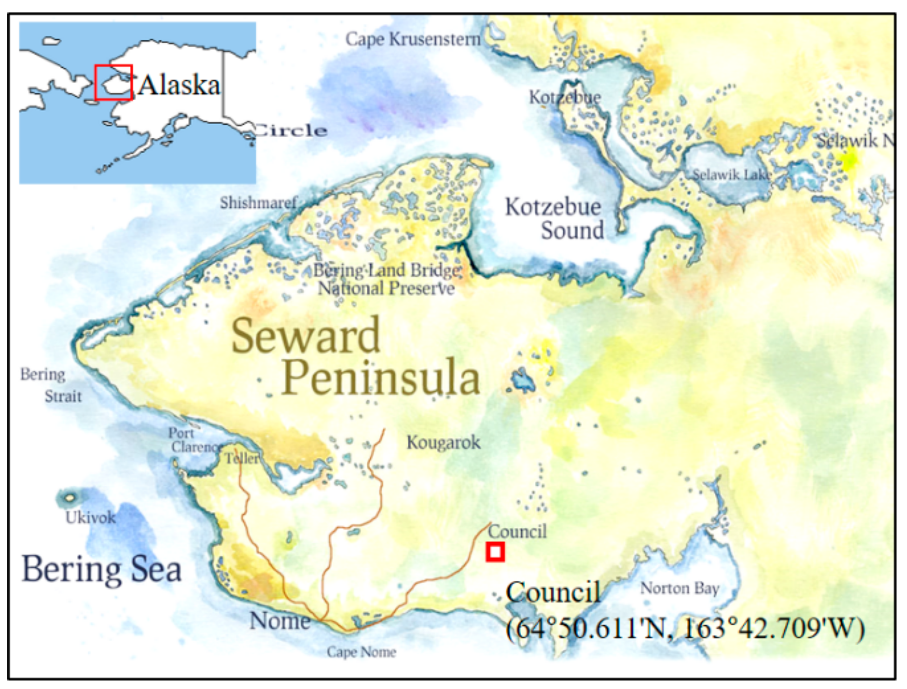
Figure 1. Measurement site in Council, the Seward Peninsula, Alaska.
Applsci 08 01886 g001
Figure 2. Locations of the soil temperature measurement sensors of the test sites.
Applsci 08 01886 g002
Figure 3. Temperature measurements of (a) air temperature above 1.2 m from the ground surface; and soil temperatures at the (b) site A and (c) site B.
Applsci 08 01886 g003
Figure 4. Measured soil temperatures at different depths at the sites A and B: depths of (a) 5 cm; (b) 10 cm; (c) 15 cm; (d) 20 cm; and (e) 30 cm.
Applsci 08 01886 g004
Figure 5. Relationships between soil temperature at a depth of 5 cm and those observed at depths of 10, 15, 20, and 30 cm in the (a) site A and (b) site B.
Applsci 08 01886 g005
Figure 6. CRCSTi,m and CSTud,m curves for the (a) site A and (b) site B.
Applsci 08 01886 g006
Figure 7. CRCST*i,m and CST*ud,m curves for the (a) site A and (b) site B.
Applsci 08 01886 g007
Figure 8. Correlations between fitting parameters (A and Z) and depth (Di). (a) Relationship between A/Di and Di; and (b) relationship between ZDi and Di.
Applsci 08 01886 g008
Figure 9. Correlations between the maximum values of cumulative soil temperature (CRCSTi,mmax/Di) normalized by depth and depth Di.
Applsci 08 01886 g009
Figure 10. Daily average soil temperature at the uppermost depth in the site C.
Applsci 08 01886 g010
Figure 11. Measured and predicted temperature curves for additional data at depths of (a) 10 cm; (b) 15 cm; (c) 20 cm; and (d) 30 cm.
Applsci 08 01886 g011
Figure 12. Regression analysis for measured and predicted temperature curves for additional data at depths of (a) 10 cm; (b) 15 cm; (c) 20 cm; and (d) 30 cm.
Applsci 08 01886 g012
Table 1. Values of fitting parameters A and Z.
Depth (cm)Test SiteFitting Parameter AFitting Parameter ZA/DiZDi
10A3.9261.4440.39314.437
B3.7291.4320.37314.317
15A3.9701.5680.26523.522
B3.8361.6380.25624.569
20A3.9421.7050.19734.099
B3.8981.9560.19539.120
30A3.9822.0430.13361.280
B4.0572.8420.13585.266
Table 2. Values of fitting parameters A and Z.
Depth (cm)Test SiteCRCSTi,mmaxCRCSTi,mmax/Di
10A483.348.3
B606.060.6
15A399.426.6
B515.234.3
20A312.115.6
B389.419.5
30A180.36.0
B207.56.9
Table 3. Values of the fitting parameters A and Z and CRCSTi,mmax for the site C.
Depth (cm)Fitting Parameter AFitting Parameter ZCRCSTi,mmax
103.84521.3804621.259
153.88121.1687407.675
203.90701.9046302.345
303.94362.2992198.401