Article

Relay Selection Scheme for Multi-Hop Transmission of MU-MIMO System

Department of Information and Communication Engineering, Sejong University, Gunja-dong 98, Gwangjin-gu, Seoul 04998, Korea
*
Author to whom correspondence should be addressed.
Appl. Sci. 2018, 8(10), 1747; https://doi.org/10.3390/app8101747
Submission received: 7 August 2018 / Revised: 13 September 2018 / Accepted: 25 September 2018 / Published: 27 September 2018

Abstract

:
Recently, wireless communication systems use a multi-hop transmission scheme using a relay to expand the cell coverage of the system. The multi-hop transmission scheme can expand the cell coverage of wireless communication systems. However, if an appropriate relay is not selected, errors generated during signal processing in the relay are transmitted to the receiver. Therefore, a relay selection scheme is essential for reliable multi-hop transmission. This paper proposes a relay selection scheme for reliable multi-hop transmission in a multi user-multiple input multiple output (MU-MIMO) system. The proposed relay selection scheme uses a MIMO channel matrix between the transmitter and relays to select an appropriate relay. The proposed relay selection scheme obtains the singular values of the MIMO channel matrix using the singular value decomposition (SVD). Then, the sum of the singular values is calculated, and the relay having the largest value is selected. Therefore, in the proposed relay selection scheme, although the transmitter only knows the channel information between the transmitter and relays, the transmitter can select an appropriate relay for reliable multi-hop transmission.

1. Introduction

Recently, the multi user-multiple input multiple output (MU-MIMO) scheme plays an important role in increasing the average throughput of the cell and the throughput of the cell edge user in the long term evolution-advanced (LTE-A) [1]. The MU-MIMO scheme can increase the channel capacity without additional bandwidth allocation by transmitting signals to multiple user equipment (UEs) at the same time [2,3]. In addition, since one base station (BS) simultaneously transmits signal to multiple UEs, the cell average throughput of the LTE-A communication system can be increased [4]. There are many MU-MIMO schemes. Typical MU-MIMO schemes include channel inversion scheme and block diagonalization (BD) scheme. In the channel inversion scheme, the BS multiplies the transmission signal by the inverse matrix of the MIMO channel matrix between the BS and UE. Therefore, when the BS transmits the pre-coded signal, the UE receives the desired signal in which the interference signal is removed and only the noise is added. In the BD scheme, a pre-coding matrix is generated using the MIMO channel matrix between the BS and UE, and the BS transmits the signal multiplied by the pre-coding matrix. When the UE receives the pre-coding signal of the BD scheme, the UE receives the desired signal with the interference cancellation and only the noise is added, similar to the channel inversion scheme. Therefore, the MU-MIMO scheme is essential for increasing the cell average throughput of the LTE-A communication system. The sum capacity of the MU-MIMO channel is proved to be achieved by the dirty paper coding (DPC) which perfectly pre-subtracts the inter user interference (IUI). However, the DPC is difficult to apply to MU-MIMO system in practice, since the DPC requires additional complexity at the BS and UE. The BD scheme has been proposed to solve the high implementation complexity and nonlinear characteristic of DPC. Unlike the DPC, the BD scheme is a linear precoding scheme and its implementation complexity is very low. In addition, when there is no IUI, it is possible to approximately achieve the sum capacity that can be achieved by the DPC [5]. Therefore, this paper adopts the BD scheme with low implementation complexity.
In order to obtain an appropriate performance evaluation of MIMO schemes, the usage of wireless channel model reflecting spatial channel characteristic is required [6,7]. Therefore, the 3rd generation partnership project (3GPP) proposed a 3-dimensional (3D) channel model through TR36.873 document. The 3D channel model proposed by 3GPP has additional parameters unlike the conventional 2-dimensional (2D) channel model. The large-scale parameters of the 3D channel model are shadow fading, delay spread, and angular spread. The small-scale parameters include delays, cluster power, angle-of-arrival (AOA), and angle-of-departure (AOD) [8]. Among these parameters, the AOA can be used to estimate the localization of the UEs. There is a study related to AOA-based localization estimation using MIMO-OFDM channel state information (CSI) [9]. In addition, the 3D channel model includes parameters related to polarization and antenna configuration (linear antenna, array antenna) [10]. The proposed relay selection scheme can select appropriate relay in 3D channel as well as 2D channel.
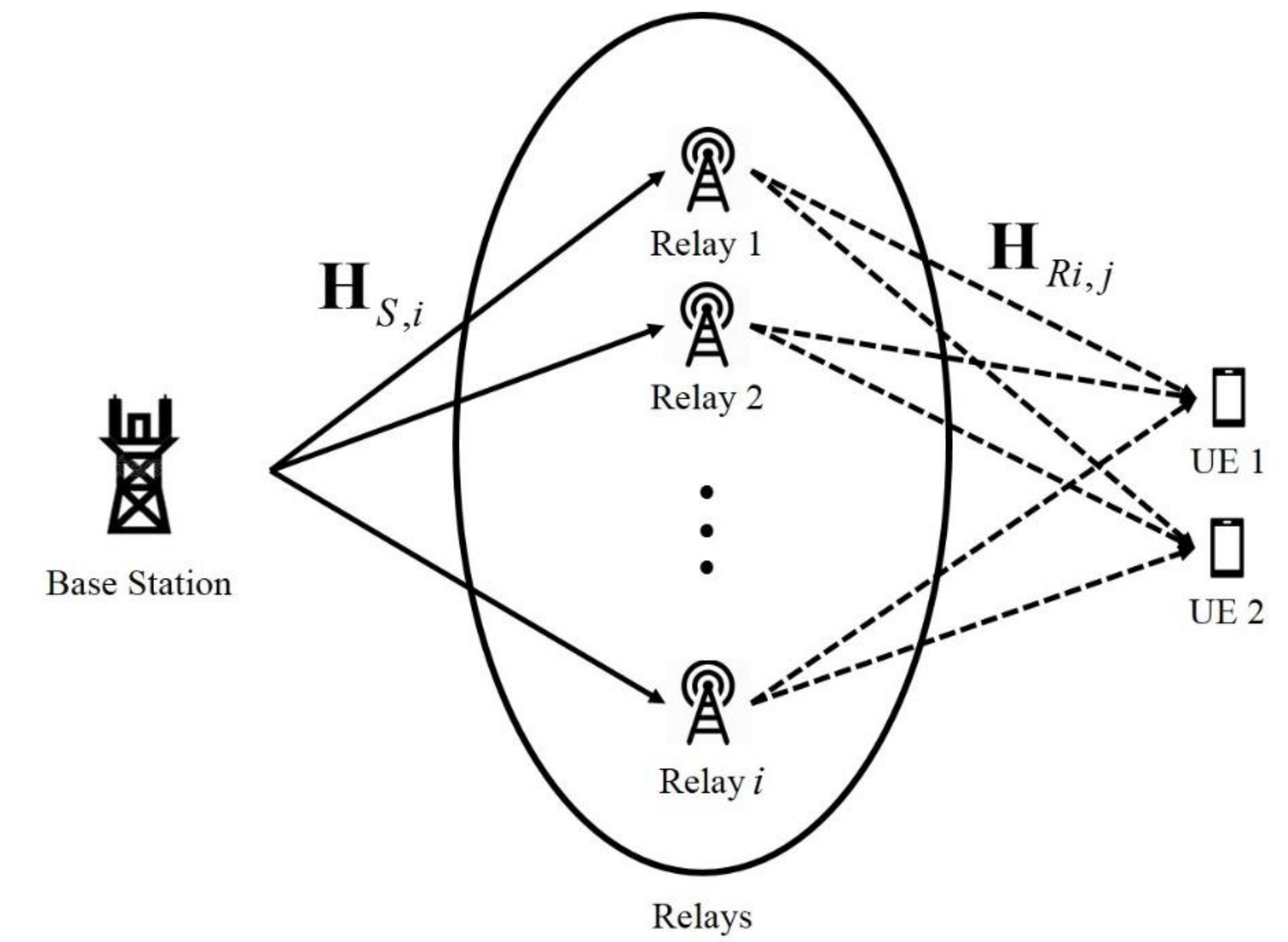
The cell coverage is very important in wireless communication system such as LTE or LTE-A. As the distance between the BS and UE increases, the power of the transmitted signal is attenuated by the path loss. Thereby the received signal-to-noise ratio (SNR) is reduced. The reduction of the SNR of the received signal degrades the reliability of wireless communication systems such as the LTE or LTE-A. The multi-hop transmission system can overcome the above problem. The multi-hop transmission system can mitigate the power attenuation of the transmitted signal due to the path loss by using the relay between the BS and UE. As a result, the cell coverage of the wireless communication system can be expanded. There are amplify-and-forward (AF) relaying scheme and decode-and-forward (DF) relaying scheme in the typical multi-hop transmission schemes [11]. In the AF relaying scheme, the relay receives a signal from the BS, and then amplifies the received signal, and transmits the amplified signal to the UE. Therefore, the signal processing in the relay is simple, but the noise is also amplified when the signal is amplified. In the DF relaying scheme, the relay receives a signal from the BS, and then the relay performs a decoding and detection. Then, the relay re-modulates the signal and forwards it to the UE. Therefore, the signal processing in the relay is complicated, but the noise is not amplified because the signal is not amplified [12]. The proposed relay selection scheme adapts the DF relaying scheme. However, the DF relaying scheme has the error propagation problem that the error generated in a signal processing in the relay is transmitted to the UE [13]. Therefore, the relay selection scheme is essential to mitigate the error propagation problem.
In the multi-hop transmission system, the relay selection scheme is essential. If an appropriate relay is not selected, the SNR of the received signal is reduced due to the effect of the error propagation problem. Therefore, the relay selection scheme is very important in a multi-hop transmission system using a relay [14,15]. There are many difficult relay selection schemes. Typical relay selection schemes include the random relay selection scheme, threshold-based relay selection scheme and best harmonic mean (BHM) scheme [16]. The random relay selection scheme randomly selects one relay among several relays. In other words, the random relay selection scheme selects a relay without considering the SNR of the received signal and channel condition. Therefore, the random relay selection scheme is very simple, but it is possible to select a relay having a bad channel condition. It degrades the performance of the multi-hop transmission system. Then, one relay is randomly selected among the relay candidates. The BHM scheme is the optimal relay selection scheme. In the BHM scheme, a harmonic mean of the channel amplitude between the BS and relays and the channel amplitude between the relays and UE is obtained, and then the relay having the largest value is selected [15]. Since the BHM scheme is an optimal relay selection scheme, it provides very high reliability, but it is very difficult to apply it to the actual system because the BS needs to know all channel information. The proposed relay selection scheme selects a relay using only the channel information between the BS and relays, which have the greatest influence on error propagation. Therefore, the proposed relay selection scheme can be applied to the actual system more easily than the BHM scheme because it only uses the channel information between the BS and relays.
This paper is organized as follows. Section 2 shows the system model of the proposed relay selection scheme. Section 3 explains the conventional relay selection schemes. Section 4 describes the proposed relay selection scheme. Section 5 shows the simulation results by comparing the conventional and proposed relay selection scheme. Finally, Section 6 presents our conclusion.

2. System Model

2.1. System Model

This section describes the system model of this paper. This paper proposes the relay selection scheme for multi-hop transmission system of MU-MIMO. Figure 1 shows the multi-hop transmission system model of MU-MIMO.
In the MU-MIMO multi-hop transmission system, the BS transmits a signal to the relay through the MIMO channel. The relay multiplies the received signal from the BS by the pre-coding matrix and transmits the signal to UEs. In Figure 1, H S , i means the MIMO channel matrix between the BS and relays, and H R i , j refers to the channel matrix between the relays and UEs. In the above channel matrix, the i denotes the index of the relays, and j refers to the index of the UEs. When the number of transmit/receive antennas of the BS is N t , the relay is N r , and UE is N U E , the H S , i is H S , i N r × N t , H R i , j is H R i , j N U E × N r .

2.2. Decode-and-Forward (DF) Relaying Scheme

The DF relaying scheme is one of the multi-hop transmission schemes. Figure 2 shows the model of the DF relaying scheme.
In the DF relaying scheme, the BS transmits the signal to be transmitted to the UEs to the relay. The relay decodes and detects the received signal from the BS. Then the relay re-modulates the signal and transmits it to the UEs. Therefore, the DF relaying scheme has a complicated signal processing in the relay, but does not amplify the noise and does not require a complex power allocation scheme. However, the DF relaying scheme has the error propagation problem because it uses the relay. Therefore, the DF relaying scheme requires the appropriate relay selection scheme to overcome the error propagation problem.

2.3. Block Diagonalization (BD) Scheme

The MU-MIMO scheme can increase the channel capacity and throughput without additional bandwidth allocation by simultaneously transmitting signals to multiple UEs. Therefore, the MU-MIMO scheme plays an important role in increasing the cell average throughput and cell edge user throughput of the LTE-A communication system. Figure 3 shows the system model of the MU-MIMO scheme.
In the MU-MIMO scheme, the BS transmits the signal multiplied by the pre-coding matrix so that the UEs can distinguish their signal even if the BS transmits signals to multiple UEs at the same time. The block diagonalization (BD) scheme is a typical MU-MIMO pre-coding scheme. In the BD scheme-based MU-MIMO system, the received signal of the j-th UE is as follows:
y j = H S , U E   j W j x j + k = 1 ,   k j K H S , U E   j W k x k + N j ,  
where the K denotes the total number of UEs, and the j refers to the index of the UE. H S , U E   j N R × N S means the MIMO channel matrix between the BS and the j-th UE and the W j N s × N R denotes the pre-coding matrix of the j-th UE. x j N R × 1 refers to the transmitted signal to the j-th UE, and N j is the additive white Gaussian noise (AWGN). In Equation (1), H S , U E   j W k is the interference to the j-th UE. Therefore, the H S , U E   j W k must satisfy the following condition. The condition is as follows:
H S , U E   j W k = 0 N R × N S ,         j k .  
In order to satisfy the total transmission power constraint, the pre-coding matrix W j must be unitary. If the condition of Equation (2) is satisfied, the received signal of the j-th UE is as follows:
y j = H S , U E   j W j x j + N j .  
In order to generate the pre-coding matrix satisfying the condition of the Equation (2), H ˜ S , U E   j is defined as follows:
H ˜ S , U E   j = [ ( H S , U E   1 ) H ( H S , U E   j 1 ) H   ( H S , U E   j + 1 ) H ( H S , U E   K ) H ] ,  
where the H ˜ S , U E   j is defined as a channel matrix of all UEs excluding the channel matrix of the j-th UE, and the singular value decomposition (SVD) of the H ˜ S , U E   j is as follows:
H ˜ S , U E   j = U ˜ j ˜ j [ V ˜ j n o n z e r o       V ˜ j z e r o ] H ,  
where the V ˜ j n o n z e r o and V ˜ j z e r o are composed of right vectors that correspond to non-zero singular values and zero singular values, respectively. The V ˜ j z e r o becomes a null space orthogonal basis matrix of the H ˜ S , U E   j . The H ˜ S , U E   j V ˜ j z e r o is as follows:
H ˜ S , U E   j V ˜ j z e r o = U ˜ j [ ˜ j n o n z e r o       0 ] [ ( V ˜ j n o n z e r o ) H           ( V ˜ j z e r o ) H ] V ˜ j z e r o                                               = U ˜ j ˜ j n o n z e r o ( V ˜ j n o n z e r o ) H V ˜ j z e r o = U ˜ j ˜ j n o n z e r o 0                                               = 0 .
From Equation (6), it can be seen that V ˜ j z e r o is in the null space of H ˜ S , U E   j , that is, when a signal is transmitted in the direction of V ˜ j z e r o , all but the j-th UE receives no signal at all. In order to satisfy the condition shown in the Equation (2), W j = V ˜ j z e r o must be satisfied. Thus, W j = V ˜ j z e r o can be used for pre-coding matrix the j-th UE signal.

3. Conventional Relay Selection Scheme

This section describes the conventional relay selection schemes. In the multi-hop transmission system, the relay selection scheme is essential. Especially, the relay selection scheme is very important in the DF scheme based multi-hop transmission system. If an appropriate relay is not selected, the error propagation problem can degrade the wireless communication reliability of the multi-hop transmission system. An alternative solution to the error propagation problem is to use more power at the base station. This alternative solution can increase the received SNR at the relay and reduce detection or decoding error. However, this method is very limited in cost because it requires an expensive amplifier. Therefore, the relay selection scheme is very important in the many studies related to the relay selection scheme.

3.1. Random Relay Selection Scheme

One of the typical relay selection schemes is the random relay selection scheme. The random relay selection scheme randomly selects the relay without considering factors such as the channel condition and SNR of the received signal. Therefore, the random relay selection scheme is very simple, and the relay for multi-hop transmission can be selected quickly. However, since the relay is randomly selected, the appropriate relay may not be selected. Since the relay having a bad channel condition can be selected, the error propagation problem is caused. In order to select the relay with good channel condition, other relay selection schemes have been studied in consideration of factors such as the channel condition and SNR of the received signal.

3.2. Best Harmonic Mean (BHM) Relay Selection Scheme

The best harmonic mean (BHM) relay selection scheme is a method for the selection of the optimal relay. The BHM relay selection scheme uses the harmonic mean of the channel amplitude between the BS and relays and channel amplitude between the relays and UEs. The harmonic mean of the two channel amplitudes is as follows:
h B H M = 1 ( | H S , i | 2 + | H R i , j | 2 ) ,  
where the H S , i denotes the channel between the BS and relays, and the H R i , j refers to the channel between the relays and UEs. The |         | refers to the 2-norm (amplitude) of the channel matrix. The BS selects the relay with largest harmonic mean of the two channel amplitudes. Therefore, the BHM relay selection scheme can select the optimal relay. However, in the BHM relay selection scheme, the BS must know all channel information. Therefore, the BHM relay selection scheme is very complicated compared to other relay selection schemes, thus it is difficult to apply the scheme to the actual multi-hop transmission system.

4. Proposed Relay Selection Scheme

4.1. Singular Value Decomposition (SVD)-Based Relay Selection in 2-Dimensional (2D) Channel Model

This section describes the proposed relay selection scheme in the conventional 2-dimensional (2D) channel environment. Unlike the conventional relay selection schemes, the proposed relay selection scheme uses only the channel information between the BS and relays. When the channel matrix between the BS and relays is H S , i N r × N t , the singular value decomposition (SVD) of H S , i is as follows:
H S , i = U i i V i H ,           U i N r × N r ,       i N r × N t ,       V i N t × N t ,  
where the U i and V i are orthogonal matrices and the main diagonal entries of the i are the singular values of the H S , i and other entries are zero. In the proposed relay selection scheme, the BS calculates the following equation for each relay to select the appropriate relay,
t r , i = tr ( i ) = k = 1 N t σ i , k ,  
where the σ i , k is the singular value of the H S , i . In other words, the BS calculates the sum of the singular value of the channel matrix between the BS and relays. Then, the relay having the largest value of Equation (9) is selected. As a result, the proposed relay selection scheme can select an appropriate relay using only the channel information between the BS and relays. After the relay is selected, the BS transmits the signal to be transmitted to the UEs through the MIMO channel between the BS and selected relay. The received signal of the selected relay is as follows:
y R = H S , R x S + N R .  
The selected relay detects the signal using the zero forcing (ZF) detection scheme [17]. The filter matrix used in the ZF detection scheme is as follows:
G R = ( H S , R H · H S , R ) 1 · H S , R H .  
The relay detects the signal by multiplying the received signal by the filter matrix G R [17]. The detected signal at the relay is as follows:
x ^ R = G R y R = ( H S , R H · H S , R ) 1 · H S , R H · ( H S , R x S + N R ) = ( H S , R H · H S , R ) 1 · ( H S , R H · H S , R ) x S + G R N R           = x S + G R N R .
Equation (12) represents the process in which the selected relay through the proposed relay selection scheme detects the signal transmitted from the base station through the filter matrix of the ZF detection scheme.
When the selected relay transmits the signal to UEs, it transmits the signal by applying the BD-based MU-MIMO pre-coding to cancel inter-user interference. As described in Section 2.3, when the relay transmits the signal with a pre-coding matrix applied, the received signal of the j-th UE is as follows:
y U E , j = H R , U E   j W j x ^ R , U E   j + N j ,  
where the W j denotes the pre-coding matrix of the j-th UE. The j-th UE detects the received signal using the ZF detection scheme. The filter matrix used in the j-th UE to detect the signal is as follows:
G U E , j = ( [ H R , U E   j W j ] H [ H R , U E   j W j ] ) 1 [ H R , U E   j W j ] H .  
The j-th UE detects the signal by multiplying the received signal by the filter matrix G U E , j . The detected signal at the j-th UE is as follows:
x ^ U E , j = G U E , j y U E , j = ( [ H R , U E   j W j ] H [ H R , U E   j W j ] ) 1 [ H R , U E   j W j ] H ( H R , U E   j W j x ^ R , U E   j + N j )                     = ( [ H R , U E   j W j ] H [ H R , U E   j W j ] ) 1 ( [ H R , U E   j W j ] H [ H R , U E   j W j ] ) x ^ R , U E   j + G U E , j N j                     = x ^ R , U E   j + G U E , j N j .
The proposed relay selection scheme uses the singular values of the channel matrix between the BS and relays. After calculating the SVD of the channel matrix between the BS and relays, the singular values are obtained from the matrix having the singular values. Then, the sum of the singular values is obtained, and the relay having the largest value is selected. As a result, the proposed relay selection scheme provides the method of selecting the appropriate relay in the MU-MIMO multi-hop transmission system only using the SVD of the channel matrix between the BS and relays.

4.2. Singular Value Decomposition (SVD)-Based Relay Selection in 3-Dimensional (3D) Channel Model

This section describes the 3-dimensional (3D) channel model proposed by the 3rd generation partnership project (3GPP). This section describes the 3D channel model to show that the proposed relay selection scheme can select the appropriate relay in the 3D channel environment. Figure 4 shows the 3D channel model.
The 3D channel model includes several parameters. The large-scale parameters of the 3D channel model are shadow fading, delay spread, and angular spread. The small-scale parameters of the 3D channel model are delays, cluster power, angle-of-arrival (AOA), and angle-of-departure (AOD). In addition, the 3D channel model includes parameters related to polarization and antenna configuration. The coefficients of the 3D channel model reflecting the above parameters are as follows [8]:
H u , s , n ( t ) = P n M m = 1 M [ F U E , u , θ ( θ n , m , A O A ,   ϕ n , m , A O A ) F U E , u , ϕ ( θ n , m , A O A ,   ϕ n , m , A O A ) ] T × [ e j ψ n , m θ θ               K n , m 1 e j ψ n , m θ ϕ K n , m 1 e j ψ n , m ϕ θ               e j ψ n , m ϕ ϕ ] antenna       polarization   ×   [ F B S , s , θ ( θ n , m , A O D ,   ϕ n , m , A O D ) F B S , s , ϕ ( θ n , m , A O D ,   ϕ n , m , A O D ) ]                                                                               ×   e j 2 π λ 0 1 ( r ^ U E , n , m T d ¯ U E , u )   ×   e j 2 π λ 0 1 ( r ^ B S , n , m T d ¯ B S , s )   ×   e j 2 π v n , m t .
Since this paper does not consider the parameter related to the antenna polarization in Equation (16), the 3D channel coefficient used in this paper is as follows:
H u , s , n ( t )   =   P n M m = 1 M [ F U E , u , θ ( θ n , m , A O A ,   ϕ n , m , A O A ) F U E , u , ϕ ( θ n , m , A O A ,   ϕ n , m , A O A ) ] T ×   [ F B S , s , θ ( θ n , m , A O D ,   ϕ n , m , A O D ) F B S , s , ϕ ( θ n , m , A O D ,   ϕ n , m , A O D ) ]                                                                               ×   e j 2 π λ 0 1 ( r ^ U E , n , m T d ¯ U E , u )   ×   e j 2 π λ 0 1 ( r ^ B S , n , m T d ¯ B S , s )   ×   e j 2 π v n , m t ,
where the u and s refer to the UE and BS antenna element, respectively. The n is the path index. The P n and M denote the power of path and total number of paths, respectively. The F U E , u , θ , F U E , u , ϕ are the UE antenna pattern in direction of the spherical basis vectors, θ in the zenith direction, ϕ in the azimuth direction. The F B S , s , θ and F B S , s , ϕ are the BS antenna pattern in direction of the spherical basis vectors, θ in the elevation direction, ϕ in the azimuth direction. In addition, the r ^ U E , n , m , r ^ B S , n , m are the UE and BS spherical unit vectors expressed in Cartesian coordinates. The r ^ n , m is defined as follows [7]:
r ^ n , m = ( sin θ   cos ϕ sin θ   sin ϕ             cos θ ) .  
The d ¯ U E , u and d ¯ B S , s are the location vectors of the UE and BS antenna elements, respectively. The d ¯ is as follows [7]:
d ¯ = (                   0 ( p 1 ) d H ( q 1 ) d V ) ,  
where the p and q are number of antenna element in the horizontal and vertical direction, respectively. The d H is element spacing in the horizontal direction and the d V is element spacing in the vertical direction. The last parameter of the 3D channel model, v n , m , refers to the Doppler frequency of the UE moving at velocity v .
The proposed relay selection scheme can select the appropriate relay in the 3D channel environment. When the 3D channel matrix between the BS and relays is H S , i 3 D   N r × N t , the SVD of H S , i 3 D is as follows:
H S , i 3 D = U i 3 D i 3 D ( V i 3 D ) H ,               U i 3 D N r × N r ,       i 3 D N r × N t ,       V i 3 D N t × N t ,  
where the U i 3 D and V i 3 D are orthogonal matrices and the main diagonal entries of the i 3 D are the singular values of the H S , i 3 D and other entries are zero. In the proposed relay selection scheme, the BS calculates the following equation to select the appropriate relay,
t r , i 3 D = tr ( i 3 D ) = k = 1 N t σ i , k 3 D ,  
where the σ i , k 3 D represents the singular values of the H S , i 3 D . In other words, the BS calculates the sum of the singular values of the 3D channel matrix between the BS and relays. Then, the relay having the largest value is selected. As a result, the proposed relay selection scheme selects the relay using only 3D channel information between the BS and relays. After the relay is selected, the BS transmits the signal to the selected relay through the 3D channel. The received signal of the selected relay is as follows:
y R 3 D = H S , R 3 D x S + N j .  
The selected relay uses the ZF detection scheme to detect the signal. The detected signal by the ZF detection scheme is as follows:
x ^ R 3 D = G R 3 D y R 3 D = ( [ H S , R 3 D ] H H S , R 3 D ) 1 [ H S , R 3 D ] H ( H S , R 3 D x S + N R )                 = ( [ H S , R 3 D ] H H S , R 3 D ) 1 ( [ H S , R 3 D ] H H S , R 3 D ) x S + G R 3 D N R               = x S + G R 3 D N R .
The selected relay transmits the signal applied to the BD-based MU-MIMO pre-coding to the UEs to remove the inter-user interference. The received signal of the j-th UE is as follows:
y U E , j 3 D = H R , U E   j 3 D W j 3 D x ^ R , U E   j 3 D   +   N j ,  
where the W j 3 D is the pre-coding matrix of the j-th UE. The UE detects the received signal using the ZF detection scheme same as the relay. The detected signal at the j-th UE is as follows:
x ^ U E , j 3 D   =   G U E , j 3 D y U E , j 3 D   =   ( [ H R , U E   j 3 D W j 3 D ] H [ H R , U E   j 3 D W j 3 D ] ) 1 [ H R , U E   j 3 D W j 3 D ] H ( H R , U E   j 3 D W j 3 D x ^ R , U E   j 3 D + N j )                     =   ( [ H R , U E   j 3 D W j 3 D ] H [ H R , U E   j 3 D W j 3 D ] ) 1 ( [ H R , U E   j 3 D W j 3 D ] H [ H R , U E   j 3 D W j 3 D ] ) x ^ R , U E   j 3 D + G U E , j 3 D N j                     =   x ^ R , U E   j 3 D + G U E , j 3 D N j .
The proposed relay selection scheme selects the relay by using the singular value of the channel matrix between the BS and relays in the 3D channel environment. The singular values of the matrix are obtained by calculating the SVD of the 3D channel matrix between the BS and relays. Then, the sum of the singular values is obtained, and the relay having the largest value is selected. As a result, the proposed relay selection scheme provides the method for selecting the appropriate relay using the SVD in the 3D channel environment.

5. Simulation Results

This section compares the BER performance of the proposed scheme with the conventional schemes through the BER performance graph according to the SNR. This simulation is based on the OFDM transmission scheme adopted in the LTE and LTE-A. The BER performance of the OFDM transmission scheme can be changed by time and frequency synchronization and channel coding. The BER performance sensitivity of OFDM transmission scheme according to time and frequency synchronization was studied in [18,19], and the performance changes according to channel coding was studied in [20]. In addition, the analysis of OFDM performance for noise effects was studied in [21]. The simulation parameters are as follows. The number of sub-carriers is 128, and the length of the cyclic prefix (CP) is 32. The modulation order is the quadrature phase shift keying (QPSK) and 16-quadrature amplitude modulation (16-QAM). It is assumed that the number of relay candidates is 20. In this simulation, two kinds of channel models are used. Since the conventional 2D channel model is assumed to be the non line-of-sight (NLOS) environment with seven-multi paths, this paper uses the Rayleigh fading channel with seven-multi paths [22]. The 3D channel model is the 3D spatial channel model (3D SCM) proposed by the 3GPP. Figure 5 and Figure 6 show that the BER performance of the conventional schemes and proposed scheme in the 2D channel environment (7-multi paths Rayleigh fading channel). In Figure 5 and Figure 6, the [2, 2, 1] and [4, 4, 2] refer to the [BS antenna, relay antenna, UE antenna]. In case of the random relay, it has lowest BER performance because it selects one relay randomly among 20 relay candidates. Because each relay has different channel condition due to the distance of obstacles between the BS and relays, a relay having poor channel conditions can be selected in random relay selection scheme. The proposed relay selection scheme has the BER performance similar to that of the optimal relay selection scheme (BHM scheme). In the BHM scheme, the relay is selected by using both the channel information between the BS and relays and channel information between the relays and UEs, but the proposed relay selection scheme selects the relay using only the channel information between the BS and relays. In other words, the proposed relay selection scheme can select the appropriate relay more simply than the optimal relay selection scheme (BHM scheme).
As can be seen in Figure 5, the BHM scheme in BER 10 2 has about 5 dB higher performance than the random relay selection scheme. The proposed scheme has similar BER performance with the BHM scheme in all SNR environments.
As shown in Figure 6, even if the number of antennas of the BS, relays, and UEs is increased, the BHM scheme has approximately 5dB higher BER performance than the random relay selection scheme and the proposed relay selection scheme has similar BER performance with the BHM scheme in all SNR environments.
As shown in Figure 5 and Figure 6, the proposed relay selection scheme has similar BER performance with the optimal relay selection scheme (BHM scheme) and has better BER performance than the random relay selection scheme.
Figure 7 and Figure 8 show the BER performance of the conventional schemes and the proposed scheme in the 3D channel (3D SCM) environment. In Figure 7, the [4, 4, 2] refers to the [BS antenna, relay antenna, UE antenna], and ‘Linear’ means that the antennas of the BS and relays are linearly arranged ( 4 × 1 ) . As shown in Figure 7, the random relay has the lowest BER performance because it selects one relay among 20 relays candidates. The proposed relay selection scheme has similar BER performance to the BHM scheme. In other words, the proposed relay selection scheme can select the appropriate relay using only the channel information between the BS and relays in the 3D channel environment. In 
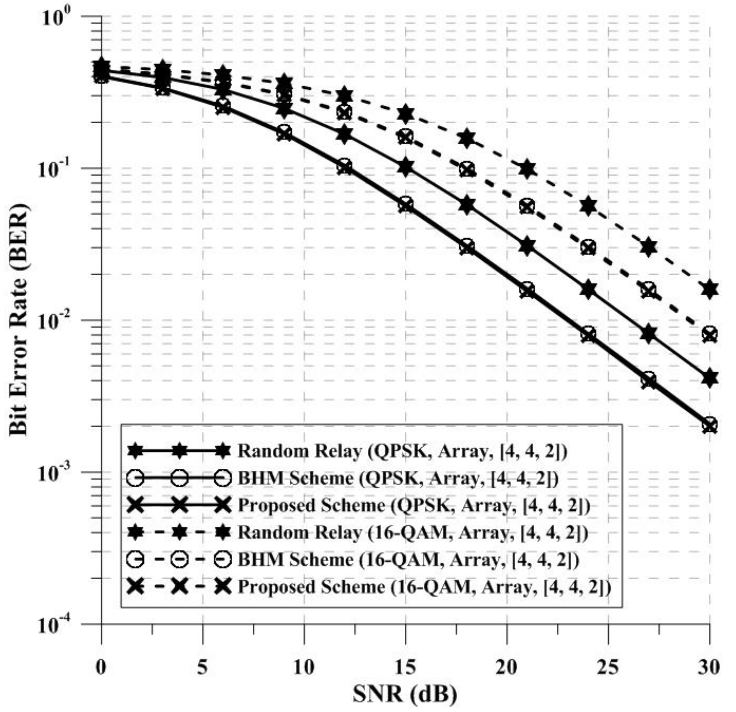
Figure 8, the ‘Array’ means that the antennas of the BS and relays are arranged in an array ( 2 × 2 ) . As shown in Figure 8, the random relay has lowest BER performance, and the proposed relay selection scheme has BER performance similar to the BHM scheme. Therefore, the proposed relay selection scheme can select the appropriate relay using only 3D channel information between the BS and relays.
As shown in Figure 7 and Figure 8, the proposed scheme has similar BER performance with the optimal relay selection scheme (BHM scheme) and has better BER performance than the random relay selection scheme in 3D channel environment.
The proposed relay selection scheme has higher performance than the random relay selection scheme without considering any factors, since the proposed relay selection scheme selects an appropriate relay using the singular values of the channel matrix between the BS and relays. Additionally, in the BHM scheme (optimal relay selection scheme), the BS must know both the channel information between the BS and relays, and between the relays and UE. Therefore, the BHM scheme is an optimal relay selection scheme among the various relay selection schemes but it is very complicated. The proposed relay selection scheme selects one relay by using only the singular values of the channel matrix between the BS and relays. In other words, in the proposed relay selection scheme, even if the BS only knows the channel information between the BS and relays, an appropriate relay can be selected. As a result, the proposed relay selection scheme has similar BER performance of the BHM scheme, and can select an appropriate relay more easily than the BHM scheme.
The proposed relay selection scheme provides the method for selecting the appropriate relay by using only the channel information between the BS and relays, unlike the conventional schemes. Therefore, the proposed scheme can select the appropriate relay more simply than the conventional schemes. In addition, the proposed scheme can select the appropriate relay in the 2D channel and 3D channel environment. As a result, the proposed relay selection scheme can improve the reliability of the system by selecting the appropriate relay and mitigating the error propagation problem of the multi-hop transmission for MU-MIMO system.

6. Conclusions

This paper proposes a method to select an appropriate relay in DF-based multi-hop transmission of MU-MIMO system. The DF-based multi-hop transmission system can degrade the system performance due to the error propagation. In order to improve the system performance by mitigating the error propagation problem, the DF-based multi-hop transmission system requires selection schemes. Therefore, there are many studies related to the relay selection. Among the various relay selection schemes, the BHM scheme is the optimal relay selection scheme [13]. In the BHM scheme, the BS must know both the channel information between the BS and relays and between the relays and UE in order to select an appropriate relay. Therefore, the BHM scheme has very high BER performance, but it is complicated. The proposed relay selection scheme selects one relay using only singular value of the channel matrix between the BS and relays. In the proposed relay selection scheme, the singular values are obtained through the SVD of the channel matrix between the BS and relays. Then, the relay having the largest sum of the singular values is selected. Therefore, in the proposed relay selection scheme, the BS can select an appropriate relay even if the BS only knows the channel information between the BS and relays. In addition, the proposed relay selection scheme provides a method to select an appropriate relay for multi-hop transmission in a 3D channel environment as well as the conventional 2D channel environment. The conventional and proposed relay selection scheme can mitigate the error propagation problem of the DF-based multi-hop transmission system, but the problem still remains. Therefore, we plan to study one that can select an appropriate relay through AOA-based localization estimation and beamforming in a system using a linear and array antenna, and reliably mitigate the error propagation by increasing the SNR of the received signal. The simulation results show that the proposed relay selection scheme has higher BER performance than the random relay selection scheme and similar to the BHM scheme. As a result, the proposed relay selection scheme can select an appropriate relay more easily than the conventional relay selection scheme using only channel information between the BS and relays.

Author Contributions

W.-C.K. proposed a relay selection scheme for MU-MIMO based multi-hop transmission system and performed computational simulations; M.-J.P. performed simulation of the conventional system and schemes; H.-K.S. gave feedbacks about modified algorithm and all simulation results. Also, H.-K.S. provided the experimental materials for better computational simulations and revised critical errors of the manuscript.

Acknowledgments

This work was supported by the MSIT(Ministry of Science and ICT), Korea, under the ITRC(Information Technology Research Center) support program(IITP-2018-0-01423) supervised by the IITP(Institute for Information & communications Technology Promotion) and was supported by Institute for Information & communications Technology Promotion(IITP) grant funded by the Korea government(MSIT) (No.2017-0-00217, Development of Immersive Signage Based on Variable Transparency and Multiple Layers).

Conflicts of Interest

The authors declare no conflict of interest.

References

  1. Hwang, W.J.; Kang, W.P.; Jang, J.H.; Choi, H.J. A multi-user interference detection method for MU-MIMO transmission in LTE advanced system. In Proceedings of the 2012 Asia-Pacific Conference on Communications (APCC), Jeju Island, Korea, 15–17 October 2012; pp. 169–172. [Google Scholar]
  2. Spencer, Q.H.; Peel, C.B.; Swindlehurst, A.L.; Haardt, M. An introduction to the multi-user MIMO downlink. IEEE Commun. Mag. 2004, 42, 60–67. [Google Scholar] [CrossRef]
  3. Peel, C.B.; Hochwald, B.M.; Swindlehurst, A.L. A vector-perturbation technique for near-capacity multiantenna multiuser communication-part 1: Channel inversion and regularization. IEEE Trans. Commun. 2005, 53, 195–202. [Google Scholar] [CrossRef]
  4. Mondal, B.; Thomas, T.A.; Ghosh, A. MU-MIMO system performance analysis in LTE evolution. In Proceedings of the 2010 Annual IEEE International Symposium on Personal, Indoor and Mobile Radio Communications, Instanbul, Turkey, 26–30 September 2010; pp. 1510–1515. [Google Scholar]
  5. Kang, J.; Lee, K.; Myung, J.; Kang, J. Multiuser MIMO Downlink with linear precoding for full multiplexing gain. In Proceedings of the 2010 IEEE Vehicular Technology Conference, Ottawa, ON, Canada, 6–9 September 2010; pp. 1–5. [Google Scholar]
  6. Jiang, M.; Hosseinian, M.; Lee, M.; Stern-Berkowitz, J. 3D channel model extension and characteristic study for future wireless systems. In Proceedings of the 2013 Annual International Symposium on Personal, Indoor, and Mobile Radio Communications (PIMRC), London, UK, 8–11 September 2013; pp. 41–46. [Google Scholar]
  7. Ademaj, F.; Taranetz, M.; Rupp, M. 3GPP 3D MIMO channel model: A holistic implementation guideline for open source simulation tools. EURASIP J. Wirel. Commun. Netw. 2016, 2016, 1–14. [Google Scholar] [CrossRef]
  8. Ji, H.; Kim, Y.; Lee, J.; Onggosanusi, E.; Nam, Y.; Zhang, J.; Lee, B.; Shim, B. Overview of Full-Dimension MIMO in LTE-Advanced Pro. IEEE Commun. Mag. 2017, 55, 176–184. [Google Scholar] [CrossRef] [Green Version]
  9. Demeechai, T.; Kukieattikool, P. Performance limit of AOA-based localization using MIMO-OFDM channel state information. EURASIP J. Wirel. Commun. Netw. 2017, 1, 1–10. [Google Scholar] [CrossRef]
  10. Yu, Y.; Zhang, J.; Smith, P.J.; Dmochowski, P.A. Theoretical analysis of 3-D channel spatial correlation and capacity. IEEE Commun. Lett. 2017, 22, 420–423. [Google Scholar] [CrossRef]
  11. Nosratinia, A.; Hunter, T.E.; Hedayat, A. Cooperative communication in wireless networks. IEEE Commun. Mag. 2004, 42, 74–80. [Google Scholar] [CrossRef]
  12. Song, J.-H.; Song, H.-K. Adaptive DF relaying scheme based on CDD for multi-hop networks with multiple relay terminals. IEICE Trans. Commun. 2011, E94-B, 1085–1088. [Google Scholar] [CrossRef]
  13. Kim, W.-C.; Paek, M.-J.; Ro, J.-H.; Song, H.-K. Adaptive CoMP with spatial phase coding for interference mitigation in the Heterogeneous network. Appl. Sci. 2018, 8, 631. [Google Scholar] [CrossRef]
  14. Ahn, Y.-S.; Choi, S.-B.; Jeon, J.; Song, H.-K. Adaptive relay selection and data transmission scheme for cooperative communication. Wirel. Pers. Commun. 2016, 91, 267–276. [Google Scholar] [CrossRef]
  15. Kim, S.-Y.; Kim, W.-C.; Song, H.-K. Relay selection scheme for improved performance in the wireless communication system based on OFDM. IEICE Trans. Fundam. Electr. Commun. Comput. Sci. 2017, E100-A, 2200–2203. [Google Scholar] [CrossRef]
  16. Choi, S.-B.; You, Y.-H.; Song, H.-K. Efficient partial single relay selection scheme for wireless communications. IEICE Trans. Fundam. Electr. Commun. Comput. Sci. 2015, E98-A, 923–926. [Google Scholar] [CrossRef]
  17. Bohnke, R.; Wubben, D.; Kuhn, V.; Kammeyer, K.-D. Reduced complexity MMSE detection for BLAST architectures. In Proceedings of the 2003 IEEE Global Telecommunications Conference, San Francisco, CA, USA, 1–5 December 2003; pp. 2258–2262. [Google Scholar] [Green Version]
  18. Pollet, T.; Van Bladel, M.; Moeneclaey, M. BER sensitivity of OFDM systems to carrier frequency offset and Wiener phase noise. IEEE Trans. Commun. 1995, 43, 191–193. [Google Scholar] [CrossRef]
  19. Pollet, T.; Moeneclaey, M. Synchronizability of OFDM signals. In Proceedings of the 1992 GLOBECOM, Singapore, Singapore, 14–16 November 1995; pp. 2054–2058. [Google Scholar]
  20. Chronopoulos, S.K.; Tatsis, G.; Kostarakis, P. Turbo Coded OFDM with large number of subcarriers. J. Signal Inf. Process. 2012, 3, 161–168. [Google Scholar] [CrossRef]
  21. Chronopoulosa, S.K.; Votisa, C.; Raptisa, V.; Tatsisa, G.; Kostarakisa, P. In depth analysis of noise effects in orthogonal frequency division multiplexing systems, utilizing a large number of subcarriers. In Proceedings of the 2010 AIP Conference, Alexandroupolis, Greece, 9–13 September 2009; pp. 967–972. [Google Scholar]
  22. Cho, Y.S.; Kim, J.; Yang, W.Y.; Kang, C.G. MIMO-OFDM Wireless Communications with MATLAB; John Wiley & Sons: Hoboken, NJ, USA, 2010. [Google Scholar]
Figure 1. The system model for proposed relay selection scheme.
Applsci 08 01747 g001
Figure 2. The system model of the DF relaying scheme.
Applsci 08 01747 g002
Figure 3. The system model of the MU-MIMO scheme.
Applsci 08 01747 g003
Figure 4. The 3D channel model.
Applsci 08 01747 g004
Figure 5. The BER performance of the proposed and conventional schemes in 2D channel environment ( N t = 2 , N r = 2 , N U E = 1 ) .
Applsci 08 01747 g005
Figure 6. The BER performance of the proposed and conventional schemes in 2D channel environment ( N t = 4 , N r = 4 , N U E = 2 ) .
Applsci 08 01747 g006
Figure 7. The BER performance of the proposed and conventional schemes in 3D channel environment (Linear antenna).
Applsci 08 01747 g007
Figure 8. The BER performance of the proposed and conventional schemes in 3D channel environment (Array antenna).
Applsci 08 01747 g008

