Abstract
For the investigation of processes happening on the time scale of the motion of bound electrons, well-controlled X-ray pulses with durations in the few-femtosecond and even sub-femtosecond range are a necessary prerequisite. Novel free-electron lasers sources provide these ultrashort, high-brightness X-ray pulses, but their unique aspects open up concomitant challenges for their characterization on a suitable time scale. In this review paper we describe progress and results of recent work on ultrafast pulse characterization at soft and hard X-ray free-electron lasers. We report on different approaches to laser-assisted time-domain measurements, with specific focus on single-shot characterization of ultrashort X-ray pulses from self-amplified spontaneous emission-based and seeded free-electron lasers. The method relying on the sideband measurement of X-ray electron ionization in the presence of a dressing optical laser field is described first. When the X-ray pulse duration is shorter than half the oscillation period of the streaking field, few-femtosecond characterization becomes feasible via linear streaking spectroscopy. Finally, using terahertz fields alleviates the issue of arrival time jitter between streaking laser and X-ray pulse, but compromises the achievable temporal resolution. Possible solutions to these remaining challenges for single-shot, full time–energy characterization of X-ray free-electron laser pulses are proposed in the outlook at the end of the review.
1. Introduction—Laser-Assisted Time-Domain Characterization at Free-Electron Lasers
Availability of ultrashort, high-brightness X-ray pulses
Exploring fundamental quantum building blocks of nature and their interactions on time scales of molecular, atomic and even electronic motion, has led to the development of scientific instruments with steadily enhanced spatial and temporal resolution. For modern day optical tools, that historical path reaches from the discovery of X-rays and their properties just before the turn to the 20th century [1], via synchrotron radiation detected as parasitic electron energy-loss effect in the middle of the last century [2], to the parasitic operation at electron synchrotrons [3]. Next came dedicated beamlines built as multiple synchrotron radiation stations around storage rings [4], and finally high-brightness X-ray beams through periodically alternating magnetic insertion devices [5] were achieved. Today, the most recent additions to the arsenal of X-ray physics stem from high-order harmonic generation (HHG) by intense few-cycle optical laser pulses [6] and from the realization of the concept of free-electron lasers (FELs) [7,8] at large-scale facilities around the world. These FEL sources provide ultrashort high-brightness pulses from the soft X-ray regime, like the free-electron laser in Hamburg (FLASH), operated by DESY in Germany [9] and the free-electron laser radiation for multidisciplinary investigations (FERMI) seeded FEL in Trieste, Italy [10], to the hard X-ray range, e.g., the Linac Coherent Light Source (LCLS) at the SLAC National Accelerator Laboratory in California, USA [11] and the SPring-8 angstrom compact free-electron laser (SACLA) in Japan [12], among others [13,14]. Future machines, using novel laser-based accelerator concepts promising much more compact X-ray sources [15,16,17,18] or utilizing superconducting linear accelerators for higher repetition rates in the MHz range (e.g., the European XFEL in Germany [19] or LCLS-II in the USA [20]), are expected to generate X-ray pulses with few- to sub-femtosecond durations as well, and are likewise crucially dependent on a precise X-ray pulse metrology.
Well-controlled X-ray pulses with durations shorter than few tens of femtoseconds that are currently produced at X-ray free-electron lasers (XFELs) are a necessary prerequisite for the investigation of ultrafast processes on the time scale of the motion of bound electrons, as have been successfully studied in seminal high harmonic generation-based attosecond experiments [21,22,23,24,25,26,27,28,29,30,31]. A number of schemes have been proposed and implemented over the last decade to shorten the pulse durations at XFELs to the few-femtosecond or even sub-femtosecond range, many of them based on the principle that the X-ray pulse duration is related to the driver electron bunch length. One approach, the so-called ‘slotted spoiler’, was invented at the LCLS and provides few-femtosecond to sub-femtosecond pulses [32,33]. The working principle of this scheme is illustrated in Figure 1 on the left. A thin foil with a narrow vertical slit is introduced into the electron beam path in one of the magnetic bunch compressor chicanes and spoils the beam quality (emittance) of the largest part of the spatially chirped electron bunch via Coulomb scattering. Only the small central slice of the bunch passes unhindered through the slit and will subsequently experience efficient FEL amplification in the undulator. Other proposed methods involve the modulation of the electron bunch with a high-power, few-cycle optical laser in a single-period wiggler before the FEL undulator to induce a pronounced energy modulation along the electron bunch and a sub-femtosecond spike in the electron peak current. Thus, only a small region of the bunch contributes efficiently to the X-ray amplification process and generates an attosecond spike of X-ray radiation, see for example [34,35,36,37].
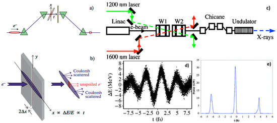
Figure 1.
Sketch of the working principles for few-femtosecond and sub-femtosecond X-ray free-electron lasers (XFEL) pulse generation. (a) The upper part shows the spatially chirped electron bunch at the center of the compressor chicane with a marked tilt with respect to the direction of propagation. (b) The slotted foil is depicted, leaving only a narrow central region of the bunch pass unspoiled ((a,b) are reproduced with permission from [32], Copyright American Physical Society, 2004). (c) The upper panel shows a schematic of the components involved in attosecond X-ray pulse production. W1 and W2 are two wiggler sections that generate the modulation of the electron bunch by interaction with high-power, few-cycle optical lasers. (d) In panel, the calculated energy modulation of the electrons along the electron bunch produced in the interaction with a few-cycle, 1200 nm laser pulse in a wiggler magnet is shown. (e) The resulting attosecond X-ray power profile after 50 m of propagation in the undulator is plotted in panel ((c–e) are reprinted under the terms of the Creative Commons Attribution 3.0 License from [38], 2005).
Ultrafast temporal characterization for novel attosecond X-ray experiments
From the perspective of the scientific researcher, the special opportunities opened up by free-electron laser sources lie in their extreme spatial and temporal coherence, combined with the achievable ultrahigh intensity, broadly adjustable photon energy range and ultrashort pulse duration. Using these sources will ultimately enable novel ultrafast experiments with attosecond temporal resolution, like site-specific X-ray pump/X-ray probe measurements [39] and serial crystallography for studies of structural dynamics [40], or atomic-scale diffractive imaging as proposed by Yakovlev et al. [41] on energy-selected target states of molecules, surfaces and nanoparticles. Recent experiments with high-energy electrons [42,43] and X-rays [44] have already demonstrated the first steps towards this so-called molecular movie on the femtosecond scale. For an extensive overview of the experimental capabilities and scientific achievements during the last years at LCLS see Ref. [45].
To realize the goal of time-resolved X-ray measurement with attosecond resolution, one first has to consider the special complexities arising from the work with attosecond XFEL pulses, foremost the characterization of their temporal structure. As with any signal based on the self-amplified spontaneous emission (SASE) process [46], the temporal shape of each subsequent single XFEL pulse is implicitly different from the previous one, demanding a single-shot measurement technique for its investigation. However, until recently no direct experimental determination of the structure of these X-ray pulses in the time domain was accomplished. Therefore, in this paper we want to concentrate on the unique aspects and concomitant challenges that arise from the availability of X-ray free-electron laser pulses of femtosecond and even sub-femtosecond durations and their characterization on a suitable time scale.
Indirect measurement methods
SASE XFEL pulse durations have been indirectly inferred (see also the review in Ref. [47]) from measurements on the electron bunch length before the undulator [48] or from statistical analysis of the spectral coherence properties of the ultrashort X-ray pulses [49]. However, these characterization techniques cannot provide single-shot information on the temporal structure of the X-ray pulses and only statistically averaged quantities for possible pulse length predictions can be derived from these measurements. Furthermore, studies of fundamental ionization processes [50] and sideband measurements, also reported on in this review [51], have revealed a clear deviation of the actual X-ray pulse duration from the one inferred from electron bunch length measurements. A substantial improvement of the temporal resolution and the reliability for X-ray pulse characterization has been achieved by X-band radiofrequency transverse deflector (XTCAV) measurements on the spent electron bunch after propagation through the undulator [52]. Very recently, the concept of machine learning has successfully been used for the prediction of XFEL pulse properties, based on the online measurement of numerous accelerator specific parameters [53]. Nevertheless, these techniques all constitute indirect characterization methods and need direct time domain measurements for their exact calibration.
Direct measurement methods
The usual characterization techniques for ultrashort optical pulses are not readily transferrable to the X-ray regime. Autocorrelation setups have been developed for VUV wavelengths [54,55], but are hard to establish in the X-ray range due to the corresponding relatively small nonlinear interaction cross sections and phase-matching bandwidth for most materials, together with the lack of suitable beam splitting and combining optics and the ensuing stability issues. Other standard cross-correlation schemes like spectral phase interferometry for direct electric-field reconstruction (SPIDER) [56] are, on the other hand, hindered by the requirement for reliable phase modulators for X-ray pulses or are restricted to the implementation at seeded FELs [57].
Various methods with solid state targets have been used for FEL characterization, which are based on an FEL-induced transient change of the refractive index of material, as demonstrated in Ref. [58]. The most common scheme remains that of probing the cross-correlation between FEL and IR pulses, and single-shot streaking geometries have been implemented (see e.g., [59]). In general, their temporal resolution is inherently limited by the electron relaxation dynamics in condensed matter, and these measurements are usually destructive towards the X-ray beam. Thus, these concepts are not part of this review dealing specifically with ultrashort XFEL pulse characterization on the femtosecond and sub-femtosecond time scales.
For the sake of completeness, we should remind the reader of the particularly noteworthy four-wave mixing scheme pioneered by Masciovecchio and co-workers [60,61], in which the interaction of three photons with matter results in the generation of a fourth “signal” photon whose color and direction fulfils the phase-matching conditions; this method probes the third-order nonlinear susceptibility χ(3), and although technically more complicated has an enormous advantage in terms of background suppression. Let us finally note that in the framework of high harmonic generation, a four-wave mixing scheme has been successfully used with a gaseous target [62].
In light of the reckoning above, the method of choice to directly measure the ultrashort XFEL pulse duration is the concept of time-resolved optical laser-dressed photoelectron (PE) spectroscopy in gaseous media, which is a well-established technique for temporal characterization of attosecond pulses in the XUV spectral region. This scheme has been theoretically described in [63,64] and successfully demonstrated in numerous time-resolved measurements of laser-based XUV sources [65,66,67]. This setup, shown exemplarily in Figure 2, provides a direct, non-invasive, single-shot, low-photon intensity, photon energy-independent and high-repetition rate-compatible pulse characterization method. The essential parts of the theory for the purpose of the temporal XFEL pulse characterization shall be briefly discussed in the following section.
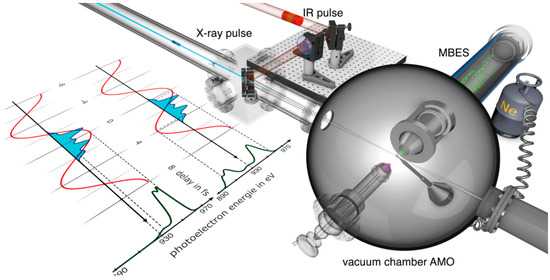
Figure 2.
General setup for laser-dressed photoelectron spectroscopy. Typical experimental setup and measurement principle for a two-color ultrafast temporal characterization measurement. The picture shows the experimental setup in the atomic, molecular and optical science (AMO) hutch at the Linac Coherent Light Source (LCLS). The X-ray laser and the near-infrared (NIR) dressing laser are coupled into the vacuum chamber and are collinearly focused onto a neon gas target. The generated photoelectrons are then energy resolved with a magnetic bottle electron spectrometer. The inset on the left depicts two distinctive cases of temporal overlap of the XFEL with respect to the streaking field, one at the zero crossing and one at a maximum of the NIR vector potential. The respective photoelectron spectra are also shown. More details are given in the text in Section 3.1.1 and in Figure 7 (reproduced with permission from [69], Copyright Nature Publishing Group, 2014).
As will be shown, a number of variants of this technique exist, each with their own individual merits for a specific range of X-ray pulse durations and required temporal resolution. While the method relying on the sideband measurement (Section 2) is relatively easy to implement with standard Ti:sapphire laser systems, its information about single X-ray shot characteristics is limited. On the other hand, longer laser wavelengths, only indirectly accessible via optical parametric amplification (OPA) [68], are preferable to avoid the breakdown of the streaking regime (cf. Section 3.1.1 of this paper). This is typically the case, when the X-ray pulse duration is longer than half the oscillation period of the streaking field, corresponding to only 1.3 fs for the gain peak wavelength of Ti:sapphire at 795 nm. Finally, using terahertz (THz) fields with a very long optical period (Section 3.1.2 and Section 3.2) alleviates the problem of arrival time jitter between streaking laser and X-ray pulse, but compromises the achievable temporal resolution. Possible solutions to these remaining issues for single-shot, full time–energy characterization of XFEL pulses are proposed in the outlook at the end of the paper.
2. Sideband Method for X-ray Pulse Characterization
Temporal pulse characterization with photoelectrons
Two-color photoionization experiments using the combination of intense free-electron laser femtosecond pulses in the extreme ultraviolet (XUV) to X-ray wavelength range and optical or NIR pulses offer great potential to determine the temporal characteristics, i.e., pulse durations and the relative temporal arrival time, of the FEL pulses.
Although studies of two-color photoionization of atoms in weak resonant optical/NIR fields are well established at synchrotron radiation facilities [70], it is only with the availability of short wavelength FELs that experiments have been performed, in which electrons ejected by the XUV or X-ray field can also be effectively “dressed” by the intense NIR laser field. Overlapping the two intense ultrashort pulses temporally and spatially in a gaseous target leads to the appearance of additional structures in the photoelectron spectrum, which are the clear indication of the two-color process. Ionization by the XUV or soft X-ray pulse creates electrons with typically a few tens and up to few hundreds of eV kinetic energy. The additional interaction with the intense NIR fields induces absorption or emission of NIR photons resulting in extra lines in the photoelectron spectrum (Figure 3a) spaced by the photon energy of the NIR photons (1.55 eV for 800 nm) (e.g., [71]). These lines are called ‘sidebands’ and are ideal candidates for a first characterization of the FEL pulses. In addition, the quasi-monochromaticity of the FELs makes it possible to observe, for high dressing fields, absorption and emission of more than one NIR photon [72,73], avoiding interference effects present in similar experiments with broader-bandwidth XUV pulses of high-harmonic-generation sources [74]. In the following we will always use the term ‘X-ray’ for the FEL pulses, meant to cover the whole spectral range from XUV (>10 eV) over soft X-rays (>100 eV) to hard X-rays (>5 keV), to discern them from other short-wavelength sources as e.g., high harmonic-generated XUV pulses.
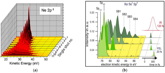
Figure 3.
Single-shot sideband spectra. (a) Single-shot electron spectra in the region of the Ne 2p−1 photoemission line sorted with respect to different NIR intensities (reprinted with permission from [72], Copyright IOP Publishing, 2010). (b) Single-shot electron spectra in the region of the Xe 5p−1 photoemission line and the high-energy sidebands, taken at the nominal temporal overlap. Due to the relative arrival time jitter the actual timing varies by more than the pulse durations. The sidebands are used to get information about the actual degree of temporal (and spatial) overlap. In addition, a schematic of the temporal overlap between FEL and NIR pulses is shown (reprinted with permission from [75], Copyright AIP Publishing, 2007).
Besides using the sideband structures in the photoelectron spectra for the study of photoionization dynamics in strong external fields, the sideband intensity provides a clear indication of the temporal and spatial overlap between the FEL and the NIR laser beams. Since sidebands appear only when the two laser pulses overlap (see Figure 3b), their intensity exhibits a characteristic dependence on the relative time delay between the ionizing and the dressing pulses. For free-electron lasers based on the SASE process, such as FLASH, LCLS and SACLA, the X-ray and NIR pulses are generated separately by the FEL and the optical laser system. These two independent sources are only linked by a common externally working synchronization system [76]. Although the synchronization has been improved tremendously during the last years <30 fs root mean square (rms) [77], the pulse-to-pulse arrival time fluctuations exceed very often the pulse durations of the two pulses. The analysis of electron spectra for many individual pulses provides direct information about the temporal stability and can be used as inherent time marker for time-resolved pump/probe experiments.
The actual sideband amplitude depends on several parameters. First, good spatial overlap is crucial for the sideband generation. In addition, a meaningful analysis of sideband spectra is only possible when the X-ray focus is significantly smaller compared to the NIR focal spot size. Under such conditions the electrons are created only in the maximal field of the NIR pulse and are all exposed to (almost) the same NIR field strength. Nonetheless, pointing fluctuations of either of the two beams present a severe limitation for the practical use of the method.
Second, temporal overlap has to be assured, since the sidebands correspond to free–free transitions in the ionization continuum and both pulses have to interact with the electronic state at the same time. When the intensity conditions are such that a single sideband is generated, the interaction is determined by one X-ray and one NIR photon yielding a linear dependence on the relative overlap of the two pulses for the resulting sideband amplitude [78]. However, at high NIR intensities more than one sideband is present, implying the involvement of several NIR photons in the sideband formation process at the same time. This leads to a nonlinear response of the observed electron spectra, with a strong dependence on the intensity of the driving NIR laser. Thus, the sideband amplitudes are no longer linearly connected to the temporal overlap. Therefore, quantitative information about the X-ray pulse duration can only be extracted by comparing the sideband features to a theoretical model.
The experimental line profiles can be fitted with a simplified analytical model based on the so-called soft-photon approximation (SPA), allowing us to simulate the sideband spectrum [79]. In general, the SPA gives excellent agreement with experimental data and can match the more elaborate non-perturbative methods such as the time-dependent Schrödinger equation (TDSE) when the electron kinetic energy is large compared to the photon energy of the dressing field [51,79,80,81]. The simulated sideband spectra are defined by four parameters: duration, , and intensity , of the NIR laser pulse as well as duration (and shape) of the FEL pulse and, finally, the relative temporal delay between the two pulses δ. The NIR pulse width and intensity can be determined with good accuracy before the experiment leaving and δ as parameters to be determined during the measurement [51].
The sideband spectra can be analyzed in two ways. One approach comprises a statistical analysis of the single shot spectra while setting the relative delay to a fixed value, namely at nominal maximum overlap of X-ray and NIR pulses. Due to the inherent arrival time fluctuations the sideband amplitudes and the number of sidebands vary significantly from shot to shot. However, looking at the frequency distribution of the sideband amplitudes (histogram), information about the average temporal jitter and the X-ray pulse duration can be extracted [51,75]. Secondly, by changing the relative arrival time between the two pulses successively, a cross-correlation curve is acquired as shown in Figure 4 [82]. Again, the width of the correlation is determined by the dominant parameters of the X-ray and the NIR pulse durations as well as by the relative arrival time jitter.
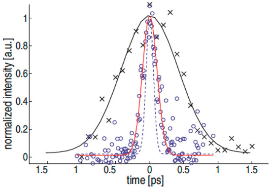
Figure 4.
Sideband amplitudes. The amplitude of the first-order sideband measured in Xe is plotted as function of the set delay between the NIR laser and the free-electron laser in Hamburg (FLASH) free-electron laser (FEL) pulse. The uncorrected X-ray pump/NIR probe delay scan (x, fit as solid black line) is entirely dominated by the relative arrival time jitter and shows a width of 410 fs rms. A measurement technique based on electro-optical sampling [82] is able to provide an independent measurement of this jitter and can thus be used to correct the arrival time. This leads to an about 4 times narrower correlation width of 100 fs rms (o, fit as solid red line), which is already close to the simulated jitter-free case (dashed blue line). Normalized signal amplitudes are used throughout these plots (reproduced with permission from [82], Copyright AIP Publishing, 2009).
In this scheme, photoelectrons generated via two-photon ionization in a single shot were measured at FLASH [9,83] using a magnetic bottle electron spectrometer (MBES) [84]. This efficient type of spectrometer allows the collection of all electrons emitted over the complete solid angle for small kinetic energies <100 eV [85], and still over approximately 0.8 sr corresponding to a 30° half-angle emission cone at higher electron kinetic energies around 0.8 keV [51]. Hence, the MBES setup can be applied to low-density targets and enables, in the case of the intense FEL beam, an analysis of the photoionization process on a shot-to-shot basis [75,84]. The best energy resolution, 1–2% of the electron kinetic energy, is achieved by decelerating the electrons with the aid of electrostatic retardation fields at the entrance of the flight tube.
First experiments were mainly able to reveal the effect and show the NIR pulse duration, which was at least an order of magnitude larger than the other two parameters [78]. By reducing the NIR pulse duration from several picoseconds to about 120 fs it was possible to determine the relative arrival time jitter [84]. Eventually, by minimizing the timing jitter and NIR pulse duration even further, the final goal was reached to directly determine the X-ray pulse duration of a SASE XFEL [51].
For seeded FELs like FERMI, the relative arrival time jitter is strongly reduced in contrast to unseeded (SASE) FELs. Thus in this case the jitter is significantly less than the X-ray and NIR pulse durations, allowing for an even more precise measurement of the X-ray pulse duration [86]. Generally, the sideband method has been extensively used at FERMI to characterize the pulse length, and its results are in agreement with a complementary method and with theory [59]. A few distinctive aspects of its use at FERMI are related to the fact that this is a seeded source, resulting in predictable timing and coherence of the pulses. The measurements are intrinsically jitter-free, and concentrated on characterizing the pulse properties as a function of machine parameters. In particular, pulse coherence was exploited to implement a compression scheme [87], and the pulse duration was measured with the sideband method.
Sideband formation of Auger electrons
The typical bandwidth of a SASE FEL pulse is in the range of 0.1 to 1% of the nominal photon energy. For the photon energies at FLASH this results in a width less than the spacing of the sidebands (see Figure 3), such that they can be analyzed individually. On the other hand for shorter wavelengths in the X-ray regime as available at LCLS, the linewidth of the XFEL radiation can exceed the separation of the sidebands significantly (e.g., a linewidth of 7 eV at a photon energy of 1 keV was measured in Ref. [51]). In this case the emission of Auger electrons rather than photoelectrons can be measured instead, but still a de-convolution procedure and a comparison with simulated spectra has to be applied to extract the information about the X-ray pulse duration (Figure 5).
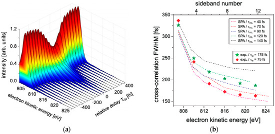
Figure 5.
Auger sideband spectra. (a) NIR-dressed neon Auger electron energy spectra as a function of the relative delay time δ between the NIR ( = 100 fs) and the X-ray pulses ( = 75 fs); (b) Comparison of experimentally obtained cross-correlation widths with those calculated within the soft-photon approximation (SPA) using the following parameters (in full width at half maximum (FWHM)): = 40 fs–140 fs, = 100 fs and δ = 140 fs, INIR = 1.2 × 10¹² W cm−2 (reproduced with permission from [51], Copyright IOP Publishing, 2011).
X-ray pulse characterization including polarization
Sidebands were also used to determine other characteristics of the X-ray photon beam, namely its degree of polarization. For the first experiment using linearly polarized FEL and NIR pulses, it was demonstrated that the sideband intensity depends in a sensitive and characteristic way on the relative orientation between the two linear polarization vectors [88]. Since this dichroic effect is caused by a different ratio of the partial waves contributing to the outgoing electron (e.g., s- and d-waves in case of a two-photon ionization in He), which can be calculated very precisely by theory, it can in turn also be used to determine the degree of polarization of the FEL beam. This was demonstrated at FERMI, the first seeded FEL producing circularly polarized X-ray pulses [10]. By measuring the circular dichroism in the electron angular distribution of the first sideband (Figure 6), it was possible to determine the degree of circular polarization as well as the sign of the helicity. The measured value for the polarization at the experimental station (about 95%) [89] is in excellent agreement with estimates, taking into account an almost perfect polarization at the end of the undulator and the contribution from the optical elements of the beamline.
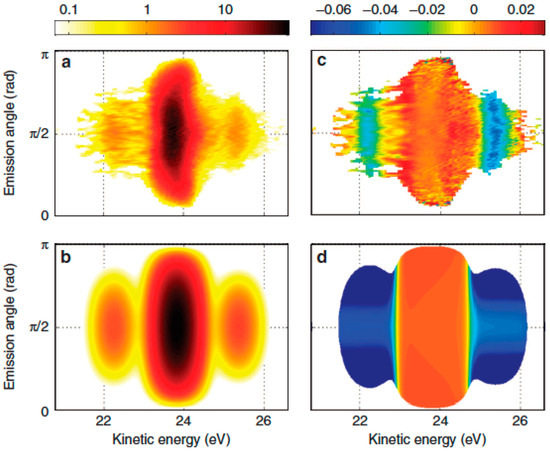
Figure 6.
Angle-resolved spectra and dichroism. Experimental (top) and simulated (bottom) angle- and energy-resolved electron spectra (a,b) and circular dichroism (c,d) in He 1s photoionization at low NIR laser intensity (7.3 × 10¹¹ Wcm−2). The respective intensities are indicated by the color scales on top of the graphs (reproduced with permission from [89], Copyright Nature Publishing Group, 2014).
A similar method, i.e., the measurement of the circular dichroism in the sideband yields of electrons emitted from the inner shell of molecular oxygen, was also applied for the determination of the degree of circular polarization produced by the DELTA undulator at LCLS [90]. Here, the above discussed issue concerning the sideband separation in relation to the relatively large bandwidth of a SASE based XFEL was overcome by dressing the molecules with a frequency-doubled optical laser, ensuring a sufficient energy spacing of the individual sidebands.
All these examples show that the measurements of sidebands, which are produced by the simultaneous interaction of the X-ray pulse and the NIR dressing field, provide detailed information about the X-ray pulse characteristics, especially on the pulse duration, the relative arrival time and its degree of polarization. This will certainly be used in future experiments at new, not yet well-characterized FEL facilities, but also the investigation of the dynamics of the two-color photoionization in itself is still of large interest. These measurements will permit a focus on particular aspects of the ionization process, e.g., the intensity dependence of the electron angular distribution or near-threshold phenomena [86,91].
3. Linear Streaking Measurements at Free-Electron Lasers
The method of sideband generation for the temporal characterization of X-ray pulses is valid in the regime where the X-ray pulse duration is longer than the cycle period of the applied dressing field [92]. For very short X-ray pulses, of few-femtosecond or even sub-femtosecond duration, a different approach is needed, one that relies on the ultrafast changes of the electric dressing field itself instead of its cycle-averaged intensity. In this section we will first discuss the characterization of soft X-ray pulses (Section 3.1), before describing the metrology of hard X-rays in 3.2.
3.1. Streaking Measurements of Soft X-ray Pulses
3.1.1. Infrared Streaking Experiments at Free-Electron Lasers
The presented diagnostic utilizes time-resolved photoelectron spectroscopy (also called laser-dressed photoionization), a technique that was originally developed for temporal characterization of attosecond XUV pulses from higher-order harmonic generation [66]. This technique is applicable over a broad range of photon energies produced at XFELs and can be applied to pulses ranging from several femtoseconds to hundreds of femtoseconds. The measurement works on a single-shot basis, requires only a small fraction of the available XFEL power and can be used in parallel with an actual experiment, thus allowing tagging of the XFEL temporal properties and post-experimental single-shot sorting of acquired results.
Photoelectron streaking
In a conventional streak camera, the temporal profile of the incident photon pulse is imprinted on an electron wavepacket through photoemission. The electronic wavepacket—or in the case of high X-ray intensities—the burst of photoelectrons is subsequently deflected transversely by a fast voltage ramp. In this way, the temporal profile of the incident light pulse is mapped to the spatial coordinate on the electron detection screen. Due to energy dispersion in the photocathode and limitations in the gradient of the voltage ramp, the temporal resolution that can be achieved in a conventional streak camera is limited to the picosecond level.
To reach few-femtosecond or even sub-femtosecond resolution, a similar concept is applied in the attosecond streak camera. Here, the electromagnetic field of a near-infrared laser pulse is used to project the temporal properties of the X-ray pulse onto a photoelectron wavepacket created through ionization of a noble gas.
In state-of-the art attosecond physics, a carrier–envelope phase-stable few-cycle laser pulse at a central wavelength of 750 nm is used to generate attosecond XUV pulses through high harmonic generation [6]. The resultant XUV pulses are intrinsically synchronized to the field of the driving laser pulse, assumed to be fully coherent and additionally assumed to be identical from shot to shot. Attosecond streaking spectroscopy was first applied to characterize these XUV pulses.
Figure 7 shows a sketch of a typical experimental setup and illustrates the basic principle of streaking. The X-rays eject electrons from gas atoms via the photoelectric effect, and set them free with a kinetic energy equal to the X-ray photon energy minus the specific electron binding energy of the atomic shell. These photoelectrons can be described as free electron wave packets for our experimental conditions. The temporal structure of the generated photoelectron wave packet mimics that of the incoming XFEL pulse and its width is directly related to the X-ray pulse duration [93].
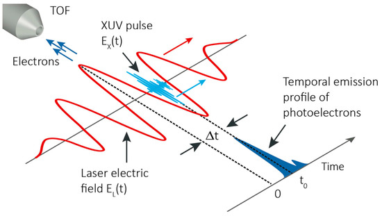
Figure 7.
Photoelectron streaking schematic. A short extreme ultraviolet (XUV) pulse generates a photoelectron bunch by ionizing noble gas atoms in the presence of a strong, few-cycle phase-stable NIR laser pulse. The XUV pulse and a NIR streaking pulse are precisely synchronized to each other. The current profile of the generated photoelectrons is given by the temporal structure of the ionizing XUV pulse. After photoionization, the electrons are subject to the electric field EL(t) of the NIR pulse which introduces a change in the final momentum distribution of the photoelectrons, depending on the instant of release t0 into the streaking laser field. The momentum change is detected with a time-of-flight (TOF) detector, which collects the electrons released along the direction of the streaking field polarization. The TOF is oriented such that it is axially aligned with the linear polarization of the laser and the XUV pulse. (Figure from [95]).
For the streaking measurement, the XUV pulse is focused on a noble gas target and temporally and spatially overlapped with an intense laser pulse (the temporal overlap can be adjusted by varying the optical path lengths between the XUV and NIR beams). Photoelectrons emitted during the streaking pulse are accelerated by an amount that depends on the instantaneous electric field amplitude or vector potential at the precise moment of ionization. For the polarization and detection oriented as in Figure 7, the shift in kinetic energy relative to the field-free case is given by:
where is the initial kinetic energy of the photoelectron, and and are the electron charge and mass. For extended XUV pulses, the variation of the laser electric field during the photoemission results in different final momenta for electrons ejected at different times. If the photoemission is confined to within one half-cycle of the laser field (1.25 fs for a carrier wavelength of 750 nm), the initial kinetic energy distribution of the photoelectrons released by the XUV pulse from the noble gas target will be uniquely broadened and shifted by the overlapping NIR streaking field. In general, the temporal profile and spectral phase of the ionizing XUV pulse can be determined by analyzing the broadening of the detected photoelectrons.
Scanning the relative delay between the ionizing XUV pulse and NIR streaking pulse allows consecutive measurements to be accumulated and a time-resolved spectrogram to be constructed. By applying an appropriate retrieval algorithm [94], the streaking pulse and XUV pulse, with temporal profile and spectral phase can be retrieved from this multi-shot measurement.
Experimental implementation
For the purpose of the streaking measurement at an XFEL an experiment was conducted (for further experimental details and theoretical background see [96]) at the atomic, molecular and optical science (AMO) instrumental end station at the LCLS [97]. It comprises a vacuum chamber within which an optical laser co-propagates with the XFEL and a magnetic bottle electron spectrometer [98], a high collection efficiency spectrometer that operates over a broad energy range capable of detecting the photoelectron spectra for every single shot.
The streaking laser was based on an optical parametric amplifier with the idler tuned to 2.4 μm central wavelength, horizontal polarization of the electric field, a pulse energy of ~30 μJ and a compressed pulse duration of ~50 fs full width at half maximum (FWHM). The output beam of the NIR laser was focused to a 1/e2 beam diameter of ~450 μm in the interaction region, yielding an optical intensity on target of roughly 4 × 10¹¹ W/cm2 or a corresponding peak vector potential of the streaking field of Apeak 0.18 atomic units. As a target for photoexcitation neon gas was streaming from a nozzle at a background pressure of ~1 × 10⁻⁷ mbar in the experimental chamber, and the photoelectrons were detected with the MBES.
The LCLS was working at a repetition rate of 60 Hz in the so-called ‘low-charge mode’, with an electron bunch charge of 20 pC around the point of maximum compression at ~10 kA, producing XFEL pulses expected to be of sub-10 femtosecond duration [11]. In order to further minimize the XFEL pulse duration, the ‘slotted spoiler’ [32] was inserted into the electron beam at the second bunch compressor chicane along the SLAC Linac ahead of X-ray generation in the undulator. With an XFEL photon energy of EX-ray = 1790 eV and a binding energy of EB = 870 eV for the 1s electron in neon, the central energy of the photoelectrons is distributed around the mean value of 920 eV with a standard deviation of ~2 eV rms. The bandwidth of the photoline, corresponding to the energy spread of the X-ray pulse, was measured to be ~3.3 eV rms. The various measured parameters of the XFEL are summarized in Figure 8.
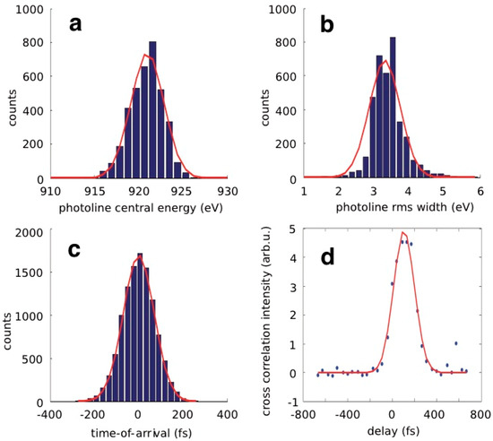
Figure 8.
Measured XFEL parameters. (a) Single-shot distribution of central XFEL photon energy, measured with the magnetic bottle electron spectrometer (MBES); (b) Single-shot distribution of XFEL photon energy spread (rms); (c) Distribution of relative arrival time between NIR laser and XFEL, measured for a nominal delay set to zero (at full temporal overlap); (d) Cross-correlation intensity scan, by moving the NIR pulse in small steps through temporal overlap with the X-rays pulse and incorporating the arrival time jitter (Blue bars and points are the experimental data, and red full curves are fits to the data).
For the streaking experiment one has to carefully overlap the XFEL pulse with the NIR laser spatially and temporally. A fine-scan was performed by integrating the electron detection signal in an energy region close to the unstreaked photoline and changing the length of the path of the optical laser in small steps (compare Figure 9 for the measurement principle). The better the XFEL and the NIR laser are overlapped, the more electrons see the NIR field and the detected electron spectrum deviates from a pure photoline. Thus, one gets a time-dependent measure of the strength of the overlap. This signal can be used to find the maximum temporal overlap (see Figure 8d).
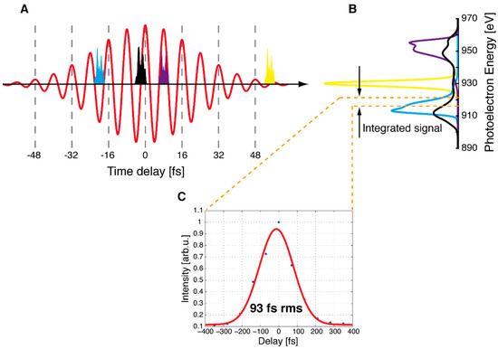
Figure 9.
Determination of XFEL–NIR arrival time jitter. Panels (A,B) show the simulation of X-ray pulses (blue, black, purple and yellow) overlapping with the NIR streaking field (red) at different relative delays and the corresponding photoelectron spectra. Panel (C) depicts the measured cross-correlation obtained by integrating the signal over a small region of the spectrum at a point 4σ away from the unstreaked photoline for different delay settings. In the case of very poor overlap (the situation depicted as the yellow XFEL pulse in panel (A) there is nearly no streaking effect: the measured photoline stays narrow and the signal in the region of interest is small. As the X-ray pulse overlaps more and more with a vector potential of higher amplitude (the cases of the blue, purple and black pulse, in ascending order of streaking potential amplitude), the generated PE spectra become ever more broadened and the integrated signal rises accordingly. Therefore, the detected width of this cross-correlation can be interpreted as the convolution of the NIR pulse duration and the average arrival time jitter between the XFEL and the streaking field (panel (C)), which amounts to ~93 fs rms in our case (Figure from [96]).
Direct time-domain measurement of ultrashort X-ray pulses
In this experiment [69], the attosecond streaking technique was applied to X-ray FEL pulses for the first time. The XFEL and the streaking laser typically are two separate laser sources and need to be externally synchronized to keep them temporally overlapped. Nevertheless, even with synchronization a residual shot-to-shot arrival time jitter between the two lasers remains. Since the arrival time jitter between XFEL and NIR is of the same order as the NIR pulse duration, it is not possible to assign a definite delay and corresponding value of the vector potential with respect to the streaking field to each single XFEL pulse. With the presented scheme and following analysis one can overcome the synchronization issue and derive an upper limit of the X-ray pulse duration for each single shot in a manner that is decoupled from all machine parameters and can be used simultaneously with any ongoing measurement.
Before presenting the details of the evaluation, it is an important prerequisite for the following analysis to make an estimate of the X-ray pulse duration compared to the streaking laser period. Following the previous reasoning, for longer X-ray pulses (enclosing one or more cycles of the streaking field) the energy shift of the streaked photoelectron spectrum is negligible, thereby resulting in uniformly larger streaked spectral widths. This is evident when looking at the spectra presented in Figure 10a,d, which show 50 simulated (a) and measured (d) streaked spectra obtained with X-ray pulses stretched to around 25 fs (by changing the compression of the electron bunch) and a streaking field with a wavelength of 2 μm. For the X-ray pulses at optimized compression and inserting the spoiler [32], one can see in Figure 10b,e that when employing the same 2 μm streaking laser, the situation is globally unchanged, whereas when using a 2.4 μm wavelength NIR laser, one observes the apparition of a clear streaking regime [21,66] (Figure 10c,f). This is clear evidence that the XFEL pulses under these experimental conditions are at least shorter than 8 fs (one period at 2.4 μm wavelength) and one can apply the streaking concept for the X-ray pulse duration acquisition.
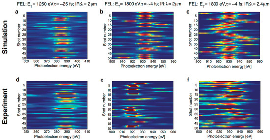
Figure 10.
Streaked X-ray photoelectron spectra (top: Simulation, bottom: Experiment). Six color-coded intensity plots for photoelectron spectra of 50 consecutive shots, for two different X-ray pulse durations (τX−ray ≈ 25 fs and τX−ray ≈ 4 fs) streaked by optical lasers with two different central wavelengths (λ = 2 μm and λ = 2.4 μm). Panels (a–c) are simulations, while (d–f) are constructed from the corresponding measurements taken at the LCLS during our experiment. The long 25 fs X-ray pulses (panels (a,d)) exhibit nearly no spectral shift but rather uniform smearing of the photoelectron (PE) spectra, revealing that for these long pulses the measurement method breaks down. A similar behavior can also be observed for the short X-ray pulses (<5 fs) when streaked with the 2 μm NIR field, shown in the middle in panels (b,e): the ratio of the period of one optical cycle at this wavelength to the X-ray pulse duration is still not optimal, resulting in a high probability to find the spectral center near the unstreaked value. In contrast, for the 2.4 μm streaking field, right panels (c,f), the whole spectrum is hugely shifted away from the mean, as is expected when the PEs ‘see’ only part of the NIR vector potential, a clear demonstration of the onset of the streaking regime. Note that the overall shift of the central energy in panels (e,f) from 930 eV to 920 eV is due to an accordingly lower X-ray photon energy (1790 eV instead of 1800 eV) for this measurement and is not a streaking effect. (Figure from [96]).
Single-shot X-ray pulse duration measurement
As described above, one of the major challenges for these types of correlation measurements is the arrival time jitter of each single XFEL pulse with respect to the NIR laser (see Figure 9). Due to the statistical nature of the SASE process the actual pulse shape and thus the duration of consecutive XFEL pulses also varies from shot to shot, necessitating a single-shot measurement technique for its determination. That means that one has to adopt a different method to extract the X-ray pulse duration from the measured spectra than what is conventionally used in streaking experiments with precisely synchronized gas-phase high harmonic sources.
As the relative phase between the X-ray pulse and the streaking field is not known a priori, one has, in a first step, to determine the value of the streaking vector potential for each single XFEL pulse. This fact is critical for the analysis and restricts the characterization to the determination of upper limits for the X-ray pulse durations. The peak of each single-shot spectrum that is pushed farthest away from the unstreaked center is identified and is assumed to stem from an overlap of the X-ray pulse with a local maximum of the vector potential. This sets an experimental limit for the local electric field strength of the streaking laser for each specific X-ray shot and thus for the gradient of the vector potential, which will be underestimated on average.
In the second step of the evaluation process one uses this vector potential as a calibration factor to convert the measured spectral width of each streaked photoelectron wave packet into an upper limit for the duration of the corresponding X-ray pulse.
To illustrate the principle of evaluation, have a look at an example from the data, sketched in blue in Figure 11a. In this case a streaked spectrum ranging from 915 eV to 945 eV was measured, corresponding to a width of the streaked spectrum of δs = 30 eV and a maximal energy shift in relation to the unstreaked photoline at 920 eV of ∆ε = (945 − 920) eV = 25 eV. Following Ref. [99], one assumes the vector potential ANIR(t) of the streaking field to be approximately linear in time,
with a slope given by the peak electric field Epeak = E(tpeak) of the half-cycle that the photoelectrons are overlapping with, which occurs at the moment tpeak. The period of the streaking laser was tperiod = 8 fs, setting the time interval for the vector potential to rise from a zero-crossing to a maximum (a quarter period) to 8 fs/4 = 2 fs. This value corresponds to the above calculated maximum shift ∆ε = 25 eV in the energy domain. Now one can use the measured width of the streaked spectrum, δs = 30 eV, as a ruler for the pulse length, resulting in an upper limit for the X-ray pulse duration:
which is (30/25) × (8/4) = 2.4 fs in this case, represented by the blue X-ray pulse on the left in Figure 11a.
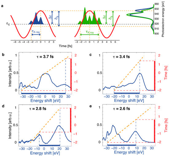
Figure 11.
Streaking of few-femtosecond X-ray pulses. The top panel (a) shows the principle of the X-ray pulse duration evaluation: the maximal shifted peak of the measured PE spectrum is associated with an overlap of the X-ray pulse with a local maximum of the streaking field (blue pulse on the left). This energy shift ∆ε defines the gradient of the energy-to-time conversion and the overall width δs of the streaked spectrum is used for the determination of the XFEL pulse duration. The green X-ray pulse, twice as long and depicted in the middle, gives rise to a very similar PE spectrum, leading to a residual ambiguity of the XFEL pulse length measurement. Panels (b–e) show four different streaked photoelectron spectra as measured in the experiment (solid blue lines) at different values of the NIR vector potential and the respective linear streaking ramp (dashed orange lines) derived from the maximum shifted peak of the spectrum. Corresponding pulse duration upper limits are given and shown on the right vertical axes (red bars) (reproduced with permission from [69], Copyright Nature Publishing Group, 2014).
There is, in addition, a residual ambiguity in the analysis method that has to be considered. Figure 11a shows schematically a second XFEL pulse (green, in the middle) with a different duration that nevertheless leads to nearly the same measured width of the streaked spectrum. Since it was assumed that the X-ray pulse partly overlaps with a local maximum of the vector potential, one cannot discern streaking effects caused by the right or the left edge of this vector potential curve. To get a correct upper limit for the possible X-ray pulse duration, one therefore must double the above calculated value to 4.8 fs. All pulse lengths between 2.4 fs and 4.8 fs are compatible with the measurement.
Figure 11, panels (b)–(e), shows measured streaked photoelectron spectra generated by four different X-ray shots (solid blue curves) and their derived pulse duration upper limits (red bars on the right). From the maximum shifted peak in panel (b) a maximal energy shift ∆ε = |−32| eV is inferred, i.e., the laser half-cycle of 4 fs is mapped onto an energy range of 2 × ∆ε = 64 eV. The complete spectrum spans from −32 eV to 27 eV, setting the overall width to δs = 59 eV and corresponding to a pulse duration of 3.7 fs. In a similar manner one derives upper limits for the other pulse durations of 3.4 fs in panel (c), 2.8 fs in panel (d) and 2.6 fs in panel (e), respectively. Considering the ambiguity of the energy-to-time mapping, all these shots are in principle also compatible with the doubled pulse lengths.
Owing to the statistical nature of the SASE generated XFEL pulses originating from noise, the X-ray pulse profiles differ greatly from shot to shot. For the first time, this variation in the intensity substructure of XFEL pulses can be shown directly in the time domain. In Figure 11b, an XFEL pulse consisting of only one single peak overlaps with the zero crossing of the vector potential and is broadened compared to the photoline. Different arrival times of the XFEL pulse relative to the streaking laser lead to an overall shift of the whole spectrum as depicted in Figure 11c,d, where the XFEL pulse overlaps with the negative or positive part of the vector potential and the resulting spectrum is shifted accordingly. An individual peak followed by a tail (c) can be distinguished from a pulse containing two well-separated spikes (d) or even three individual spikes as shown in Figure 11e.
If one repeats this analysis for each single shot and plots the number of shots versus the corresponding pulse durations, an estimation of the average FWHM X-ray duration can be built up as a histogram (Figure 12). The average pulse duration of the XFEL is best fitted by a Gaussian distribution with a mean value of ~4.5 fs and a standard deviation of 1.7 fs. Clearly, this is a very conservative upper limit and the actual pulse duration is likely to be considerably shorter for the vast majority of LCLS pulses in this mode of operation.
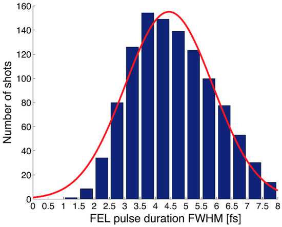
Figure 12.
Average XFEL pulse duration. A histogram of the possible pulse duration values in agreement with the measurement (blue) for the described parameter range at LCLS. The red solid line shows a Gaussian fit to the distribution, indicating an upper limit for the average X-ray pulse duration of ~4.5 fs (reproduced with permission from [69], Copyright Nature Publishing Group, 2014).
Measurement of sub-femtosecond X-ray pulses
Due to pulse-to-pulse fluctuations there are some pulses that are considerably shorter than the average duration. XFEL theory predicts a temporal pulse substructure composed of a train of ultrashort spikes [100] with a typical width corresponding to the coherence time, characterized by the X-ray photon energy bandwidth and machine specific parameters. For the parameter range during the measurements at the LCLS, spike durations of about one femtosecond and even below are expected to occur (compare for example Ref. [48]). The average number of spikes per XFEL pulse can be estimated, but it will also be subject to shot-to-shot variations. Occasionally, an X-ray pulse consisting of just one single isolated spike will occur.
A closer analysis of the data confirms the existence of such ultrashort ‘single-spike’ pulses, constituting about 5% of the total number of shots. By sorting and collating the streaked spectra with just one peak and determining their centers, one can identify the energy shift ∆ε and the spectral width δs for each of these shots. Figure 13 shows the measurement principle for attosecond X-ray pulses: For the evaluation of these single-spike pulses one assumes that due to simple statistical considerations the predominant number of XFEL shots overlaps with a part of the ramp of the vector potential and hence again Equation (2) is valid in most cases. Then one can employ a reasoning similar to that described above to assess an upper limit for the pulse duration. In order to not overestimate the actual value of the vector potential for the conversion into the time domain, the minimum possible value of the vector potential compatible with each specific shot is used for the analysis, that is the value that corresponds to the observed shift of the central photoelectron energy for each of these single-spike pulses. This is a very conservative approach and will again result in the determination of an upper limit for the respective pulse duration.
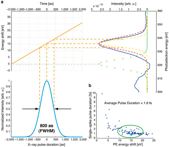
Figure 13.
Measurement of an attosecond X-ray pulse. Panel (a) on the right-hand side shows a measured spectrum of a single XFEL intensity spike (solid dark blue line) and the corresponding Gaussian fit (dashed red line). The shift of the peak from the unstreaked central energy at 920 eV (green dotted line) defines the energy-to-time ramp (top left), with the help of which the width of the deconvoluted spectrum (yellow dashed-dotted line) can be converted into a pulse duration upper limit of 800 as, depicted as the light blue line on the bottom left. Panel (b) at the bottom right shows the derived upper limits for the pulse duration of all single-spike shots as a function of the spectral energy shift of the peak. The very short pulse described in panel (a) is marked as the bigger light blue dot. The outliers towards longer pulse durations are all associated with small energy shifts (≤5 eV), and therefore potentially stemming from an underestimation of the actual streaking vector potential by our method. Nevertheless, most of the measured single-spike X-ray pulse durations are in the range of 1.5 femtoseconds and below, highlighted by the green oval (reproduced with permission from [69], Copyright Nature Publishing Group, 2014).
For the shot marked as the bigger light blue dot in panel b in Figure 13, the energy shift amounts to ∆ε = 17.4 eV. Following deconvolution of the initial unstreaked X-ray photon energy bandwidth, which was determined by separate measurements, from the measured signal and using ∆ε as a calibration factor the spectral bandwidth of this single peak was found to correspond to an X-ray pulse with a duration of maximum 800 attoseconds FWHM. In general, the derived upper limits for the duration of X-ray single-spike pulses are mainly in a range of 750 as to 1500 as (FWHM) (marked by the green oval in Figure 13b), which is in good agreement with the predictions based on equations for the SASE process under the conditions of the LCLS machine parameters [48]. However, in case the X-ray shot is actually overlapping with a maximum of the vector potential, this method breaks down; therefore, novel streaking concepts have to be developed for the unambiguous and complete characterization of X-ray FELs, as presented in Section 3.1.2 for femtosecond pulse structures, and in the outlook (Section 4) for the determination of the full time–energy information of SASE X-ray pulses with attosecond resolution.
3.1.2. Laser-Driven Terahertz Streaking for Complete Temporal Characterization
Single-cycle terahertz streaking at XFELs
In contrast to attosecond HHG sources, at SASE XFELs the temporal profile and arrival time of the X-ray pulse changes from shot to shot and cumulative measurements are typically not possible. Therefore, the pulse measurements should be performed on a single-shot basis. In addition, the duration of SASE FEL pulses can be as long as 100 femtoseconds. As a result, lower frequency streaking fields, in the THz regime, are required (1 THz corresponds to a half-cycle time of 500 fs) as the ionizing FEL pulse must be shorter than a half-cycle of the streaking field.
While phase-locked THz pulses do not typically exist at XFEL facilities, at FLASH it is possible to send the “spent” FEL-driving electron bunch through an additional dedicated undulator to generate multi-cycle, phase-stable THz pulses. In principle, this allows for direct application of attosecond techniques. Indeed, in previous work, this THz source was used as the streaking field for temporal characterization of the XUV FEL pulses [101]. However, this technique does not provide access to relative timing information for pump–probe experiments. Furthermore, the THz streaking field changes as the electron beam is varied, fluctuates or is tuned, influencing the measurement and effectively limiting the utility of this technique. In an extreme case, when the accelerator is tuned for the shortest FEL pulses using low-charge highly compressed bunches, the beam-based generated THz might not even be strong enough for streaking.
An independent laser-driven THz source for pulse characterization overcomes the limitations of streaking with accelerator-based THz sources, while maintaining the capability to characterize 100 fs long pulses. In addition, as laser-driven THz fields are locked to the external laser, the streaking measurement provides the capability to determine simultaneously the FEL pulse arrival time and its pulse profile on a time base that is synchronized to the pump–probe experiment environment.
Many laser-based THz sources rely on optical rectification of femtosecond Ti:sapphire laser pulses in a LiNbO3 crystal [102]. With this technique, high-field phase-stable single-cycle THz pulses with pulse durations of ~2 ps can be generated. The THz vector potential, which is the relevant quantity in streaking spectroscopy, has a half-cycle of ~600 fs. The half-cycle duration, or streaking ramp gives the dynamic range of the measurement. Notably, it is significantly longer than the maximum expected FEL pulse duration and facility timing jitter. Therefore, once the temporal overlap between the X-ray pulse and the THz pulse has been established, all subsequent FEL pulses will overlap at some point on the single-valued streaking ramp allowing them to be characterized unambiguously.
The principle of a single-cycle THz streaking measurement is illustrated in Figure 14. Three characteristic measurement conditions are shown in the figure. In the first panel the FEL and THz pulses are not temporally overlapped, therefore, the photoelectron spectrum remains unperturbed and only the FEL pulse spectrum shifted by the ionizing potential of the target gas is measured. In the second panel the FEL pulse is overlapped with an extremum of the vector potential (it overlaps with the bottom of the streaking ramp), resulting in a maximally downshifted photoelectron spectrum with minimized spectral broadening. Consequently, the temporal structure of the pulse is not observed in the measured spectrum. In the last panel, the ionizing FEL pulse coincides with a zero crossing of the THz vector potential . Photoelectrons emitted by the leading and trailing edges of the FEL pulse are streaked with a momentum shift of opposite sign, resulting in a maximally broadened photoelectron around the field-free central energy. At this temporal overlap, the arrival time as well as the temporal profile and duration of the FEL pulse can be accessed with highest resolution.

Figure 14.
Schematic of FEL pulse characterization by THz streaking. Three distinct measurements are depicted in frames (a–c). FEL induced photoemission from a noble gas, which replicates the FEL temporal profile (black filled area), is broadened and shifted, or “streaked”, depending on the instant of overlap with the THz pulse. The THz streaking pulse electric field is shown in blue, while the corresponding vector potential is drawn in red in all three panels. On the right vertical axis, the resulting kinetic energy of the photoelectrons is indicated: in black the field-free spectrum, defined by the SASE FEL bandwidth in the unstreaked case (a), and in gray spectra for the streaked cases, at overlap with an extremum (b) or at the zero-crossing (c) of the THz vector potential. In (c), overlap occurs near the zero-crossing of the THz vector potential where the arrival time and temporal profile can be accessed with the highest resolution (reproduced with permission from [103], Copyright Nature Publishing Group, 2012).
If the streaked photoelectron spectrum is significantly broader than the initial bandwidth of the ionizing FEL pulse, the temporal profile of the FEL pulse can be recovered directly from the measured spectrum. In this case, also referred to as the strong streaking regime, the energy gradient that is imprinted onto the electron wavepacket by the streaking field is much larger than the initial energy variation caused by an FEL pulse with an initial energy chirp. As a result, the degree of spectral broadening is assumed to depend only on the duration of the FEL pulse and the gradient of the THz streaking field.
To make a calibrated transformation from the streaked photoelectron spectra to the time domain, the THz vector potential must be known. Due to timing jitter at FELs, the vector potential cannot typically be determined directly from the streaking spectrogram as is the case in attosecond spectroscopy. Rather, at XFELs the transformation map is determined in a two-step process. First, the electric field shape is evaluated independently by electro-optic-sampling. Second, the electric field is scaled by evaluating a distribution of streaking measurements over all possible time delays. Measurements that overlap with a maximum of the vector potential result in maximal kinetic energy shift, as depicted in Figure 14, panel b. The maximum kinetic energy shift can then be inverted to determine the absolute THz electric field strength:
Here, λL is the streaking laser wavelength, E0 is the maximum electric field, Wi is the initial electron energy and c is the velocity of light in vacuum. With the transformation map and under the assumptions listed above, the temporal profile of the FEL pulse can be retrieved from a single-shot streaked spectrum as illustrated in Figure 15.
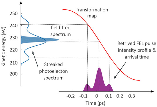
Figure 15.
Mapping THz streaked spectrum to temporal profile. When the streaked photoelectron spectrum (blue line) is significantly broader than the initial spectral bandwidth of the FEL photon pulse (blue filled area), the temporal profile (violet filled area) of the ionizing FEL pulse can be easily retrieved. The red curve indicates the streaking vector potential used as a transformation map, to obtain temporal information from a measurement in the spectral domain. (Figure from [95]).
THz streaking can be used to simultaneously determine the arrival time of the FEL pulse. But, it is important to note that the information provided by this diagnostic is far more complete than a simple arrival time. In fact, the FEL pulse profile is given on a time-base defined by the THz streak ramp that is locked to the experiment environment, if the same femtosecond laser pulse that is used the generate the THz streaking pulse is also used to pump dynamics in an independent experiment. With this complete information, it is possible to define a single point as the “arrival time”. This point could be given by the center-of-mass of the FEL pulse, or the position of the peak intensity of the FEL pulse, or at a certain intensity threshold. The exact definition would depend on the dynamics being observed, but crucially, any definition can be chosen when the pulse is characterized on an experimentally relevant time base.
For FEL pulses with a broad initial bandwidth and large initial energy variation across the pulse, it may not be possible to neglect the initial chirp in these streaking measurements. Moreover, it may be crucial for experimental applications to characterize the spectral chirp in the FEL pulse.
For linearly chirped FEL pulses, at least two measurements of the streaked photoelectron spectrum at opposite slopes of the vector potential are required to infer the temporal duration and shape of the ionizing pulse [104]. At FELs, different experimental approaches can be taken to achieve this on a single shot basis. For example, two time-of-flight detectors, both mounted in the plane of the streaking field polarization but in opposite directions could be used to record two spectra with opposite slope. Alternatively, it has been proposed that different phases of the streaking pulse can be realized by taking advantage of the Gouy phase shift, which occurs when a Gaussian beam propagates through a focus [105].
If single-shot information cannot be obtained, information regarding the average chirp of the FEL pulses could be obtained by making two sets of measurements with THz pulses generated with two distinctly different phases. This can be realized easily for certain THz generation methods. In particular, for THz pulses generated using collinear rectification in ZnTe or organic crystals with higher electro-optic coefficients.
Measurement resolution
The temporal resolution in THz streaking of X-ray pulses depends primarily on the energy resolution of the photoelectron spectrometer and the THz streaking strength. In addition, the initial FEL pulse bandwidth and the evolution and Gouy phase advance of the THz pulse in the interaction region can also limit the temporal resolution. Moreover, shot-to-shot intensity fluctuation of the streaking pulse, as well as energy jitter in the FEL pulse can degrade the temporal resolution of the measurement.
Typically, the streaked photoelectron spectrum is recorded with a time-of-flight (TOF) spectrometer. The energy of the photoelectron is determined by measuring the time t required by the electron to travel from the interaction region to the detector placed at a known distance L. The kinetic energy of the electron is given by:
From this simple kinematic equation, a measure of the energy resolution can be written:
where ∆t is the smallest interval that can be resolved by the electronic detection system.
The acceptance angle of the TOF spectrometer is defined by its geometry (length of the drift tube and detector diameter). In order to enhance the sensitivity, the TOF is equipped with an electrostatic lens at the entrance of the drift tube, which increases the effective acceptance angle for electrons within a specific kinetic energy range. Additionally, a post acceleration stage in the TOF ensures a flat response of the electron detector (multi-channel plate, MCP) regardless of the initial electrons’ kinetic energy. Wide acceptance angle, and flat detector response is especially important for measurements at FELs, as the full spectrum of photoelectrons must be collected in a single shot. High efficiency through a larger acceptance angle is usually accompanied by a decrease of the energy resolution due to variations in the electron flight path for electrons of same energy, but with different initial momentum. Moreover, the need to collect single-shot spectra, means that many photoelectrons must be generated during each exposure which can lead to space charge and additional degradation of the energy resolution.
Beyond these fundamental factors, the relationship written above for indicates that the energy resolution of the TOF is limited by the length of the drift tube and the temporal resolution of the detection electronics. The latter one includes the response time of the MCP electron detector and the resolution of the analog-to-digital (ADC) converter [106]. To improve the energy resolution, retardation potentials can be applied to increase the flight time of the electrons, before they enter the drift tube.
At FELs, the relative energy resolution of electron TOF spectrometers is usually not much better than ~1%. The dominant issue lies in the temporal resolution of the detection electronics for multiple photoelectron acquisition.
The issue is illustrated in Figure 16. In the first panel, the signal resulting from a single electron response is illustrated. The single electron response is amplified and a pulse with a characteristic duration determined by the capacitive properties of the MCP amplifier is produced. For a TOF operating in a single-electron mode, it is sufficient to determine the time-of-flight from the rising edge of this signal, which can be determined with high accuracy, depending mostly on the temporal resolution of the ADC that samples the pulse. In panel b, the MCP response for multiple distinct single-electron events are depicted. This situation is typical in the case of experiments at synchrotrons, where, on average, less than one electron per X-ray shot is detected. The accumulated arrival time distribution of the single photoelectron events gives the photoelectron spectrum. The time resolution is mostly determined by the rise time of the MCP signal and the resolution of the digitizer.

Figure 16.
Time-of-flight (TOF) Energy resolution at FELs. In contrast to application at synchrotrons, the resolution in time-of-flight spectra collected at XFELs is dependent on the single electron response of the detector. Panel (a) depicts the single-electron response; panel (b) shows multiple electron hits; panel (c) shows the effective resolution, if the multiple electron hits are accumulated within a single-shot acquisition or a cumulative acquisition. At XFELs, the acquisition is single-shot and the observed signal is a convolution of the photoelectron bandwidth with the single-electron response. If the acquisition is cumulative, the observed signal is the convolution of the photoelectron bandwidth and the resolution with which the edge of the single-electron signal can be determined. (Figure from [95]).
In contrast, in measurements at FELs, where the entire photoelectron spectrum must be recorded in one FEL shot, the sum of the individual electron signals is collected and the detector acts as a current amplifier, rather than a discriminator for counting single-electron events. The measured photoelectron spectrum is then a convolution of the actual signal and the width of the single-electron signal. Therefore, to increase the resolution of single-shot TOF measurements, the pulse width of a single-electron event must be reduced. To achieve this, MCP amplifiers with a smaller diameter can be used; however, this would reduce the collection efficiency.
Independent of TOF detector issues, the THz streaking strength determines the degree of broadening of the photoelectron spectra and thus directly influences the achievable temporal resolution. The FEL pulse can be retrieved with the highest resolution, if it is overlapped at the zero crossing of the streaking pulse vector potential. At this overlap, the maximum streaking strength is present and given by [101]:
The average streaking speed is given by the ratio of the peak-to-peak amplitude of the kinetic energy shift to the rise time of the streaking vector potential:
With these formulas, a measure of the temporal resolution of the streaking measurement can be written as:
where is the width of the photoelectron spectrum without streaking field.
Clearly, the temporal resolution can be increased by applying steeper streaking fields. Such fields can be achieved by scaling the THz generation to higher peak intensities, or alternatively by using higher frequency THz pulses with shorter streaking ramps.
Experimental implementation
Proof-of-principle experiments on THz streaking were first performed at the free-electron laser FLASH in Hamburg. This facility operates in the XUV spectral range emitting pulses with ~100 femtosecond duration and below. Typical pulse energies are on the order of 100 µJ. The experimental setup is shown in Figure 17.
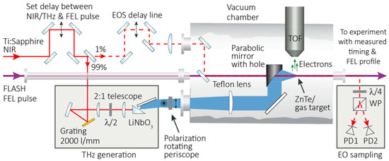
Figure 17.
THz streaking apparatus. Layout of the THz streaking experimental setup used at FLASH: The NIR laser pulse is split into two parts. Most of the pulse energy is used for the tilted pulse-front THz generation in LiNbO3, in setup geometry as shown. The remaining 1% pulse energy is used as a probe for electro-optic sampling (EOS) of the THz pulses in a 500 μm thick zinc telluride (ZnTe) crystal. The NIR probe pulse and the FEL pulse pass through a 2 mm hole in the parabolic mirror and are collinearly overlapped with the THz beam and focused into the interaction region, which is fixed by the position of the time-of-flight spectrometer. For the EO-sampling a ZnTe crystal is placed in the exact interaction region. The crystal is also used as an observation screen for monitoring the spatial overlap of the FEL and the NIR probe pulses. For the streaking measurement a gas nozzle providing neon or helium is placed in the interaction region. The FEL pulses eject a burst of photoelectrons from the atomic gas system and the kinetic energy of the photoelectrons is modified by the THz pulse. Recording the photoelectron spectrum with the TOF spectrometer consequently enables characterization of the FEL pulse (reproduced with permission from [103], Copyright Nature Publishing Group, 2012).
THz pulses were generated with user pump–probe laser, ~3 mJ, 60 fs pulses from a Ti:sapphire laser amplifier by tilted pulse front optical rectification in LiNbO3. The peak on-target electric field strength was observed to be 165 kV/cm. The THz electric-field shape was characterized independently by electro-optic sampling, and the absolute field strength determined from a distribution of streaking measurements as discussed before. The THz electric field is shown in Figure 18, panel (a).

Figure 18.
Proof-of-principle streaking measurement at FLASH. (a) The single-cycle THz electric field. (b) Single-shot spectrogram composed of 12,000 consecutive shots. (c) The averaged spectrogram, with approximately 400 shots binned at each 100-femtosecond time step. The duration of the THz streaking ramp is indicated by the dashed white lines in the right panel, giving the dynamic range of the measurement, which is ~600 fs. (Figure from [95]).
Single-shot streaking measurements on XUV pulses at ~260 eV photon energy were made in helium. The corresponding single-shot and averaged THz streaking spectrograms are shown in Figure 18, panels (b) and (c), respectively. To build the spectrogram, the delay between the THz and the soft X-ray pulses was scanned in 100 fs steps. Approximately 400 single-shot spectra were averaged at each time delay to generate the averaged spectrogram. For large delays, where the THz field is weak, the He 1s photoemission peak is nearly unaffected and located near its field-free energy. Close to temporal overlap the kinetic energy of the photoelectrons is shifted and broadened depending on the THz streaking field phase. In the averaged spectrogram the dynamic range given by the single valued THz streaking ramp is indicated with dashed white lines. As the streaking ramp of ~600 fs is significantly longer than the maximum expected FEL pulse duration and timing jitter, once the streaking THz pulse and the FEL are temporally overlapped, all single-shot acquisitions will occur on a uniquely defined position on the streaking ramp.
A characteristic single-shot measurement reproduced from reference [103] is shown in Figure 19. The streaked spectrum is shown in panel a. The retrieved temporal profile, with conversion map as a dashed line, is shown in panel b. The statistical error in the single-shot spectrum is calculated according to the number of electrons collected within the energy resolution window of the detector. As the photoelectron spectrum is heavily oversampled, boxcar integration is performed across the spectrum, resulting in a smooth error envelope that bounds the measured spectrum. The reconstructed FEL pulse exhibits a dominant central feature with a width of (53 ± 5) fs FWHM and has weaker satellite features at approximately 100 fs from the main peak.
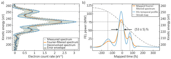
Figure 19.
Single-shot FEL pulse profile. (a) Example of a measured streaked photoelectron spectrum. The shaded error envelope is calculated by boxcar integration, based on the number of electrons collected within the TOF energy resolution window of the time-of-flight spectrometer. The blue dots are raw data points in the measured streaked spectra. Orange curve shows the spectra after Fourier filtering to remove high-frequency noise. Blue curves are filtered, streaked spectra following deconvolution of the photoelectron spectrometer resolution. (b) Retrieved temporal profile for this FEL shot. Orange and blue curves are the mapped intensity structures corresponding to the Fourier-filtered spectrum and the deconvolved spectrum in panel (a), respectively. The energy-to-time conversion map is depicted as the dashed gray line in panel (b), with the corresponding energy axis on the right (reproduced with permission from [103], Copyright Nature Publishing Group, 2012).
The temporal profile shown in Figure 19 is given on a time base that is locked to the laser that generates the streaking THz pulse. This information can be condensed into a single arrival timestamp by calculating the center-of-mass of the retrieved FEL pulse profile. To evaluate the short-term timing jitter at FLASH ~450 consecutive FEL pulses, collected near time-zero were analyzed. The results are displayed in Figure 20. The shot-to-shot analysis is shown in panel (a), and the distribution of arrival times, which is the timing jitter, is shown in panel (b).
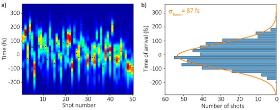
Figure 20.
Arrival time and jitter. Panel (a), false color plot of 50 consecutive single-shot measurements recorded close to time zero. The center of mass of the individual photoelectron spectra (black dots) is used to determine the arrival time of each pulse. Panel (b) shows the distribution of arrival times collected over ~450 consecutive shots with a Gaussian fit. The corresponding width of the fit is ~87 fs rms, which is a measure of the short-term timing jitter between the pump–probe laser that generates the THz, and the FEL (reproduced with permission from [103], Copyright Nature Publishing Group, 2012).
The Gaussian fit to the distribution has a width 87 fs rms, which is a measure of the short-term timing jitter between the FEL and the pump–probe laser. This value is consistent with the expected performance of the electronic laser synchronization [83]. The accuracy of the relative arrival time information is mainly influenced by the stability of the mean FEL photon energy. During our measurements, it fluctuated with a level of 1 eV rms, which corresponds to a time-of-arrival uncertainty of ~6 fs rms.
THz generation in LiNbO3 is attractive, as the rise time of the streaking field is ~600 fs, resulting in a dynamic range that allows for measurement of all pulses, with lengths that can exceed 100 fs in duration. But the streaking power is limited. Alternatively, THz streaking fields can be generated by collinear optical rectification of infrared laser pulses in the organic electro-optic salt 4-N,N-dimethylamino-4′-N′-methyl-stilbazolium tosylate (DAST). THz fields generated in the DAST crystal have steeper half-cycle rise-times of ~180 fs, which in principle can lead to higher resolution measurements.
At LCLS measurements on 1.1 keV soft X-rays were made using THz pulses generated in DAST. High field strengths approaching 1 MV/cm were observed in the interaction region. However, these measurements suffered from timing jitter due to the reduced dynamic range. The timing jitter between XFEL and THz was measured at ~200 fs rms. Therefore, an additional method for sorting the arrival time of the X-ray pulses with respect to the THz pulses was required to isolate shots that arrived on the single-valued THz streaking ramp [107].
Three streaking spectrograms collected as the relative delay between DAST-THz pulse and X-ray pulse was smoothly varied are shown in Figure 21. The panel on the left shows the single-shot measurements in the order as they were collected and the panel in the center shows the single-shot spectra re-ordered according to the additional timing information from the spectral encoding measurements. In the sorted spectrogram, the shots arriving on the single-valued streaking ramp are clearly identified, allowing for calibrated transformation from streaked kinetic energy to time. The panel on the right shows the measured spectrogram after rotating the DAST crystal by 180 degrees to reverse the sign of the streaking field. In principle, as in attosecond spectroscopy and discussed earlier, this provides access to the average spectral phase, or chirp, of the X-ray pulse in addition to the temporal profile.

Figure 21.
Streaking measurement made with THz fields generated in DAST at the LCLS. (a) In the panel, the single-shot measurements are displayed in the order that they were collected. (b) The single-shot measurements are sorted based on the X-ray pulse arrival time measured by spectral encoding. (c) The panel shows the sorted and binned spectrogram collected with the opposite sign THz field, providing access to the spectral phase.
The streaking power (Equation (7)) in the DAST measurements was ~1.7 fs/eV. With 1% relative energy resolution in the measured photoelectron spectrum, these fields have the potential to be used to achieve ~5 fs resolution in the X-ray profile measurements.
For higher time resolution, to measure pulses compressed to several femtoseconds in duration and shorter to the sub-femtosecond, attosecond regime the wavelength of the streaking fields needs to be decreased further. In attosecond physics, ~10 attosecond resolution is routinely achieved using near infrared streaking fields. However, these fields provide dynamic range of only ~1.5 fs and are only suitable for attosecond pulse characterization.
3.2. Terahertz Streaking with Hard X-rays
Issues at high photon energies
THz streaking with hard X-rays should, theoretically, be easier to achieve than streaking with soft X-rays or HHG sources for a given ponderomotive potential , where is the angular frequency of the streaking field. The energy shift term of Equation (4) predicting the maximum THz streaking effect, , shows that the energy shift increases as the square root of the electron kinetic energy after photoionization Wi. Thus, the streaking effect is indeed stronger and more pronounced, but the difficulties in streaking with hard X-rays come from different sources.
Hard X-rays, especially those over 5 keV photon energy, tend to be fairly non-interactive with most materials. The photoionization cross sections for most elements and molecules drop by orders of magnitude when compared to soft X-rays [108], and make the observation of any kind of photoelectron spectrum on a single-shot basis difficult. Since most FELs that can generate high-energy X-ray radiation tend to have shot-to-shot temporal jitter, and THz streaking is used as a diagnostic to measure that jitter, this difficulty has to be overcome, and there must be enough signal generated in a single shot to measure the temporal properties of the FEL beam. Simply ramping up the gas pressure in the interaction region to get more signal is also not an option, since the TOF spectrometers used for THz streaking measurements have MCPs as their detectors, and they tend to begin malfunctioning if the background pressure of the vacuum chamber becomes too high. Last, but not least, the choice of observable photoionization lines is very limited for hard X-rays, and the large streaking effect heavily influences the settings on the TOF spectrometers themselves. Yet, the experience with the Photon Arrival and Length Monitor (PALM) at the beamtimes performed at the SACLA FEL [12] have conclusively shown that these challenges can be overcome.
Solutions and experience
The experiments performed with hard X-ray streaking at FELs have used photon energies as high as 10 keV [109,110], and had the challenge of performing the streaking measurements for single FEL pulses. The experiment was performed at SACLA, which works at a repetition rate of 30 Hz and pulse energies between 150 µJ and 300 µJ. The choice of a gaseous target with suitable electron binding energies at 10 keV photon energy is limited, and the closest easily reachable noble gas absorption edge is that of the xenon L shell. In this particular case, the Xe 2p3/2 photoionization line was the best suited for the measurements, as it had the largest cross section at this photon energy, and xenon was easily available for the experiment.
To ensure that the number of photoelectrons generated by the ionization process was as large as possible, while keeping the mean background pressure in the vacuum chamber low enough for safe MCP operation at the same time, the experimental setup used pulsed piezo valves [111] that were synchronized to the FEL trigger signal and allowed short 15 µs (FWHM) bursts of xenon gas into the chamber very close to the interaction region. A large 1200 L/s pump was placed directly below the gas jet to suck away the particles as quickly as possible and additional differential pumping was installed for the TOFs. The valve was backed by xenon gas at a pressure between 2 bar and 3 bar above atmosphere and was equipped with a conical nozzle with a 150 µm exit diameter, which forced the gas atoms to cluster upon entering the chamber. This arrangement both increased the local density of the atoms at the point of photoionization due to the formation of large, thousand-strong Xe clusters, and prevented a large broadening of the gas jet as it streamed from the nozzle into the vacuum [112]. Overall, the choice of xenon gas as the interaction medium together with the specific nozzle type ensured that there was sufficient signal for single-shot measurements even at 10 keV, and worked well even when the intensity of the X-rays was reduced by introducing a monochromator into the beam path. Moreover, a non-streaked TOF photoionization measurement was implemented upstream of the THz streaking region, since both the bandwidth and the photon energy of FEL pulses change from shot to shot. The availability of a calibration measurement for every shot makes the evaluation of the single-shot arrival time jitter and the temporal characteristics of FEL pulses much easier.
Because the kinetic energy of electrons set free at 10 keV X-ray photon energy amounts to about 5200 eV for the Xe 2p3/2 shell, the streaking shift in electron momentum according to Equation (1) is much larger than that experienced with soft X-rays, even when fairly weak THz fields are applied. In the experiments performed in [109,110], the electric field strength of the focused THz beam in the interaction region was only between 5 MV/m and 6 MV/m, but the maximum streaking energy shift observed was about 100 eV. To accommodate this large shift, the TOFs had to be designed to be able to detect electrons over a large energy window with constant resolution over the whole range and special care had to be taken to not accidentally cut off any signal by choosing the retardation potentials on the TOFs too high. For example, though the kinetic energies of streaked photoelectrons shifted by ±100 eV lie between 5100 eV and 5300 eV in this case, the retardation potentials were set to an upper limit of about 4850 V to ensure that no signal was lost and the spectral resolution was not compromised due to contributions from the full FEL bandwidth or dispersive focusing effects of the TOF.
In addition to these special components, the setup also included the standard components for a THz streak camera. A parabolic mirror with a centered hole inside the vacuum chamber focused the collimated THz beam collinearly with the FEL propagation direction onto the streaking interaction region. The schematic setup of the experiment from [110] is shown in Figure 22.
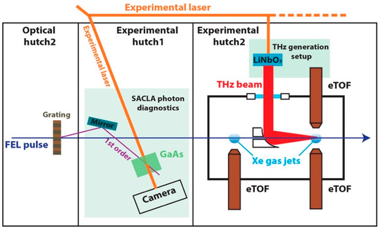
Figure 22.
THz streak camera setup for experiments in [110] (reproduced with permission from [110], Copyright Optical Society, 2017).
The experiment conducted in [110] compared the arrival time measurements of the spatial-encoding SACLA timing tool and the PALM, finding that the two agreed to within about 17 fs of each other at 9 keV photon energy. Earlier measurements presented in [109] showed a better arrival time agreement, which can be explained by the altered geometry for the PALM in [109]. The entrance opening to the TOF was twice as far away from the interaction region than ideal due to a manufacturing issue with the PALM chamber, which affected the number of electrons that were detected. This in turn caused the peaks to be less well-defined and reduced the accuracy of the measurement accordingly. The measurements are presented in Figure 23.
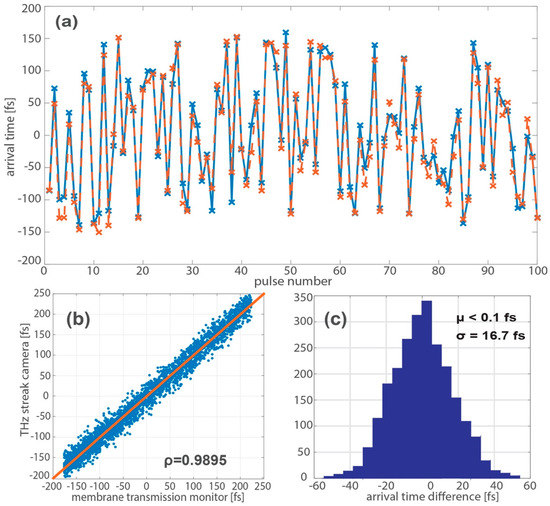
Figure 23.
Comparison of the spatial-encoding timing tool with the Photon Arrival and Length Monitor (PALM) at SPring-8 angstrom compact free-electron laser (SACLA) (reproduced with permission from [110], Copyright Optical Society, 2017). (a) compares the SACLA timing tool (blue solid line) and the PALM (red dashed line) arrival time measurements for a set of consecutive pulses; (b) shows the correlation ρ between the two methods for several thousand shots; (c) shows the histogram of the deviations between the two methods from (b).
To demonstrate the flexibility of the PALM, two-color mode measurements at SACLA showed that the PALM could also measure the temporal separation of multiple FEL pulses. In this mode, the FEL was set to create two FEL pulses at photon energies of 9 keV and 8.8 keV, with the ability to shift their relative arrival times with respect to each other by manipulating the X-ray generating electron beam with the help of a magnetic chicane. The average rms jitter of the two pulses with respect to each other at a given delay setting was about 31 fs, of which about 17 fs are attributed to the uncertainty of the PALM measurements. These results are presented in Figure 24.
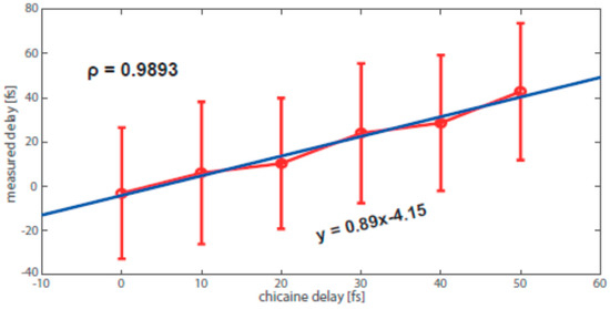
Figure 24.
Chicane delay vs. two-color pulse delay measured with the PALM, and their correlation ρ (reproduced with permission from [110], Copyright Optical Society, 2017).
The experiment presented in [109] also checked the streaking effect at several photon energies ranging from 5 keV to 9 keV. The goal was to observe the streaking shift, and the accompanying streaking slope, get stronger or weaker depending on the X-ray photon energy. The experiment showed the expected relationship between the accuracy of the arrival time measurement and the kinetic energy of the electrons ionized by the FEL pulse, shown in Figure 25.
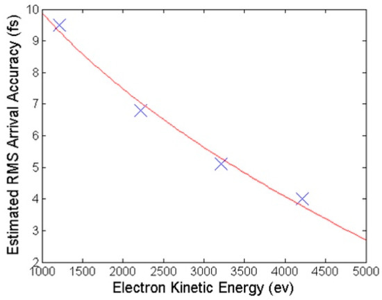
Figure 25.
Arrival time accuracy as a function of electron kinetic energy, as shown in [109] (reproduced with permission from [109], Copyright Optical Society, 2014). The blue crosses are the data points, while the red curve is the square root function that best fits them.
In conclusion, the experiments on THz streaking of hard X-ray pulses worked as expected and the signal strengths on a shot-to-shot basis, as reported in [109], were more than sufficient for single-shot temporal measurements. Based on these experiments, there seems to be no reason why the technique could not be extended to even higher photon energies, and ideas for adapting the device to handle larger jitters between the FEL laser and the experimental laser are also being considered [113].
4. Outlook
4.1 Angular Streaking—Full Time–Energy SASE Pulse Retrieval
All intensity dependent experiments at free-electron lasers are highly affected by the effective pulse durations and SASE caused sub-spikes in the XFEL pulses. Mostly, such experiments rely on pulse energy measurements by gas detectors or other methods averaging over the intensity distribution of the XFEL pulses. However, the physical processes under investigation often depend on the peak intensity, which is hidden in the unresolved spike structure of the pulses. In addition to the strong impact on the broad field of non-linear physics, developments towards mode-locking [114,115,116] and the generation of X-ray pulses on the attosecond timescale [34,35,36,37] are currently in progress and will ultimately originate the scientific field of attosecond X-ray physics. This imminent breakthrough demands unprecedented time resolution for the temporal characterization of the structure of SASE XFEL pulses under various modes of operation. Such possibilities desperately need a direct single-shot method to diagnose not merely the X-ray pulse duration, but also the full temporal coherence properties of the XFEL pulses including the spectral chirp of the X-rays and the stochastic sub-spikes of the SASE pulses.
Another essential requirement for every ultrafast experiment that relies on a synchronized optical laser for pump or probe is precise information about the relative arrival time between the two lasers. Steady progress in this regard has been made [51,52,58,69,101,103,117,118,119,120], as was demonstrated throughout this review, and electron acceleration designs relying on superconducting linear accelerators [19,20] open up even better prospects for temporal synchronization [121]. Nevertheless, a complete and direct single-shot measurement in the time domain that reports both the exact XFEL pulse temporal structure and arrival time simultaneously and which is applicable over a broad range of X-ray pulse durations remains elusive.
A possible solution to all these challenges could be the method of two-color angle-resolved circular streaking spectroscopy of photoelectrons or Auger electrons, dubbed ‘angular streaking’ in the following for brevity. The measurement builds on the above described experiences with linear X-ray photoelectron streaking spectroscopy [69,103]. The need for a measurement technique capable of coping with varying pulse shapes and arrival times with respect to the lab time frame on a shot-to-shot basis is recognized and taken into account in this setup by employing a streaking laser with circular polarization in combination with a ring-like arrangement of 16 high-efficiency time-of-flight spectrometers [122]. This scheme has recently also been theoretically described [123,124] and evaluated for application at realistic XFEL parameters by a quasiclassical description supported with numerical calculations based on a quantum-mechanical approach (see Figure 26).
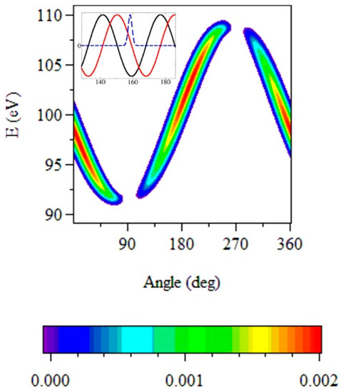
Figure 26.
Simulation of circular streaking. Color-scaled streaking spectra as a function of the emission angle of photoelectrons produced by an ultrashort X-ray pulse (FWHM of the field is 2.8 fs) assisted by the THz field of 1.7 × 10¹⁰ W cm−2 intensity, 300 fs duration and 28.2 THz frequency. The electron kinetic energy (without the THz field) is 100 eV. In the inset, the X-ray and THz pulses are shown in arbitrary units. Time (in fs) is counted from the onset of the THz pulse. The black and red lines are, respectively, the x- and y-component of the THz field. (reproduced with permission from [124], Copyright IOP Publishing, 2017).
The vector potential of the streaking field rotates in the lab frame with a well-specified period, like the hand of a clock, and imprints the XFEL pulse temporal structure onto the angularly resolved distribution of streaked photoelectrons [63,125,126]. Varying the wavelength of the circular streaking field allows to set the period of the ‘clock’ and thus the temporal resolution of the measurement. While capable of measuring the shortest X-ray FEL pulses with a resolution of ~160 attoseconds at 800 nm, the resolution can easily be adapted to longer pulse durations via the adjustable streaking wavelength. To avoid ambiguities, the period of the streaking laser field has to be larger than the XFEL pulse duration.
At the same time, the relative strength of the streaking effect gives information about the arrival time shift from shot to shot. Moreover, this setup allows to investigate the shift of the photoelectron energy versus delay within a single X-ray pulse and thus measure its instantaneous frequency. For the first time, this would provide the direct measurement of residual X-ray pulse chirp from the different electron bunch compression settings, pointing the way toward full XFEL spectral phase control and chirped pulse amplification.
The proposed extended and angle-resolving method of streaking can be realized with an array of 16 independently working time-of-flight spectrometers which are aligned in the dipole plane of the incoming light (see Figure 27, left). As described previously, the circularly polarized streaking laser and the XFEL have to be overlapped spatially and temporally in the experimental chamber, where the X-ray pulse ionizes a diluted noble gas e.g., xenon. In the presence of the optical field the original angular distribution of photoelectrons is redistributed according to the rotational angle of the vector potential at the moment of their generation. Thus, photoelectrons generated from different parts within the XFEL pulse envelope are streaked at different angles, effectively mapping time to angle (Figure 27, right). We therefore do not require precise knowledge of the X-ray arrival time on the scale of the carrier phase of the streaking laser, as was the case in past streaking experiments, where temporal overlap with the linear ramp of the linearly polarized vector potential enabled the photoelectron energy shift-to-time mapping. Since the information of the XFEL pulse structure is given through the relative change in angular distribution within each single XFEL shot, we expect this technique to be more robust with regards to pulse energy instabilities and less demanding with regards to the optical pulse shape.
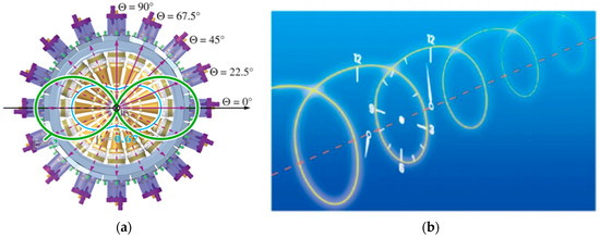
Figure 27.
Conceptual design of angular streaking. (a) Sketch of the experimental chamber with 16 independent time-of-flight spectrometers (reprinted under the terms of the Creative Commons Attribution 3.0 License from [122]). (b) The vector potential of the optical streaking laser rotates similar to the hand of a watch. Photoelectrons resulting from different parts of the X-ray pulse are therefore streaked at different angles, allowing the reconstruction of the X-ray temporal profile (reproduced with permission from [127], Copyright Nature Publishing Group, 2011).
First demonstration measurements with this setup have successfully been conducted at the Linac Coherent Light Source in California, USA, and the results are being analyzed at the moment by some of the authors of this article. The first impression of the data is very encouraging, giving rise to the expectation of an adjustable online characterization method for complete shot-to-shot arrival time and time–energy X-ray FEL pulse reconstruction in the near future.
4.2. Tandem Phase-Shifted Geometry for Infrared Streaking and Attosecond Resolution
As discussed, to further improve the resolution of the linear THz streaking measurements to the sub-femtosecond level, streaking pulses with a shorter rise time in the IR spectral region must be used. These pulses, however, consist of multiple electric field cycles and are typically not carrier–envelope phase stabilized. As a result, it not possible to control the streaking field amplitude and phase due to the temporal jitter at XFELs. Crucially, without defined streaking parameters it would not be possible to perform a calibrated transformation from energy to time.
This problem can be addressed by recording two streaked photoelectron spectra for each X-ray pulse, using a phase-shifted streaking pulse in a tandem streaking geometry as illustrated in Figure 28. As usual, the instantaneous vector potential A(t) is determined by analysing the shift in the centroid of the dressed photoemission. Qualitatively, due to the fact that the measurements are made with phase-shifted streaking fields, the value of the instantaneous vector potential of one measurement gives the gradient of the field in the other and vice versa, thus providing all of the information required to yield a calibrated measurement of the temporal profile of the photoemission and corresponding X-ray pulse. The instantaneous amplitude and phase of the streaking field can also be combined to determine the cycle-averaged amplitude of the IR streaking laser pulse, which gives the precise overlap between the X-ray pulse and envelope of the streaking laser pulse for use in pump/probe experiments.
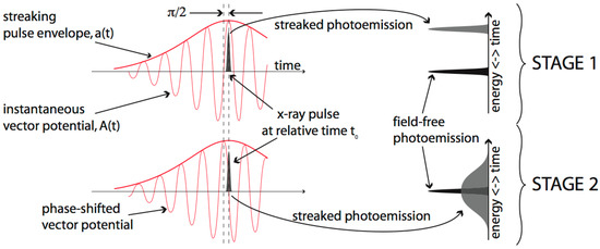
Figure 28.
Principle of self-calibrated streaking measurements made with multi-cycle infrared fields. In the first stage the X-ray pulse overlaps with a maximum of the vector potential, resulting in a maximal energy shift of the streaked photoelectron spectrum by an amount proportional to the instantaneous vector potential. In the second stage the photoemission occurs at a zero-crossing of the vector potential, resulting in a maximally broadened photoelectron spectrum. The magnitude of the shift in kinetic energy, observed in the first stage measurement, gives the gradient of the vector potential in the second stage measurement. Combined, this information enables a calibrated transformation of the second stage measurement from energy to time.
In practice, the Gouy phase shift can be used to introduce a controlled and fixed phase shift between the two different stages of the streaking measurement required for self-calibration. To achieve a phase shift, streaking measurements would be performed at one Rayleigh length upstream and downstream of the laser focus. A precise phase shift between the measurements allows for full temporal characterization of the X-ray pulse, but the technique is applicable for any phase shift as long as it is constant.
For a phase shift the instantaneous streaking fields in each stage of the streaking measurement for an arbitrary overlap t0 between streaking pulse (of arbitrary carrier–envelope offset φ0) and the X-ray pulse are:
and
As usual, A1(t0) and A2(t0) would be found by inverting the expression for the energy shift in the streaked photoemission, which is to first order: , compare also Equation (1). Here, pc is the initial photoelectron momentum.
Conceptually, to transform broadened or streaked spectra from kinetic energy to time, the streaking strength or derivative of the instantaneous streaking field must also be known. From the expressions for the arbitrary streaking field at the phase-shifted streaking measurements, it is clear that the instantaneous vector potential in the second measurement is proportional to the derivative of the instantaneous vector potential in the first and vice versa, where the proportionality constant is ωL the carrier frequency of the IR streaking field.
Using this crucial information, each streaked spectrum provides an independent measurement of the X-ray pulse profile. Furthermore, if the phase relationship between the streaking fields in the two measurements is , the value of the cycle-averaged amplitude at the point of overlap is simply . Then, if the laser pulse envelope is well characterized, this can be inverted to provide the precise time of arrival of the X-ray pulse and the temporal characterization is complete.
Beyond pulse characterization, the streaking technique may also be used to study few-femtosecond electron dynamics at XFELs. For example, the interaction of matter with high-fluence X-ray pulses of durations of few femtoseconds triggers complex dynamics in the electronic system that are not yet fully understood. Photoelectron streaking spectroscopy provides the possibility to study these dynamics on a femtosecond time scale. As a first approach, Auger decay lifetime of simple gas-phase molecules could be measured directly in the temporal domain. Synchrotron sources have been used to measure the lifetime of core holes from the spectral width of the electrons emitted during the decay of the excited state. However, these measurements fail to provide details of the temporal evolution of the excited state, when multi-electron dynamics are involved. In contrast, at XFELs with photoelectron streaking spectroscopy, the temporal evolution of highly excited states and corresponding relaxation dynamics can also be investigated.
Acknowledgments
W.H. acknowledges financial support from a Marie Curie International Outgoing Fellowship. W.H. and R.K. acknowledge financial support by the BaCaTeC program. T.M., M.I. and M.M. acknowledge support by the Deutsche Forschungsgemeinschaft (DFG) under grant nos. SFB925/A1 and SFB 925/A3. M.I. acknowledges funding from the VW foundation within a Peter Paul Ewald-Fellowship. A.R.M. acknowledges funding through BMBF 05K16GU2. J.T.C. acknowledges support from Science Foundation Ireland under grant nos. 12/IA/1742 and 16/RI/3696. Part of this research was carried out at the Linac Coherent Light Source (LCLS) at the SLAC National Accelerator Laboratory. LCLS is an Office of Science User Facility operated for the U.S. Department of Energy (DOE) Office of Science by Stanford University.
Author Contributions
All authors contributed equally to the publication.
Conflicts of Interest
The authors declare no conflict of interest.
References
- Roentgen, W.C. Ueber eine neue Art von Strahlen. Sitzungsberichte der Würzburger Phys.-medic. Ges. 1895, 132. [Google Scholar]
- Elder, F.R.; Gurewitsch, A.M.; Langmuir, R.V.; Pollock, H.C. Radiation from Electrons in a Synchrotron. Phys. Rev. 1947, 71, 829–830. [Google Scholar] [CrossRef]
- Madden, R.P.; Codling, K. New Autoionizing Atomic Energy Levels in He, Ne, and Ar. Phys. Rev. Lett. 1963, 10, 516–518. [Google Scholar] [CrossRef]
- Rowe, E.M.; Mills, F.E. TANTALUS I: A Dedicated Storage Ring Synchrotron Radiation Source. Part. Accel. 1973, 4, 211–227. [Google Scholar]
- Halbach, K. Design of permanent multipole magnets with oriented rare earth cobalt material. Nucl. Instrum. Methods 1980, 169, 1–10. [Google Scholar] [CrossRef]
- Christov, I.P.; Murnane, M.M.; Kapteyn, H.C. High-Harmonic Generation of Attosecond Pulses in the “Single-Cycle” Regime. Phys. Rev. Lett. 1997, 78, 1251–1254. [Google Scholar] [CrossRef]
- Deacon, D.; Elias, L.; Madey, J.; Ramian, G.; Schwettman, H.; Smith, T. First Operation of a Free-Electron Laser. Phys. Rev. Lett. 1977, 38, 892–894. [Google Scholar] [CrossRef]
- McNeil, B.W.J.; Thompson, N.R. X-ray free-electron lasers. Nat. Photonics 2010, 4, 814–821. [Google Scholar] [CrossRef]
- Ackermann, W.; Asova, G.; Ayvazyan, V.; Azima, A.; Baboi, N.; Bähr, J.; Balandin, V.; Beutner, B.; Brandt, A.; Bolzmann, A.; et al. Operation of a free-electron laser from the extreme ultraviolet to the water window. Nat. Photonics 2007, 1, 336–342. [Google Scholar] [CrossRef]
- Allaria, E.; Appio, R.; Badano, L.; Barletta, W.A.; Bassanese, S.; Biedron, S.G.; Borga, A.; Busetto, E.; Castronovo, D.; Cinquegrana, P.; et al. Highly coherent and stable pulses from the FERMI seeded free-electron laser in the extreme ultraviolet. Nat. Photonics 2012, 6, 699–704. [Google Scholar] [CrossRef]
- Emma, P.; Akre, R.; Arthur, J.; Bionta, R.; Bostedt, C.; Bozek, J.D.; Brachmann, A.; Bucksbaum, P.H.; Coffee, R.N.; Decker, F.-J.; et al. First lasing and operation of an ångstrom-wavelength free-electron laser. Nat. Photonics 2010, 4, 641–647. [Google Scholar] [CrossRef]
- Ishikawa, T.; Aoyagi, H.; Asaka, T.; Asano, Y.; Azumi, N.; Bizen, T.; Ego, H.; Fukami, K.; Fukui, T.; Furukawa, Y.; et al. A compact X-ray free-electron laser emitting in the sub-ångström region. Nat. Photonics 2012, 6, 540–544. [Google Scholar] [CrossRef]
- Ganter, R. PSI—SwissFEL Conceptual Design Report. 5232 Villigen PSI, Switzerland. 2012. Available online: https://www.psi.ch/swissfel/CurrentSwissFELPublicationsEN/SwissFEL_CDR_V20_23.04.12_small.pdf (accessed on 1 September 2017).
- Kang, H.-S.; Han, J.H.; Kim, C.; Kim, D.E.; Kim, S.H.; Park, K.-H.; Park, S.-J.; Kang, T.-H.; Ko, I.S. Current status of PAL-XFEL project. In Proceedings of the IPAC2013, Shanghai, China, 12–17 May 2013; pp. 2074–2076. Available online: https://accelconf.web.cern.ch/accelconf/IPAC2013/papers/weodb103.pdf (accessed on 1 September 2017).
- Nakajima, K. Compact X-ray sources: Towards a table-top free-electron laser. Nat. Phys. 2008, 4, 92–93. [Google Scholar] [CrossRef]
- Maier, A.R.; Meseck, A.; Reiche, S.; Schroeder, C.B.; Seggebrock, T.; Grüner, F. Demonstration Scheme for a Laser-Plasma-Driven Free-Electron Laser. Phys. Rev. X 2012, 2, 31019. [Google Scholar] [CrossRef]
- Maier, A.R.; Kirchen, M.; Grüner, F. Brilliant Light Sources driven by Laser-Plasma Accelerators. In Synchrotron Light Sources and Free-Electron Lasers; Springer International Publishing: Cham, Switzerland, 2016; pp. 1–22. [Google Scholar]
- Kärtner, F.X.; Ahr, F.; Calendron, A.-L.; Çankaya, H.; Carbajo, S.; Chang, G.; Cirmi, G.; Dörner, K.; Dorda, U.; Fallahi, A.; et al. AXSIS: Exploring the frontiers in attosecond X-ray science, imaging and spectroscopy. Nucl. Instrum. Methods Phys. Res. Sect. A Accel. Spectrom. Detect. Assoc. Equip. 2016, 829, 24–29. [Google Scholar] [CrossRef] [PubMed]
- Altarelli, M.; Brinkmann, R.; Chergui, M.; Decking, W.; Dobson, B.; Düsterer, S.; Grübel, G.; Graeff, W.; Graafsma, H.; Hajdu, J.; et al. The European X-ray Free-Electron Laser—Technical Design Report; Notkestrasse: Hamburg, Germany, 2007; Available online: http://xfel.desy.de/localfsExplorer_read?currentPath=/afs/desy.de/group/xfel/wof/EPT/TDR/XFEL-TDR-final.pdf (accessed on 1 September 2017).
- Galayda, J. The new LCLS-II project: Status and challenges. In Proceedings of the LINAC2014, Geneva, Switzerland, 31 August–5 September 2014; Available online: https://inspirehep.net/record/1363411 (accessed on 1 September 2017).
- Drescher, M.; Hentschel, M.; Kienberger, R.; Uiberacker, M.; Yakovlev, V.S.; Scrinzi, A.; Westerwalbesloh, T.; Kleineberg, U.; Heinzmann, U.; Krausz, F. Time-resolved atomic inner-shell spectroscopy. Nature 2002, 419, 803–807. [Google Scholar] [CrossRef] [PubMed]
- Uiberacker, M.; Uphues, T.; Schultze, M.; Verhoef, A.J.; Yakovlev, V.S.; Kling, M.F.; Rauschenberger, J.; Kabachnik, N.M.; Schröder, H.; Lezius, M.; et al. Attosecond real-time observation of electron tunnelling in atoms. Nature 2007, 446, 627–632. [Google Scholar] [CrossRef] [PubMed]
- Cavalieri, A.L.; Müller, N.; Uphues, T.; Yakovlev, V.S.; Baltuška, A.; Horvath, B.; Schmidt, B.; Blümel, L.; Holzwarth, R.; Hendel, S.; et al. Attosecond spectroscopy in condensed matter. Nature 2007, 449, 1029–1032. [Google Scholar] [CrossRef] [PubMed]
- Schultze, M.; Fieß, M.; Karpowicz, N.; Gagnon, J.; Korbman, M.; Hofstetter, M.; Neppl, S.; Cavalieri, A.L.; Komninos, Y.; Mercouris, T.; et al. Delay in photoemission. Science 2010, 328, 1658–1662. [Google Scholar] [CrossRef] [PubMed]
- Klünder, K.; Dahlström, J.; Gisselbrecht, M.; Fordell, T.; Swoboda, M.; Guénot, D.; Johnsson, P.; Caillat, J.; Mauritsson, J.; Maquet, A.; et al. Probing Single-Photon Ionization on the Attosecond Time Scale. Phys. Rev. Lett. 2011, 106. [Google Scholar] [CrossRef] [PubMed]
- Schultze, M.; Ramasesha, K.; Pemmaraju, C.D.; Sato, S.A.; Whitmore, D.; Gandman, A.; Prell, J.S.; Borja, L.J.; Prendergast, D.; Yabana, K.; et al. Attosecond band-gap dynamics in silicon. Science 2014, 346, 1348–1352. [Google Scholar] [CrossRef] [PubMed]
- Neppl, S.; Ernstorfer, R.; Cavalieri, A.L.; Lemell, C.; Wachter, G.; Magerl, E.; Bothschafter, E.M.; Jobst, M.; Hofstetter, M.; Kleineberg, U.; et al. Direct observation of electron propagation and dielectric screening on the atomic length scale. Nature 2015, 517, 342–346. [Google Scholar] [CrossRef] [PubMed]
- Sabbar, M.; Heuser, S.; Boge, R.; Lucchini, M.; Carette, T.; Lindroth, E.; Gallmann, L.; Cirelli, C.; Keller, U. Resonance Effects in Photoemission Time Delays. Phys. Rev. Lett. 2015, 115, 133001. [Google Scholar] [CrossRef] [PubMed]
- Kraus, P.M.; Mignolet, B.; Baykusheva, D.; Rupenyan, A.; Horny, L.; Penka, E.F.; Grassi, G.; Tolstikhin, O.I.; Schneider, J.; Jensen, F.; et al. Measurement and laser control of attosecond charge migration in ionized iodoacetylene. Science 2015, 350, 790–795. [Google Scholar] [CrossRef] [PubMed]
- Förg, B.; Schötz, J.; Süßmann, F.; Förster, M.; Krüger, M.; Ahn, B.; Okell, W.A.; Wintersperger, K.; Zherebtsov, S.; Guggenmos, A.; et al. Attosecond nanoscale near-field sampling. Nat. Commun. 2016, 7, 11717. [Google Scholar] [CrossRef] [PubMed]
- Ossiander, M.; Siegrist, F.; Shirvanyan, V.; Pazourek, R.; Sommer, A.; Latka, T.; Guggenmos, A.; Nagele, S.; Feist, J.; Burgdörfer, J.; et al. Attosecond correlation dynamics. Nat. Phys. 2016, 1. [Google Scholar] [CrossRef]
- Emma, P.; Bane, K.; Cornacchia, M.; Huang, Z.; Schlarb, H.; Stupakov, G.; Walz, D. Femtosecond and Subfemtosecond X-ray Pulses from a Self-Amplified Spontaneous-Emission–Based Free-Electron Laser. Phys. Rev. Lett. 2004, 92, 74801. [Google Scholar] [CrossRef] [PubMed]
- Ding, Y.; Behrens, C.; Coffee, R.; Decker, F.-J.; Emma, P.; Field, C.; Helml, W.; Huang, Z.; Krejcik, P.; Krzywinski, J.; et al. Generating femtosecond X-ray pulses using an emittance-spoiling foil in free-electron lasers. Appl. Phys. Lett. 2015, 107, 191104. [Google Scholar] [CrossRef]
- Zholents, A.; Fawley, W. Proposal for Intense Attosecond Radiation from an X-ray Free-Electron Laser. Phys. Rev. Lett. 2004, 92, 224801. [Google Scholar] [CrossRef] [PubMed]
- Saldin, E.L.; Schneidmiller, E.A.; Yurkov, M.V. A new technique to generate 100 GW-level attosecond X-ray pulses from the X-ray SASE FELs. Opt. Commun. 2004, 239, 161–172. [Google Scholar] [CrossRef]
- Prat, E.; Reiche, S. Simple Method to Generate Terawatt-Attosecond X-ray Free-Electron-Laser Pulses. Phys. Rev. Lett. 2015, 114, 244801. [Google Scholar] [CrossRef] [PubMed]
- Kumar, S.; Parc, Y.W.; Landsman, A.S.; Kim, D.E. Temporally-coherent terawatt attosecond XFEL synchronized with a few cycle laser. Sci. Rep. 2016, 6, 37700. [Google Scholar] [CrossRef] [PubMed]
- Zholents, A.A.; Penn, G. Obtaining attosecond X-ray pulses using a self-amplified spontaneous emission free electron laser. Phys. Rev. Spec. Top. Accel. Beams 2005, 8, 50704. [Google Scholar] [CrossRef]
- Picón, A.; Lehmann, C.S.; Bostedt, C.; Rudenko, A.; Marinelli, A.; Osipov, T.; Rolles, D.; Berrah, N.; Bomme, C.; Bucher, M.; et al. Hetero-site-specific X-ray pump-probe spectroscopy for femtosecond intramolecular dynamics. Nat. Commun. 2016, 7, 11652. [Google Scholar] [CrossRef] [PubMed]
- Pande, K.; Hutchison, C.D.M.; Groenhof, G.; Aquila, A.; Robinson, J.S.; Tenboer, J.; Basu, S.; Boutet, S.; DePonte, D.P.; Liang, M.; et al. Femtosecond structural dynamics drives the trans/cis isomerization in photoactive yellow protein. Science 2016, 352, 725–729. [Google Scholar] [CrossRef] [PubMed]
- Yakovlev, V.S.; Stockman, M.I.; Krausz, F.; Baum, P. Atomic-scale diffractive imaging of sub-cycle electron dynamics in condensed matter. Sci. Rep. 2015, 5, 14581. [Google Scholar] [CrossRef] [PubMed]
- Yang, J.; Guehr, M.; Vecchione, T.; Robinson, M.S.; Li, R.; Hartmann, N.; Shen, X.; Coffee, R.; Corbett, J.; Fry, A.; et al. Diffractive imaging of a rotational wavepacket in nitrogen molecules with femtosecond megaelectronvolt electron pulses. Nat. Commun. 2016, 7, 11232. [Google Scholar] [CrossRef] [PubMed]
- Yang, J.; Guehr, M.; Shen, X.; Li, R.; Vecchione, T.; Coffee, R.; Corbett, J.; Fry, A.; Hartmann, N.; Hast, C.; et al. Diffractive Imaging of Coherent Nuclear Motion in Isolated Molecules. Phys. Rev. Lett. 2016, 117, 153002. [Google Scholar] [CrossRef] [PubMed]
- Glownia, J.M.; Natan, A.; Cryan, J.P.; Hartsock, R.; Kozina, M.; Minitti, M.P.; Nelson, S.; Robinson, J.; Sato, T.; van Driel, T.; et al. Self-Referenced Coherent Diffraction X-ray Movie of Ångstrom- and Femtosecond-Scale Atomic Motion. Phys. Rev. Lett. 2016, 117, 153003. [Google Scholar] [CrossRef] [PubMed]
- Bostedt, C.; Fritz, D.M.; Huang, Z.; Lee, H.J.; Lemke, H.; Schlotter, W.F.; Turner, J.J.; Williams, G.J. Linac Coherent Light Source: The First Five Years. Rev. Mod. Phys. 2015, 88. [Google Scholar] [CrossRef]
- Milton, S.V.; Gluskin, E.; Arnold, N.D.; Benson, C.; Berg, W.; Biedron, S.G.; Borland, M.; Chae, Y.C.; Dejus, R.J.; Den Hartog, P.K.; et al. Exponential gain and saturation of a self-amplified spontaneous emission free-electron laser. Science 2001, 292, 2037–2041. [Google Scholar] [CrossRef] [PubMed]
- Düsterer, S.; Rehders, M.; Al-Shemmary, A.; Behrens, C.; Brenner, G.; Brovko, O.; DellAngela, M.; Drescher, M.; Faatz, B.; Feldhaus, J.; et al. Development of experimental techniques for the characterization of ultrashort photon pulses of extreme ultraviolet free-electron lasers. Phys. Rev. Spec. Top. Accel. Beams 2014, 17, 120702. [Google Scholar] [CrossRef]
- Ding, Y.; Brachmann, A.; Decker, F.-J.; Dowell, D.; Emma, P.; Frisch, J.; Gilevich, S.; Hays, G.; Hering, P.; Huang, Z.; et al. Measurements and Simulations of Ultralow Emittance and Ultrashort Electron Beams in the Linac Coherent Light Source. Phys. Rev. Lett. 2009, 102, 254801. [Google Scholar] [CrossRef] [PubMed]
- Lutman, A.; Ding, Y.; Feng, Y.; Huang, Z.; Messerschmidt, M.; Wu, J.; Krzywinski, J. Femtosecond X-ray free electron laser pulse duration measurement from spectral correlation function. Phys. Rev. Spec. Top. Accel. Beams 2012, 15, 1–13. [Google Scholar] [CrossRef]
- Young, L.; Kanter, E.P.; Krässig, B.; Li, Y.; March, A.M.; Pratt, S.T.; Santra, R.; Southworth, S.H.; Rohringer, N.; Dimauro, L.F.; et al. Femtosecond electronic response of atoms to ultra-intense X-rays. Nature 2010, 466, 56–61. [Google Scholar] [CrossRef] [PubMed]
- Düsterer, S.; Radcliffe, P.; Bostedt, C.; Bozek, J.D.; Cavalieri, A.L.; Coffee, R.N.; Costello, J.T.; Cubaynes, D.; DiMauro, L.F.; Ding, Y.; et al. Femtosecond X-ray pulse length characterization at the Linac Coherent Light Source free-electron laser. New J. Phys. 2011, 13, 93024. [Google Scholar] [CrossRef]
- Behrens, C.; Decker, F.-J.; Ding, Y.; Dolgashev, V.A.; Frisch, J.; Huang, Z.; Krejcik, P.; Loos, H.; Lutman, A.; Maxwell, T.J.; et al. Few-femtosecond time-resolved measurements of X-ray free-electron lasers. Nat. Commun. 2014, 5, 3762. [Google Scholar] [CrossRef] [PubMed]
- Sanchez-Gonzalez, A.; Micaelli, P.; Olivier, C.; Barillot, T.R.; Ilchen, M.; Lutman, A.A.; Marinelli, A.; Maxwell, T.; Achner, A.; Agåker, M.; et al. Accurate prediction of X-ray pulse properties from a free-electron laser using machine learning. Nat. Commun. 2017, 8, 15461. [Google Scholar] [CrossRef] [PubMed]
- Mitzner, R.; Sorokin, A.A.; Siemer, B.; Roling, S.; Rutkowski, M.; Zacharias, H.; Neeb, M.; Noll, T.; Siewert, F.; Eberhardt, W.; et al. Direct autocorrelation of soft-X-ray free-electron-laser pulses by time-resolved two-photon double ionization of He. Phys. Rev. A 2009, 80, 25402. [Google Scholar] [CrossRef]
- Moshammer, R.; Pfeifer, T.; Rudenko, A.; Jiang, Y.H.; Foucar, L.; Kurka, M.; Kühnel, K.U.; Schröter, C.D.; Ullrich, J.; Herrwerth, O.; et al. Second-order autocorrelation of XUV FEL pulses via time resolved two-photon single ionization of He. Opt. Express 2011, 19, 21698. [Google Scholar] [CrossRef] [PubMed]
- Iaconis, C.; Walmsley, I.A. Spectral phase interferometry for direct electric-field reconstruction of ultrashort optical pulses. Opt. Lett. 1998, 23, 792–794. [Google Scholar] [CrossRef] [PubMed]
- Mahieu, B.; Gauthier, D.; De Ninno, G.; Dacasa, H.; Lozano, M.; Rousseau, J.-P.; Zeitoun, P.; Garzella, D.; Merdji, H. Spectral-phase interferometry for direct electric-field reconstruction applied to seeded extreme-ultraviolet free-electron lasers. Opt. Express 2015, 23, 17665–17674. [Google Scholar] [CrossRef] [PubMed]
- Harmand, M.; Coffee, R.; Bionta, M.R.; Chollet, M.; French, D.; Zhu, D.; Fritz, D.M.; Lemke, H.T.; Medvedev, N.; Ziaja, B.; et al. Achieving few-femtosecond time-sorting at hard X-ray free-electron lasers. Nat. Photonics 2013, 7, 215–218. [Google Scholar] [CrossRef]
- Finetti, P.; Höppner, H.; Allaria, E.; Callegari, C.; Capotondi, F.; Cinquegrana, P.; Coreno, M.; Cucini, R.; Danailov, M.B.; Demidovich, A.; et al. Pulse Duration of Seeded Free-Electron Lasers. Phys. Rev. X 2017, 7, 21043. [Google Scholar] [CrossRef]
- Bencivenga, F.; Cucini, R.; Capotondi, F.; Battistoni, A.; Mincigrucci, R.; Giangrisostomi, E.; Gessini, A.; Manfredda, M.; Nikolov, I.P.; Pedersoli, E.; et al. Four-wave mixing experiments with extreme ultraviolet transient gratings. Nature 2015, 520, 205–208. [Google Scholar] [CrossRef] [PubMed]
- Bencivenga, F.; Masciovecchio, C. Results and Perspectives for Short-Wavelength, Four-Wave-Mixing Experiments with Fully Coherent Free Electron Lasers. Synchrotron Radiat. News 2016, 29, 15–20. [Google Scholar] [CrossRef]
- Mairesse, Y.; Zeidler, D.; Dudovich, N.; Spanner, M.; Levesque, J.; Villeneuve, D.M.; Corkum, P.B. High-order harmonic transient grating spectroscopy in a molecular jet. Phys. Rev. Lett. 2008, 100, 15–18. [Google Scholar] [CrossRef] [PubMed]
- Itatani, J.; Quéré, F.; Yudin, G.; Ivanov, M.; Krausz, F.; Corkum, P. Attosecond Streak Camera. Phys. Rev. Lett. 2002, 88, 173903. [Google Scholar] [CrossRef] [PubMed]
- Kitzler, M.; Milosevic, N.; Scrinzi, A.; Krausz, F.; Brabec, T. Quantum Theory of Attosecond XUV Pulse Measurement by Laser Dressed Photoionization. Phys. Rev. Lett. 2002, 88, 173904. [Google Scholar] [CrossRef] [PubMed]
- Hentschel, M.; Kienberger, R.; Spielmann, C.; Reider, G.A.; Milosevic, N.; Brabec, T.; Corkum, P.B.; Heinzmann, U.; Drescher, M.; Krausz, F. Attosecond metrology. Nature 2001, 414, 509–513. [Google Scholar] [CrossRef] [PubMed]
- Kienberger, R.; Goulielmakis, E.; Uiberacker, M.; Baltuska, A.; Yakovlev, V.; Bammer, F.; Scrinzi, A.; Westerwalbesloh, T.; Kleineberg, U.; Heinzmann, U.; et al. Atomic transient recorder. Nature 2004, 427, 817–821. [Google Scholar] [CrossRef] [PubMed]
- Goulielmakis, E.; Uiberacker, M.; Kienberger, R.; Baltuška, A.; Yakovlev, V.S.; Scrinzi, A.; Westerwalbesloh, T.; Kleineberg, U.; Heinzmann, U.; Drescher, M.; et al. Direct measurement of light waves. Science 2004, 305, 1267–1269. [Google Scholar] [CrossRef] [PubMed]
- Baumgartner, R.; Byer, R. Optical parametric amplification. IEEE J. Quantum Electron. 1979, 15, 432–444. [Google Scholar] [CrossRef]
- Helml, W.; Maier, A.R.; Schweinberger, W.; Grguraš, I.; Radcliffe, P.; Doumy, G.; Roedig, C.; Gagnon, J.; Messerschmidt, M.; Schorb, S.; et al. Measuring the temporal structure of few-femtosecond free-electron laser X-ray pulses directly in the time domain. Nat. Photonics 2014, 8, 950–957. [Google Scholar] [CrossRef]
- Wuilleumier, F.J.; Meyer, M. Pump–probe experiments in atoms involving laser and synchrotron radiation: An overview. J. Phys. B At. Mol. Opt. Phys. 2006, 39, R425–R477. [Google Scholar] [CrossRef]
- Glover, T.; Schoenlein, R.; Chin, A.; Shank, C. Observation of Laser Assisted Photoelectric Effect and Femtosecond High Order Harmonic Radiation. Phys. Rev. Lett. 1996, 76, 2468–2471. [Google Scholar] [CrossRef] [PubMed]
- Meyer, M.; Costello, J.T.; Düsterer, S.; Li, W.B.; Radcliffe, P. Two-colour experiments in the gas phase. J. Phys. B At. Mol. Opt. Phys. 2010, 43, 194006. [Google Scholar] [CrossRef]
- Radcliffe, P.; Arbeiter, M.; Li, W.B.; Düsterer, S.; Redlin, H.; Hayden, P.; Hough, P.; Richardson, V.; Costello, J.T.; Fennel, T.; et al. Atomic photoionization in combined intense XUV free-electron and infrared laser fields. New J. Phys. 2012, 14, 43008. [Google Scholar] [CrossRef]
- O’Keeffe, P.; López-Martens, R.; Mauritsson, J.; Johansson, A.; L’Huillier, A.; Véniard, V.; Taïeb, R.; Maquet, A.; Meyer, M. Polarization effects in two-photon nonresonant ionization of argon with extreme-ultraviolet and infrared femtosecond pulses. Phys. Rev. A 2004, 69, 51401. [Google Scholar] [CrossRef]
- Radcliffe, P.; Düsterer, S.; Azima, A.; Redlin, H.; Feldhaus, J.; Dardis, J.; Kavanagh, K.; Luna, H.; Gutierrez, J.P.; Yeates, P.; et al. Single-shot characterization of independent femtosecond extreme ultraviolet free electron and infrared laser pulses. Appl. Phys. Lett. 2007, 90, 131108. [Google Scholar] [CrossRef]
- Redlin, H.; Al-Shemmary, A.; Azima, A.; Stojanovic, N.; Tavella, F.; Will, I.; Düsterer, S. The FLASH pump-probe laser system: Setup, characterization and optical beamlines. Nucl. Instrum. Methods Phys. Res. Sect. A Accel. Spectrom. Detect. Assoc. Equip. 2011, 635, S88–S93. [Google Scholar] [CrossRef]
- Schulz, S.; Grguraš, I.; Behrens, C.; Bromberger, H.; Costello, J.T.; Czwalinna, M.K.; Felber, M.; Hoffmann, M.C.; Ilchen, M.; Liu, H.Y.; et al. Femtosecond all-optical synchronization of an X-ray free-electron laser. Nat. Commun. 2015, 6, 5938. [Google Scholar] [CrossRef] [PubMed]
- Meyer, M.; Cubaynes, D.; O’Keeffe, P.; Luna, H.; Yeates, P.; Kennedy, E.T.; Costello, J.T.; Orr, P.; Taïeb, R.; Maquet, A.; et al. Two-color photoionization in xuv free-electron and visible laser fields. Phys. Rev. A 2006, 74, 11401. [Google Scholar] [CrossRef]
- Maquet, A.; Taïeb, R. Two-colour IR + XUV spectroscopies: the “soft-photon approximation”. J. Mod. Opt. 2007, 54, 1847–1857. [Google Scholar] [CrossRef]
- Meyer, M.; Cubaynes, D.; Glijer, D.; Dardis, J.; Hayden, P.; Hough, P.; Richardson, V.; Kennedy, E.T.; Costello, J.T.; Radcliffe, P.; et al. Polarization Control in Two-Color Above-Threshold Ionization of Atomic Helium. Phys. Rev. Lett. 2008, 101, 193002. [Google Scholar] [CrossRef] [PubMed]
- Hayden, P.; Dardis, J.; Hough, P.; Richardson, V.; Kennedy, E.T.; Costello, J.T.; Düsterer, S.; Redlin, H.; Feldhaus, J.; Li, W.B.; et al. The Laser-assisted photoelectric effect of He, Ne, Ar and Xe in intense extreme ultraviolet and infrared laser fields. J. Mod. Opt. 2016, 63, 358–366. [Google Scholar] [CrossRef]
- Azima, A.; Düsterer, S.; Radcliffe, P.; Redlin, H.; Stojanovic, N.; Li, W.; Schlarb, H.; Feldhaus, J.; Cubaynes, D.; Meyer, M.; et al. Time-resolved pump-probe experiments beyond the jitter limitations at FLASH. Appl. Phys. Lett. 2009, 94, 144102. [Google Scholar] [CrossRef]
- Ayvazyan, V.; Baboi, N.; Bähr, J.; Balandin, V.; Beutner, B.; Brandt, A.; Bohnet, I.; Bolzmann, A.; Brinkmann, R.; Brovko, O.I.; et al. First operation of a free-electron laser generating GW power radiation at 32 nm wavelength. Eur. Phys. J. D 2006, 37, 297–303. [Google Scholar] [CrossRef]
- Radcliffe, P.; Düsterer, S.; Azima, A.; Li, W.B.; Plönjes, E.; Redlin, H.; Feldhaus, J.; Nicolosi, P.; Poletto, L.; Dardis, J.; et al. An experiment for two-color photoionization using high intensity extreme-UV free electron and near-IR laser pulses. Nucl. Instrum. Methods Phys. Res. Sect. A Accel. Spectrom. Detect. Assoc. Equip. 2007, 583, 516–525. [Google Scholar] [CrossRef]
- Eland, J.H.D.; Vieuxmaire, O.; Kinugawa, T.; Lablanquie, P.; Hall, R.I.; Penent, F. Complete Two-Electron Spectra in Double Photoionization: The Rare Gases Ar, Kr, and Xe. Phys. Rev. Lett. 2003, 90, 53003. [Google Scholar] [CrossRef] [PubMed]
- Mazza, T.; Ilchen, M.; Rafipoor, A.J.; Callegari, C.; Finetti, P.; Plekan, O.; Prince, K.C.; Richter, R.; Demidovich, A.; Grazioli, C.; et al. Angular distribution and circular dichroism in the two-colour XUV + NIR above-threshold ionization of helium. J. Mod. Opt. 2016, 63, 367–382. [Google Scholar] [CrossRef]
- Gauthier, D.; Allaria, E.; Coreno, M.; Cudin, I.; Dacasa, H.; Danailov, M.B.; Demidovich, A.; Di Mitri, S.; Diviacco, B.; Ferrari, E.; et al. Chirped pulse amplification in an extreme-ultraviolet free-electron laser. Nat. Commun. 2016, 7, 13688. [Google Scholar] [CrossRef] [PubMed]
- Meyer, M.; Radcliffe, P.; Tschentscher, T.; Costello, J.T.; Cavalieri, A.L.; Grguras, I.; Maier, A.R.; Kienberger, R.; Bozek, J.; Bostedt, C.; et al. Angle-Resolved Electron Spectroscopy of Laser-Assisted Auger Decay Induced by a Few-Femtosecond X-ray Pulse. Phys. Rev. Lett. 2012, 108, 63007. [Google Scholar] [CrossRef] [PubMed]
- Mazza, T.; Ilchen, M.; Rafipoor, A.J.; Callegari, C.; Finetti, P.; Plekan, O.; Prince, K.C.; Richter, R.; Danailov, M.B.; Demidovich, A.; et al. Determining the polarization state of an extreme ultraviolet free-electron laser beam using atomic circular dichroism. Nat. Commun. 2014, 5, 3648. [Google Scholar] [CrossRef] [PubMed]
- Hartmann, G.; Lindahl, A.O.; Knie, A.; Hartmann, N.; Lutman, A.A.; MacArthur, J.P.; Shevchuk, I.; Buck, J.; Galler, A.; Glownia, J.M.; et al. Circular dichroism measurements at an x-ray free-electron laser with polarization control. Rev. Sci. Instrum. 2016, 87, 83113. [Google Scholar] [CrossRef] [PubMed]
- Düsterer, S.; Rading, L.; Johnsson, P.; Rouzée, A.; Hundertmark, A.; Vrakking, M.J.J.; Radcliffe, P.; Meyer, M.; Kazansky, A.K.; Kabachnik, N.M. Interference in the angular distribution of photoelectrons in superimposed XUV and optical laser fields. J. Phys. B At. Mol. Opt. Phys. 2013, 46, 164026. [Google Scholar] [CrossRef]
- Krausz, F.; Ivanov, M.Y. Attosecond physics. Rev. Mod. Phys. 2009, 81, 163–234. [Google Scholar] [CrossRef]
- Yakovlev, V.S.; Gagnon, J.; Karpowicz, N.; Krausz, F. Attosecond Streaking Enables the Measurement of Quantum Phase. Phys. Rev. Lett. 2010, 105, 3–6. [Google Scholar] [CrossRef] [PubMed]
- Gagnon, J.; Goulielmakis, E.; Yakovlev, V.S. The accurate FROG characterization of attosecond pulses from streaking measurements. Appl. Phys. B 2008, 92, 25–32. [Google Scholar] [CrossRef]
- Grguraš, I. Time Resolved Photoelectron Spectroscopy for Femtosecond Characterization of X-ray Free-Electron Laser Pulses. Ph.D. Thesis, Universität Hamburg, Hamburg, Germany, 2015. Available online: https://www.physnet.uni-amburg.de/services/biblio/dissertation/dissfbPhysik/___Kurzfassungen/Ivanka___Grguras (accessed on 1 September 2017).
- Helml, W. Development & Characterization of Sources for High-Energy, High-Intensity Coherent Radiation. Ph.D. Thesis, Technische Universität München, München, Germany, 2012. Available online: http://nbn-resolving.de/urn/resolver.pl?urn:nbn:de:bvb:91-diss-20120723–1110298–1-6 (accessed on 1 September 2017).
- Bozek, J.D. AMO instrumentation for the LCLS X-ray FEL. Eur. Phys. J. Spec. Top. 2009, 169, 129–132. [Google Scholar] [CrossRef]
- Kruit, P.; Read, F.H. Magnetic field paralleliser for 2π electron-spectrometer and electron-image magnifier. J. Phys. E 1983, 16, 313–324. [Google Scholar] [CrossRef]
- Gagnon, J.; Yakovlev, V.S. The robustness of attosecond streaking measurements. Opt. Express 2009, 17, 17678–17693. [Google Scholar] [CrossRef] [PubMed]
- Krinsky, S.; Gluckstern, R. Analysis of statistical correlations and intensity spiking in the self-amplified spontaneous-emission free-electron laser. Phys. Rev. Spec. Top. Accel. Beams 2003, 6, 50701. [Google Scholar] [CrossRef]
- Frühling, U.; Wieland, M.; Gensch, M.; Gebert, T.; Schütte, B.; Krikunova, M.; Kalms, R.; Budzyn, F.; Grimm, O.; Rossbach, J.; et al. Single-shot terahertz-field-driven X-ray streak camera. Nat. Photonics 2009, 3, 523–528. [Google Scholar] [CrossRef]
- Yeh, K.-L.; Hoffmann, M.C.; Hebling, J.; Nelson, K.A. Generation of 10 µJ ultrashort terahertz pulses by optical rectification. Appl. Phys. Lett. 2007, 90, 171121. [Google Scholar] [CrossRef]
- Grguraš, I.; Maier, A.R.; Behrens, C.; Mazza, T.; Kelly, T.J.; Radcliffe, P.; Düsterer, S.; Kazansky, A.K.; Kabachnik, N.M.; Tschentscher, T.; et al. Ultrafast X-ray pulse characterization at free-electron lasers. Nat. Photonics 2012, 6, 852–857. [Google Scholar] [CrossRef]
- Gagnon, J.; Yakovlev, V.S. The direct evaluation of attosecond chirp from a streaking measurement. Appl. Phys. B Lasers Opt. 2011, 103, 303–309. [Google Scholar] [CrossRef]
- Gouy, L.G. Sur Une Propriete Nouvelle Des Ondes Lumineuses. C. R. Acad. Sci. 1890, 110, 1251–1253. [Google Scholar]
- Wellhöfer, M.; Hoeft, J.T.; Martins, M.; Wurth, W.; Braune, M.; Viefhaus, J.; Tiedtke, K.; Richter, M. Photoelectron spectroscopy as a non-invasive method to monitor SASE-FEL spectra. J. Instrum. 2008, 3, P02003. [Google Scholar] [CrossRef]
- Bionta, M.R.; Lemke, H.T.; Cryan, J.P.; Glownia, J.M.; Bostedt, C.; Cammarata, M.; Castagna, J.-C.; Ding, Y.; Fritz, D.M.; Fry, A.R.; et al. Spectral encoding of X-ray/optical relative delay. Opt. Express 2011, 19, 21855–21865. [Google Scholar] [CrossRef] [PubMed]
- Henke, B.L.; Gullikson, E.M.; Davis, J.C. X-ray Interactions: Photoabsorption, Scattering, Transmission, and Reflection at E = 50–30,000 eV, Z = 1–92. At. Data Nucl. Data Tables 1993, 54, 181–342. [Google Scholar] [CrossRef]
- Juranić, P.N.; Stepanov, A.; Ischebeck, R.; Schlott, V.; Pradervand, C.; Patthey, L.; Radović, M.; Gorgisyan, I.; Rivkin, L.; Hauri, C.P.; et al. High-precision X-ray FEL pulse arrival time measurements at SACLA by a THz streak camera with Xe clusters. Opt. Express 2014, 22, 30004. [Google Scholar] [CrossRef] [PubMed]
- Gorgisyan, I.; Ischebeck, R.; Erny, C.; Dax, A.; Patthey, L.; Pradervand, C.; Sala, L.; Milne, C.; Lemke, H.T.; Hauri, C.P.; et al. THz streak camera method for synchronous arrival time measurement of two-color hard X-ray FEL pulses. Opt. Express 2017, 25, 2080. [Google Scholar] [CrossRef]
- Irimia, D.; Dobrikov, D.; Kortekaas, R.; Voet, H.; van den Ende, D.A.; Groen, W.A.; Janssen, M.H.M. A short pulse (7 µs FWHM) and high repetition rate (dc-5 kHz) cantilever piezovalve for pulsed atomic and molecular beams. Rev. Sci. Instrum. 2009, 80, 113303. [Google Scholar] [CrossRef] [PubMed]
- Hagena, O.F.; Obert, W. Cluster Formation in Expanding Supersonic Jets: Effect of Pressure, Temperature, Nozzle Size, and Test Gas. J. Chem. Phys. 1972, 56, 1793–1802. [Google Scholar] [CrossRef]
- Juranić, P.N.; Stepanov, A.; Peier, P.; Hauri, C.P.; Ischebeck, R.; Schlott, V.; Radović, M.; Erny, C.; Ardana-Lamas, F.; Monoszlai, B.; et al. A scheme for a shot-to-shot, femtosecond-resolved pulse length and arrival time measurement of free electron laser X-ray pulses that overcomes the time jitter problem between the FEL and the laser. J. Instrum. 2014, 9, P03006. [Google Scholar] [CrossRef]
- Thompson, N.R.; McNeil, B.W.J. Mode Locking in a Free-Electron Laser Amplifier. Phys. Rev. Lett. 2008, 100, 203901. [Google Scholar] [CrossRef] [PubMed]
- Kur, E.; Dunning, D.J.; McNeil, B.W.J.; Wurtele, J.; Zholents, A.A. A wide bandwidth free-electron laser with mode locking using current modulation. New J. Phys. 2011, 13, 63012. [Google Scholar] [CrossRef]
- Xiang, D.; Ding, Y.; Raubenheimer, T.; Wu, J. Mode-locked multichromatic x rays in a seeded free-electron laser for single-shot X-ray spectroscopy. Phys. Rev. Spec. Top. Accel. Beams 2012, 15, 50707. [Google Scholar] [CrossRef]
- Ding, Y.; Decker, F.-J.; Emma, P.; Feng, C.; Field, C.; Frisch, J.; Huang, Z.; Krzywinski, J.; Loos, H.; Welch, J.; et al. Femtosecond X-ray Pulse Characterization in Free-Electron Lasers Using a Cross-Correlation Technique. Phys. Rev. Lett. 2012, 109, 254802. [Google Scholar] [CrossRef] [PubMed]
- Riedel, R.; Al-Shemmary, A.; Gensch, M.; Golz, T.; Harmand, M.; Medvedev, N.; Prandolini, M.J.; Sokolowski-Tinten, K.; Toleikis, S.; Wegner, U.; et al. Single-shot pulse duration monitor for extreme ultraviolet and X-ray free-electron lasers. Nat. Commun. 2013, 4, 1731. [Google Scholar] [CrossRef] [PubMed]
- Maxwell, T.J.; Behrens, C.; Ding, Y.; Fisher, A.S.; Frisch, J.; Huang, Z.; Loos, H. Coherent-Radiation Spectroscopy of Few-Femtosecond Electron Bunches Using a Middle-Infrared Prism Spectrometer. Phys. Rev. Lett. 2013, 111, 184801. [Google Scholar] [CrossRef] [PubMed]
- Hartmann, N.; Helml, W.; Galler, A.; Bionta, M.R.; Grünert, J.; Molodtsov, S.L.; Ferguson, K.R.; Schorb, S.; Swiggers, M.L.; Carron, S.; et al. Sub-femtosecond precision measurement of relative X-ray arrival time for free-electron lasers. Nat. Photonics 2014, 8, 706–709. [Google Scholar] [CrossRef]
- Löhl, F.; Arsov, V.; Felber, M.; Hacker, K.; Jalmuzna, W.; Lorbeer, B.; Ludwig, F.; Matthiesen, K.-H.; Schlarb, H.; Schmidt, B.; et al. Electron Bunch Timing with Femtosecond Precision in a Superconducting Free-Electron Laser. Phys. Rev. Lett. 2010, 104, 144801. [Google Scholar] [CrossRef] [PubMed]
- Allaria, E.; Diviacco, B.; Callegari, C.; Finetti, P.; Mahieu, B.; Viefhaus, J.; Zangrando, M.; De Ninno, G.; Lambert, G.; Ferrari, E.; et al. Control of the Polarization of a Vacuum-Ultraviolet, High-Gain, Free-Electron Laser. Phys. Rev. X 2014, 4, 41040. [Google Scholar] [CrossRef]
- Kazansky, A.K.; Bozhevolnov, A.V.; Sazhina, I.P.; Kabachnik, N.M. Interference effects in angular streaking with a rotating terahertz field. Phys. Rev. A 2016, 93, 13407. [Google Scholar] [CrossRef]
- Kazansky, A.K.; Sazhina, I.P.; Nosik, V.L.; Kabachnik, N.M. Angular streaking and sideband formation in rotating terahertz and far-infrared fields. J. Phys. B At. Mol. Opt. Phys. 2017, 50, 105601. [Google Scholar] [CrossRef]
- Constant, E.; Taranukhin, V.; Stolow, A.; Corkum, P. Methods for the measurement of the duration of high-harmonic pulses. Phys. Rev. A 1997, 56, 3870–3878. [Google Scholar] [CrossRef]
- Eckle, P.; Smolarski, M.; Schlup, P.; Biegert, J.; Staudte, A.; Schöffler, M.; Muller, H.G.; Dörner, R.; Keller, U. Attosecond angular streaking. Nat. Phys. 2008, 4, 565–570. [Google Scholar] [CrossRef]
- Ueda, K.; Ishikawa, K.L. Attosecond science: Attoclocks play devil’s advocate. Nat. Phys. 2011, 7, 371–372. [Google Scholar] [CrossRef]
© 2017 by the authors. Licensee MDPI, Basel, Switzerland. This article is an open access article distributed under the terms and conditions of the Creative Commons Attribution (CC BY) license (http://creativecommons.org/licenses/by/4.0/).